
|
|
The Early FROG Engines - The “Bicycle-Spoke” Series
The present article replaces my far earlier effort on the same subject which was published in March 2008 on the late Ron Chernich’s now-frozen "Model Engine News" (MEN) website. Since then, a great deal of additional information has come to light, along with a number of significant corrections to our previous understandings regarding these motors. The fact that the MEN website is now frozen makes it impossible to update the articles posted there. Accordingly, I've judged it to be necessary to publish a comprehensively updated article on this web-site. The original article may still be accessed here on MEN, although I must warn readers that it contains some incorrect or incomplete information. Much of the material for the following article was derived from my own long experience with these engines as well as a study of contemporary advertisements and media commentary. However, a considerable amount I’m extremely grateful to my late and much missed mate David Owen, who was (as ever) unfailingly supportive of my efforts to get a handle on serial numbers for these engines, also encouraging me every step of the way. The late Bert Streigler was similarly helpful in providing serial numbers and images of examples in his own collection. Les Stone kindly provided a number of the images which appear with this article. Finally, my valued friend and colleague Kevin Richards was there for me as always with numerous helpful comments and suggestions. Kevin also supplied me with a number of key components to help me to restore several incomplete examples of these motors. Thanks, mates - I couldn't keep this up without you! I'd also like to express my very sincere appreciation of the contribution made by Mike Noakes of Cornwall, England. Mike did a great deal of work in piecing together the story of George Court, designer of the earliest FROG engines with which we are concerned here. I believe that this is the first article to present Court's full story, for which all the credit is due to Mike. I must acknowledge the much-appreciated assistance of reader Anthony Williams, who was kind enough to contant me following the original appearance of this article on MEN to make me aware of an unusual variant of the FROG 175 spark-ignition model which had escaped my attention. Several images supplied by Anthony appear with this revised article. Finally, I'd like to thank my valued Aussie mate Gordon Beeby, who dug deep into his collection of early "Aeromodeller" magazines to uncover a few highly relevant pieces of documentary evidence. Without such support from my readers, I would have little right to claim any level of authority for my articles. Having acknowledged my sources, let’s begin by examining the background to the introduction of these interesting little engines. Background
In 1932, in order to enhance their marketing capabilities, the trio entered into partnership with the prominent Lines Brothers organization, whose marketing reach extended not only throughout Britain but also to many other parts of the world. Lines Brothers had been major players in the British toy industry since 1919, building upon a family involvement in that industry which had begun in around 1850.
Following the merger with Lines Brothers, the IMA production facilities were co-located with the main Triang toy manufacturing works at Morden Road. However, Mansour and the Wilmots continued to direct the activities of IMA. At this stage, IMA was operated more as a partner than as a subsidiary. The “FROG” trade name and associated trade-mark had been used from the outset by IMA, even before their tie-in with Lines Brothers. Their original focus was on the manufacture of ready-to-fly model aircraft and flying model kits - FROG model engine production was strictly a post-war development. IMA are notable for having been the first company in the world to introduce non-flying molded plastic model aircraft kits, which they did in 1936 with their “Penguin” range. The name arises from the fact that a penguin is a bird that doesn’t fly…………….. As might be expected, Lines Brothers suspended toy manufacture during the war years, turning all their facilities over to war production. No fewer than 7,000 people were employed at the Merton factory during this period, eventually making over 1,000,000 Sten guns and 14,000,000 magazines for Hurricane and Spitfire aircraft as well as shell cases, land mine cases and special optical apparatus to help troops see in the dark. The facilities of their IMA partner were applied to the production of both flying models for target purposes and 1:72 scale static models for aircraft identification training. In 1940 the factory was partially destroyed by enemy bombing, but repairs were immediately put in hand to restore full production, which was maintained throughout the war years.
The departure of Wilmot and Mansour was widely viewed as a matter for regret by those who remained behind at IMA. Following this unhappy development, Lines Brothers assumed outright control of IMA, operating it thereafter as a wholly-owned subsidiary from their Morden Road location. Thankfully, they had the wisdom to install a management and technical team who were very well versed in the intricacies of the model trade. Following the conclusion of hostilities in mid 1945, the company quickly resumed its former activities, including the manufacture of model aircraft products by its IMA subsidiary. Thanks in large part to its association with Lines Brothers, IMA entered the post-war period as one of the world's major manufacturers of model aircraft and related products. Accordingly, it wasn’t long before the rising post-war profile of power modelling led to the manufacture of model engines being added to the other product lines marketed under the FROG banner. The first FROG model engine, the FROG 175 spark ignition motor, appeared in early 1946. More of that model in its place below .....
Throughout their sixteen-year existence as a model engine manufacturer, IMA remained notable for their interesting and often innovative engine designs, frequently straying from the well-trodden design pathways. Their “bicycle spoke” series which forms the main subject of the present article was well out of the contemporary rut in design terms, as we shall soon see. They were early in the glow-plug ignition field in Britain with their 160 Red Glow model of 1948 (see below), going on to produce perhaps the best general-purpose British glow-plug motor of the early to mid 1950’s, the sturdy and dependable FROG 500 Red Glow, which reversed the usual trend by making a later retroactive appearance as a spark-ignition model. In the mid 1950’s they introduced the diaphragm-induction FROG 149 Vibramatic, an innovative one-of-a-kind design which worked surprisingly well. That model too appeared in a glow-plug version in addition to its more common diesel form. Finally, their later use of drum-valve induction in both their FROG 349 and FROG Viper 149 models was highly individualistic in a British context, as was the use of cross-flow loop scavenging in the FROG 349. Let’s now begin our survey of the early FROG model engines by returning to 1946 and the beginning of IMA’s involvement with model engine production. Early 1946 - The FROG 175 Makes Its Debut
The impending appearance of the FROG 175 was announced by IMA in their display at the Model Aircraft Exhibition of December 1945 held at Dorland Hall in London. Prototypes of the engine were on display, while full production was said to be only a few months away. The IMA exhibit was described in an article by D. J. Laidlaw-Dickson which appeared in the March 1946 issue of "Aeromodeller" magazine. The writer mentioned having seen prototypes in action in the field, stating that he could "vouch for their excellence".
It’s important for context to remember that as of early 1946 the spark ignition engine remained very much the accepted standard for power modelling in Britain. Although the development of model diesels was well advanced on the Continent and in Scandinavia by this time, that type of powerplant was still in its early development The advent of the miniature model glow plug in commercial form still lay almost two years in the future as of early 1946. The spark ignition motor thus remained a viable proposition, although the emergence of the diesel from mid 1946 onwards represented a significant challenge to that form of ignition. The FROG 175 sparker unquestionably had a model engineering genesis - it was developed from a prototype designed and built by the model engineer George Harry Court (1899-1960) of Crayford in North Kent, England. Crayford is a town which is now incorporated into the south-east Greater London Borough of Bexley. The previously-mentioned March 1946 article by Laidlaw-Dickson credited Court with the design of the engine, albeing getting his initial wrong - "George" does not begin with an "R"! Despite the indisputable fact that George Court is a key figure in the early development of model engines in Britain, his name is relatively less well remembered today than those of many of his fellow British George Court came by his interest in combining aeronautics with metal working quite honestly. His father, also named George Court, was employed at the Crayford factory owned by the prolific American-born British-resident inventor Hiram Maxim (1840-1916, knighted 1901) of the Maxim Nordenfelt Guns and Ammunition Company. In the record of his 1891 marriage at nearby Erith, George Court Senior was categorized as a metal worker, which incidentally had been his father’s occupation as well. Metal working definitely ran in the family!! After moving permanently from his native USA to England in 1881, Hiram Maxim had perfected the design of his famous Maxim machine gun, after which he established an armaments factory at Crayford in 1888. He did so with financial backing from the British industrialist Edward Vickers (1804-1897). The factory was located between Crayford Bridge and Maiden Lane on the south side of the River Cray which gives the town its name. It was actually the site of the former Swaisland textile factory. The company produced a range of light artillery, machine guns and associated ammunition. The fact that Edward Vickers had financially backed the establishment of Maxim's gun manufacturing company inevitably established a close business relationship with Edward Vickers' sons, who by then were increasingly taking over the running of the Vickers business interests from their 84 year old father. Among other things, the Vickers family held a financial interest in the Crayford factory. In 1890, Maxim told the Vickers brothers that he could build a flying machine, a project in which they were very interested. He estimated that it would take him five years and £50,000 to accomplish his goal. With the full cooperation and support of the Vickers brothers, he embarked upon this project forthwith, with George Court Senior being a member of his project team.
Maxim’s aircraft was a massive biplane weighing 3629 kg and powered by two specially designed steam engines, each of which reportedly produced 180 BHP and turned a pair of pusher propellers 5.3 metres in diameter. In lieu of a conventional runway, Maxim’s machine used a purpose-built 550 m long rail-equipped test track for initial trials. This was prudently designed to allow the aircraft to lift off while keeping it under directional and altitude restraint pending the development of adequate flight control systems. What was being tested was the machine's ability to lift itself into the air, and nothing more.
George Court Senior was one of Maxim’s ground crew on this occasion, later recalling that, “When I released the machine at Sir Hiram’s signal it shot away and after travelling about 10 yards, I could see that it was flying.” Maxim’s flying machine ended up flying 281 metres on its own at an estimated altitude of 1.4 metres before returning to earth, with its crew shaken but unhurt. In case any reader is asking why this didn’t constitute the first-ever heavier-than-air powered flight, I hasten to point out that it was an unintended occurrence which took place without any effective control. The honour of having made the first-ever planned controlled powered flight still belongs to the Wright brothers in December 1903. Following his near-success with his flying machine, Maxim sold the Crayford plant outright to the Vickers brothers in 1896. George Court Senior continued to work for Vickers at the factory. His son George Court Junior (as I suppose we must call him) was born in 1899. In 1901, George Court Senior left Vickers to take over the Star public house on Star Hill in Crayford. This pub had been opened in 1868 and remained in operation through to the 1960's, after which it was closed and subsequently converted into a residential property, which it remains today. Long before that happened, in 1913 George Senior had moved upmarket by taking over the far more substantial Crayford Arms public house on Crayford High Street in central Crayford. Established in 1864, the Crayford Arms pub remained open for 161 years until it was finally closed and boarded up in February 2025. George Court Senior ran this pub for many years from 1913 well into the 1930's before returning to work for Vickers later in life, presumably in connection with the war effort of 1939-45 when Vickers were in desperate need of experienced workers. He died in 1947.
George Court Junior grew up in Crayford and followed in his father’s earlier footsteps by going to work for the Vickers company which now owned the Crayford factory. Vickers were best known for their Vimy bomber and Vickers machine gun of WW1, both of which had been manufactured at Crayford, and (later) their iconic Wellington bomber of WW2. Although their aircraft manufacturing activities were transferred to Weybridge in Surrey during 1919, Vickers maintained their Crayford factory. Following its involvement with the manufacture of the Vimy and the Vickers machine gun during WW1, the factory went on to produce specialized anti-aircraft fire-control and range-finding equipment as well as (later) gas-operated machine guns. George Court Junior’s work with Vickers did not prevent him from developing and maintaining an active interest and involvement in aeromodelling and model engine construction. He became a prominent and very active member of both the model flying and model engineering communities, doing so as a member of the North Kent Model Aero Club.
This photograph was clearly taken at some point during the 1930's, when George Court was himself in his mid to late 30's. There's a certain proprietary character to the smile on George's face in this photo, which may suggest that he was the proud designer and builder of the engine which powered the model. One gathers that it was a success.............! At some point in the early 1930's, George Court married. His only child was a son, George Charles Court, who was born in 1934 (d. 2016). Clearly "George" was viewed as a Court family name! The record shows that young George Charles followed in his Dad's footsteps by becoming involved with aeromodelling from an early age.
Mike Noakes found a most interesting article from the "Illustrated London News" magazine of December 29th, 1945. This article (left) proves that a prototype example of the FROG 175 had been displayed at the British National Model Aircraft Exhibition staged at Dorland Hall on Lower Regent Street under the sponsorship of "Aeromodeller" magazine. This confirms that the development of this model must have commenced more or less concurrently with the end of WW2. When he completed the development of the FROG 175 in late 1945, George Court was 46 years old and had long been among the pioneers of model engine development in Britain. In lieu of a salary or development fee, he reportedly received a royalty from IMA for each engine sold. This arrangement may well have been a reflection of his ongoing employment with Vickers, which may have effectively precluded his taking what amounted to a "second job". During this early post-WW2 period, Vickers Crayford was moving away from military production into such diverse product lines as petrol pumps, accounting machines and commercial bottling equipment. The development of these products must have kept George busy! Based upon apparent sales figures, George Court probably did quite well out of his royalty arrangement with IMA. Mike Noakes was able to locate Court's probate documents, which are apparently consistent with this impression - by the standards of the day, he was quite well-off at the time of his rather untimely death in 1960 at the age of only 61. Could the cigarette in the previously-reproduced photo of George have anything to do with his untimely departure?!? The FROG 175 proved to be the first of a succession of FROG engines which shared the common features of crankshaft front rotary valve (FRV) induction; a detachable front bearing housing; a radial fuel tank mount; and a cylinder assembly which was held down by two long studs reminiscent of bicycle spokes, one on each side. These studs were threaded at both ends, the lower ends being screwed into a pair of tapped holes located in lugs formed on both sides of the upper crankcase. The upper ends carried steel nuts to hold everything in place. The resulting series of engines is often colloquially referred to as the “bicycle spoke” series, although the studs used were in fact quite substantial and certainly adequate for the job. Since all of the subsequent engines in this series were in effect developments of the original FROG 175 sparker, it seems worthwhile spending some time describing that model in detail. The FROG 175 had a measured bore and stroke of 12.65 mm and 13.97 mm respectively for a displacement of almost exactly 1.75 cc (0.107 cuin). The engine weighed a checked 90 gm (3.17 The steel cylinder of the original version of the 175 featured a narrow circular flange near its base below the exhaust ports. This flange was machined integrally with the cylinder itself, as were the cooling fins. The lower flange bore against the upper face of the crankcase casting, with a gasket for sealing. The protruding base of the cylinder below the flange served as a spigot to locate the cylinder in the top of the crankcase. The two cylinder retaining studs extended upwards past the cylinder with its flange and its integral cooling fins to pass through the separate disc-shaped aluminium alloy head. The head was secured by a pair of nuts which threaded onto the top of the studs and bore upon steel washers. Thus the entire cylinder assembly was held down solely by these two nuts together with their respective studs. A thin gasket was included to create a head seal. This set-up naturally promoted distortion of the head along with uneven pressure on the head seal due to the hold-down forces being exerted on only two points around the circumference. The aluminium alloy head was relatively thin and hence prone to distortion. The arrangement also had the potential to introduce distortion into the cylinder given the fact that the hold-down forces were applied at However, this in turn left the cylinder assembly ill-equipped to withstand crash impacts. If we consider the cylinder assembly as a lever and view the engine from the side, it becomes obvious that a rearward crash force applied to the cylinder head will be greatly magnified by the cylinder attempting to pivot to the rear using the rear edge of the location flange at its base as the fulcrum. The associated stress in the retaining studs will be many times greater than the applied force at the cylinder head. Poor crash resistance notwithstanding, if carefully assembled the set-up was undoubtedly capable of dealing with the relatively low working stresses and internal pressures imposed by the spark ignition mode of operation. Indeed, present-day experience confirms that these little engines run very well indeed if properly set up. However, the challenge of maintaining an adequate head seal drove far too many frustrated owners to tighten the two nuts to the point where either the head or the liner (or both!) became distorted or the rather marginally-adequate 8 BA threads at the top of the studs became stripped. This was a fundamental design weakness which would receive attention from IMA in due course. The cylinder featured a row of 5 small drilled exhaust ports on one side (as most commonly supplied, the left-hand side seen from the rear with the engine upright), with the bypass passage being formed on the opposite side by a soldered-on piece of thin sheet metal in the form of a shallow channel. This bypass was fed at the bottom by a port in the cylinder wall which registered with a matching port in the piston skirt at bottom dead centre. At the upper end, the actual transfer port was a simple rectangle. Uniquely among the engines in this series, the original FROG 175 featured a baffle piston made of Meehanite cast iron. The front bearing housing was somewhat marginally secured by four steel 10 BA screws which threaded into four relatively flimsy lugs cast onto the front of the crankcase. A thin gasket was used to ensure a seal. The threads involved had a marked tendency to strip when the screws were tightened down unduly. This is always a point to check when considering the purchase of one of these engines. 8 BA screws would undoubtedly have been better and could easily have been accommodated by the main casting. However, the 10 BA screws were to remain in use throughout the life of the radial-mount FROG engines. Be warned - these screws will take little more than finger-tightness before stripping …… check before you buy that there are no stripped threads which have been filled with epoxy, something which I have encountered all too frequently.
The FRV intake was located in an updraft configuration beneath the main bearing rather than in the more familiar upper location, presumably to accommodate the fact that inverted engine mounting was then very fashionable. Indeed, the advertising images of this engine invariably showed it in an inverted orientation. The needle valve was highly unusual and hence deserving of some comment. It was of the surface jet type which was very popular among engine designers during the early post-war period. The really intriguing This all seems very complicated, but the way in which it was intended to be used is pretty clear. The idea was that when the main thimble was firmly screwed home onto the externally threaded spigot using the lever for purchase, the setting would be correct for running, thus making the retention of a consistent running setting more or less automatic. To achieve this, the needle could be experimentally moved in and out within the thimble until the desired running setting was achieved with the thimble screwed fully home on its spigot. At that point, the lever clamp would be tightened to secure the needle in that position. The system embodied a very coarse thread on the integral spigot which engaged with the thimble, together with an unusually coarse taper on the needle. Accordingly, it wouldn’t take much movement of the lever to unscrew the thimble enough to enrich the mixture sufficiently for starting. To start the engine, one would simply move the mixture control lever so as to unscrew the main thimble a little, thus enriching the mixture. Once started, one simply moved the lever to screw the thimble home on the spigot, thus restoring the previously-established running setting. Certainly a bit complex, but setting consistency and retention of the setting during operation were more or less guaranteed! If the instruction sheet is to be believed, the needle was correctly set at the factory during the engine’s test run, so there was no need for the owner to go through the above rigmarole provided the recommended fuel mixture was used.
This change in the design of the radial mount backplate almost certainly predated the mid 1947 introduction of the similarly-configured FROG 100 diesel and the concurrent introduction of a system of serial numbers by some margin, since examples of the 175 Mk. I featuring the revised mounting surface are frequently encountered without serial numbers, just like their "mouse-eared" predecessors. In fact, the manifest vulnerability of the original “mouse ear” lugs most likely made the need for this design change obvious from a fairly early stage. This view is supported by the fact that surviving In both tank designs, the back of the tank was a circular piece of stamped aluminium sheet which was pressed and then swaged in place along with some form of sealant. This component carried the maker’s identification and trade mark stamps as well as the hand-engraved serial numbers on the later examples. Protruding tapped bosses were integrally cast into the top and bottom of the tank. Knurled plugs with small spigots for the fuel tube screwed into each of these bosses, serving respectively as the filler vent and the fuel supply point. Incidentally, the thread used on these fittings was the standard ¼-32 UNEF spark plug thread. Recommendation - do not lose these fittings, because if you do you’ll be in the market for a rather expensive ¼-32 UNEF die to make a replacement! Please do not get around this by re-tapping the threaded holes in the spigots, thus destroying the engine’s originality! Conservation is important …...... if you care about such things, it's worth checking that these spigots have not been re-cut before buying one of these engines. The early "mouse-ear" examples of the FROG 175 like that illustrated earlier featured a fuel pick-up fitting which incorporated a right-angled nipple for the fuel tubing. There was also a knurled thimble on the fuel delivery side which might at first sight be taken for some kind of auxilliary needle valve. However, my valued friend and colleague Kevin Richards has clarified this feature for us. It was in reality a removable plug which was supposed to allow the operator to flush out any dirt in the fuel line. IMA decided very quickly that it wasn’t necessary, hence deleting it very early on. As a result, engines exhibiting this feature are rare indeed today.
As mentioned earlier, present-day experience confirms that the FROG 175 was an excellent runner if properly set up. Many contemporary modellers appear to have agreed with this assessment, seemingly resulting in the development of a steady demand for the engine. Certainly, the company never seems to have suspended production at any time despite the difficulties mentioned above, evidently working hard both to overcome the cited production challenges and to develop the new models which began to appear on the market in late 1947. Only ongoing sales success could have justified this. If I had to guess (and I can do no more than that), I would suggest that the production of some 4,000 or more examples during this 16 month period would have been the minimum necessary to support IMA’s ongoing efforts in this field. The apparent number of surviving examples of the 175 appears to be not inconsistent with such a figure. Late 1947 - the FROG 100 Diesel Appears In late 1947 the 175 sparker was joined by the Mk. I FROG 100 diesel of 1 cc displacement. IMA had actually signaled their intention George Court had apparently commenced working on the development of this diesel model in 1945, more or less concurrently with the design of the 175 sparker, since the entry for the North Kent M.A.C. in the "Club Notes" feature of the March 1946 issue of "Aeromodeller" stated that he had already demonstrated a 1 cc diesel to his clubmates. This prototype was said to turn an 8½ in. dia. airscrew at 5,600 RPM with minimal vibration. Starting from cold was said to be "quite easy". IMA evidently concentrated their 1946 efforts on getting the 175 sparkie into production, setting the 1 cc diesel to one side in the interim. However, they underscored the seriousness of their intention to introduce such a model by displaying a prototype of what was to become the FROG 100 diesel at the 3rd (and as events proved, the last) Model Aircraft Exhibition in December 1946. Here the engine caught the eye of Lawrence Sparey, as recalled in his “Aeromodeller” test of the far later FROG 150 in the September 1951 issue. This being the case, it’s rather odd to have to report that the engine doesn't appear to have actually reached the market in quantity until November 1947, although limited distribution in the London area may have begun a little earlier than this. Henry J. Nicholls first invited orders for the engine in his October 1947 advertising placement in It's possible that the lengthy delay in the release of the FROG 100 resulted from the designer's uncertainty regarding the ability of the FROG 175 spark ignition components to deal with the added stresses imposed by long-term operation as a diesel, even at reduced displacement. Regardless of the reason, the engine underwent an unusually lengthy prototype testing period, hence its delayed appearance on the commercial market. Clearly, IMA wanted to ensure that everything was absolutely right before releasing this model. Another factor that may well have affected the release of the FROG 100 was the issue of supply of machine tools and materials which had been mentioned in IMA’s previously-cited “Aeromodeller” advertisement in the October 1946 issue, Although no specific reference was made to the FROG 100 in that advertisement, it seems logical to assume that plans for its production would have been similarly affected by these problems. Regardless of the circumstances, the engine finally made its marketplace debut in the early summer of 1947.
Presumably Court had decided to experiment with the use of compression ignition on his spark ignition prototype and had liked the results achieved in 1 cc form. The unique structural design of the 175 would have made such a conversion a perfectly straightforward task - all that was required was the making of a new cylinder, piston and contra-piston which would simply bolt onto a standard FROG 175 bottom end. The reduced bore may well have been motivated by a desire to reduce stresses on the lower end components, which had after all been designed originally to cope with the relatively modest loads imposed by a low-compression 1.75 cc spark ignition motor. Our sincere thanks are due to Maris Dislers for drawing attention to what appears to be the sole surviving image of George Court's FROG 100 prototype. This image appeared in the May 1976 issue of "Aeromodeller" magazine, with the comment that George Court had perhaps received less than the recognition which was due to him as the originator of the FROG 100.
In his 1949 book “Miniature Aero Motors”, Ron Warring gave full credit to Court for the development of the FROG 100, stating that Court’s prototype had been “probably one of the first successful diesels to run in this country (Britain)”. If this is true, Court’s diesel prototype must have appeared immediately following the conclusion of WW2 - we know that he had demonstrated it to his club-mates by late 1945.
It would seem either that the "missing" engine was returned or that George Court put in some very quick work to produce a few more examples, since both he and his previously mentioned son George Charles Court entered the 1946 post-WW2 revival of the international Bowden Trophy event held at Heston Airport on August 4th, 1946 using prototypes of what was to become the FROG 100 diesel. At only 12 years old at the time, the younger George Court was the youngest-ever competitor for the Bowden Trophy.
This demand was met with a very forceful refusal - young George told his father in no uncertain terms that this experience should serve as a lesson to him to take more care in preparing his models! Young George stayed in the contest as the youngest competitor, with his Dad relegated to onlooker status - the accompanying image from the event report in the September 1946 issue of "Model Aircraft" shows him watching his son start the prototype 1 cc diesel. All such shenanigans aside, the Courts' little diesels attracted a good deal of attention at this meeting. For one thing, they were the first compression ignition engines ever to appear in this event, hence being a great novelty. For another, they distinguished themselves by their dependable and unfailingly quick starting, at a time when the spark ignition engines still in general use were notorious for presenting operational challenges. This was particularly noteworthy given the fact that one of the engine's users, young George Charles Court, was only 12 years old at the time and seemingly had no trouble starting and setting his powerplant. On these grounds alone, observers predicted a great future for this type of engine. How right they proved to be!
George carried on using his prototype FROG 100 into 1947. However, the theft of one motor at the 1946 Northern Heights Rally wasn't the end of his troubles. Mike Noakes found an article in the April 23rd, 1947 issue of the "Daily Mirror" which reported that George had suffered a flyaway loss of his 1 cc diesel-powered model while participating at a meeting of the Bushy Park Model Aeroplane Club (incidentally, Alan Allbon's club) held at Hounslow Heath. The model had apparently caught a thermal and simply climbed away out of sight. George was not happy! His somewhat rueful comment was that the model had "all my data written on it. The only thing that I didn't put on it was my name and address - I didn't think it necessary". We live and learn ................ Incidentally, this article cites George's occupation as a "foreman tinsman", i.e., a sheet metal worker.
Returning to some semblance of sanity, the little FROG 100 diesel was generally very similar in layout to the 175, sharing a number of components with it. Naturally, these did not include the timer and spark plug. The 100’s lesser displacement was achieved entirely through a massive reduction of the bore from 12.65 mm to 9.52 mm, the stroke of 13.97 mm being retained, as it was to be in all of the engines in this series. The FROG 100 was thus an exaggeratedly long-stroke engine having a stroke/bore ratio of 1.47 to 1.
The porting was significantly different from that of the 175 spark ignition engine. The exhaust ports still consisted of small drilled holes, but these were now placed in pairs, one pair to each side. The cylinder wall was made substantially thicker, thus permitting the use of small internal-flute bypass passages cut in pairs fore and aft between the exhaust ports along with a flat-topped piston. Gas entry to these passages was greatly compromised by the “guillotine effect” of the piston skirt as it descended - at bottom dead centre, the lower piston skirt almost completely obscured the direct entry to the bypass passages. The provision of cutaways in the lower piston skirt fore and aft would have greatly alleviated this problem, but this fact either escaped the IMA engineering staff or was ignored for cost control reasons. They may have reasoned that even with the piston at bottom dead centre, gas could still reach the bypass flutes by first entering the annular space between the piston and the inner wall of the upper crankcase at the sides, thence flowing around the piston walls to the bypass entry points. An unnecessarily convoluted gas pathway for sure, but perhaps it didn’t matter given the relatively low speed range within which the engine was expected to operate. B
One significant change which was applied to the FROG 100 diesel from the outset was the relocation of the FRV intake from below the main bearing to its more familiar position on top of the bearing. This was a simple matter of assembling the front bearing housing the other way up - the casting used was identical to that used on the 175, even retaining the timer mounting boss at the front of the bearing. However, the shaft induction port naturally had to be re-timed to accommodate this change. The same change was not applied to the 175 at this time, only appearing in connection with the short-lived final variant of that model, as we shall see. The implication of this change is that the makers must have found through their lengthy prototype testing program that most people preferred to use their diesels in the upright position, since a diesel is far less prone to flooding and hydraulic lock in that configuration. Certainly, this modification brought the fuel jet into the desired alignment with the “full” level in the tank when the engine was mounted in that position. One less-than-praiseworthy feature of the FROG 100 was the adoption of a left-hand 2BA thread to accommodate the prop-nut, as opposed to the right-hand thread used on the 175. This was presumably to encourage the prop-nut to tend to tighten itself when the prop was flicked while starting. However, it was an unnecessary move which really accomplished nothing other than to make the replacement of a lost or stripped prop nut a rather more serious matter than it otherwise would have been! The prop nut supplied was actually a neat aluminium spinner nut with two flats milled into the nose to allow the use of a spanner for tightening. Recommendation - do not lose or strip this component - if you do, you’ll be on the lookout for a very expensive left-hand 2BA tap to make a replacement!
Speaking of castings, former IMA production engineer Bob Bright recalled years later that IMA’s engine castings for all models were produced by the long-defunct London Die-Casting Co. This company reportedly made the dies from IMA’s production drawings and retained ownership of the finished dies, contracting with IMA for a monthly delivery of the required number of castings, with payment due upon delivery. Thus IMA never owned the dies for their own engines, at least at this stage. The serial numbers applied to these engines invariably consist of a series of four or five numerical digits, with letters added in the case of the later glow-plug versions. Some (but by no means all) examples of these units display a definite period (or perhaps a comma) after the first one or two digits of their serial numbers. This may well imply that the engines were made in batches of 1000 units, with the first digit (or digits) perhaps being applied in advance of assembly as a batch numerator. The other three digits would then become the individual engine numerators within the batch and would be applied as the assembled engines came off the line. The result would be a straight numerical sequence, exactly as observed. However, if the use of the period to separate the batch and engine numbers was practised at the outset, it was not uniformly applied and was eventually abandoned altogether, since it is not a consistent feature of these numbers. In reality, it serves no purpose. Regardless of the role of the period, it appears likely that the numbering system started with batch number 1 at engine number 1001 (or 1.001), thus slightly swelling the apparent production figures above their true value. The starting of a serial number sequence at some figure higher than 1 was actually a common practise among engine manufacturers of the day, presumably in large part to imply enhanced sales figures and hence a higher level of popularity.
For the present, and pending receipt of persuasive evidence to the contrary, I will adhere to the view that the FROG 100 diesel and its later relatives most likely started at engine number 1001. The range of presently-confirmed serial numbers for this model extends from a low of 1004 (submitted by reader James Morgan) to a high of 8413, which appears on one of my own examples. I would be most grateful to learn of any additional numbers which expand this range in either direction. The FROG 175 model numbering sequence appears to have started at a far higher figure. I'm aware of engine number 17473 of this type, despite the fact that the number of reported numbered survivals is in no way consistent with at least this many having been made after the mid 1947 commencement of serial numbering for the 175. We noted previously that serial numbers were not applied to the 175 during its first 16 months or so in production. This being the case, it’s actually likely that the serial number sequence for this engine was started at some intermediate figure, perhaps 16000 or thereabouts. This would leave 15,000 units of headroom for the 100 diesel before any duplication potential would be encountered. As of mid 1947, this would likely have appeared to be a perfectly reasonable provision. Like the earlier 175 model, the FROG 100 was supplied in an exaggeratedly-long box complete with a matching FROG plastic airscrew as well as a comprehensive instruction sheet. The selling price of the engine with airscrew was set at £3 even - a very modest figure by the standards of the day. The FROG 100 got off to the best possible start in publicity terms by powering the winning model at the prestigious 1947 Bowden International Power Model Trophy meeting held at Fairlop Aerodrome in Essex. The winning model was the original prototype of the FROG 45 free flight model, designed around the FROG 175 in 1946 by C. T. Buffery and flown at the 1947 contest by the designer using the smaller FROG 100 powerplant. This success ensured a favourable marketplace reception for both the engine and the FROG 45 model kit.
Be that as it may, Sparey praised the engine’s handling and running qualities very highly. He obtained 0.0575 BHP at 8,100 rpm – a very good figure indeed if it was accurate. The little FROG clearly had plenty of low-end torque, in keeping with its long-stroke design. Bore and stroke were given (correctly) as 9.52 mm x 13.97 mm, making the engine very much under-square in keeping with then-current thinking regarding model diesel engine design. Actual displacement was 0.99 cc and weight was accurately reported as 3.125 ounces (88.6 gm) all inclusive. The introduction of the FROG 100 must have had a very negative effect upon sales of the companion 175 spark-ignition model. The use of a common main casting meant that the new 100 diesel was directly interchangeable with the 175 sparker in the same model. Moreover, in terms of its in-flight performance the 100 was quickly found to be very little if at all inferior to the 175 - Buffery’s previously-noted success with the FROG “45” confirmed that for all to see. It was also far more dependable and trouble-free in operation. Most importantly, it dispensed with the dead weight of the ignition support system of the 175, hence having a significantly higher effective power-to-weight ratio. Col. Bowden commented in much these terms when describing the FROG 100 in his previously-mentioned book. It seems more than likely that many of IMA’s new customers at this time would have opted for the new diesel model over the 175 sparker. Moreover, some established 175 users doubtless made the switch given the interchangeable mounting of the two designs. Although the manufacture of the 175 was continued and indeed updated in order to meet the needs of the die-hard spark ignition users who still slogged on, there’s little doubt that production figures for that model must quickly have slipped far behind those for the companion diesel unit. Early to Mid 1948 - Final Versions of the 175 Sparker
The revised model retained the baffle piston of the original design, but the transfer passages were now milled internally, thus dispensing with the former external cover plate. The previously-featured drilled exhaust ports were now replaced by two milled oval apertures of far larger area which continued to be located opposite the transfer ports. The revised exhaust ports typically seem to have been oriented to the right as supplied, although seemingly-original left-hand orientations are encountered. The new model also featured a steel cylinder which dispensed with the integral cooling fins in favour of a separate finned semi-spherical slip-on cooling jacket of light alloy which doubled as the cylinder head. This change greatly increased the distortion resistance of the head. The initial form of the jacket did not incorporate any exhaust stacks. It was secured using two studs and nuts as seen on the companion diesel offerings which were then evolving (see below). It also followed the diesel pattern in using a downdraft carburettor. My own engines numbered 5.147 and 5.816 typify this relatively rare model.
It's notable that the serial numbers recorded for both this and the following final variant of the 175 sparker all lie in the 5.000 range. This represents a jump back from the 17,000 range applied to the previous version of the 175. It seems likely that the 5.000 serial number block was specifically reserved for the last variants of the 175. The motivation for this is very difficult to discern at this point in time. This seemingly short-lived version of the FROG 175 sparker appears to have occupied a transitory niche between the previously-described later version of the FROG 175 Mk. I and the final form in which the engine appeared, to be discussed next. It seems to be a relatively rare variant of the FROG 175 - my own examples and that reported by Anthony Williams are the only three examples which I have personally encountered to date. The final variant of the 175 sparker probably appeared concurrently with the mid 1948 introduction of the FROG 160 glow-plug model (see below). The FROG ad which appeared in the mid-1948 Ian Allan Model Aviation publication entitled "Power Models" featured the FROG 175 "petrol or hot coil" model. An advertisement placed by Bud Morgan in the August 1948 issue of "Aeromodeller" referred to a "new" FROG 175 model suitable for both petrol and glow-plug operation, clearly the model referred to in the Ian Allan publication. The September 1948 "Aeromodeller" placement by Henry J. Nicholls referred to a "FROG 175 Petrol - New Model". All of these ads almost certainly relate to the introduction of the final version of the 175, thus dating it quite securely to mid-1948.
The cooling jacket was extended to include the two exhaust stacks which had by now become the standard for the various models in this range. The revised jacket actually appeared identical to that used on the contemporary 160 glow-plug model, serving both for cooling and as the cylinder head. The head sealed to the top of the cylinder as before with a thin gasket. In both of the variants just described, the hold-down system was retained unaltered - the steel cylinder continued to be located on top of the crankcase with a narrow circular flange through which the hold-down studs did not pass. Hence the entire cylinder assembly continued to be held down solely by the two nuts at the top of the studs above the upper surface of the cooling jacket.
The use of a steel prop driver with integral cam surface was also carried over from the earlier 175 models. However, the prop driver used on the final variant was considerably longer and of lesser diameter than that used on the earlier variants. This was presumably done to move the prop disc a little further away from the timer arm and needle valve - a good move from an operational standpoint. The open-frame 175 timer continued in use with no changes. In effect, the resulting engine was nothing more than a very slightly overbored spark ignition version of the 160 glow model which was released at around the same time. By this time, the price of the 175 had been reduced to £3 10s 0d (£3.50), still including all required accessories. However, there was no doubt I have direct access to only one example of the mega-rare final variant at the present time (2026). Having been used in glow-plug configuration, the illustrated example had lost its timer when received, although it retained the steel prop driver with integral cam surface. Thanks to the kindness of my good mate Kevin Richards, it was possible to replace the timer and thus restore the engine to its original configuration as illustrated. Sadly, the engine had also lost its tank backplate along the way. Although it was readily possible to make and fit a replacement, the serial number was of course lost. Kevin has reported the confirmed existence of engine number 5.822 of this type, but this is the sole serial number for the final variant which has so far been brought to my attention. It's worth noting that this number is only 6 units greater than my higher-numbered example of the previous variant. This seems to set the transition right around engine number 5.820. It would appear likely that these engines were all numbered in the 5.000 range, which appears to have been reserved for the final renditions of the 175 sparker. The available information is of course woefully insufficient to form a credible estimate of production figures - all that can be said is that the number cannot It seems likely that this variant was only made available for a very short time in order to satisfy any residual demand for the spark-ignition 175 model, or perhaps as a bet-hedging measure by IMA pending their confirmation of public acceptance of the emerging technology embodied in their new glow-plug model. It is undoubtedly the rarest FROG engine today - probably fewer than 100 examples were made. The possibility exists that this may in fact have been a “special order” item created simply by pulling a 160 Mk. I out of the line and retro-fitting it with the 175 piston/cylinder, shaft and ignition components. Interestingly enough, IMA were to repeat this scenario in 1951, when they released a spark-ignition version of their FROG 500 glow-plug model which had then been in production for some 18 Following the initial publication of this article, I confirmed this latter statement by giving the previously-illustrated example of the final variant of the FROG 175 a few runs. I The engine started and ran very well using an 8x6 prop. I didn't take any speed readings on this occasion, but did confirm that the engine is a fine runner. I may carry out a full test some time when I have a spare afternoon. If I do so, I will add the results to this article. An interesting post-script to the FROG 175 story is the fact that the advertisement placed by Henry J. Nicholls in the April 1949 issue of "Aeromodeller" included a panel in which new-in-box examples of the FROG 175 were offered at £2 5s 0d (£2.25 in “modern” money) "by permission of the makers". This was clearly an attempt to clear out the remaining examples of the 175. Mid 1948 - the Range is Updated and Expanded The previously-described FROG 100 diesel quickly achieved great popularity, the result being that it didn’t take IMA long to grasp the further potential of their little 1 cc offering. During the first part of 1948 work was put in hand both to update the existing design and to expand the range. It appears that the further development of the engines was undertaken in-house by Bert Judge rather than by George Court. The result of Judge's efforts was the expanded series of generally similar second-generation “bicycle spoke” FROG engines, the The first step in the updating process was the modification of the cylinder assembly on the FROG 100 diesel. The cylinder material was changed from Meehanite to case-hardened steel - a very good move in terms of longevity, since a cast iron piston working in a hardened steel cylinder makes a very long-wearing combination. The cylinder shed its integral cooling fins, instead receiving a separate cooling jacket of cast aluminium alloy which slipped over the now-cylindrical cylinder to encase the entire upper liner. This jacket incorporated two stubby vestigial exhaust stacks, one for each pair of drilled cylinder exhaust ports. The cylinder itself continued to feature a circular base flange, while the same cylinder retention system was carried over as well, with two nuts on top of the revised head securing the entire cylinder assembly. It’s important to note at this juncture that the cooling jacket on this variant of the FROG 100 differed from that used The greatest advantage of the new cooling jacket over the flat disc "head" previously employed was the far greater stiffness of the head section arising from the support of the finned tubular extension which now surrounded the cylinder liner. This greater stiffness made the head significantly less prone to distortion, hence tending to spread the hold-down loads more evenly around the circumference of the cylinder itself. The end result would be a greatly reduced tendency towards distortion of the cylinder liner when the head was fully tightened. The prop driver was changed from the original steel component to a cast light alloy item which was keyed to the Somewhat annoyingly, the shaft on the new model retained its left-hand 2BA thread for the prop-nut. However, IMA continued to use a conventional right-hand thread for their 175 spark model, along with the far more dependable square-on-shaft keying system for the steel prop driver. Presumably they felt that the extra flicking force needed to start the diesels justified the left hand thread. This assessment was of course incorrect, as witness the fact that the vast majority of competing model diesels were then using right-hand threads with no problems. A final and doubtless welcome change was a price reduction from £3 even to a startlingly low figure of £2 8s 0d (£2.40 in “modern” money). This was doubtless a response to the very competitive price tag of £2 5s 0d (£2.25) applied to the competing 1 cc E.D. Mk. I Bee upon its introduction in August 1948. In other respects, the revised FROG 100 variant was unchanged from its predecessor. The simplified needle valve design which had been introduced on the later examples of the original FROG 100 was carried over to the new model.
The problem with this device was that there was no built-in means of locking the plunger in the open position and releasing it when desired. Presumably one had to build some form of timer-activated locking device into one’s model to keep the plunger in the open position until released by the action of the timer. Although tests on other engines such as the Owat 5 cc model show that this type of device was very effective in operation, it's still hard to believe that a more practical system could not have been created for the FROG engines……. Many owners appear to have agreed with this assessment, the result being that this device is missing from the majority of these engines encountered today, even those which appear to be new and unused. It’s actually possible that this was an after-market accessory which relatively few owners actually took up. The serial number sequence for this variant appears to have continued more-or less unbroken from that established with the original model. The reported range of serial numbers extends from 10000 to 16436. This implies that perhaps 7,000 examples of this model were made during its production life of some 6 months - a rate of well over 1000 units per month. In production terms, this appears to have coincided with the heyday of the FROG “bicycle spoke” series. The engines were clearly selling very well at this stage.
The revised FROG 180 model with its hardened steel cylinder and separate cooling jacket was announced in April 1948, actually appearing on the market a few months later. It was structurally identical to the revised version of the FROG 100, even down to the use of the same crankshaft and main castings. Experience with the FROG 100 had clearly suggested that there was strength to spare in these components. The designer took advantage of the larger cylinder to provide substantially greater port areas, thus allowing the 180 to breathe far better than the 100. The cylinder retained the small circular flange at the base together with the same two-nut cylinder retention system as used on the 100 model. The larger cylinder naturally required the use of a revised cooling jacket casting having a greater internal diameter. Otherwise, the engines continued to share an unusually high proportion of common parts, which must have really helped to keep costs down. Despite this, the new model sold at a slightly higher price of £2 19s 9d (£2.99).
In keeping with IMA’s usual practise with a new model, the serial number sequence for the FROG 180 was apparently started at 1001. The presently-confirmed range of serial numbers for this version of the FROG 180 extends from 1975 up to 5604, implying the production of at least some 5000 examples over an approximately 6 month production period. The implication is that the engine sold quite well at this stage. The 180 was never the subject of a published test as far as I am aware. The only person to undertake a review of the engine was Henry J. Nicholls, whose report appeared in the 1949 edition of the British "Model Planes Annual". However, Nicholl's report cannot be considered to be a true "test" of the engine, since the only performance figures noted were speeds achieved with one of IMA's notorious variable pitch propellers of unspecified diameter set at coarse, medium and fine pitches. No attempt was made to develop any kind of power curve or even to estimate the engine's peak output. I can confirm from personal experience that the 180 is a far more powerful engine than the 100 while remaining just as easy to handle. Latter-day testing of examples of the engine by myself and Maris Dislers has consistently indicated a peak output of around 0.108 BHP @ 10,400 RPM, which is very much in keeping with my earlier impressions. The in-depth findings of these tests form the subject of a separate article which may be found elsewhere on this web-site. Mid 1948 - the FROG 160 Glow-Plug Model Appears
The commercial miniature glow-plug was a late 1947 American development which was largely the creation of Ray Arden. Word of this then-revolutionary form of ignition for model engines had quickly spread to England, the result being that by mid 1948 increasing attention was being paid to the potential of the glow-plug motor both by modellers and manufacturers there. E.D. had set the ball rolling very early on by including a glow-plug conversion kit with their 2.49 cc Mk. III crankshaft front rotary valve (FRV) As 1949 rolled around, both Davies-Charlton Ltd. and the "K" Model Engineering Co. came on board, developing glow-plug conversions for their respective 5 cc diesel models. AMCO were to offer a glow-plug conversion kit for their highly-regarded 3.5 cc plain bearing diesel introduced in early 1949. At the same time, ETA Instruments were preparing to launch their famous 29 racing glow-plug model, while Ian Yule and Norman Long were finalizing the design of the first Yulon glow-plug model, the famous Yulon 30 of 5 cc displacement. Even Allbon were destined to jump on the glow-plug bandwagon later in 1949 with their 1.49 cc Arrow. Quite apart from all of this activity, it cannot have escaped IMA’s notice that by mid 1948 an increasing number of people were operating their FROG 175 models on glow-plug ignition in order to eliminate the dead weight of the ignition system. The sun appeared to be rising upon the glow-plug engine in Britain, as it was elsewhere. Could the manufacturers of the FROG range remain aloof from this?? Not at all!!
At first sight, it’s hard to see why IMA did this – the steel cylinder is simply a 180 item that has been slightly under-bored and shortened. The full 175 or even 180 bore could easily have been accommodated, albeit with a slightly thinner cylinder wall. Could it have been a desire to provide a wider sealing area for the cylinder head which led to the slight reduction in the bore …..?!? In reality, it appears far more likely that IMA anticipated that with its glow-plug ignition the 160 might attract some interest in the USA. Consequently, a reduction in nominal displacement to the American standard of 0.099 cuin may well have made sense from a marketing standpoint. However, if this was the intention they clearly got it wrong - the actual displacement of 0.101 cuin is technically just over the American class limit. Oops ……… Although the cooling jacket of the 160 was generally similar to the twin-stack unit employed on the two contemporary diesel models, it was in fact an entirely different casting rather than a modified diesel item. It was The system for cylinder retention was retained unaltered at this point, with both the cylinder and the alloy jacket being secured solely by the two nuts on top of the jacket. The absence of the contra piston naturally reduced the height of the engine, giving it a far more “compact” look by comparison with the diesels in the range. The steel prop driver with its cam was no longer necessary, allowing the 160 to use the same cast aluminium alloy item with its revised keying system employed on the two revised diesel models. Although logic suggests that the unit cost of manufacture of the 160 should have been less than that of the companion FROG 100, the 160 sold at an identical price of £2 8s 0d (£2.40). However, this still undercut the companion 180 by a reasonable amount. Moreover, this price included not only the airscrew but also the necessary K.L.G. Mini-Glow plug. Quite reasonable if you ask me ........... In keeping with IMA’s established practise with a new model, the serial numbers on the 160 were started again from 1000, but now the letters RG (for Red Glow) appeared in front of the number. This is worth checking, because cases from the 160 occasionally appear with diesel upper components as a result of a Reader Ted Smith of Australia has drawn my attention to the fact that the crankcase of FROG 160 no. RG 4062 in his possession has the lozenge-shaped lugs for the cylinder retaining screws which were to feature on the Mk. II model (see below), but retains the same cylinder as the earlier Mk. I examples with its two-nut retention system. This implies that the changes which led to the appearance of the FROG 160 Mk. II were implemented progressively rather than all at once. The point in the sequence at which this interim change was implemented is unclear - all that can be said is that it was somewhere between engine nos. RG 3319 and RG 4062. The 160 could certainly have used any help that it might have got from the use of a larger An amusing aspect of Sparey’s test report is the fact that the FROG 160 somehow acquired a contra-piston during the testing process! In the “General Construction Data” section of the report, the engine was said to have a cast iron contra piston! Oops..............this was clearly an oversight on Sparey’s part, probably arising from his use of a standard template for his reports on both diesel and glow-plug models. All jesting aside, Sparey praised the handling and running qualities of the engine to the skies, but could only extract 0.083 BHP from it, albeit at the relatively high speed for the time of 10,850 rpm. This was of course on FROG Red Glow fuel – a very low-nitro mix indeed, if in fact it had any nitro at all. However, it was pretty much all that was available commercially at the time. As a low-compression engine, the 160 would doubtless have done far better on a fuel with a reasonable dollop of nitro in it. Indeed, my curiosity regarding this point led me to conduct my own test on a similar model which I acquired somewhat fortuitously following the original publication of this article. To test my theory regarding the potential effect of nitromethane on the performance of the 160, I tried the engine on a fuel containing 15% nitro - a formulation which was not commercially available in Britain in the late 1940's. The engine proved to be an extremely easy starter, also responding very well to the needle valve. It ran smoothly and steadily at all speeds tested. The data presented below confirmed my expectations completely.
As can be seen, the implied peak output of my test engine on 15% nitro fuel was around 0.102 BHP @ 10,500 RPM - a 23% increase over the maximum power figure reported by Sparey, albeit at around the same speed. The effect of the added nitro seems to have been to improve torque development across the range, although it would appear that factors such as the low compression ratio, the very inefficient combustion chamber That said, it's clear that a model powered by a FROG 160 supplied with a sufficiently nitro-rich fuel would have performed at a very comparable level to one powered by a FROG 180 diesel. Of course, fuels having a 15% nitro content would not have been readily available in Britain during 1948-49. Using the low-nitro FROG commercial fuel, the power reported by Sparey is doubtless more representative of the performance which the average user could have expected back in the day.
IMA must have liked the results of the 160 glow-plug program, because in late 1949 they introduced the first variant of their famous and very successful FROG 500 glow-plug engine. This was clearly based on the then-current K&B Torpedo 29, but was a very worthy production nonetheless. IMA were to go on to manufacture glow-plug versions of a number of their future diesel models, of which much more elsewhere. Late 1948 - the FROG 100, 160 and 180 are Further Refined By the latter part of 1948 there were further changes in the wind for the FROG model engine range. The 175 sparker was finally dropped, doubtless due to demand having evaporated in the face of the diesel and glow-plug alternatives. The other three models carried on with further design improvements. Once again, the cylinder hold-down system received the lion’s share of the attention.
In the revised design, the modified cooling jacket design first used on the second version of the FROG 100 Of greater significance was the fact that the flange on the lower cylinder which located it on top of the crankcase was widened at the sides to cover the two threaded holes in the crankcase for the cylinder retention studs. The lugs at the sides of the main casting were reconfigured to match. Holes were drilled through the expanded flange, allowing the studs to pass through the flange into the threaded holes in the revised crankcase casting. The studs were secured by lock nuts which bore directly upon the upper surface of the cylinder flange. The consequence of this change was that the steel cylinder itself was now secured directly at its base by the locknuts which bore against the flange. Hence the upper two nuts no longer secured the cylinder – that was achieved directly by the locknuts at the base. The only residual function of the two nuts at the top was to retain the cylinder head, and they only had to be sufficiently tight A very good feature introduced at this time was the use of fibre-insert self-locking nuts at the top of the studs to ensure that they remained in place even when not tightened all the way. There was no longer any excuse for stripped threads at the top of the studs! These very positive moves on the part of the designer were applied to all three remaining models in the range. The ports on the 100 model were increased in size at the same time to match the larger exhaust stacks, while the timing of the engine was also modified from that of its predecessor. However, bore and stroke of all three models remained unchanged. A further concurrent change was the modification of the main casting die to significantly increase the thickness of the square radial mounting flange at the rear of the tank mount. It’s unclear why this was done - the earlier mounting flange appeared to be quite adequate for the job if the engine was properly mounted using screws of the correct size. But there it was …………… and it did at least increase tank capacity by a small amount.
Weight of the revised FROG 100 engine was 3¾ ounces – quite a bit heavier than the contemporary rival E.D. Bee and substantially more than the original FROG 100 model. The illustrated example weighs exactly the reported figure. The checked weight of the similarly modified FROG 180 was 4 ounces exactly – only ¼ ounce more than the 100. The weight of the 160 crept up to 3½ ounces from its former figure of 3¼ ounces. Presumably in order to avoid any conflict with the numbering sequence applied to the later models of the FROG 175, the serial number sequence for the revised FROG 100 seems to have started at 20000. The presently-reported range of numbers for this final model of the “bicycle spoke” FROG 100 goes from 20933 up to 25345, implying that perhaps some 6,000 examples may have been produced in total.
The revised FROG 100 was subjected to yet another “Aeromodeller” test by Lawrence Sparey. The resulting report appeared in the October 1950 issue of the magazine, once again an unusually long time after the engine had actually been introduced and almost certainly after actual production had ceased. On this occasion, Sparey obtained a figure of 0.071 BHP at around 8,000 rpm. This implies that the torque of the engine had been improved over the The figure is quite creditable, especially when we consider that Sparey’s October 1949 test of the rival E.D. Bee had yielded only 0.062 BHP, albeit at a higher speed of 10,600 rpm. The FROG clearly had substantially more torque than the Bee, assuming that the test methods used were essentially consistent. No doubt its long-stroke geometry had much to do with this. As mentioned earlier, the FROG 180 was never the subject of a published test as far as I am aware - coverage of that model was confined to the previously-cited review by Henry J. Nicholls which appeared in the 1949 edition of the British "Model Planes Annual". However, practical experience has demonstrated that the 180 is far more powerful than the 100. Independent tests conducted by myself and Maris Dislers confirmed that the 180 developed around 0.108 BHP @ 10,500 RPM. These tests are fully reported elsewhere. Note that the green plastic fuel tubing seen in some of the attached photos is original equipment – the engines shown with that style of tubing are all LN, un-mounted and apparently un-run. These later versions of the FROG 100 and 180 diesels as well as the 160 glow-plug model were to remain in production for some time, consequently being made in quite substantial numbers. Production seems to have ended at some point in early to mid 1950. Production Figures - a Summary As noted above in our description of the original FROG 100, the available evidence suggests that the engines were produced in batches of 1000 units, with the numerical sequence for that model starting at engine number 1001. Unfortunately, this observation doesn’t help us when it comes to the earlier FROG Hence we have no hard data upon which to base any firm estimate production figures for the FROG 175. All that can be said is that the engine was on the market for some 16 months prior to the mid 1947 introduction of the FROG 100 diesel. To justify continued production and development throughout that period, demand must have been quite consistent. This in turn implies that the number manufactured and sold must have run well into the multiple thousands. That’s about all that we can say about production figures during this early period. We noted the evidence that the serial numbering system applied to the 175 from mid 1947 onwards seems to have started at some relatively high level - perhaps 16000. This is consistent with the sole reported serial number for one of these engines, which is 17473. This implies that as many as 2000 additional examples may have been made following the commencement of the serial numbering system. However, such a conclusion can only be regarded as speculative at best. We have only three serial numbers for the final two variants of the FROG 175 which appeared in early to mid 1948, all of these being in the 5.000 range. The number made must have been very small indeed since the sun was already setting on the spark ignition motor when these models were successively introduced. As noted earlier, they may in fact have been “special order” items rather than normal production models.
The second variant of the FROG 100 was in production for some six or seven months, from around June 1948 more or less to the end of the year. During that period, we have During the same period, serial number evidence suggests the production of some 5,000 examples of the 180 diesel and perhaps 3,000 examples of the 160 glow model. The latter engine probably took a while to catch on since glow-plug ignition was a very new arrival upon the British modelling scene. Indeed, we saw earlier that IMA may well have hedged their bets somewhat by continuing to offer this engine in spark ignition form as the final version of the 175 model. By the end of 1948 the market had spoken very clearly, resulting in the final withdrawal from production of the FROG 175. At the same time, the 100, 160 and 180 were all revised. These models remained on the market into the latter part of 1950, although actual production likely ended earlier than this. Be that as it may, the serial number evidence suggests the production of some 6,000 examples of the late-model 100, 3,000 examples of the companion 180 and perhaps as many as 3,000 examples of the revised 160.
The above figures imply a combined total of some 40,000 engines inclusive of all types, produced over a 4-year period. The average production figure of somewhat over 800 engines per month was well within the capabilities of the post-war IMA organization. It must also be borne in mind that production almost certainly started at a far lower figure, increasing to a significantly higher level as 1950 drew near. The introduction of the 5 cc FROG 500 glow-plug model in late 1949 doubtless diverted a significant proportion of production effort away from the smaller models, but by then their replacement with updated designs was likely already envisioned. By the early 1950’s according to Richard Lines in his previously-cited book on the FROG range, IMA’s model engine production capacity had grown to around 1,000 engines per week! By that time, however, the FROG “bicycle spoke” models were history. The FROG “Bicycle Spoke “ Range - User Impressions Based on my own experiences (I have owned, and still own, a number of examples of most of these engines), I can confirm that the “bicycle spoke” FROG engines are very easy indeed to start provided they are not flooded. The very small crankcase volume doubtless helps here, although it does have a tendency to promote crankcase flooding unless restraint is exercised in priming and choking. Only a very small amount of fuel is required to achieve a start. A “dry prime” administered with the exhaust ports closed seems to be the best approach.
In terms of longevity, the little FROG’s get rather mixed reviews. I’ve never run any of mine long enough to be able to comment with any authority - I can only say from my own experience that they seem to take four or five hour’s total running in stride. However, my good mate Kevin Richards says with considerable authority that the early all-Meehanite FROG 100 units tend not to last all that long and are a bit of a pain to rebore when they do require that service. The only rebore that I ever did on one myself went OK, but perhaps I got lucky ……! Anyway, it seems that longevity may not be one of that model’s strong suits. The later iron-and-steel versions appear to wear pretty well, based on my experience. A few comments about the engines from a practical standpoint, again based on my own first-hand experience. First, if planning to test-run one of these units, make sure that the cylinder retaining nuts are snug. In particular, if you have one of the later versions with the four-nut retention system, make sure that the nuts at the base of the cylinder are reasonably tight when the head nuts at the top of the studs are also snug. On the diesel models, it’s actually best to rely on the lower nuts to retain the cylinder in position - the top nuts need only be snug enough to keep the cooling jacket in place. The fibre-locking top nuts are a real asset here. On the glow or spark-ignition versions, however, the top nuts become more critical since Regardless of which type of engine you have, problems can arise if any of these nuts are loose, and they should be re-checked after a few runs. But …. do not over-tighten! If you strip any of the threads, the engine is useless. Mind you, the threads in the case lugs are full depth and are fully utilized, so chances are that if anything strips it’ll be the areas of thread on the stud (rather than in the case) where the locknuts are located. Making new studs is no great challenge. But best avoided! Second point - don’t dismantle unnecessarily! The 10 BA threads in the cast-in lugs for retention of the main bearing housing in particular are very short, very fine and very easily stripped. Best left alone unless you are forced to dismantle the engine to make repairs. If you really must remove the front cover, be mindful of the fact that the 10 BA screws can take little more than finger-tightness before the possibility of stripping of the threads upon reassembly rears its ugly head. Thirdly, don’t be tempted to use a really nice example of one of these motors in full-contact nostalgia flying, because the front bearing is only minimally braced and the casting is very flimsy! So are the four lugs into which the front cover mounting screws are threaded – easily stripped and easily broken. The very tall and marginally-secured cylinder set-up doesn’t do well in a hard impact either, particularly the early versions with no locknuts at the base. Basically, these engines are one-crash wonders! So situations involving a significant potential crash impact risk are only for the very brave or very foolhardy……for the most part, the Finally – do not lose the prop-nut from any of the diesel models!! The threads on the shaft are left-hand, which means that if you lose the nut you’re in real trouble for a replacement………….2BA left-hand thread taps are both expensive and hard to find! I was sufficiently provident some years ago to equip myself with a set of such taps. This placed me in a position to make my own replacement spinner nuts if required. Perhaps more importantly, I was able to make up a steel sleeve nut and washer to use during test-running of any of these left-hand thread FROG models. The use of this hexagonal steel nut allows one to tighten the prop far more effectively than the standard small two-flat light alloy spinner nut. Moreover, the use of this component preserves the standard spinner nut against deterioration resulting from multiple prop changes during testing. Well worth making one up if you're able to do so and if you intend to do some running with one of these motors! Conclusion Although the FROG “bicycle spoke” range continued in production into 1950, by that time the engines were beginning to look positively prehistoric. Accordingly, it was during that year that the series met its demise, to be replaced immediately by a new range of updated FROG engines which began with the FROG 500 glow-plug model and continued with the 150 diesel, a thoroughly up-to-date design in all respects. However, that’s another story ……… As we’ve seen, these engines were manufactured in quite significant numbers. Their popularity was by no means confined to Britain - examples found their way to many parts of the world, most notably in the British Commonwealth countries. Oddly enough, the fact that they very quickly acquired a rather “old-fashioned” and retrograde look by comparison with most of their emerging competitors has had a very beneficial effect upon their present-day survival rates - they seem to have dropped out of use fairly rapidly as their owners moved on to more progressive designs, causing many to be set aside long before the end of their useful working life was even approached. This is particularly true of the later variants. The consequence has been that many of those that do survive are in excellent running condition. Despite being set aside in favour of newer designs, the fact that the engines did run very well and clearly had plenty of life left in them discouraged many owners from simply throwing them away - the old “it might come in handy some day” syndrome seems to have been in play here. So a lot of modellers kept them around - I clearly recall seeing many examples in older modellers’ odds ‘n sods boxes when I was first becoming involved with power modelling in the late 1950’s. We are the beneficiaries of this today since examples in excellent condition remain readily available and relatively affordable.
The other threads to check are those on the cylinder hold-down studs. The only fix there is to make a new stud. One point of which prospective purchasers who care about such things need to be aware is the fact that the “modular” construction of these engines with so many shared components has led to them being among the most “cannibalized” model engine ranges of them all, with functional engines made up of components from different models being frequently encountered. It’s hoped that the preceding article will assist those wishing to confirm the originality of any example which they may contemplate purchasing. All cautionary statements aside, you should have little difficulty in finding a nice example of one of these unique little powerplants. Provided you remain mindful of the fragility issues discussed above, any of the “bicycle spoke” FROG’s will give you a lot of pleasure! ______________________________ Article © Adrian C. Duncan, first published April 2015 Updated May 2018 Second update October 2019 Third update February 2020 Fourth update December 2021 Fifth update - March 2022 - test of FROG 160 |
||
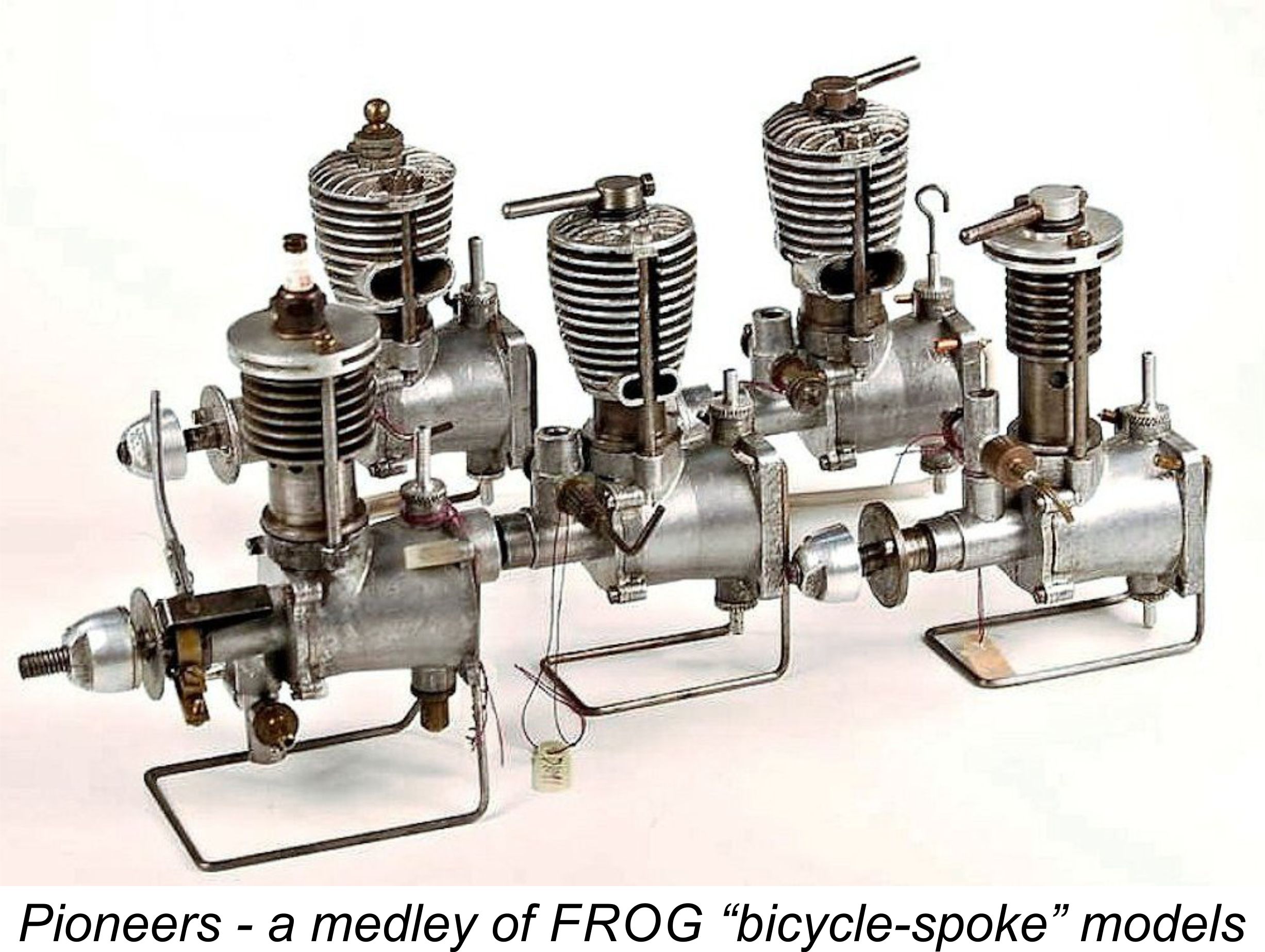 Here we examine a series of “utility-grade” British engines from the 1940’s which provided a first-class introduction to power modelling for many aeromodellers in Britain and elsewhere during the years immediately following WW2. These are the highly individualistic model powerplants produced under the “FROG” marketing banner during the early post-war period.
 of additional information was derived from the excellent 1989 book “
 “FROG” (“Flies Right Off Ground”) was the trade name of International Model Aircraft Ltd. (IMA). This company had been founded in 1931 as a partnership between Joseph "Joe" Mansour and the Wilmot brothers Charles and John. Note the clever incorporation into the company's "winged frog" logo of the founders' initials M and W, rendered for clarity in the attached image in blue and red respectively.
 The flagship brand of Lines Brothers was the world-famous Triang toy range, the triangle emblem of which represented the three Lines brothers who owned the company (three Lines make a triangle - get it?!?!). Their main toy manufacturing complex was located
 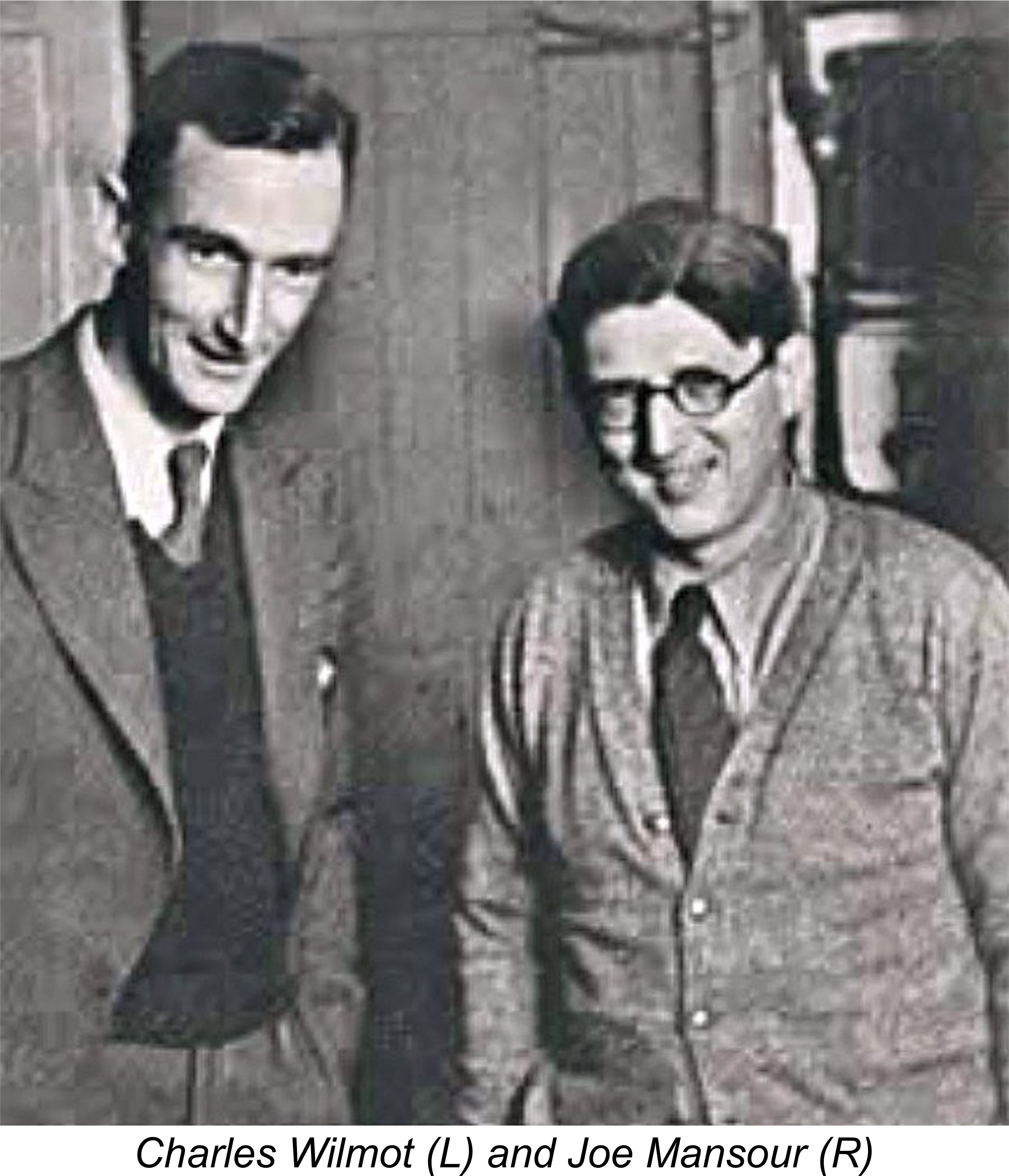 Sadly, John Wilmot perished in a motor vehicle accident in 1943. In 1944 Charles Wilmot and Joe Mansour were forced to sever their connection with IMA, reportedly as a result of some irregularities in the subsidiary company’s book-keeping. They were apparently not directly involved in this matter but were forced to accept ultimate responsibility due to their positions as Directors - a high-minded concept of Director responsibility notably lacking in today’s “pass-the-buck” business world (to say nothing of politics!). Following the war, the two surviving members of the original partnership re-commenced trading under the Wilmot, Mansour name, going on to develop the famous Jetex series of compact solid fuel model jet engines and associated models.
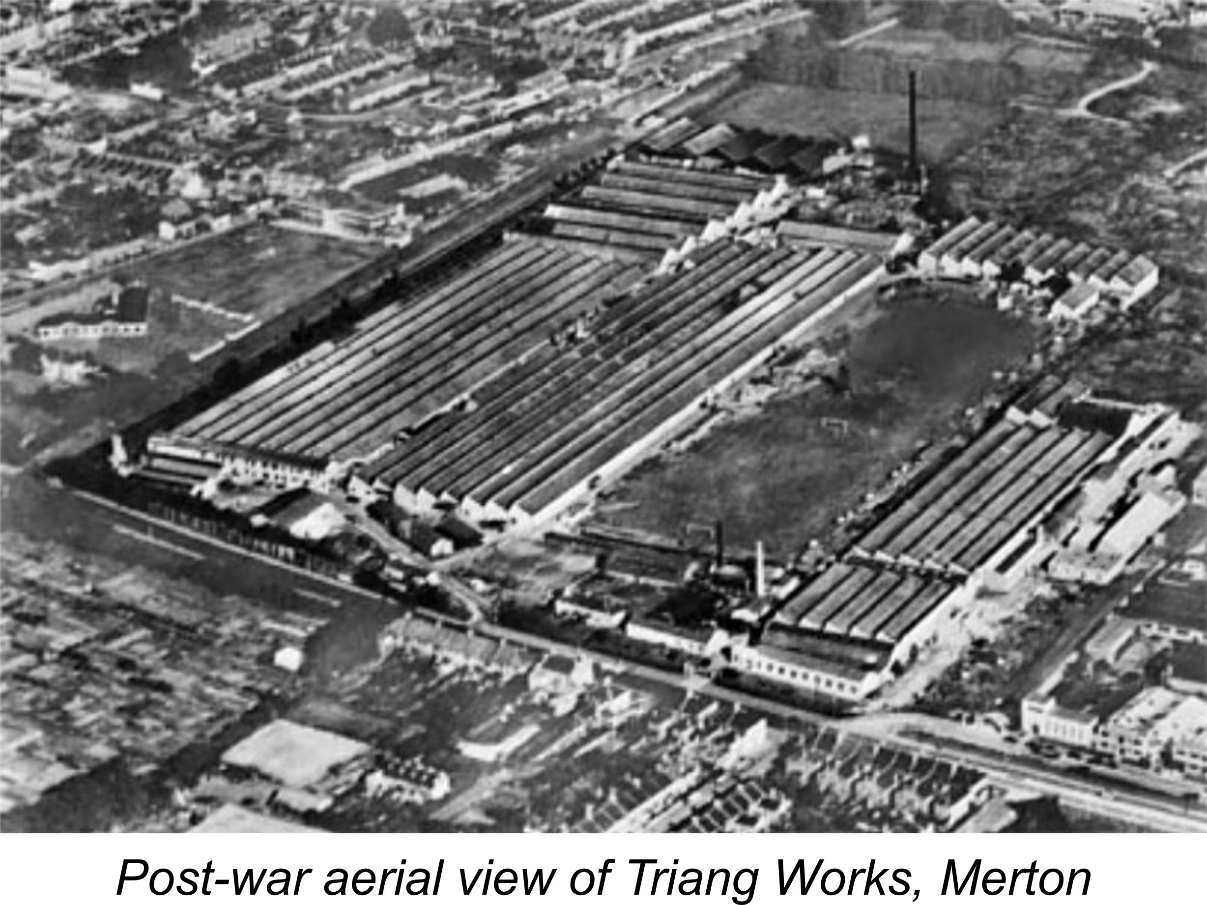
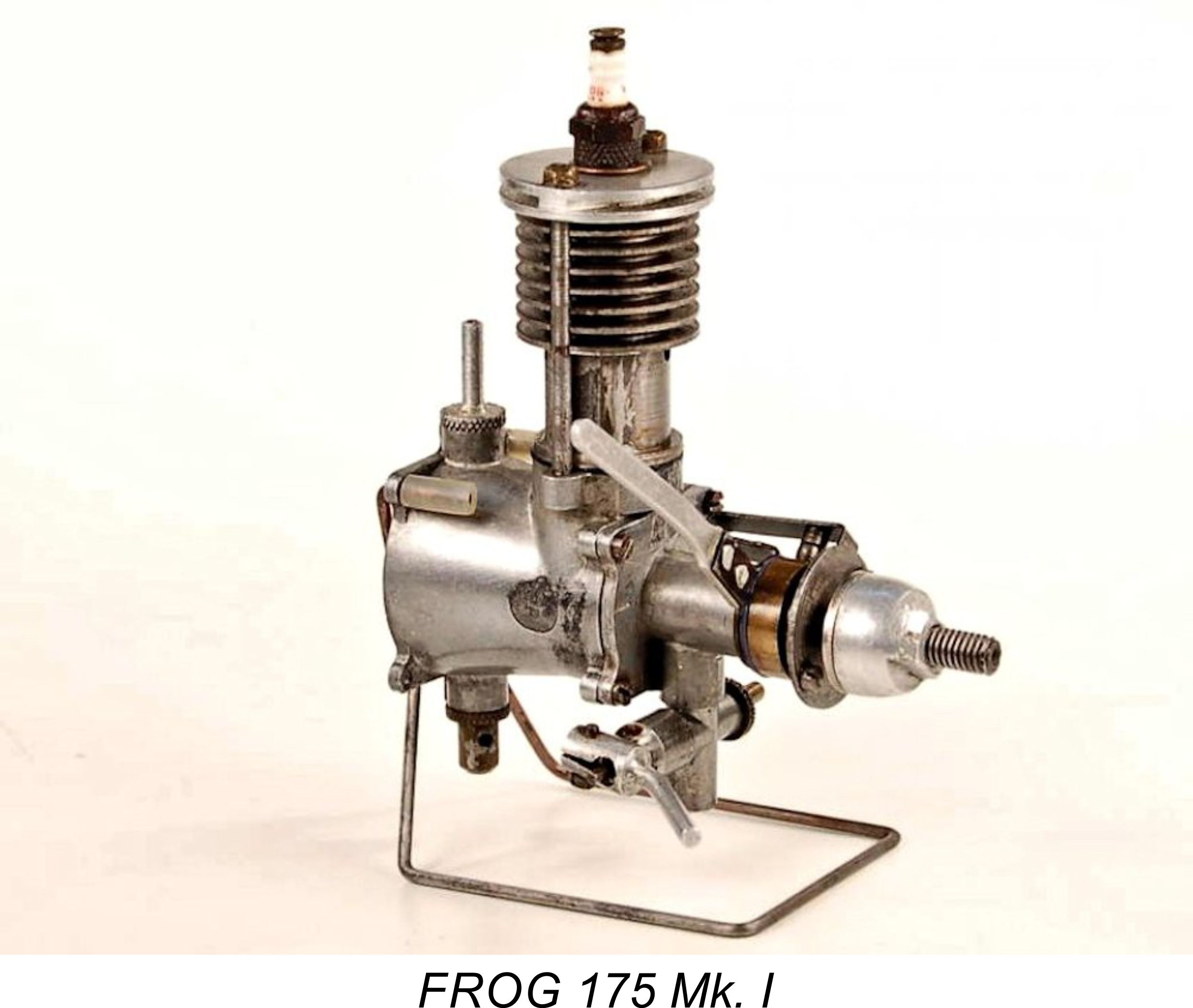 The FROG model engine range was introduced quite soon after the conclusion of WW2 with the early 1946 appearance of a 1.75 cc spark-ignition engine known appropriately enough as the FROG 175. This model was in fact one of the first new commercial model engine designs to appear on the British market in the post-WW2 period.
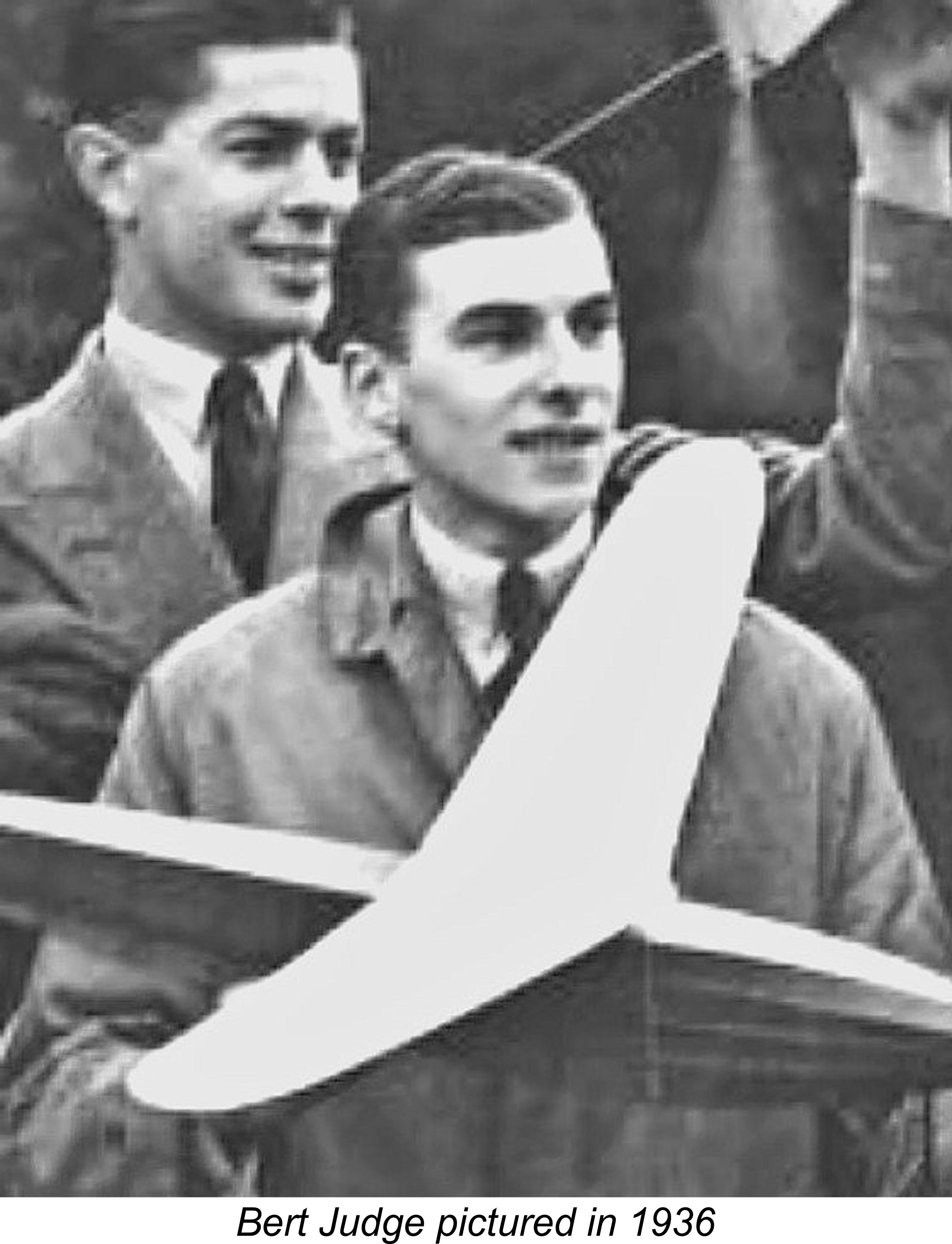 The manufacture of model engines was an activity which was highly distinct from IMA’s previous production programs. It is therefore greatly to the credit of 1936 Wakefield Trophy winner A. A. “Bert” Judge, who had been with the company since 1936 and was put in charge of the post-war engine manufacturing program, that the company’s entry into this new market area was such an immediate success.
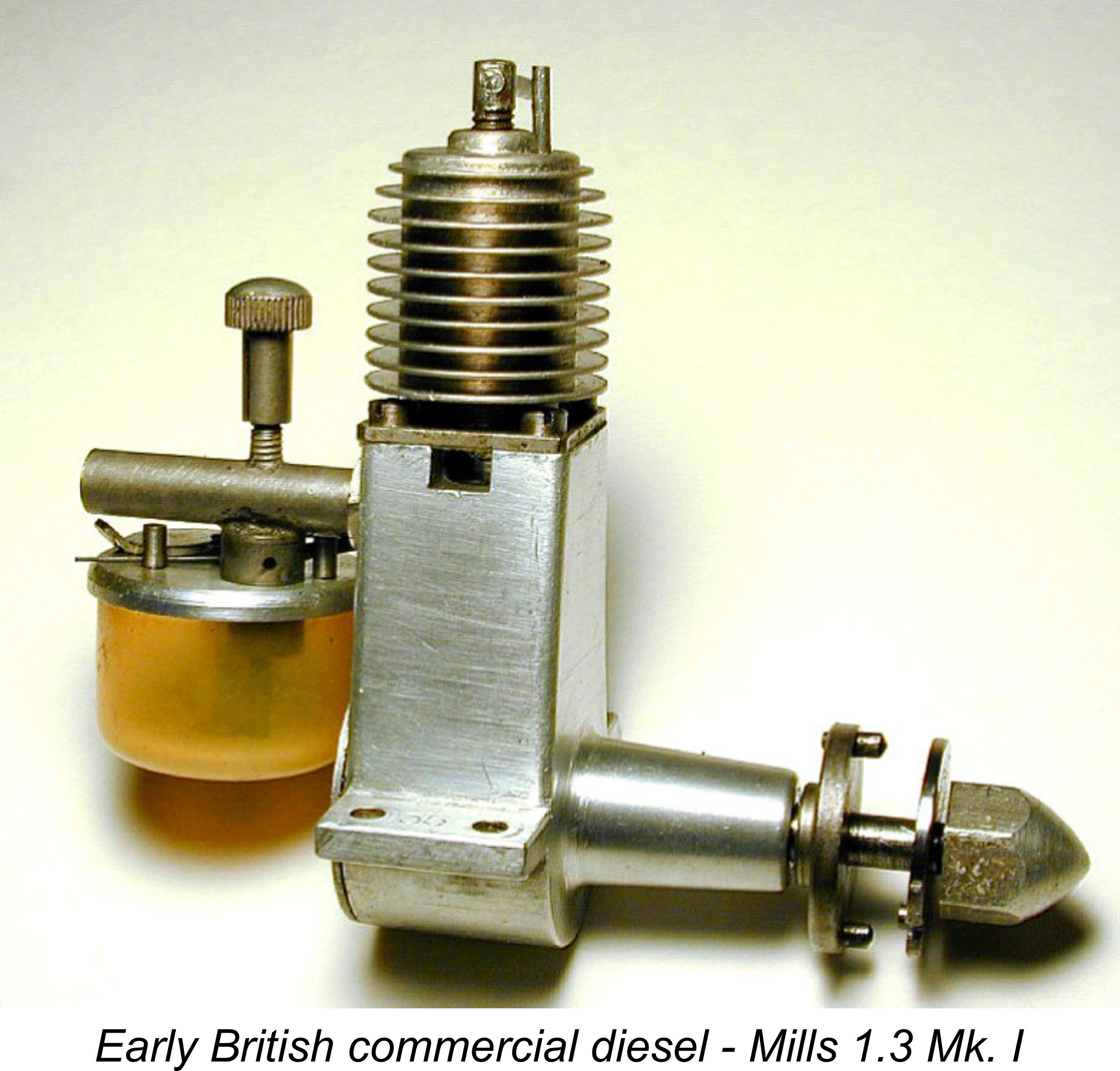
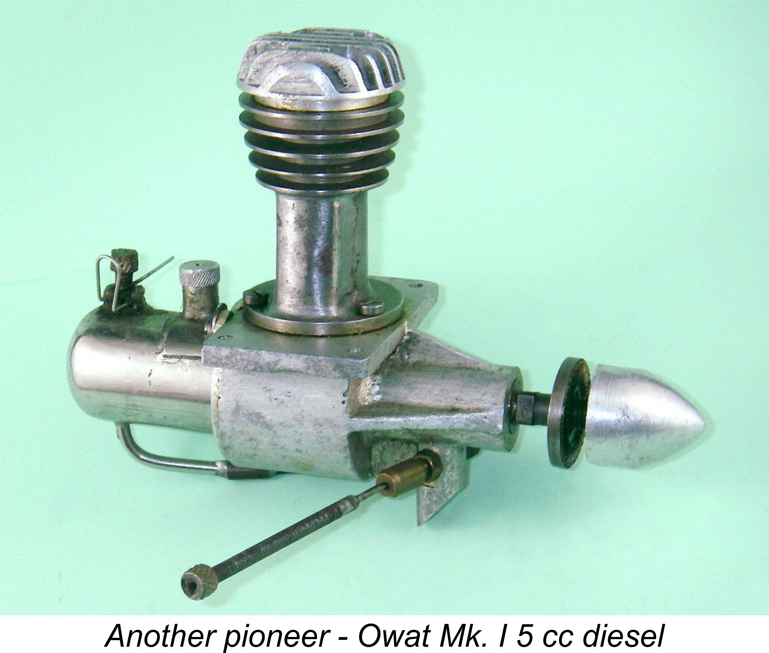
 Maxim made good on his estimate. By mid-1894, he decided that his machine was ready for initial testing. On Tuesday, July 31
 In keeping with this goal, the intention was that the test runs would be made with the aircraft remaining connected to the rail system while hopefully lifting itself off the track by a few feet. However, on its third test run the crew, consisting of Hiram Maxim and Crayford mechanics Tom Jackson and Arthur Guthrie, found themselves lifted with such force that their plane broke away from the rail system and took to the air in unrestrained (and unplanned!) flight.

 In 1945, the elder George undertook the development of what was to become the FROG 175 spark ignition model. Some years ago an example of what appears to be a prototype of this engine was acquired by my friend Miles Patience and his late father. The engine in question was based upon sand-castings as opposed to the die-castings used in the production models, also displaying a number of detail differences. A
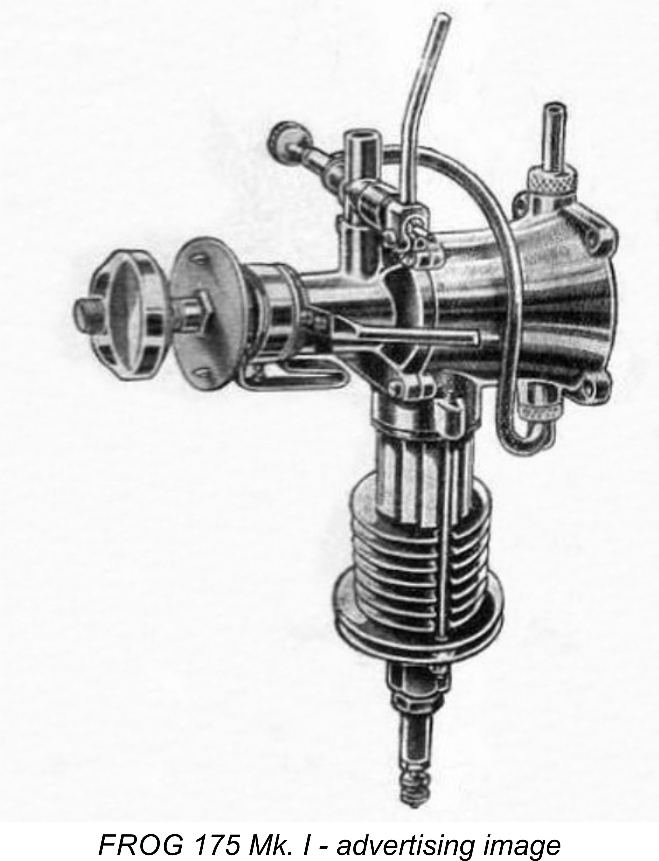
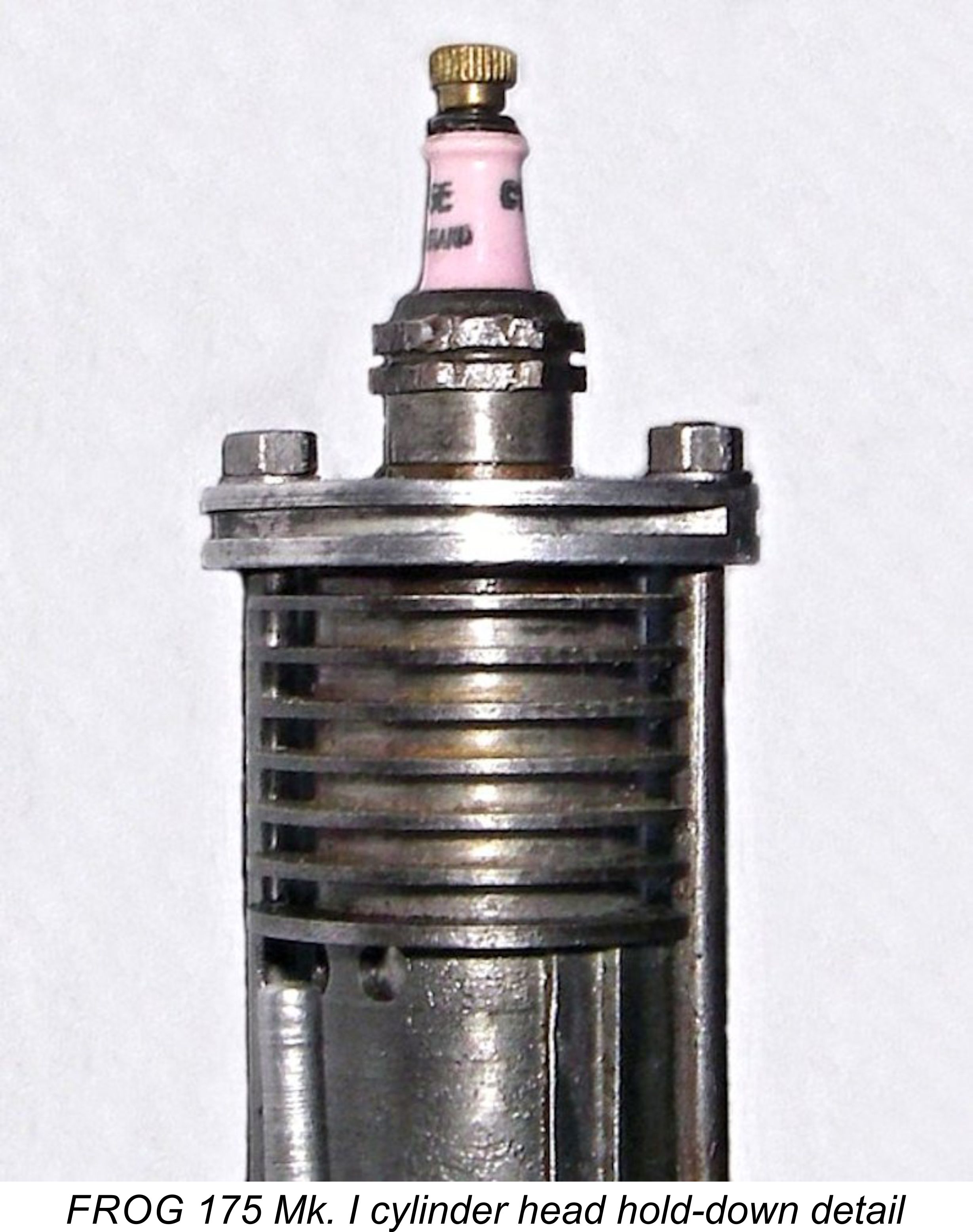
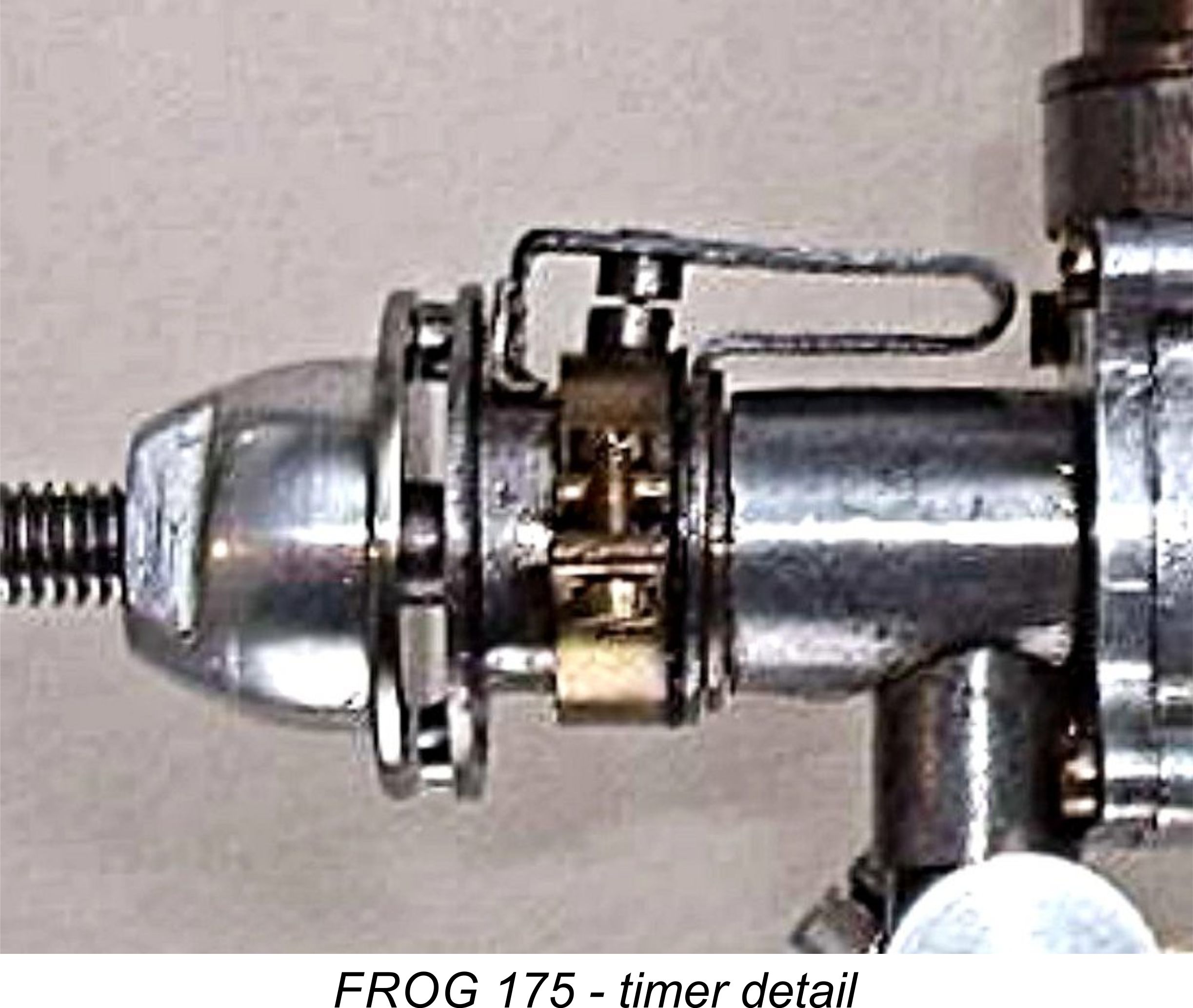 The open-frame timer was mounted in the usual manner on a machined boss at the front of the main bearing, the cam being formed as an integral feature of the rear of the hardened steel prop driver. This in turn was located on a milled square-section portion of the shaft using a matching square-section socket formed in the rear of the prop driver. A bronze thrust washer (often missing on surviving examples) was inserted between the rear of the prop driver and the face of the main bearing. The timing relationship of the cam to the shaft was thus securely fixed during use, but the “running” position of the timer arm could be varied to suit different installations simply by relocating the prop driver in any one of four positions on the shaft - a useful feature.
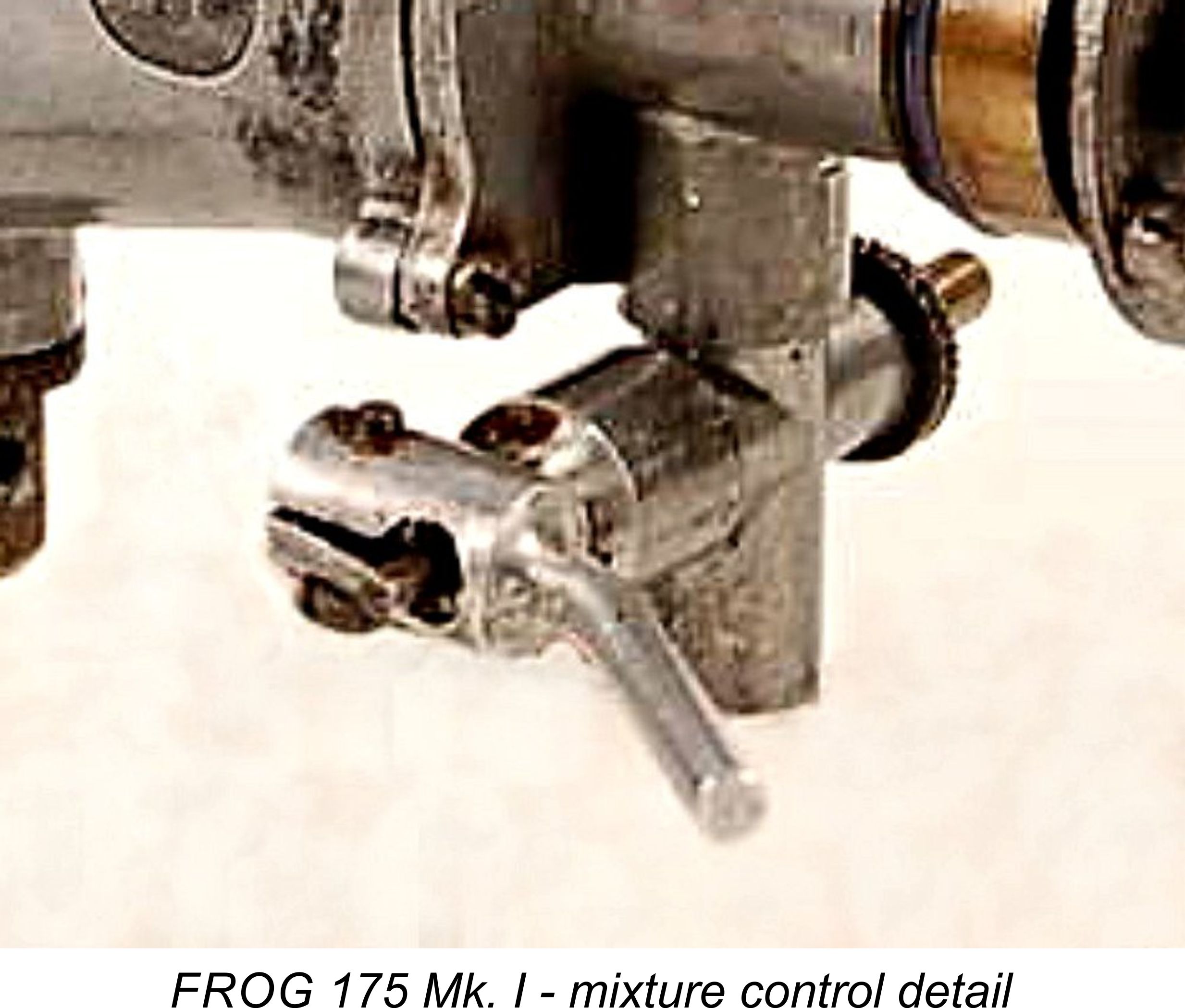 feature was the means of adjustment. The needle was located inside a small-diameter split extension of a large-diameter internally-threaded thimble. This thimble engaged with an externally-threaded spigot formed integrally with the venturi casting. A lever with a split clamp at one end fitted over the split section of the thimble extension which housed the needle. By releasing the pressure on this clamp, the needle could be freed within the thimble extension.
 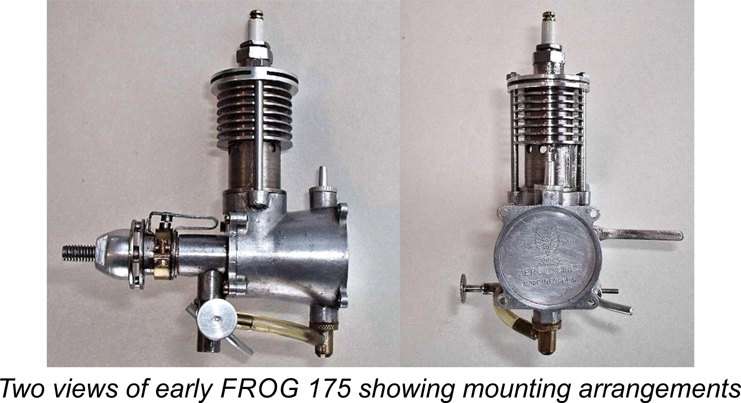 The conoidal tank mount was cast integrally with the crankcase. The tanks on the original models featured circular rear ends with four seemingly flimsy “mouse ear” style lugs to accept the screws for radial mounting. These presumably (and predictably) proved to be highly susceptible to breakage, resulting in the quick replacement of this arrangement with a sturdy square flange at the rear having four mounting holes placed at the corners.
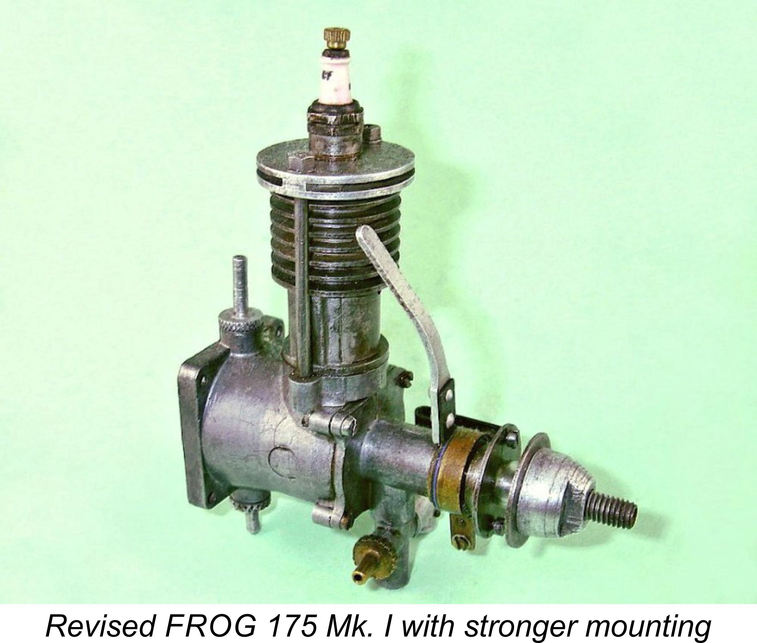
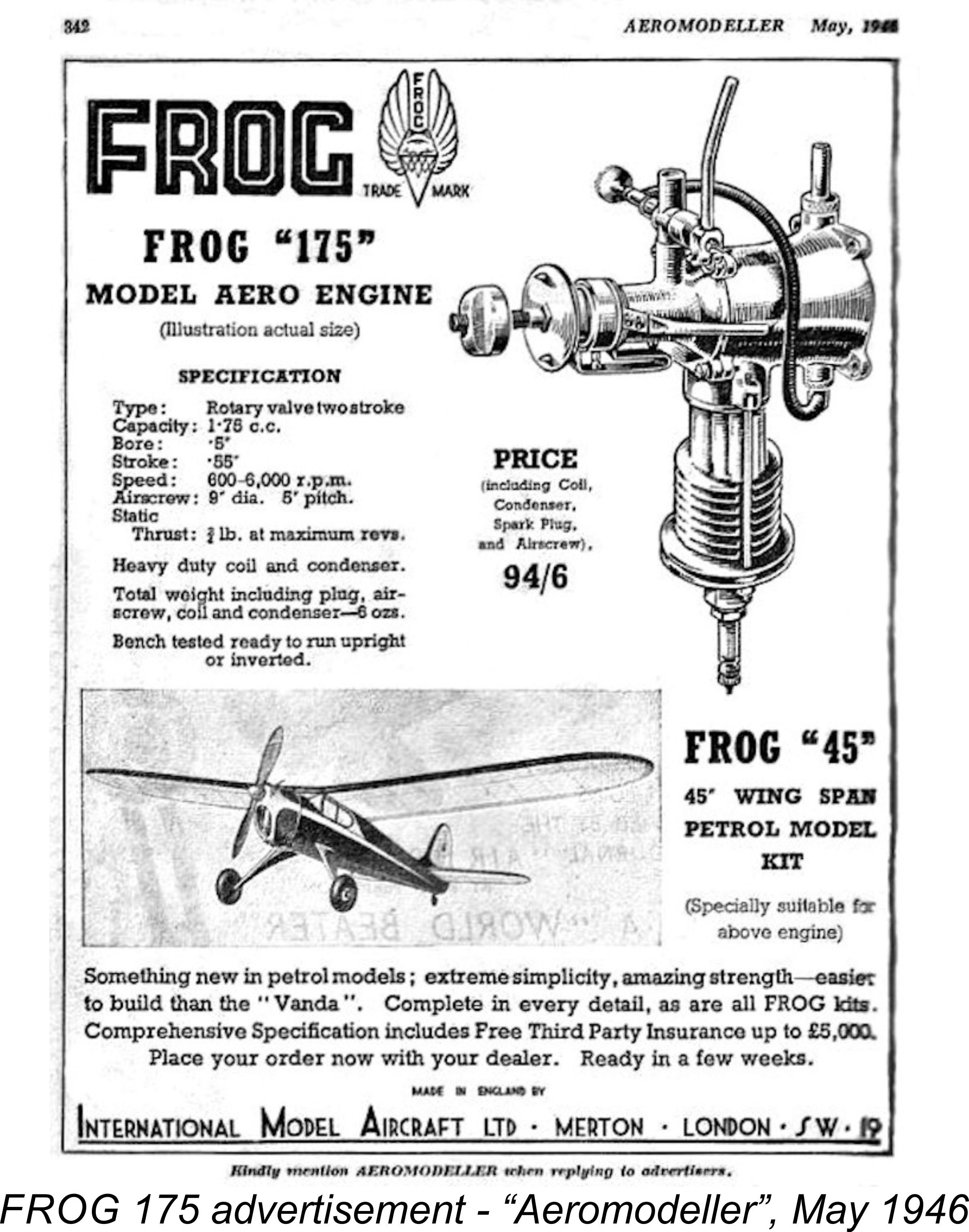 Since there was only one fuel tank vent with the system employed, it was necessary either to remove the uppermost filler spigot each time or (more practically) to invert the model when filling the tank so that the fuel tube and metering jet served as the air vent. With this proviso, the engine could be used either upright or inverted simply by switching the fuel tubing to the opposite fuel attachment point on the tank. The position of the fuel jet relative to the tank suggests that the original FROG 175 was expected to be operated for the most part in the inverted position, since in that position the needle and choke tube were readily accessible and the fuel jet was more or less in the same plane as the “full” level in the tank, thus avoiding fuel loss or flooding due to gravity drip feed.
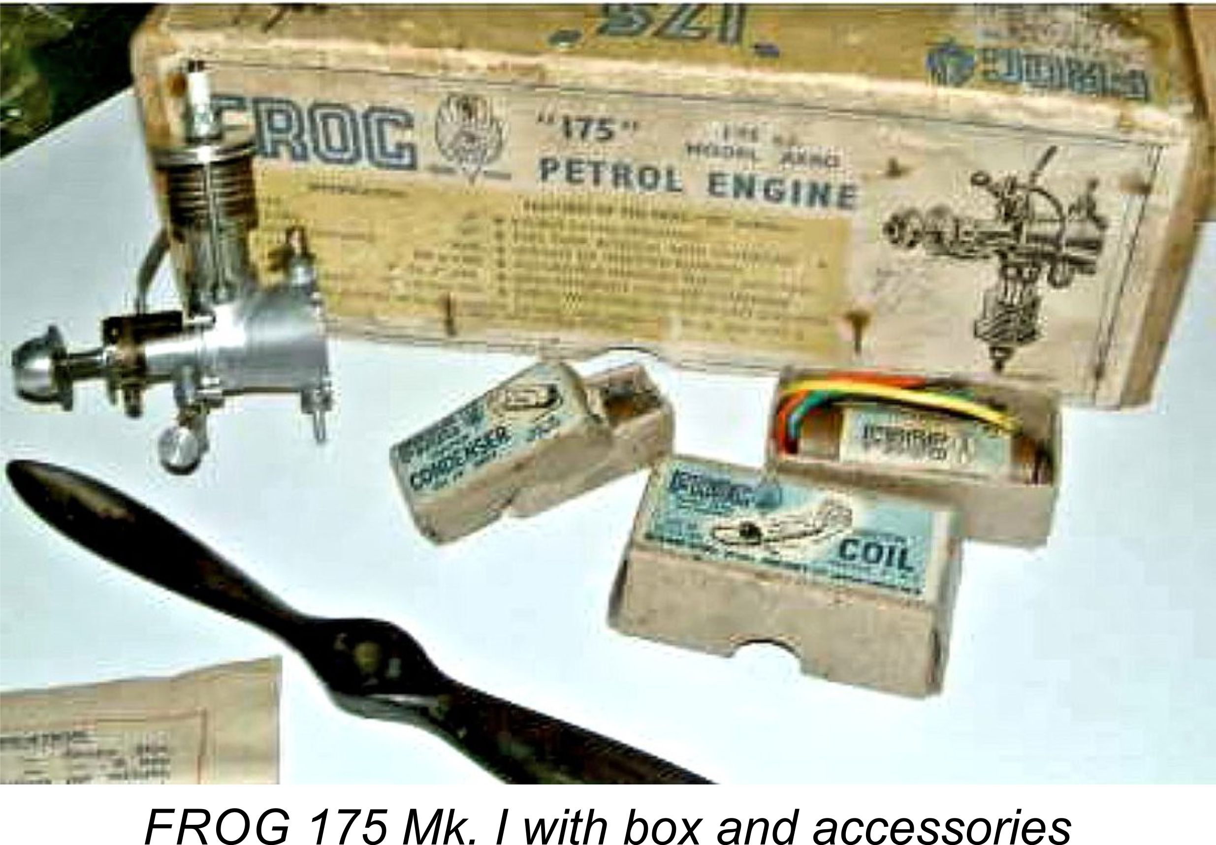 The FROG 175 was vigorously promoted in a series of full-page advertisements in “Aeromodeller” magazine, initially selling at a price of £4 14s 6d (£4.72 in “modern” money), including coil, condenser, spark plug and airscrew. The inclusion of the latter accessory required the use of a box of unusual length! By September of 1946 the price had been reduced to a highly competitive £3 15s 0d (£3.75), still including all accessories. Presumably the emerging diesel competition had something to do with this.
 There was also a somewhat obscure "marine" version of this engine which was marketed as the "Marine 175" model. In point of fact, the sole concession towards the engine's marine application was the fact that it featured a flywheel and universal joint - the cylinder and head were unchanged, with no provision for water cooling. This model was featured in advertisements for the FROG Whippet hydroplane kit, but otherwise went largely unpromoted.
  As events were to prove, the FROG 175 remained in production as the sole FROG model engine offering for some 16 months following its introduction. The fact that the engines did not carry serial numbers at this stage makes it impossible to estimate production figures with any certainty. It is known from some comments in an “Aeromodeller” advertisement in the October 1946 issue (below at the right) that machine tool and materials shortages had initially impeded IMA’s engine production program, implying that the numbers
 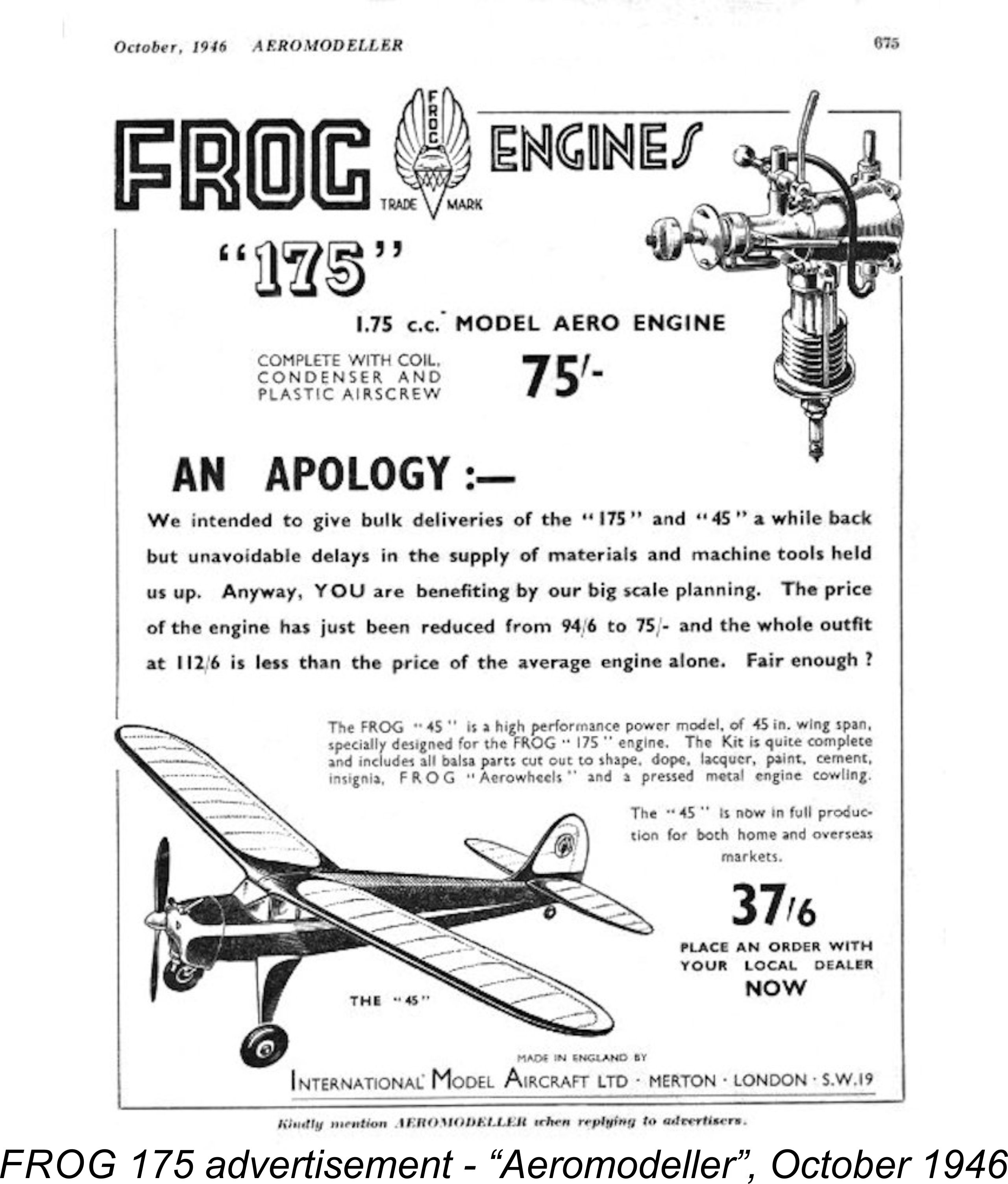 manufactured up to that point were not perhaps what IMA had intended.
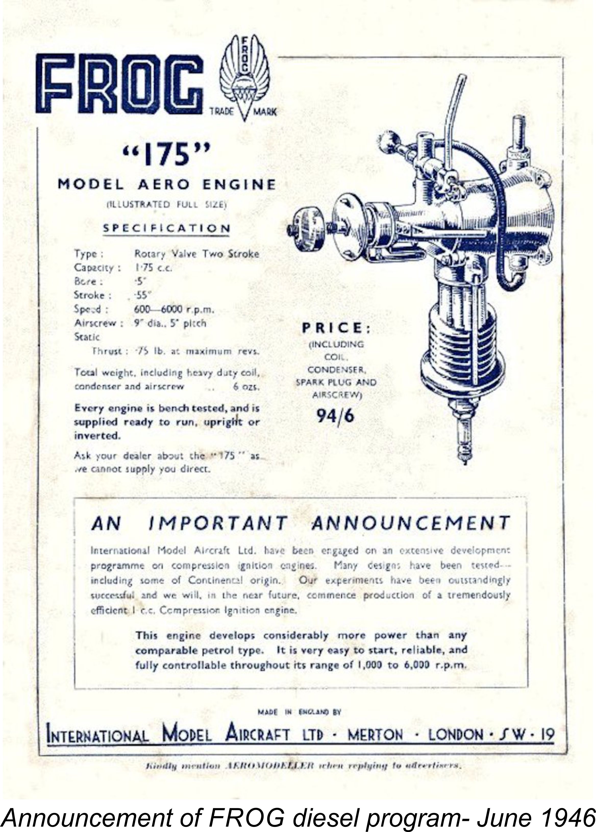

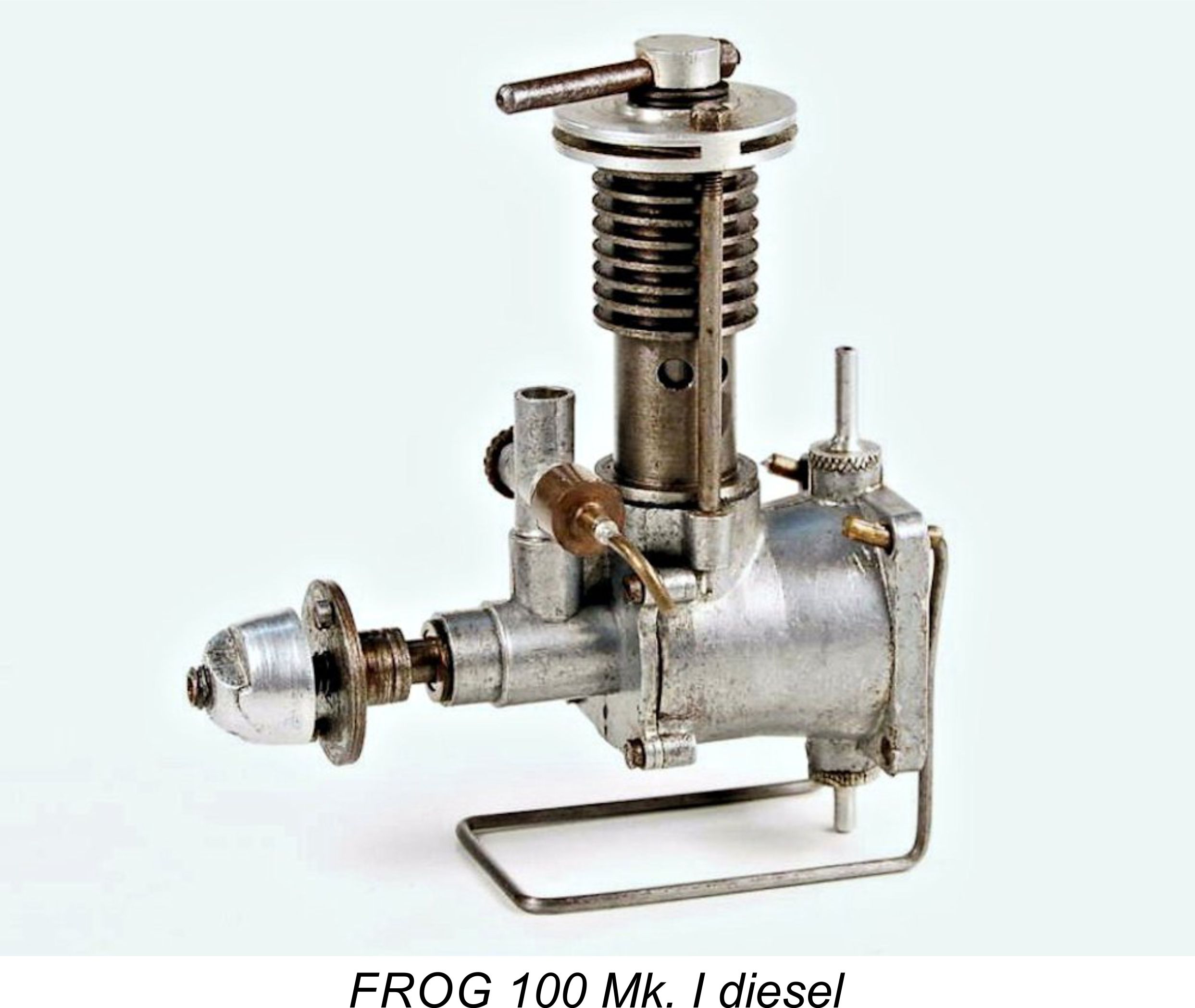 As in the case of the FROG 175 petrol engine, the FROG 100 was based on a prototype constructed by George Court, who appears in effect to have held the position of chief FROG engine designer at this early stage, albeit on a freelance basis outside of his regular employment with Vickers. It was seemingly this engine that had been demonstrated by Court to his North Essex clubmates in late 1945, as mentioned earlier.
  Despite the relatively poor quality of the reproduced image, it is possible to see that the design of this prototype departed quite significantly from that of the production version of the engine which appeared in due course. Readily apparent features which were not retained include the lack of fins, the external transfer passage at the front (possibly accompanied by a similar one at the rear?!?), the lack of an integral fuel tank and the use of a strap for retaining the cylinder that wraps around the bottom of the crankcase. Weird, or what?!? However, the head looks the same, right down to the slots cut into the head disc. As Maris points out, these slots appear to represent a waste of production resources from which no readily discernable benefit is apparent.

 The previously-reproduced advertisement in the June 1946 issue of "Aeromodeller" confirms that the development of the two prototypes used by the Courts at Heston was undertaken with the full knowledge and sanction of IMA. There’s no doubt that such a convincing and well-publicised demonstration of a successful and readily practicable diesel version of their established spark ignition design could only have enhanced the enthusiasm of IMA for the diesel project. The July 1946 release of the
 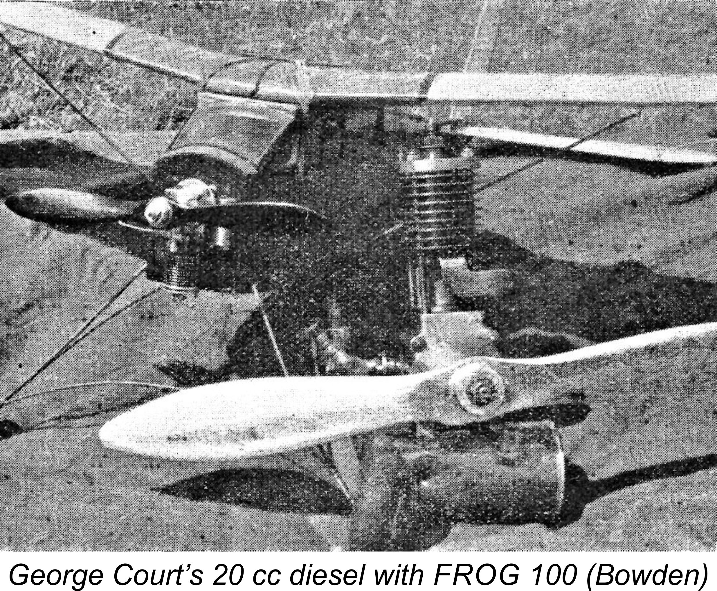 George Court was not one to allow a setback like this to put him off his stroke, nor was he willing to stop at the 1 cc displacement figure - he was clearly keen to probe the extremes!! In his 1947 book “
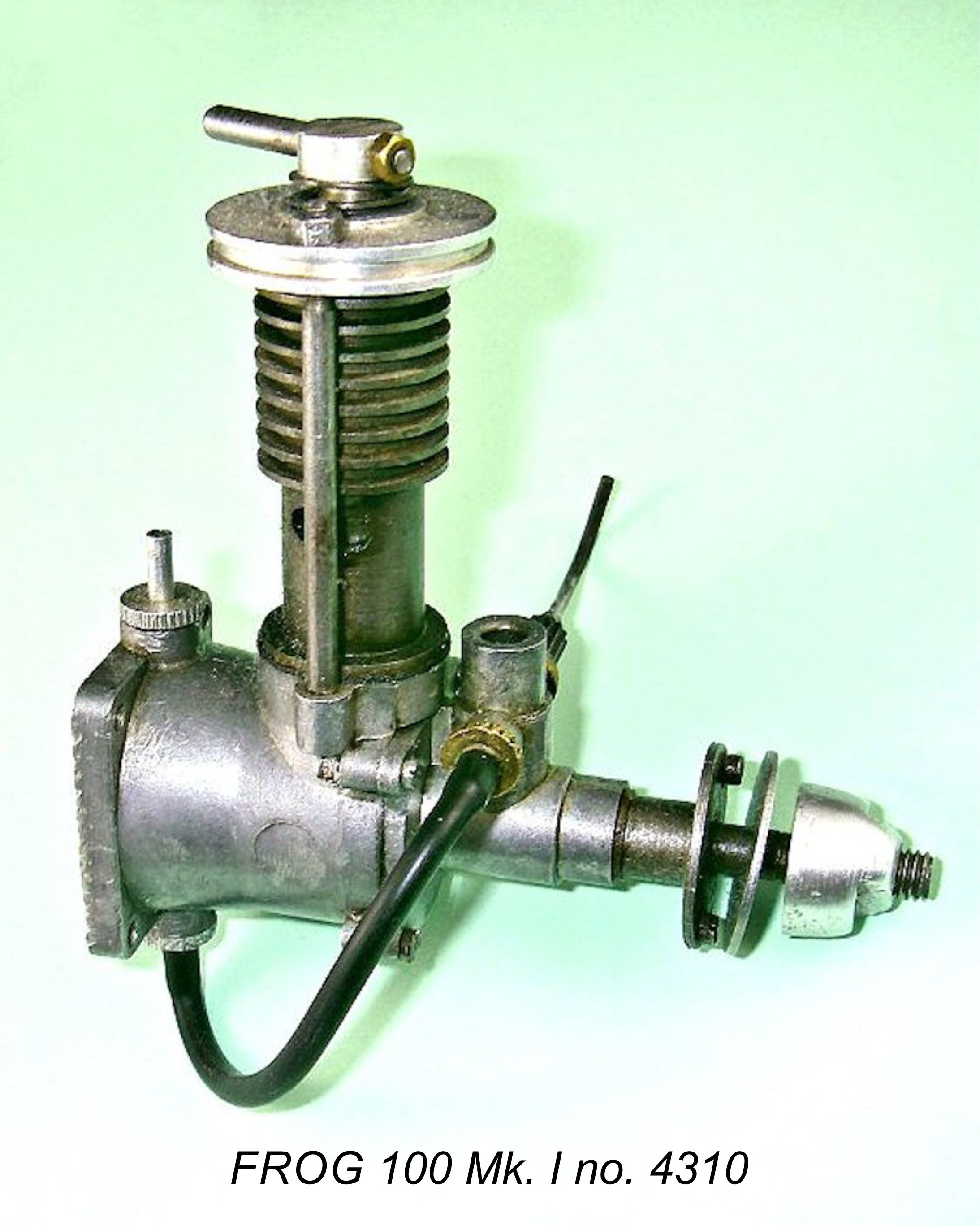 The material of the cylinder was changed from steel to Meehanite in the new diesel model, while the piston continued to be made as before of Meehanite. This actually constitutes one of the Achilles Heel’s of these engines, since a Meehanite-in-Meehanite piston/cylinder combination is not notable for having long-wearing qualities. The early
 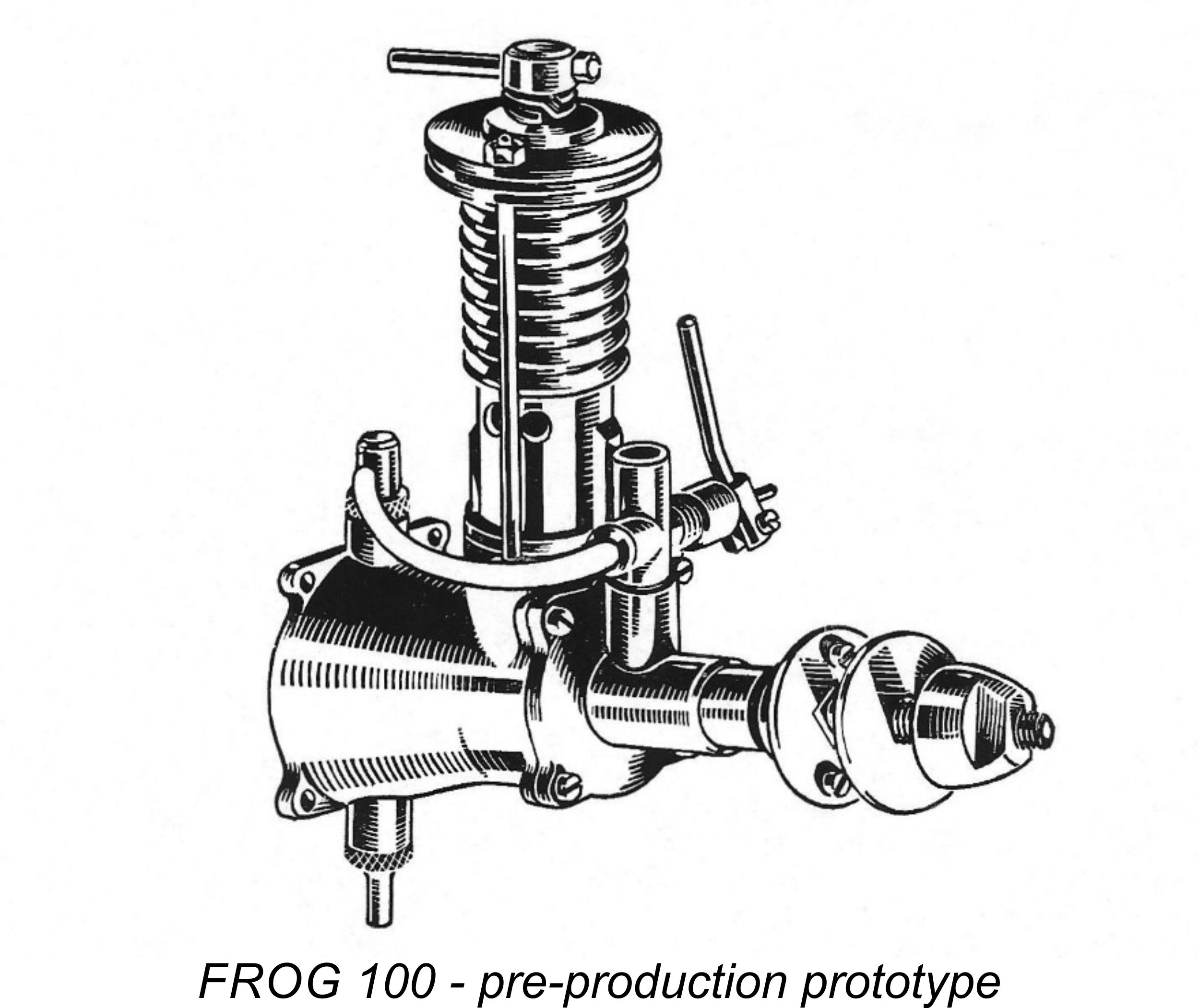 ased on the promotional illustrations, the very earliest prototype examples of the FROG 100 from late 1946 seem to have shared the circular rear mounting surface and flimsy “mouse ear” lugs that were employed on the original FROG 175 sparker. However, no engines appear to have been manufactured for sale in this configuration - I have yet to run across even a reported example. Those encountered today invariably feature the far stronger square tank back used on the later examples of the FROG 175. It’s likely that some left-over 175 cases having the circular tank back were used on the 1946 diesel prototypes and that one of these was used as the model for the original advertising illustration. As stated above, the design of the radial mount backplate had undoubtedly been changed on the companion 175 model at some time well prior to the commercial release of the FROG 100. The production version of the new diesel model very logically used the same main casting.
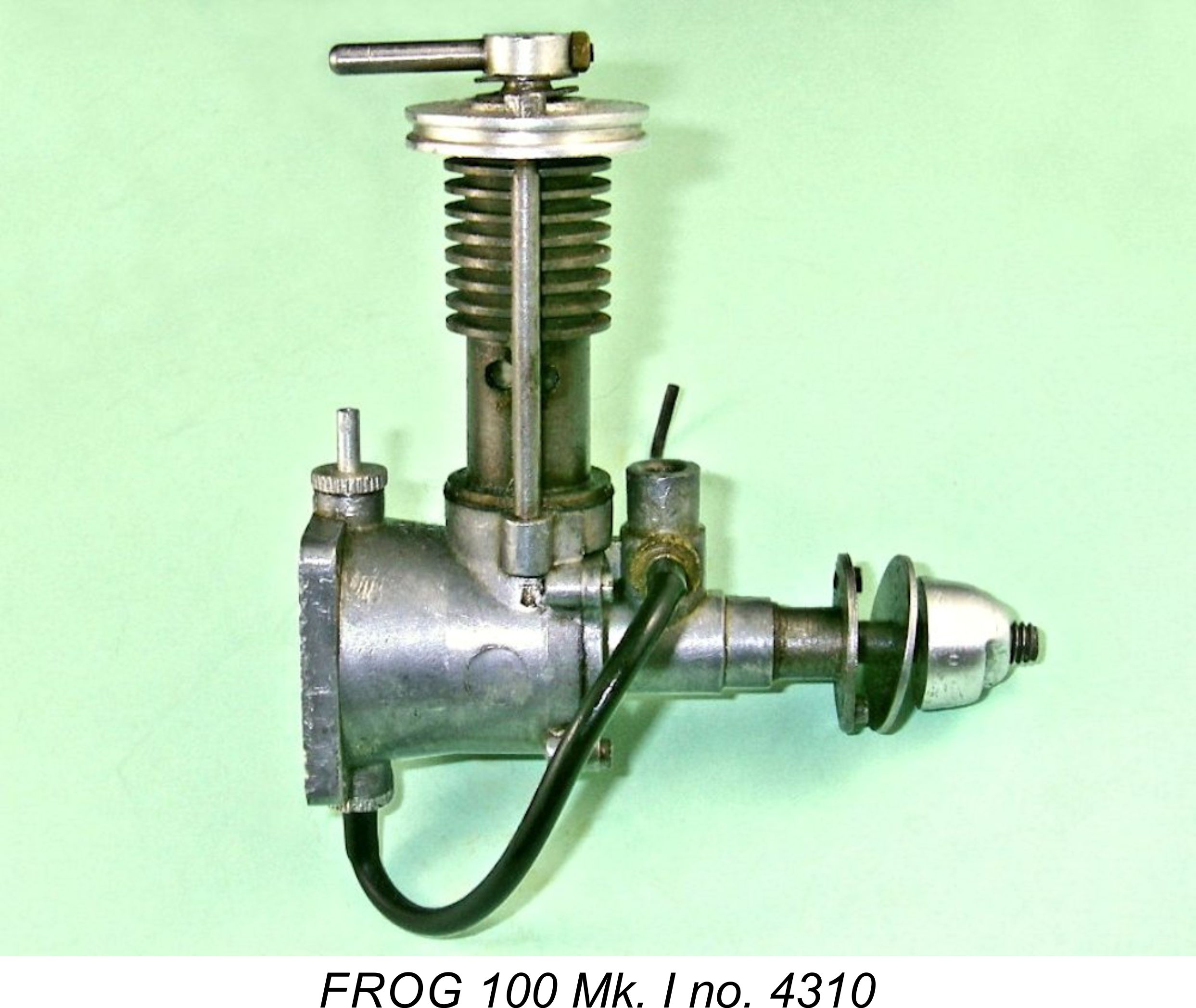 Apart from the absence of a timer and the provisions for compression ignition, the FROG 100 was structurally very similar to the 175 model, retaining the radial tank mount, the integral cooling fins, the disc-style cylinder head, the circular-flanged lower cylinder and the retention of the entire cylinder assembly solely by the two nuts on top of the cylinder retention studs. The head seal in this case was of course provided by the contra-piston, so the issue of over-tightening of the nuts to ensure an adequate seal naturally did not arise - the head only retained the dual functions of holding the cylinder in place and accommodating the compression screw. The engine featured a Thackeray washer (a spring made of flat steel with only a few windings) between the compression vernier and the head which effectively helped to prevent compression run-back - a worthwhile feature which was carried over to the later diesel models. Interestingly, the thread used for the composite compression screw was once again the spark-plug standard of ¼-32 UNEF.
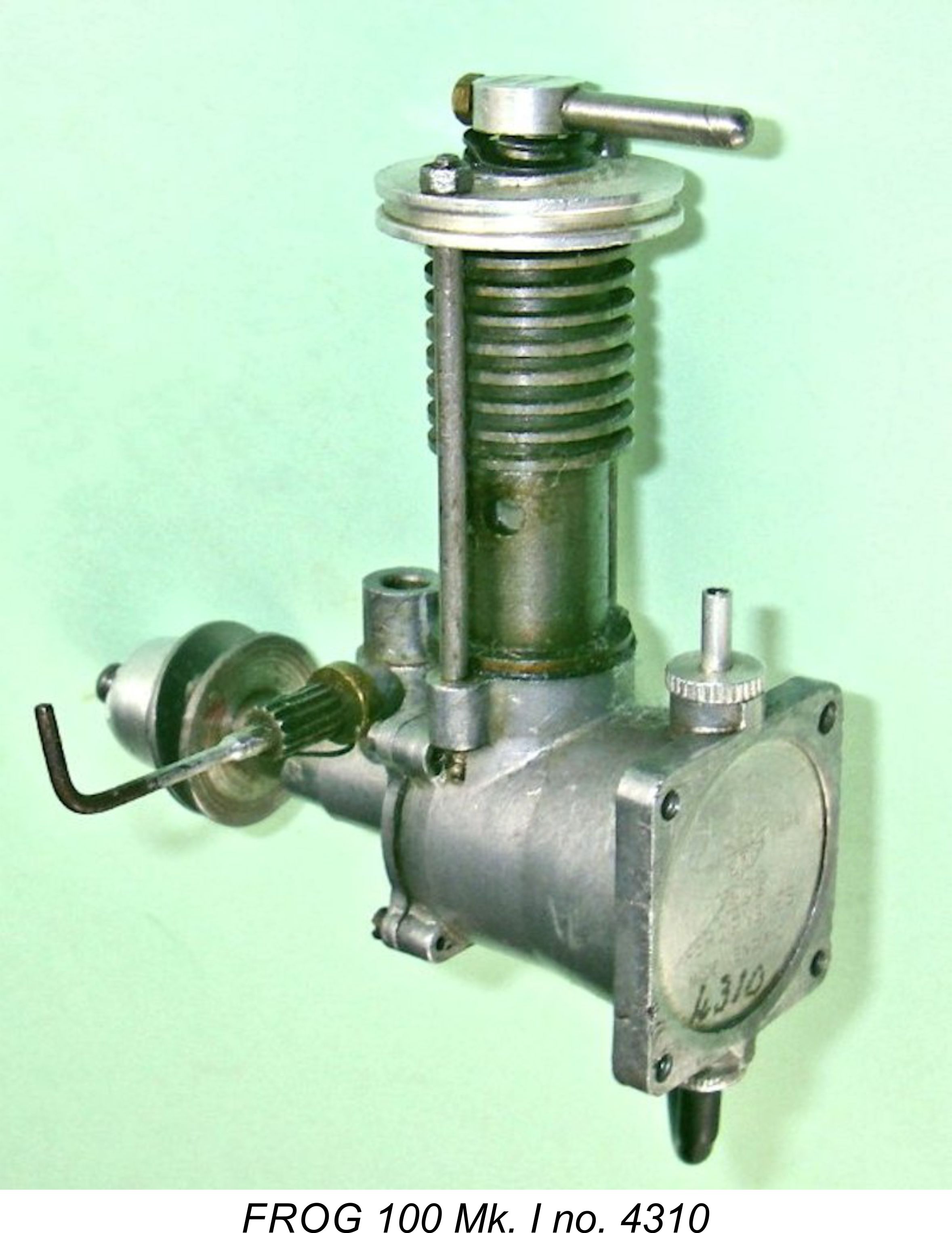 The original FROG 100 initially used the same rather complex needle valve employed on the 175 spark ignition model. The surface jet fuel supply system was also retained. However, at some intermediate stage during the production life of this model the design of the mixture control system was changed to a conventional serrated steel thimble which was soldered onto the needle and was tensioned by a wire spring clip. In other words, a totally conventional surface jet needle valve system. This arrangement was to be retained for all subsequent models in this series. It has to be said that it is far less finicky in operation.
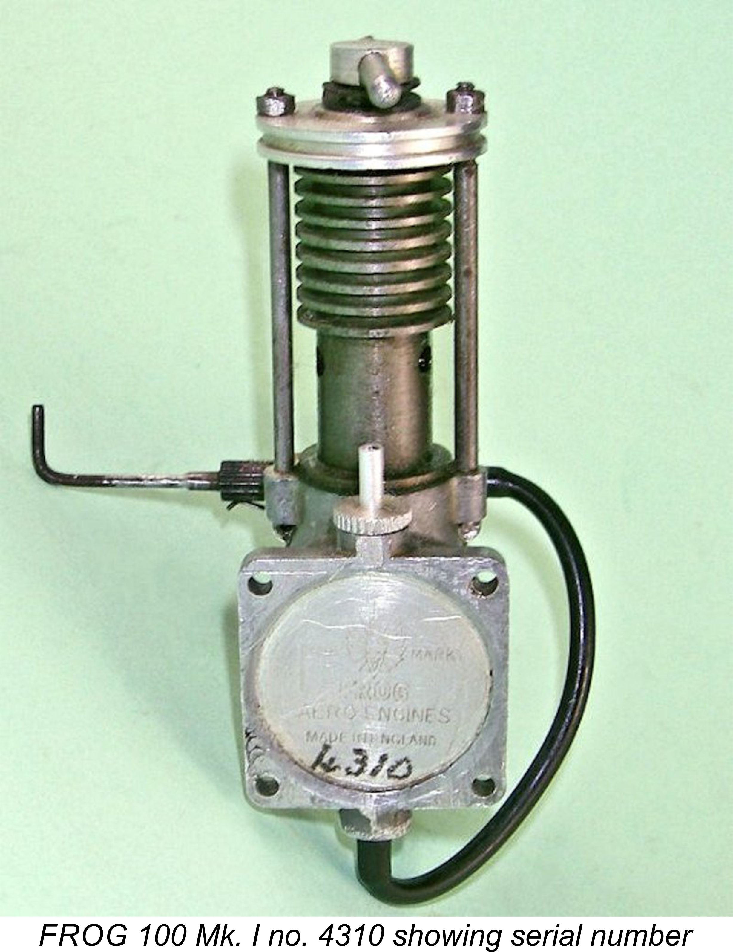 Another innovation that appeared at this time was the application of serial numbers to the FROG range. The FROG 100 diesels were numbered from the outset, while the 175 sparker thenceforth carried serial numbers as well, as did all subsequent members of the “bicycle spoke” series. During the approximately 16 month period prior to the introduction of the FROG 100 when only one model was being produced, it probably seemed unnecessary. However, the simultaneous production of two distinct models based on the same castings would logically have made some form of distinction appear advisable.
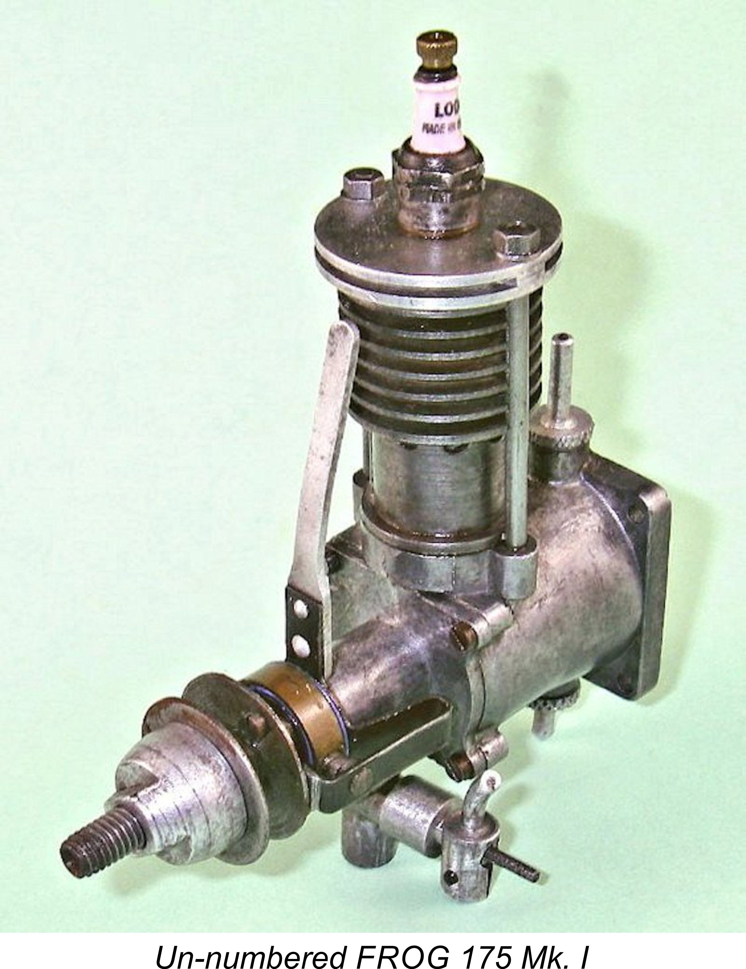
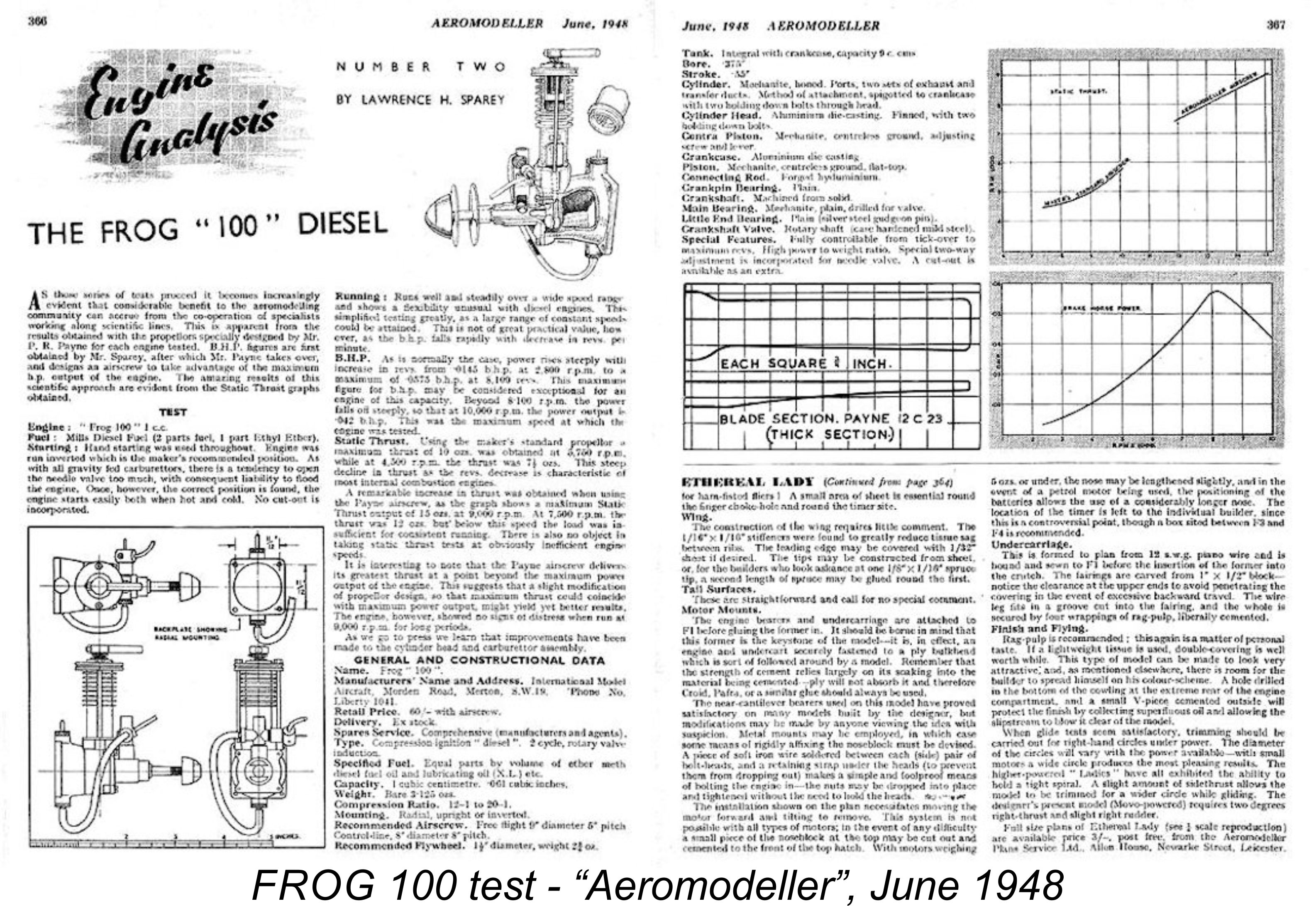
 Despite the unfavourable outlook for the FROG 175 spark ignition model as 1947 drew to a close, the company did not immediately give up on that unit. In early 1948 the first of two successive revised variants of the 175 made its appearance. Once again, it utilized the same lower end components as its predecessor but was extensively redesigned as far as the cylinder went.
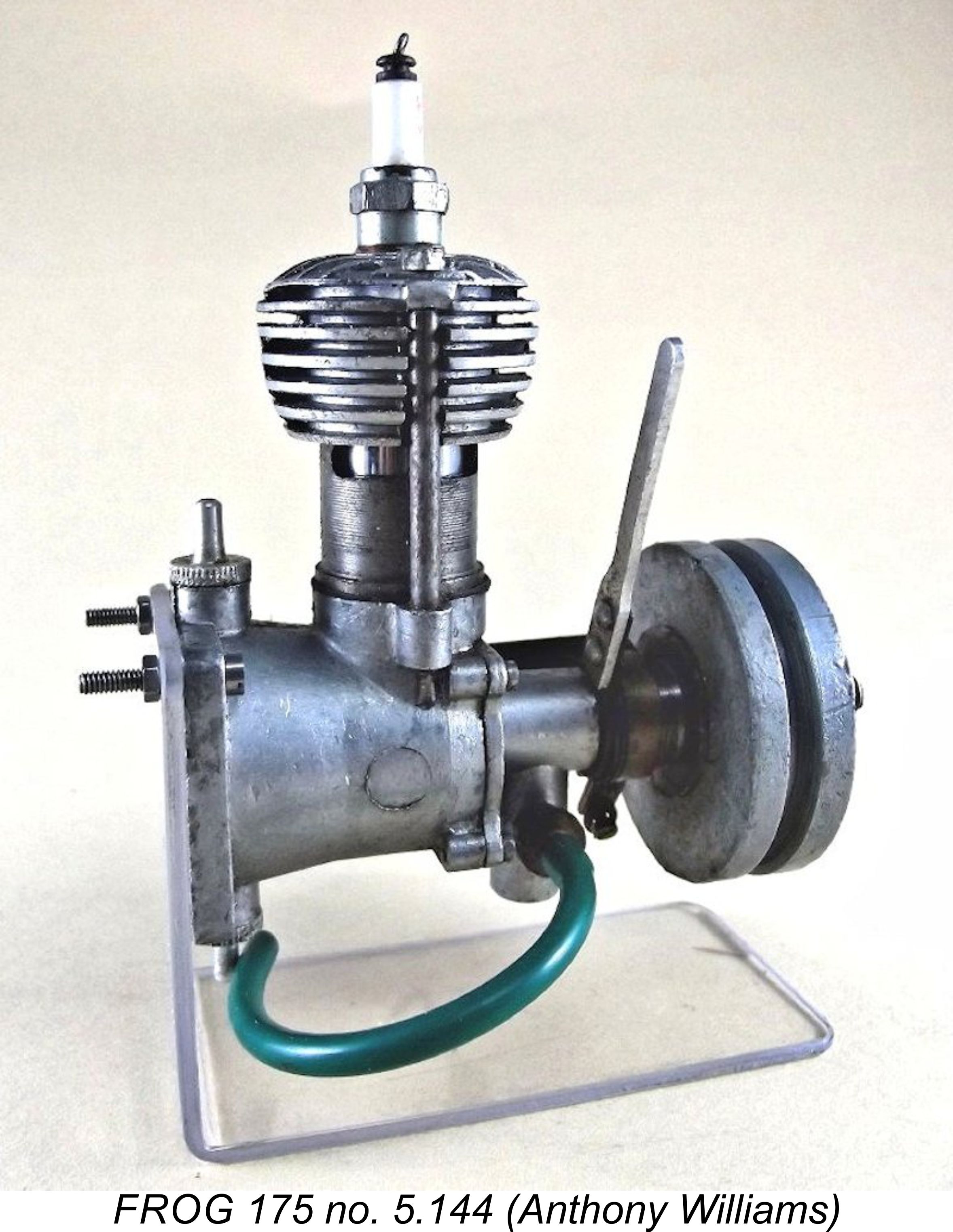
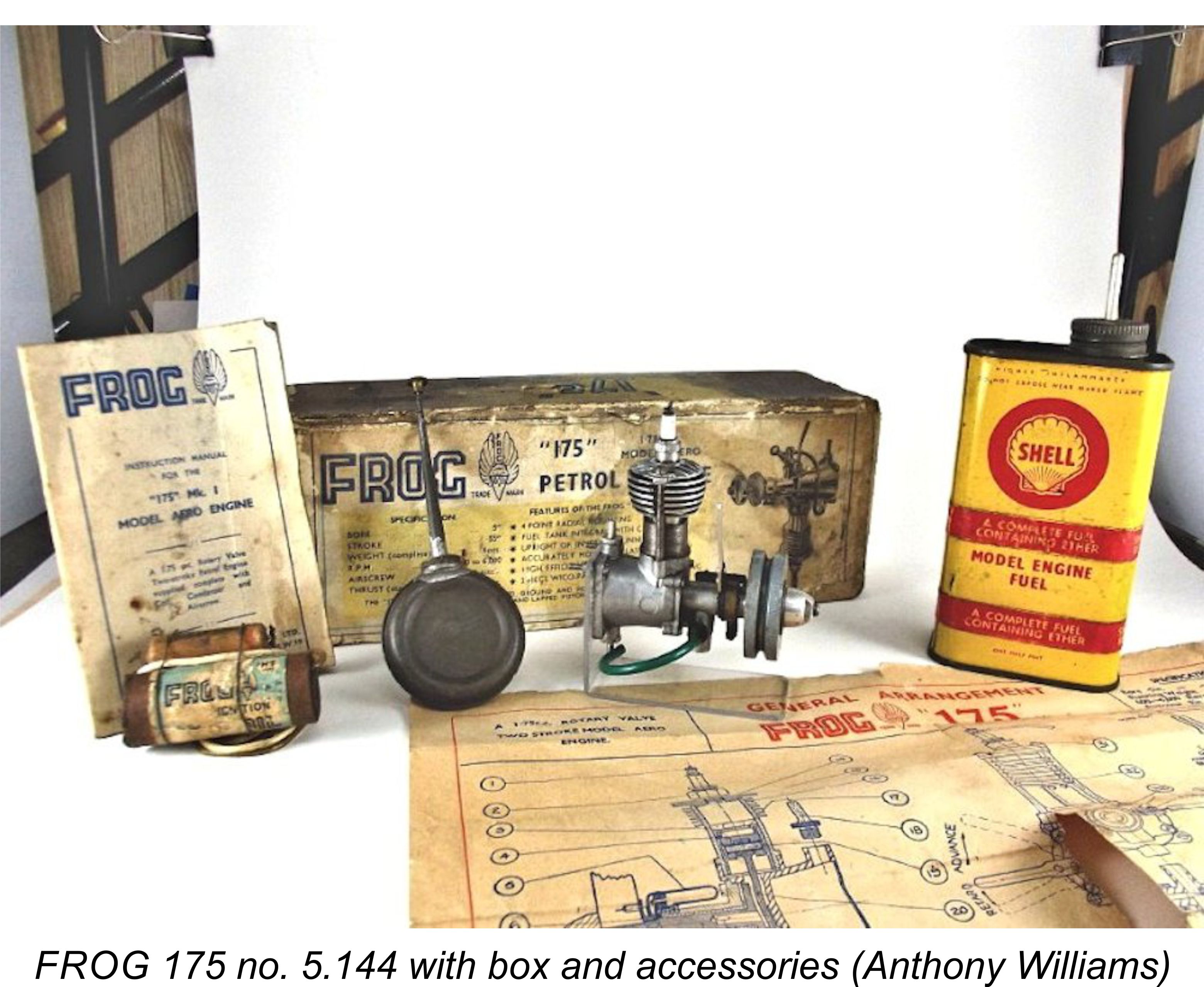
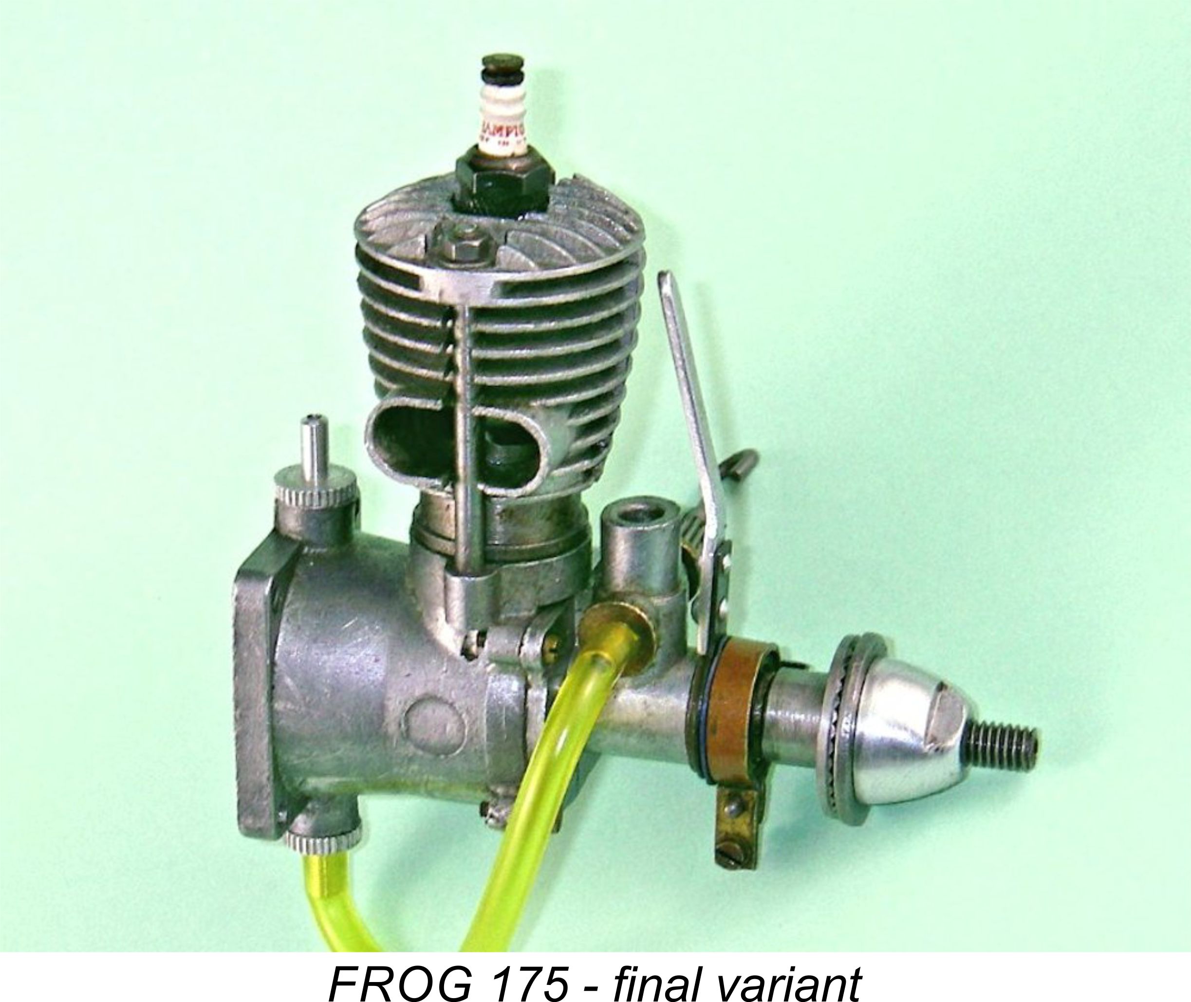
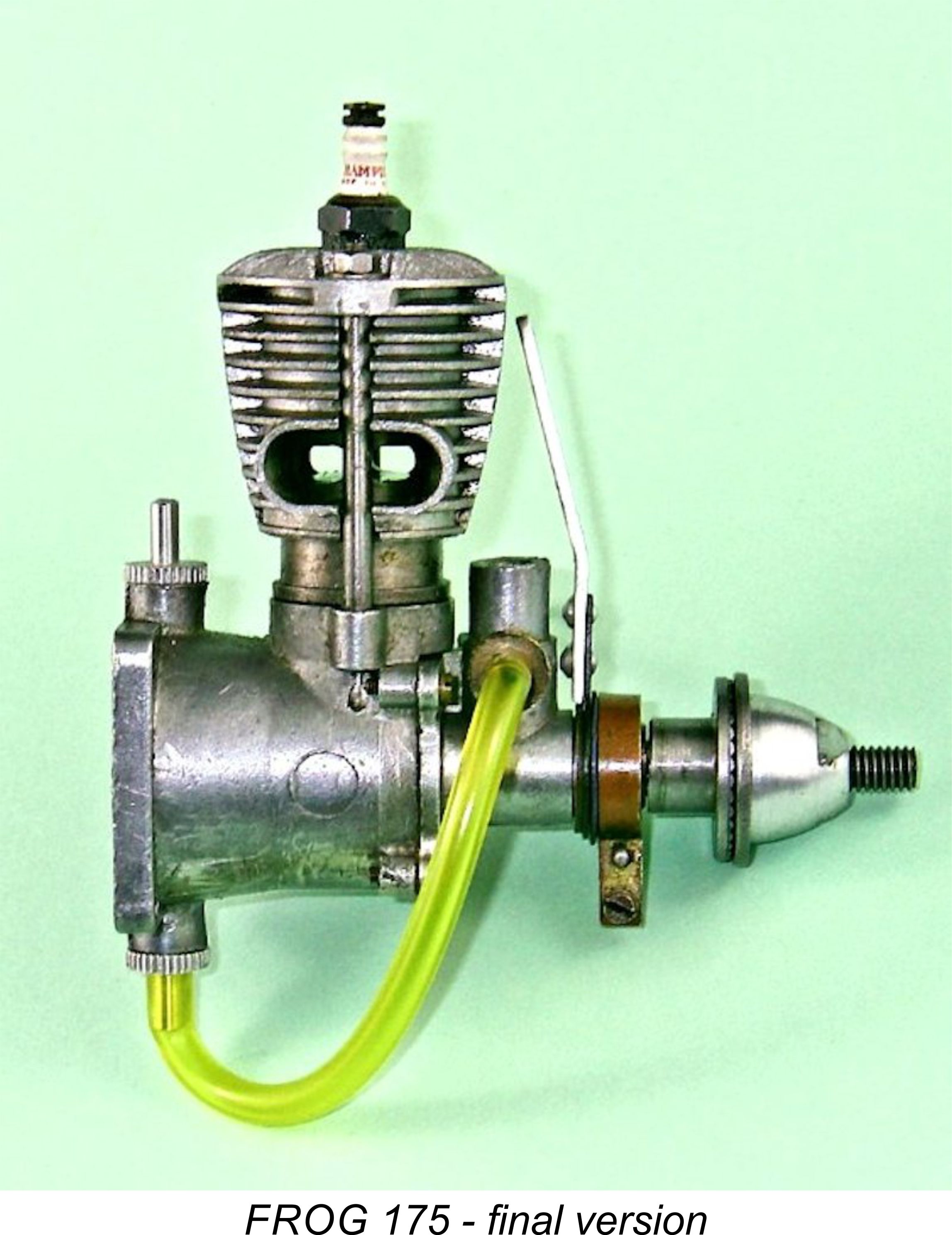
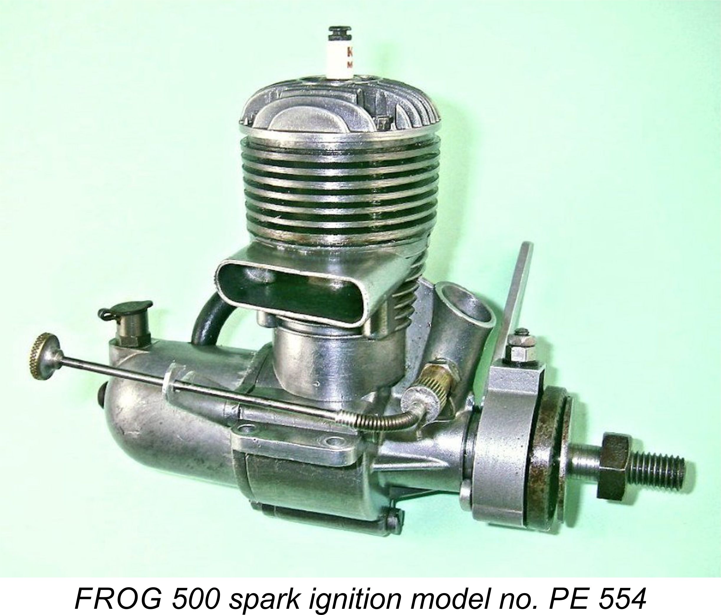


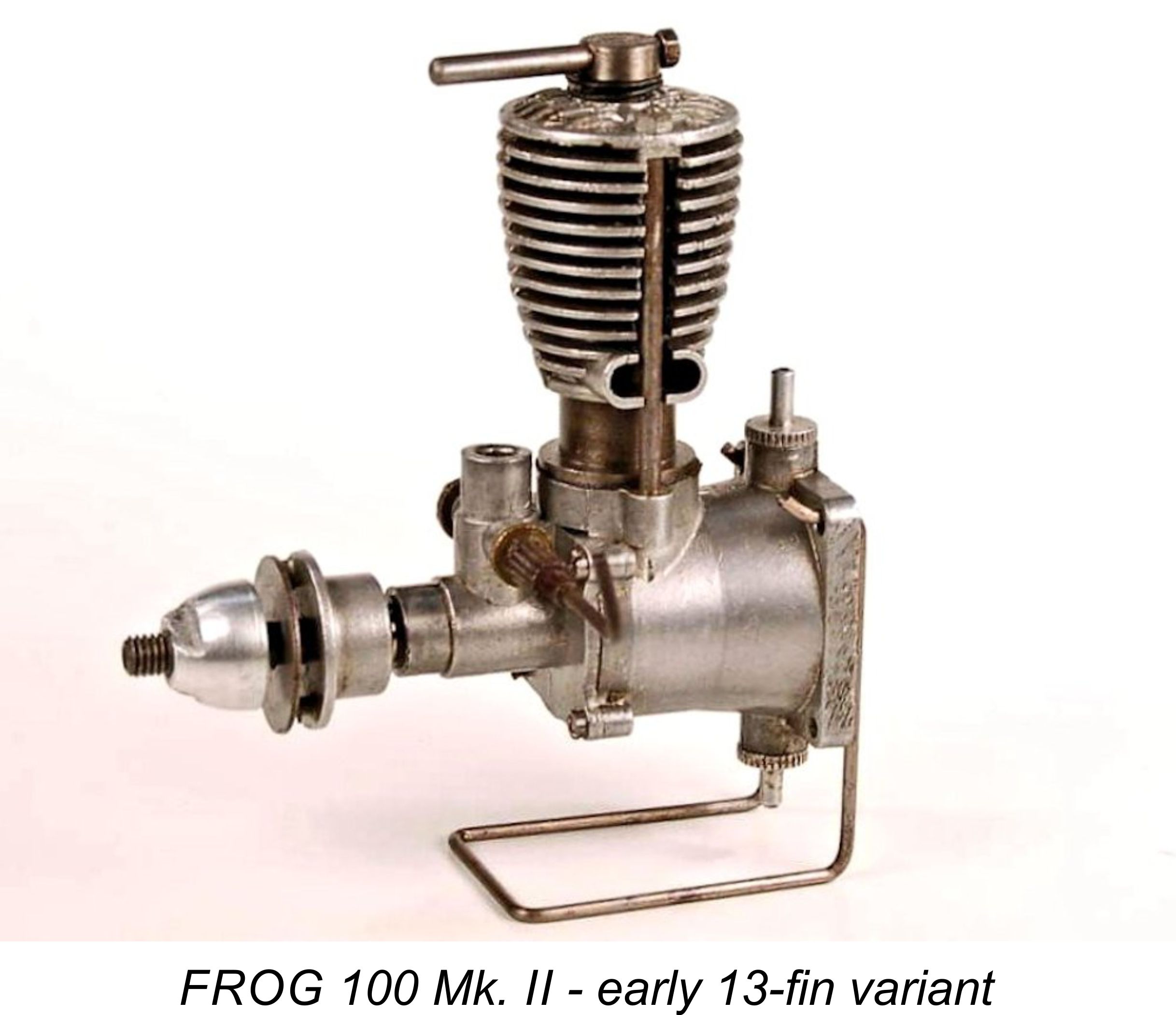 majority of which were to survive in production in one form or another for the next two years. These models began to make their appearance in mid-1948.
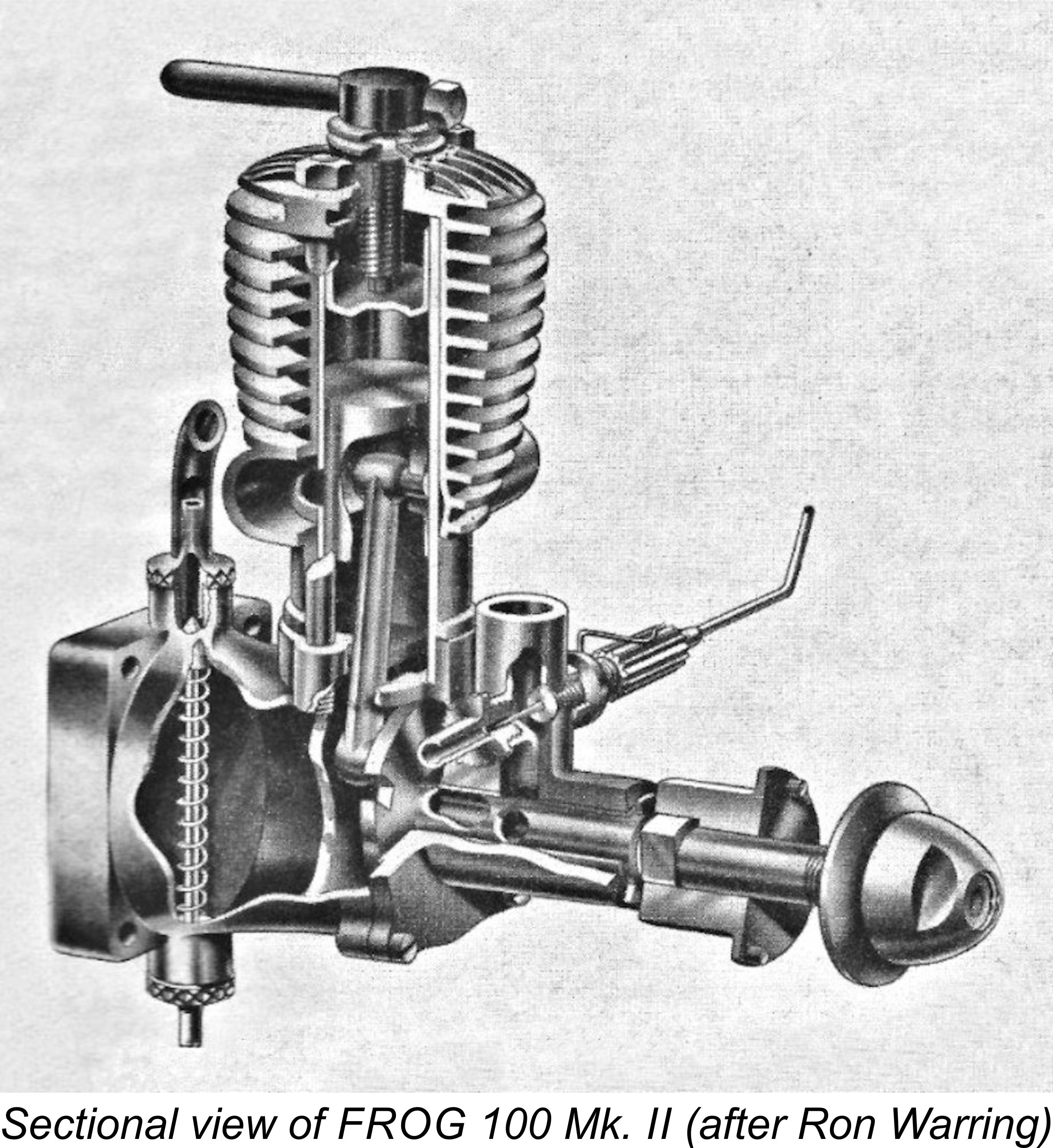 on the later examples to be described below. The casting for the model now being described featured exhaust stacks which had a relatively small area. It also featured 13 cooling fins. The jacket used on the subsequent variant to be described in a later section of this article had larger exhaust stacks and only 11 fins. An important point to note for those concerned with originality, especially given the freedom with which people appear to have swapped jackets over the years!
 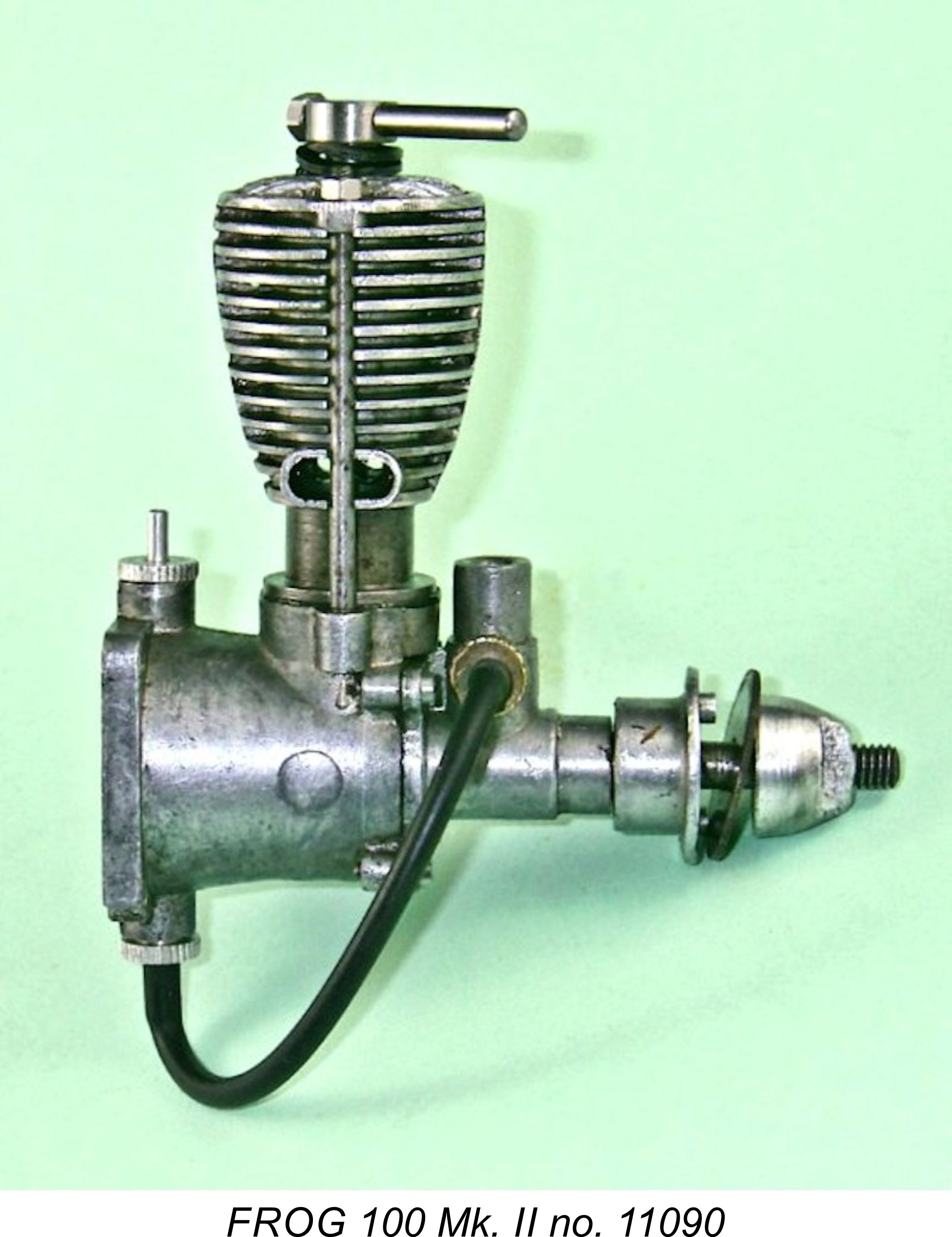 shaft by two flats milled into the shaft just forward of the main journal. This is not an ideal arrangement - the alloy prop driver tends to wear quite rapidly at the flats, resulting in the development of a “wobble” fit which can eventually progress to failure. If this happens, the only fix is to convert the system to the far more dependable split-collar arrangement. Fortunately, this is easily done by anyone having access to a lathe.
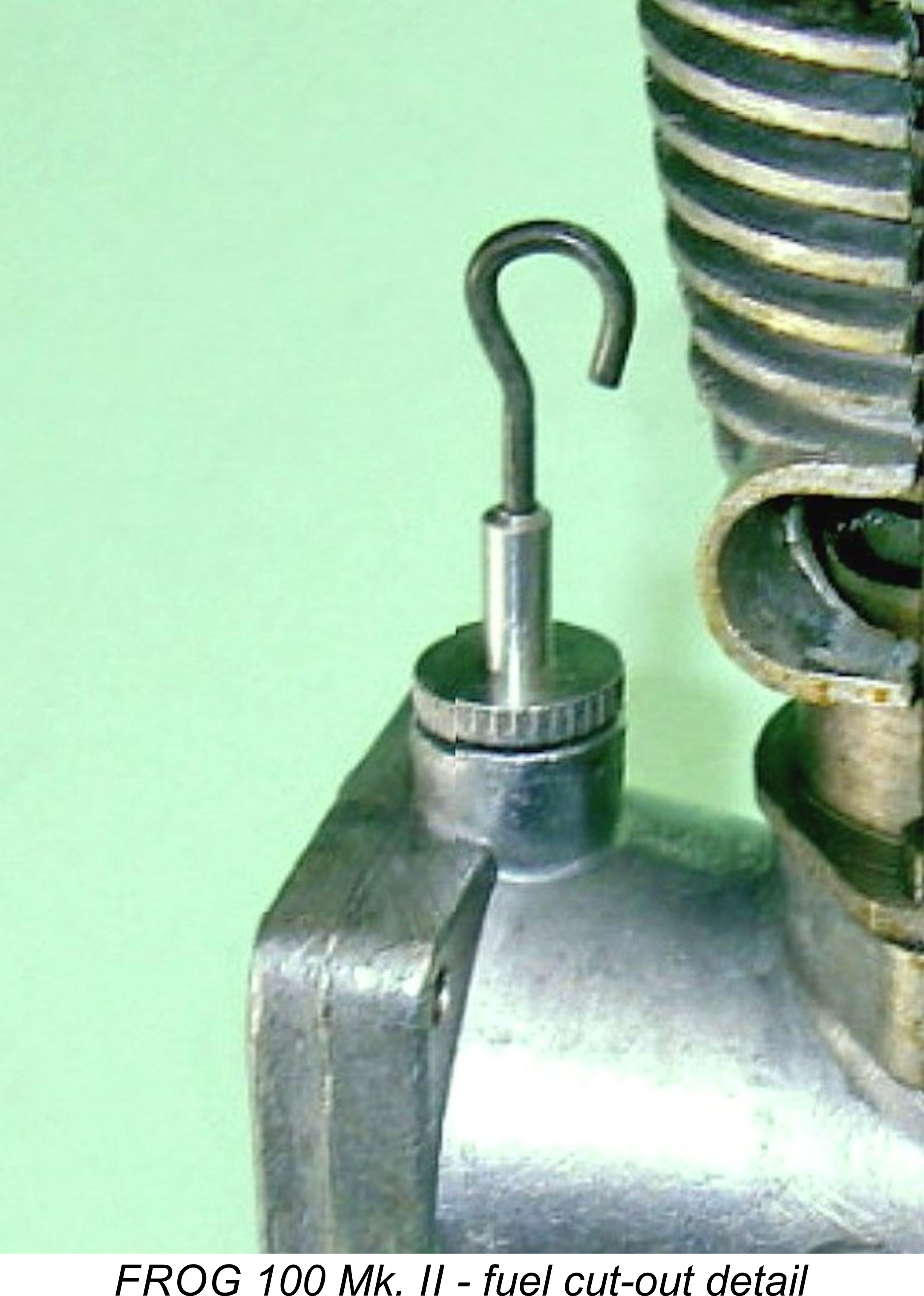 A feature which seems to have been introduced at around this time or possibly a little earlier was a form of fuel cut-out. This consisted of a spring-loaded plunger operated by a wire which passed through the central hole in the uppermost of the two fuel tank spigots. The lower end of this plunger carried a plug which entered the lower spigot from the inside when the plunger was released, thus effectively blocking the fuel supply. This device is clearly visible in a number of the engine images which accompany this article, including the above sectional view.
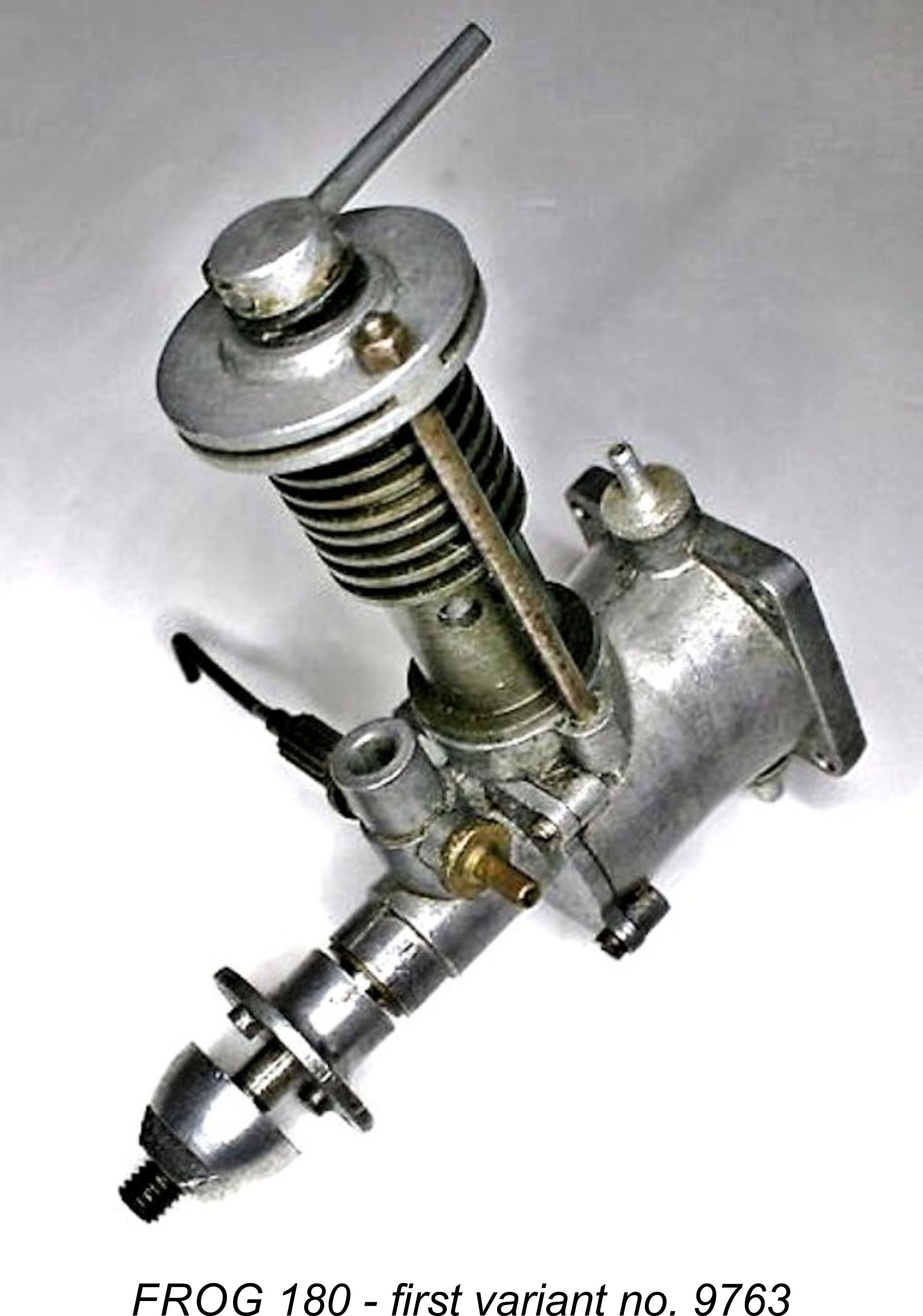 Concurrently with the revisions to the cylinder assembly for the FROG 100, IMA also expanded the range. The first new model to appear was the FROG 180 diesel. Several confirmed survivors attest to the fact that a few examples of this engine were actually constructed along similar lines to the original FROG 100 with a Meehanite cylinder having integral cooling fins, presumably in early 1948. The additional displacement was obtained entirely through an increase in the bore to 12.70 mm for a displacement of 1.77 cc (.108 cuin). In other respects, the original FROG 180 was identical to its contemporary 100 sibling. Serial numbers for this variant appear to have been tacked on to the upper end of the original FROG 100 model in the 9000 range - the sole number which has been confirmed to date for one of these very rare models is 9763.
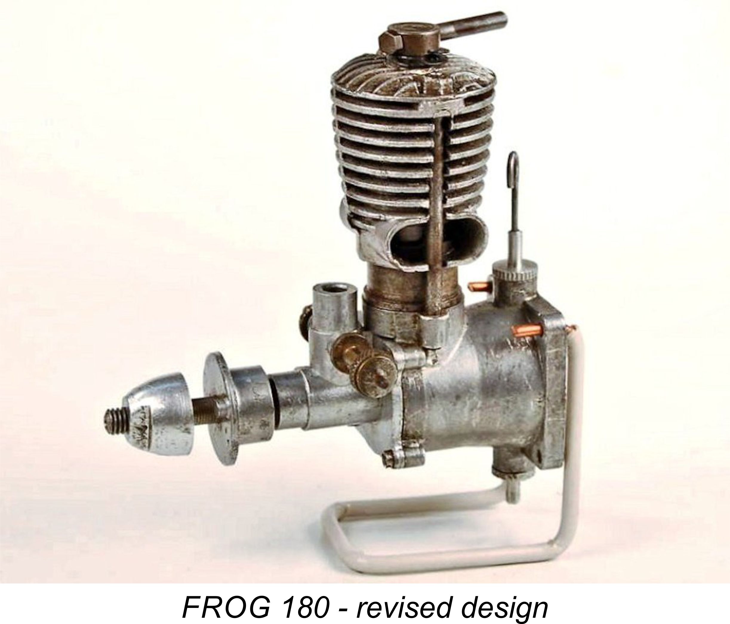 The real genius of this move lay in the fact that since the two models were based upon identical lower castings, their mountings were interchangeable. Thus a 100 owner wanting more power for his model creation could simply buy a 180 and bolt it in! The 107 gm weight of the 180 was very little greater than the comparable figure of 104 gm for the companion 100, and this difference could easily be accommodated by trimming. Moreover, the slight additional weight was more than compensated for by the added power.
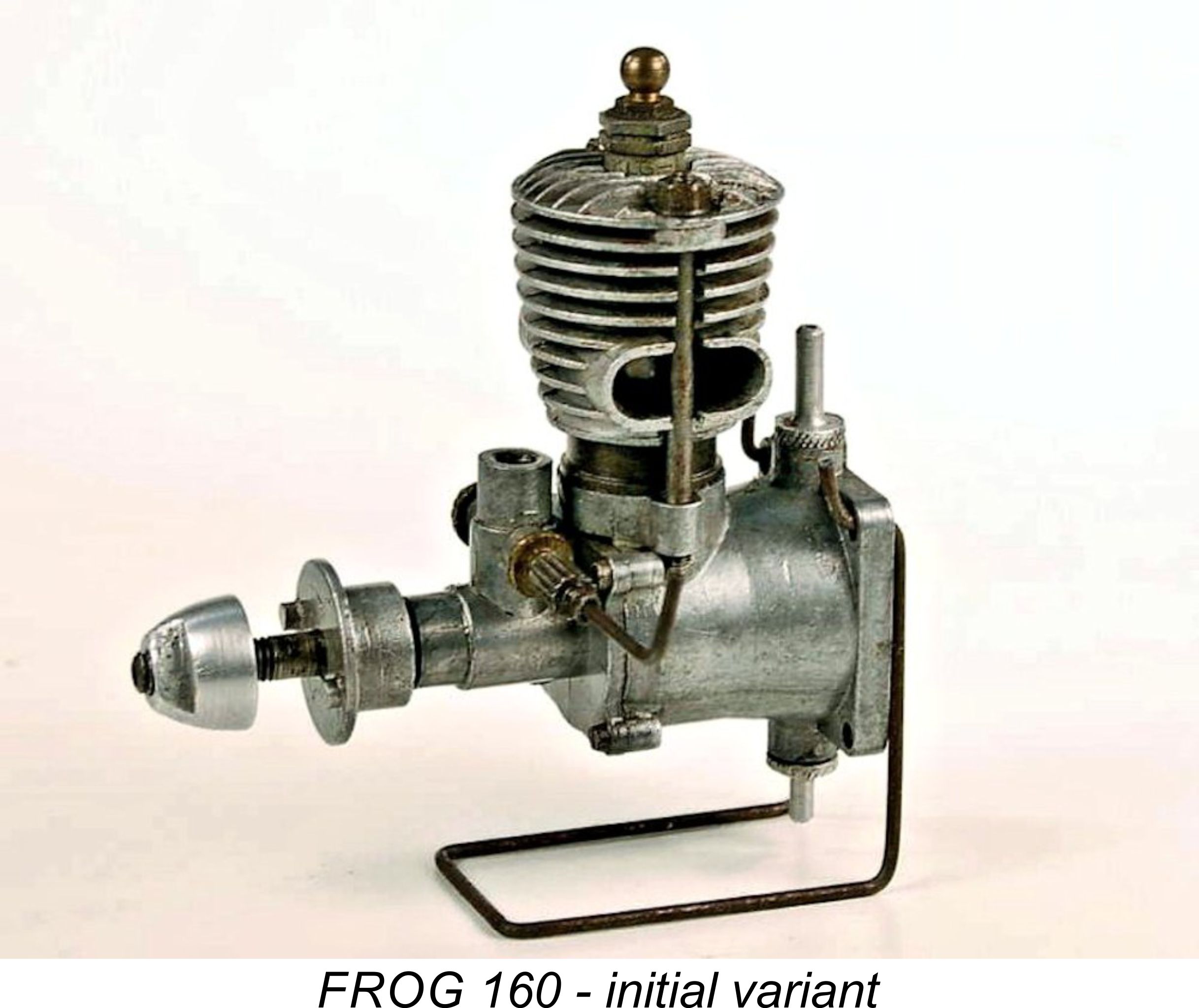 The two revised diesel models described earlier were both featured in advertisements from June 1948 onwards. However, the 175 sparker was by then conspicuous by its absence. It appears from this that plans were already afoot for its replacement, which duly appeared shortly thereafter. This was of course the original variant of the FROG 160 glow-plug model, which was in fact the first small-displacement glow-plug engine to enter series production in Britain,
 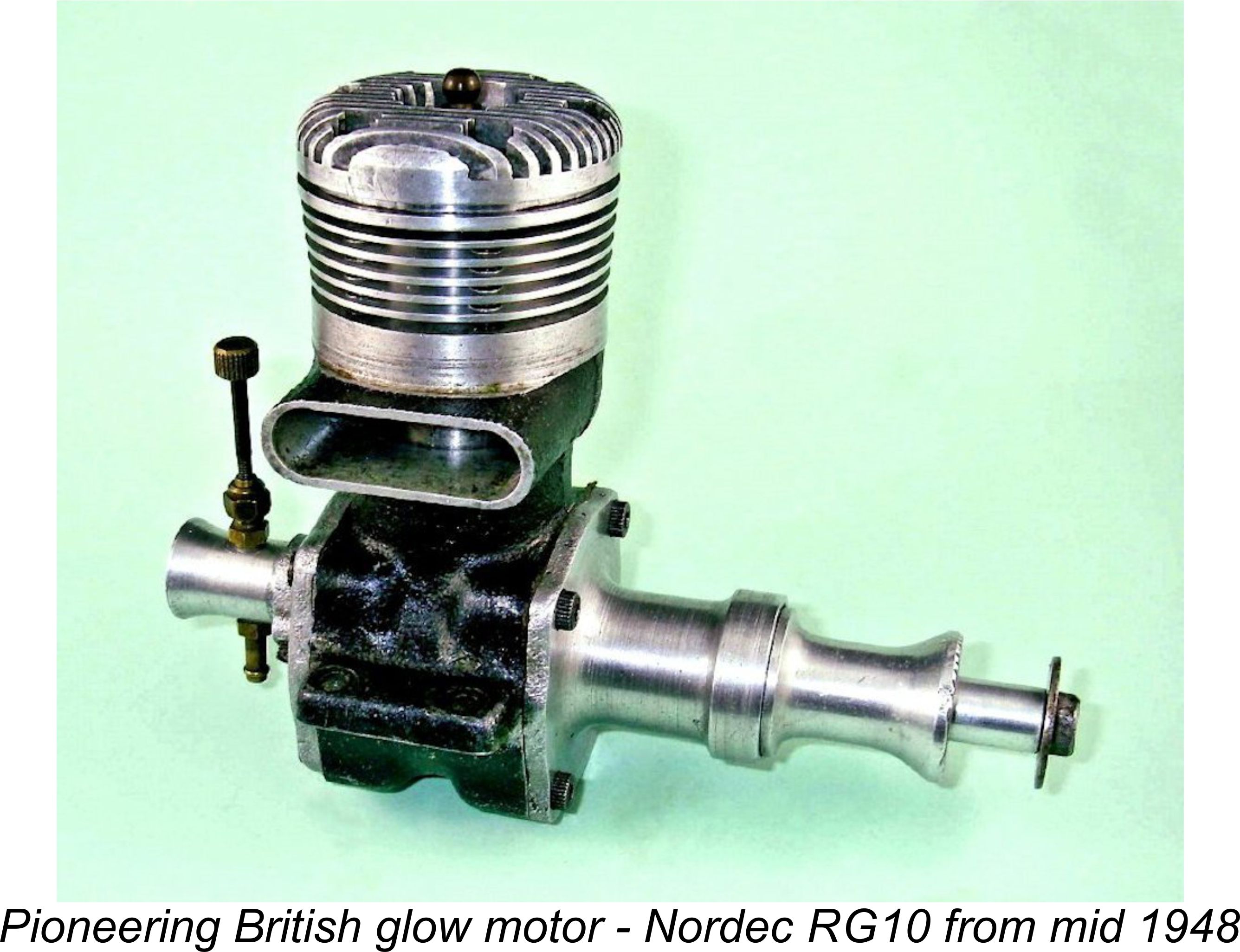 engine introduced in early 1948. They were later to offer a glow-plug conversion kit for their disc-valved 1951 Mk. III replacement, the 2.46 cc E.D. Racer.
 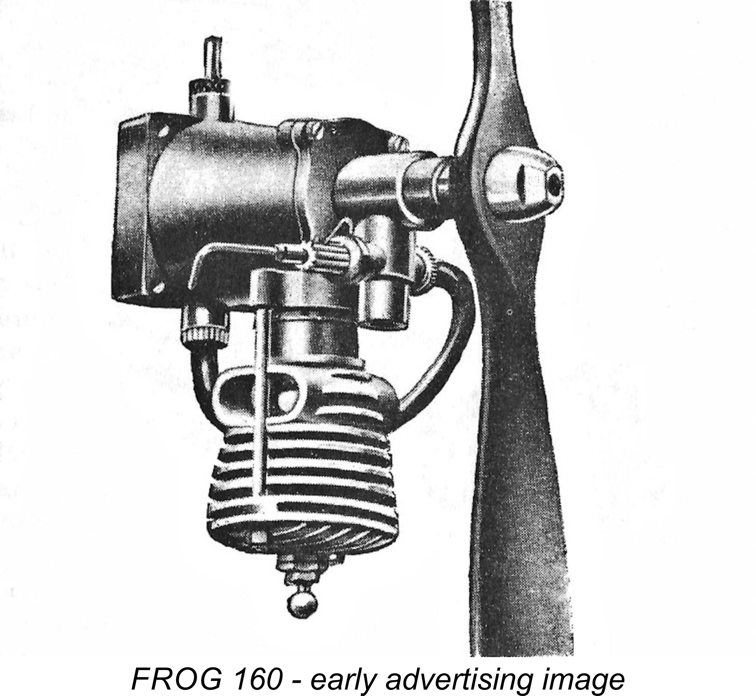 So the next step in the “bicycle spoke” saga was a move towards the replacement of the 175 spark ignition model with the 160 glow-plug version of the basic FROG design. This was in effect a re-configuration of the newly-introduced 180 diesel in glow-plug form. As before, it shared the lower end components of its two contemporary diesel relatives. Hence stroke was unchanged at 13.97 mm. However, the bore was slightly reduced from that of the 175 (and the 180) to 12.32 mm, giving a displacement of 1.66 cc (0.101 cuin).
 rebuild by a collector completing an engine from parts, and vice versa - the odd “160” glow-plug model turns up with a
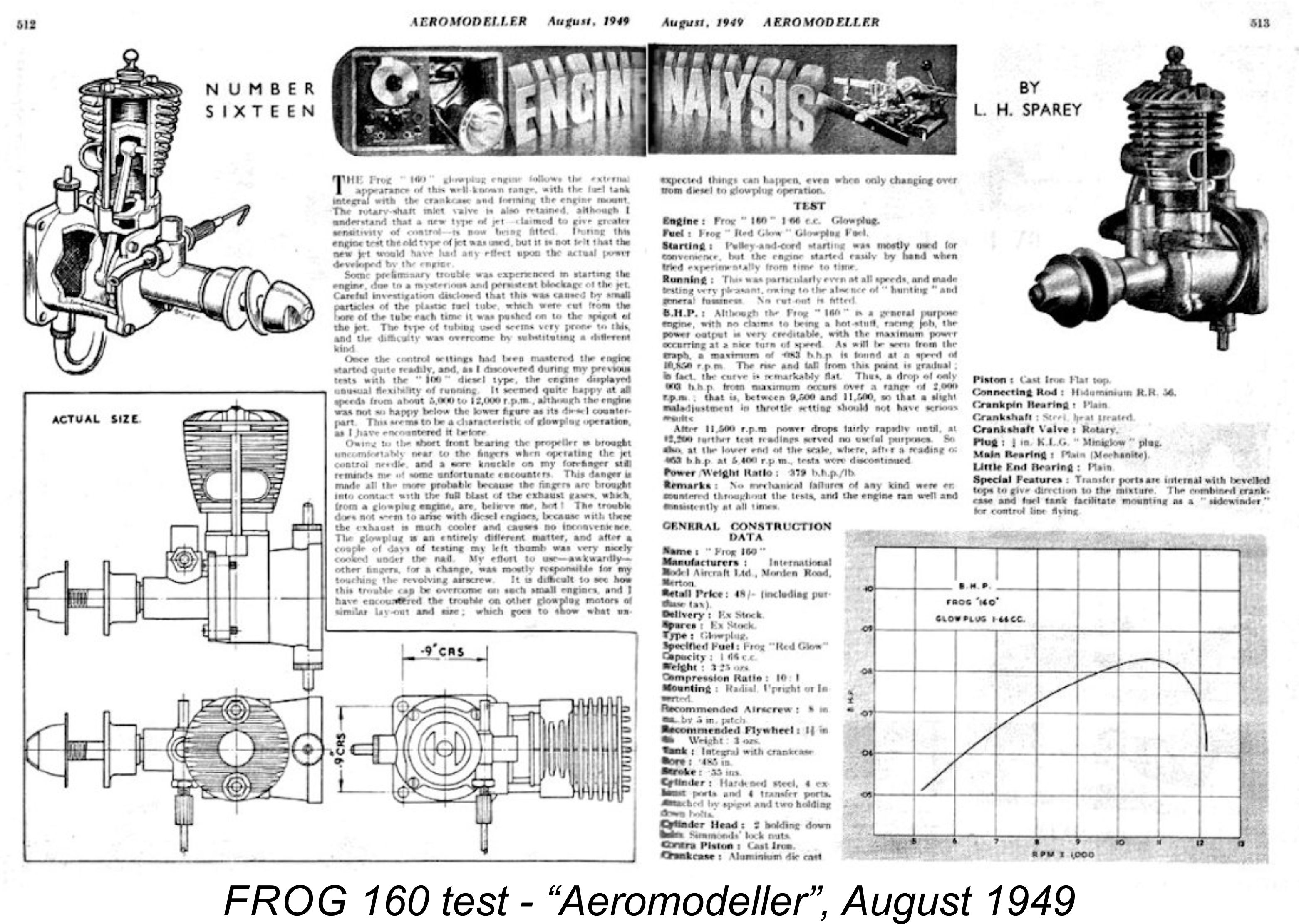


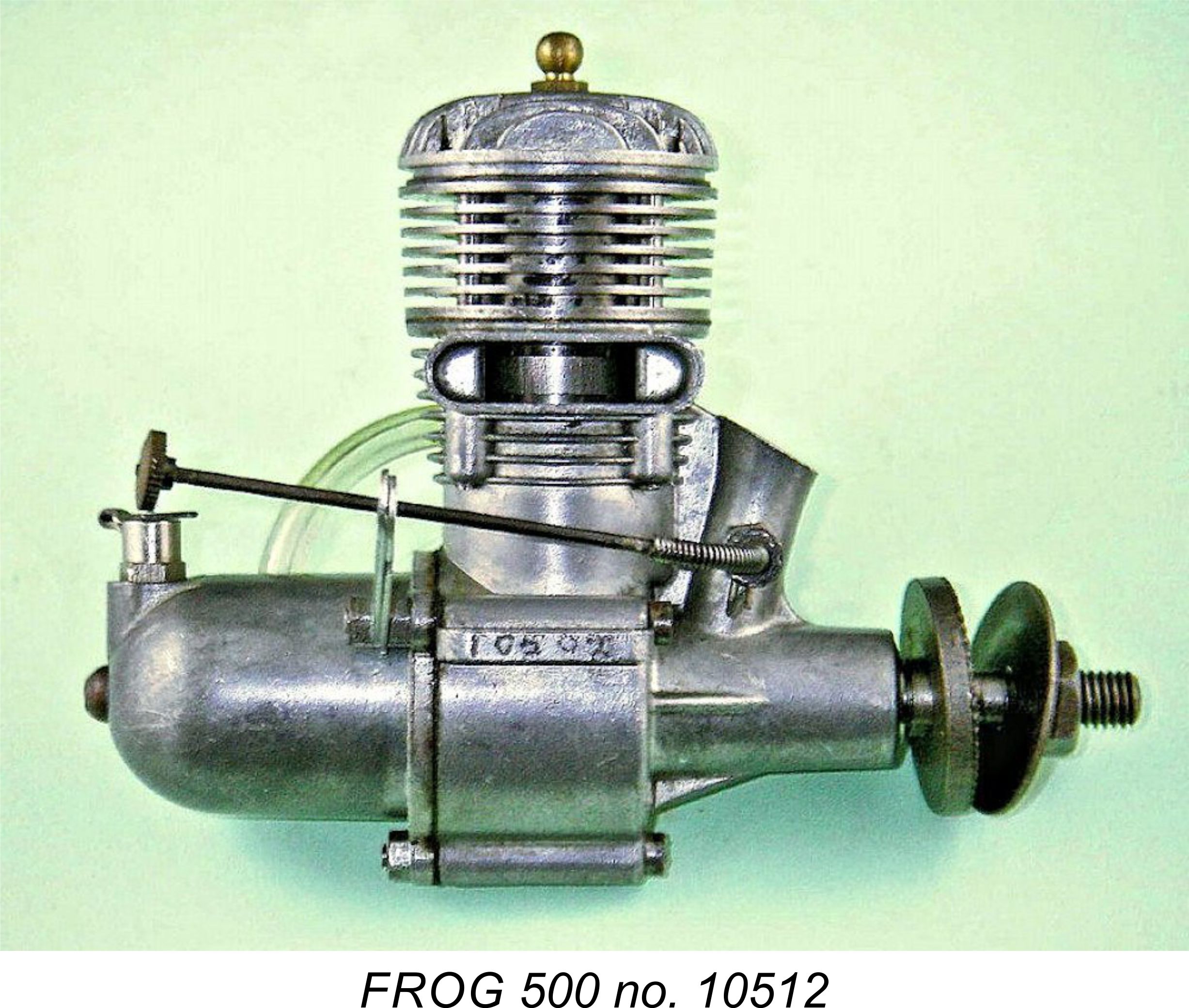
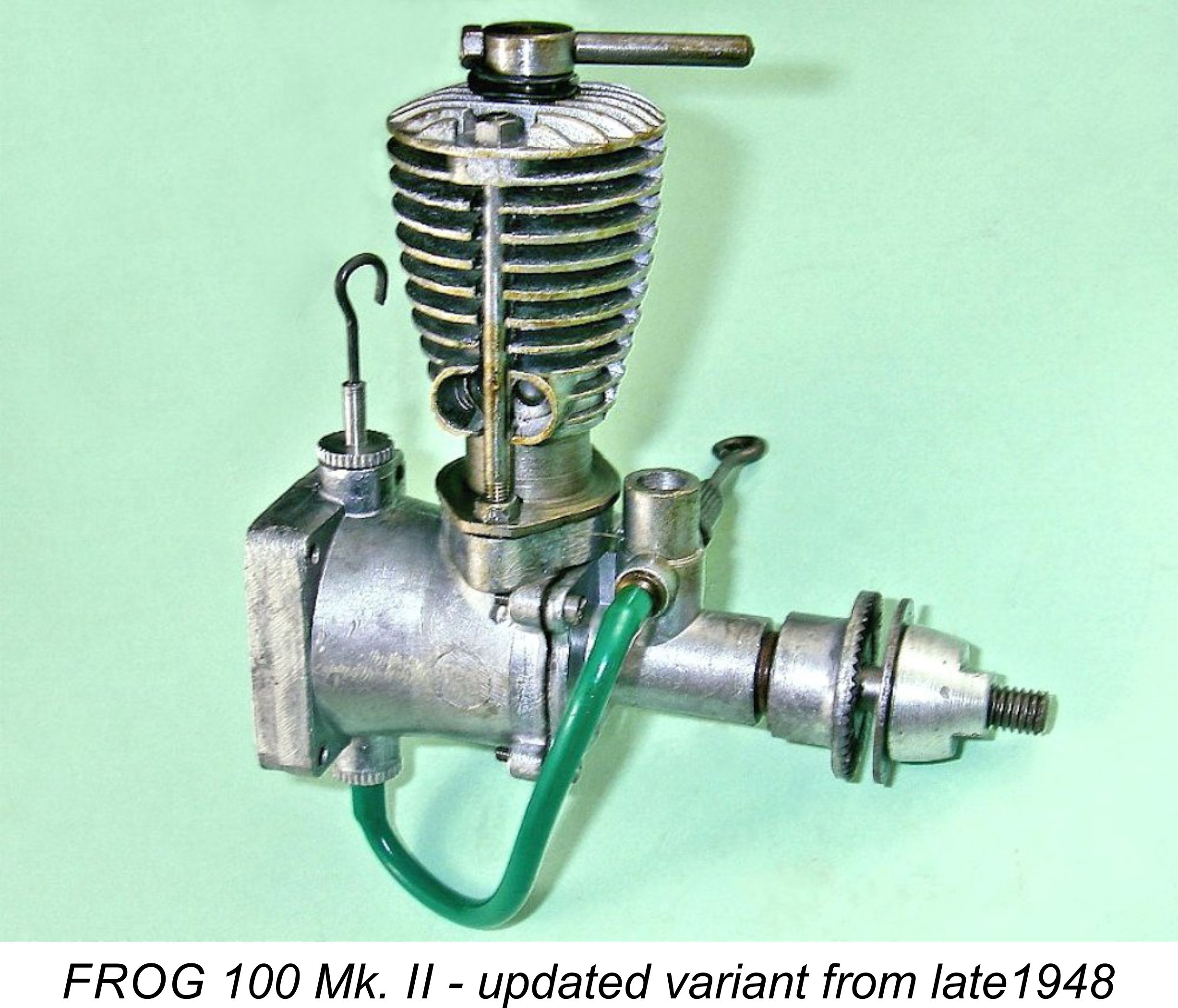 In all of the models described up to this point, the entire cylinder assembly had been held down solely by the two 8 BA nuts on top of the hold-down studs. The maintenance of an adequate head seal on the spark ignition and glow-plug models in particular had resulted in frequent over-tightening of these nuts and consequent stripping of the threads. The additional stresses imposed on the system in the two diesel models with their compression ignition must also have strained the capacity of this hold-down arrangement. Furthermore, the crash resistance of this system was highly questionable. It was clear that the time had come to respond to this unsatisfactory situation by making further structural modifications to the design. Engines featuring such revisions began to appear in late 1948 or perhaps early 1949.
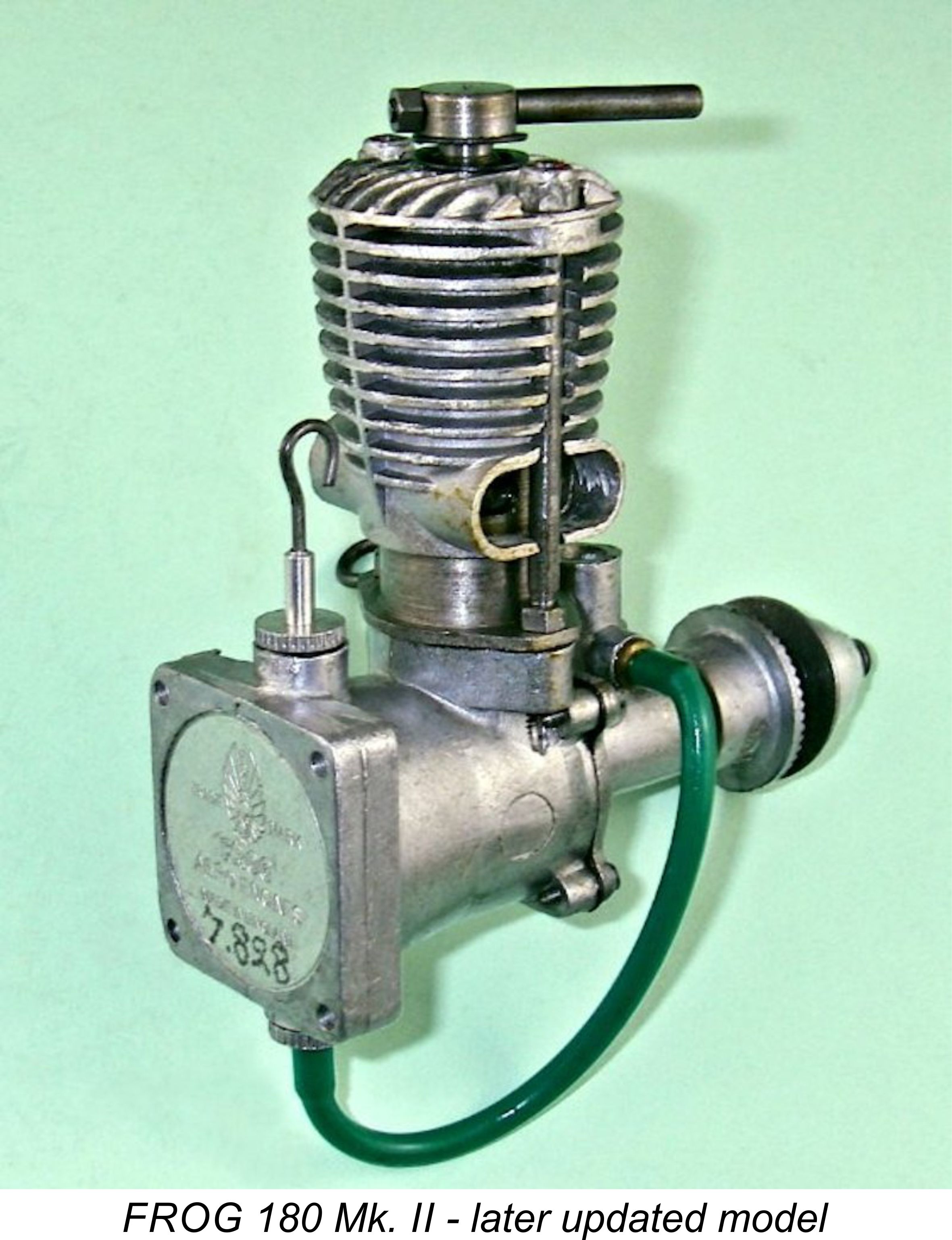 and its contemporaries was retained on all models complete with its twin exhaust stacks. However, the jacket casting for the FROG 100 was revised as mentioned earlier, with the modified component having larger exhaust stacks and only 11 fins in place of the former 13.
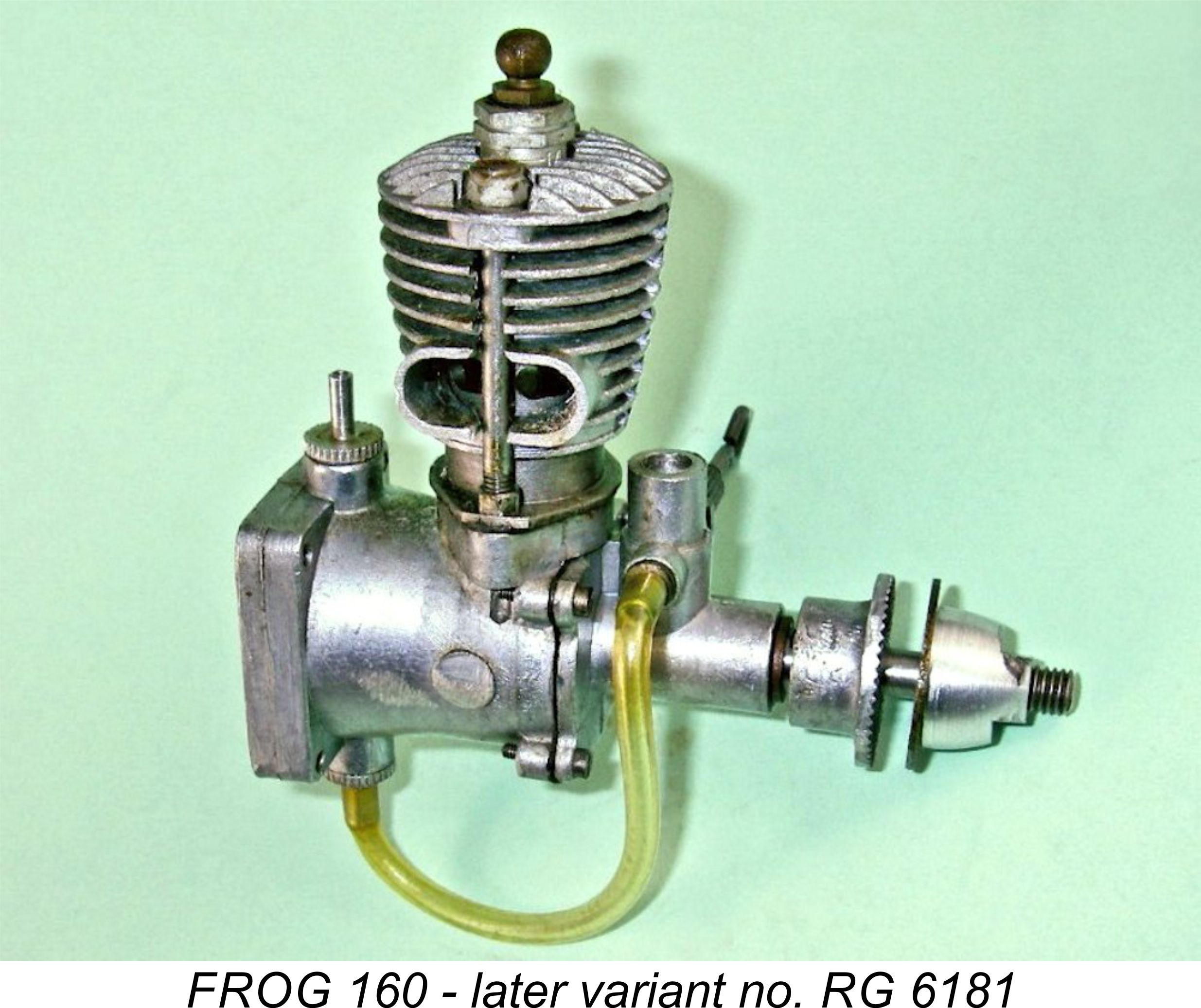 to do this rather than to retain the entire cylinder set-up. This greatly reduced the hold-down stresses in the cylinder walls and the consequent potential for distortion.
 Apart from the relatively squat 160, the revised engines retained the rather “tall” appearance which was even then becoming rather antiquated and “old fashioned”. To a very large extent, this was due to the extremely (and unnecessarily!) long contra pistons employed in the diesel models. Presumably the makers hoped to eliminate leakage past the contra piston and obtain a better “feel” for adjustment by doing this. We now know that this was not necessary - the engines could easily have been “prettied up” somewhat by making them lower (and also lighter).
 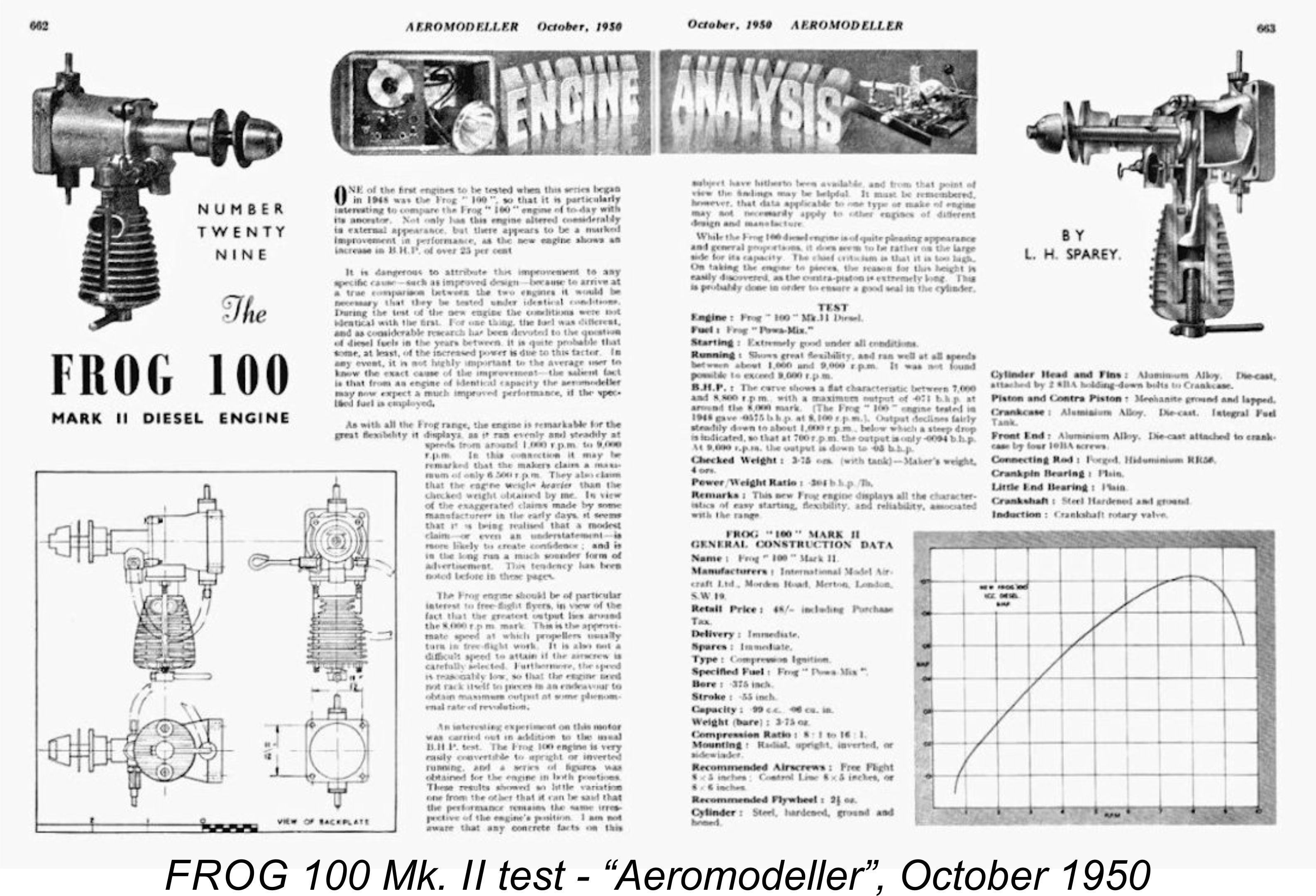 The numbering sequences for the companion 180 and 160 models seem to have been continued without interruption when the revised versions were introduced. The range of presently-reported numbers for the final variant of the 180 diesel goes from 6485 up to 8321, implying the production of perhaps 3,000 examples. The range for the final variant of the 160 glow model extends from RG 5032 up to a present high of RG 6585. The very substantial gap in the sequence between the first and second variants of this model makes it impossible to come up with a firm production estimate. We would probably not be too far wrong in hazarding a guess that as many as 3,000 examples may have been manufactured in total.
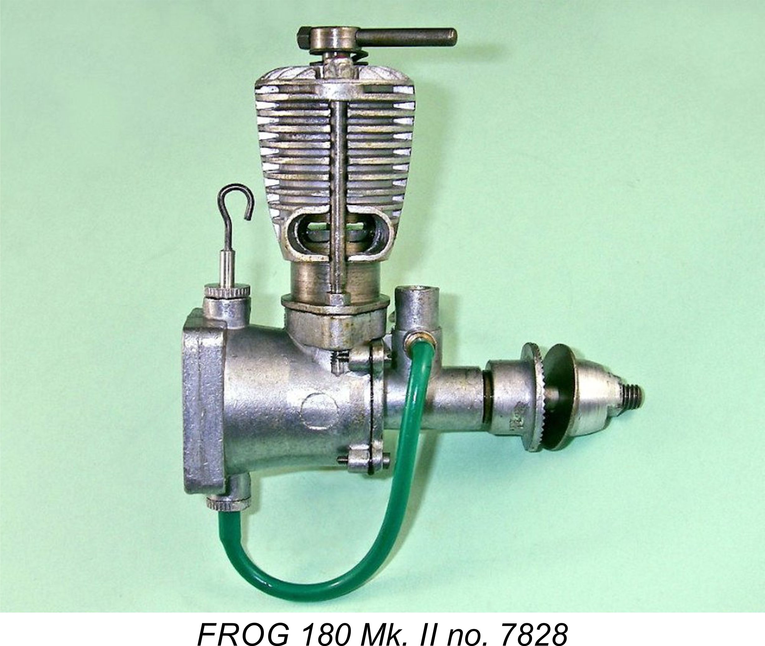 original version, because the peaking speeds were essentially the same.
 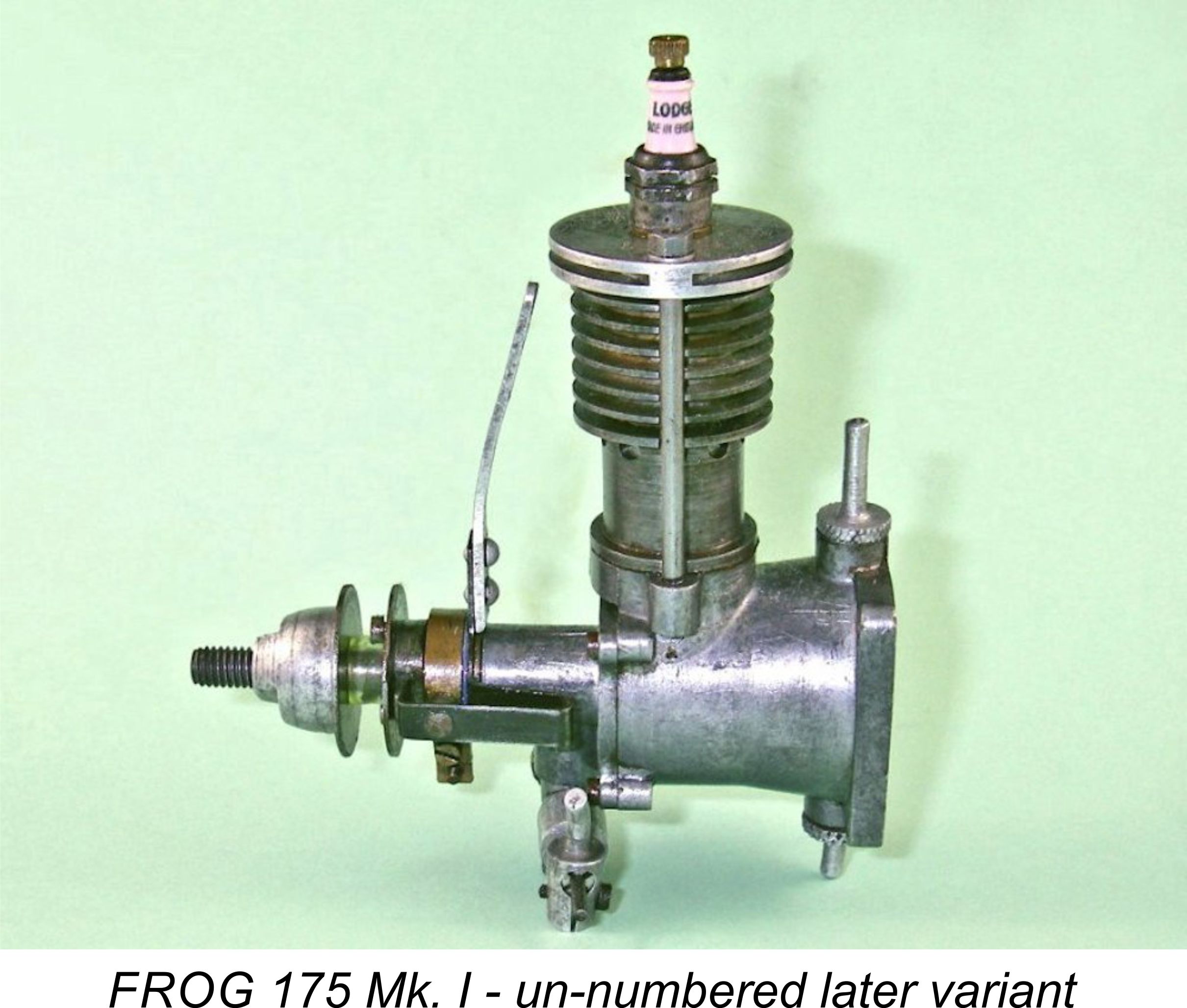 175 spark ignition model since that model was in production for well over a year by the time the FROG 100 appeared, only beginning to carry serial numbers at that point in time.
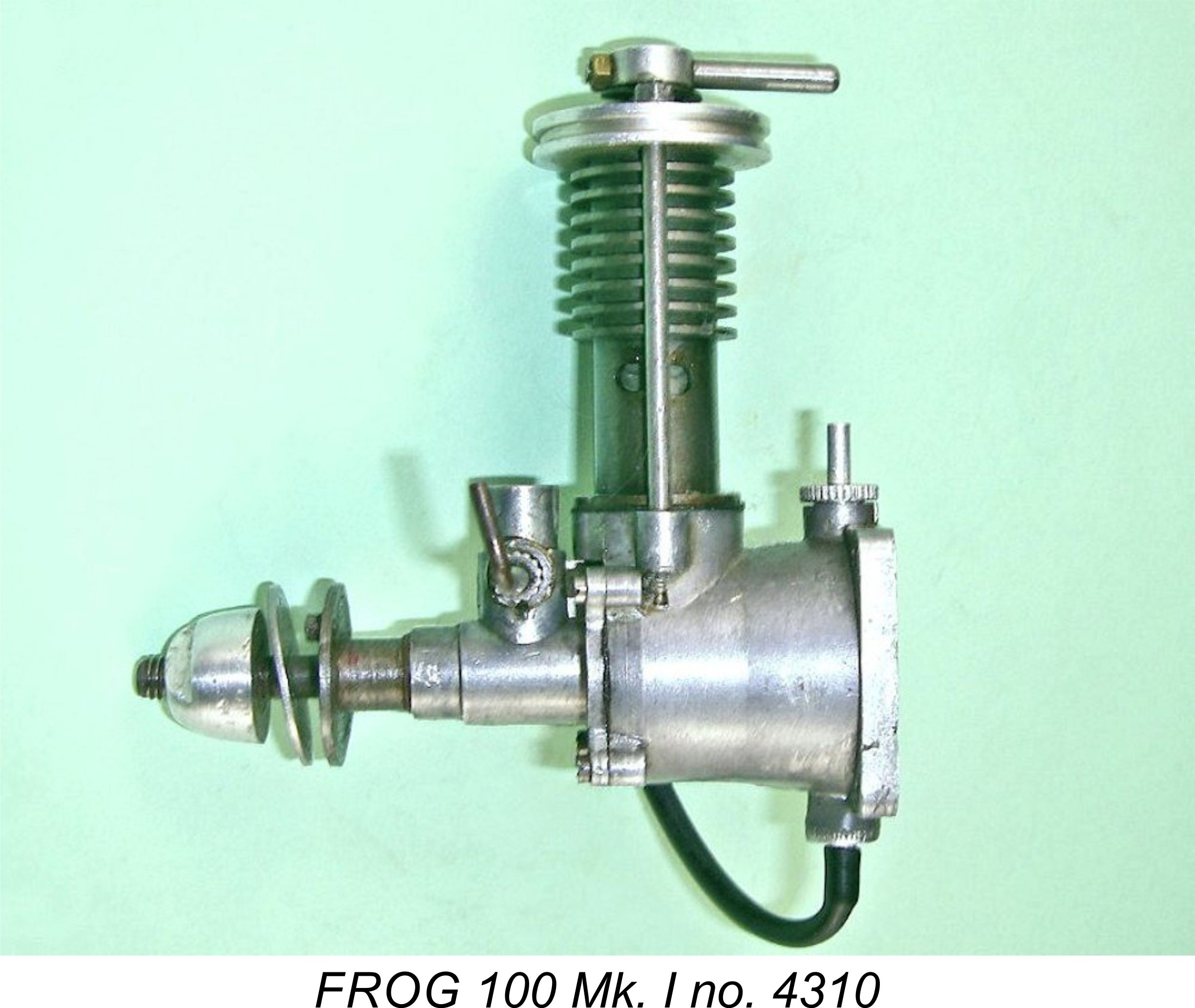 When it comes to the FROG 100 diesel, we are on firmer ground. Assuming that the numbering sequence started at engine number 1001, as discussed earlier, we have hard evidence in the form of reported serial numbers for the manufacture of at least 7500 and possibly as many as 8,000 examples of the original version over an approximately one-year period. This implies an average production rate of 650 or so examples per month over and above the ongoing production of the 175 sparker. Production figures for the 175 were almost certainly considerably less than those for the 100 during this period. However, IMA's total monthly production capacity may well have been approaching the 1000 unit per month figure at this stage.
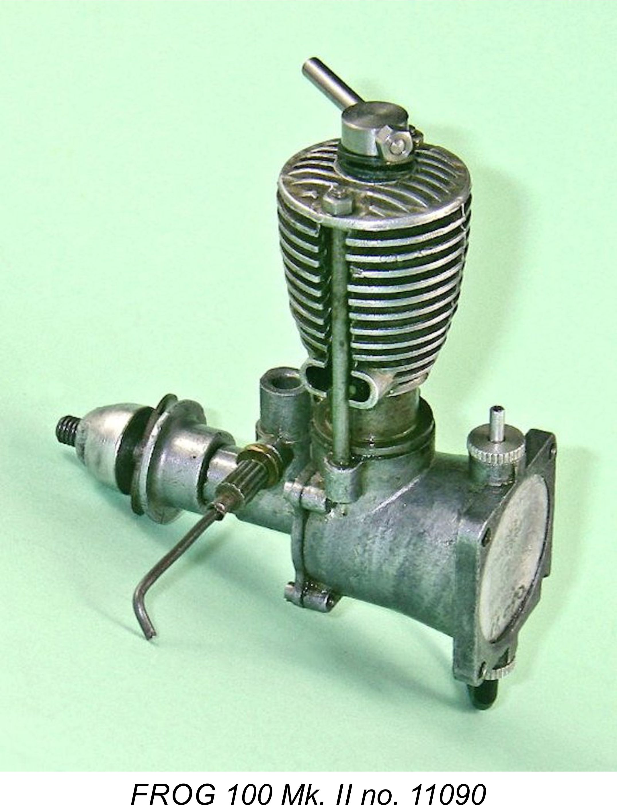 serial number evidence for the manufacture of at least 5,000 examples of that variant - an average of over 750 engines monthly, and this at a time when the companion 160 and 180 models were also in full production. Clearly, IMA had significantly increased their production capacity by this time.
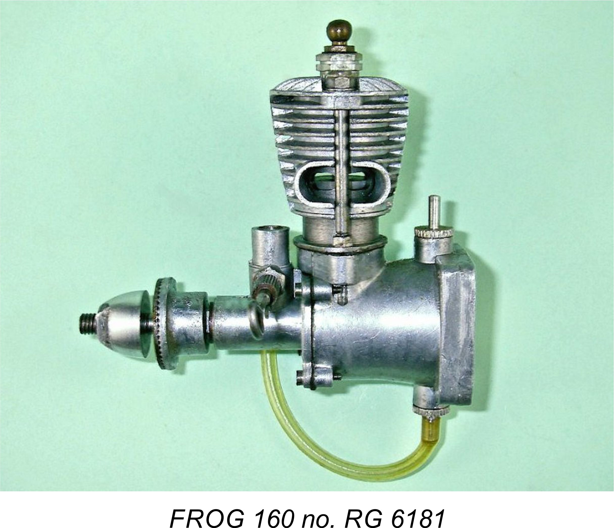 For me, the most surprising finding to emerge from the above analysis is the fact that the most prolific model of the FROG 100 diesel appears to have been the original Mk. I version of mid 1947! This is a highly unexpected finding based on apparent survival rates - that variant has widely been regarded as one of the rarer models. The seemingly low proportion of survivors in good condition relative to the number made is probably explained by the engine’s inherent fragility - a lot of them likely became damaged in service through crashes, abuse, etc., and were discarded. The other factor in play here may well have been the cast-iron piston/cylinder combination, which probably caused the engines to wear out rather quickly. Given their relatively low monetary value, many of these worn-out examples may well have been discarded rather than being repaired.
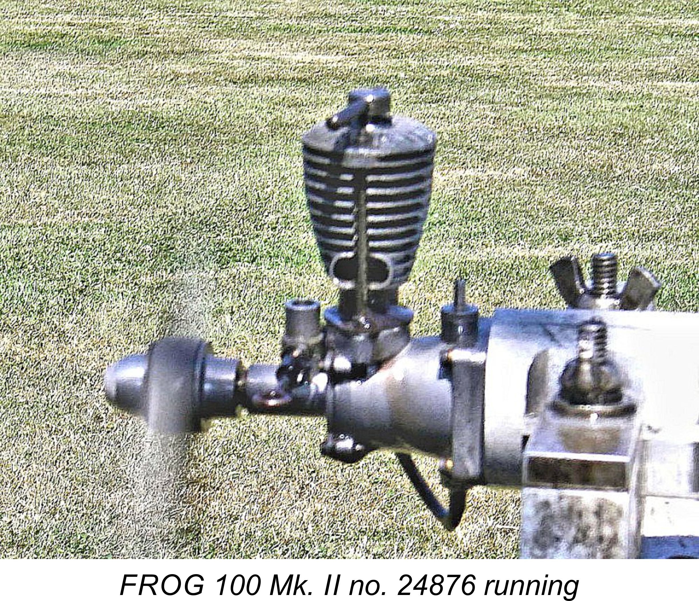 Once going, the engines run very consistently indeed with excellent response to the controls, being extremely easy to set as a result. The needles are a bit coarse in action, but a good setting is readily obtained regardless. The 180 is far more powerful than either the 100 or the 160 – if you built a model for either of those two that proved to be underpowered, this was a complete answer!! The 160 glow-plug model starts and runs equally well, albeit significantly down on torque compared to the 180.
 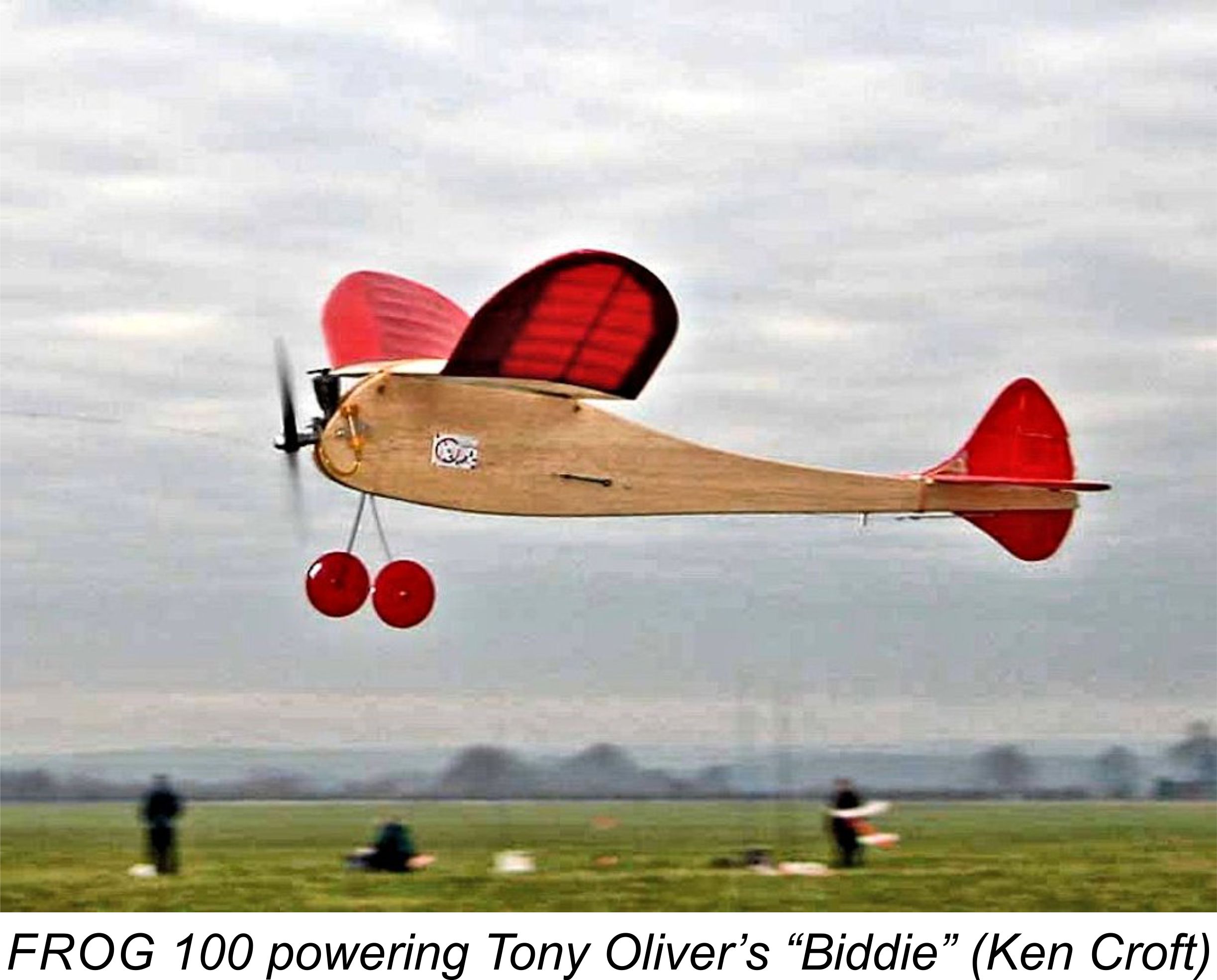 they have to be sufficiently tight to maintain a good seal between the underside of the jacket and the top of the cylinder. Even so, tight enough to seal when running and no more is the goal at which to aim here. If you have a spark ignition or glow-plug model with a good head seal, my advice is to be very thankful and leave well alone!
 Accordingly, if you want to give one of these interesting old engines a try, go ahead and do so - you should be able to find one with little trouble. Just check that all threads are intact before buying. The most common problems arise in connection with those ridiculously tiny 10 BA front cover hold-down threads. They will take little more than finger-tightening before stripping, and many did in fact strip. You will run into the odd stripped example that has been cosmetically repaired with epoxy - there are those who may take advantage of an unsuspecting buyer this way, so be warned! The lugs can easily be re-tapped 8 BA if necessary, giving a far superior level of engineering integrity.
 | |