 In this article, I’ll present what I believe to be the first-ever full published review and test of one of the pioneering large British diesel engines – the 4.4 cc Kemp K4 from early 1947. This engine was manufactured in relatively small numbers before being supplanted by a series of new more broadly marketable designs from the same manufacturer and its successor company. As a result, the K4 is rarely encountered today, being in fact among the almost forgotten products of the British model engine manufacturing industry.
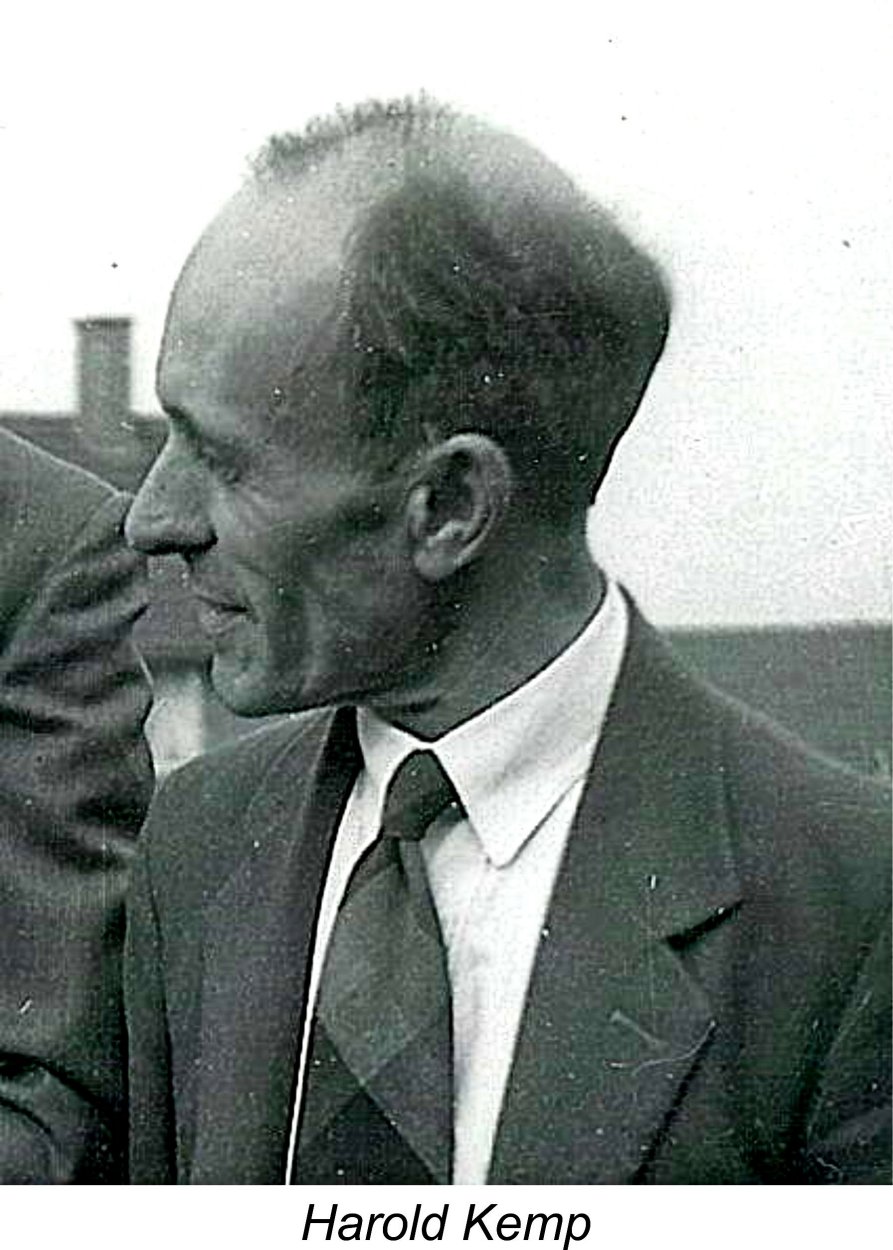 The Kemp Engines company which introduced the K4 diesel was founded in 1946 by Harold Kemp. During the preceding war years, Kemp had worked in the full-size aircraft industry for
 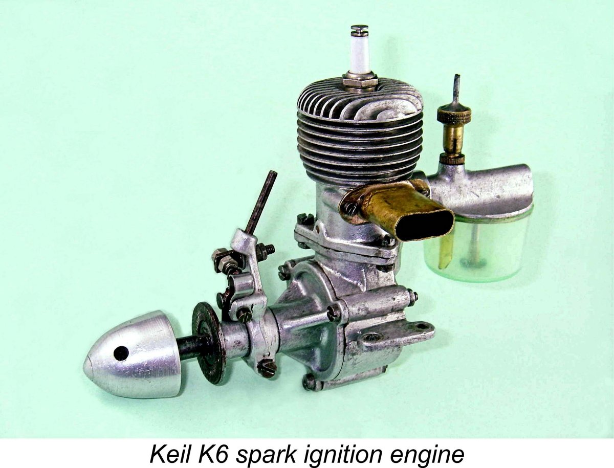 The one straw in the wind is the long-standing oral association of Kemp's name with the beautiful but fragile 6.38 cc
 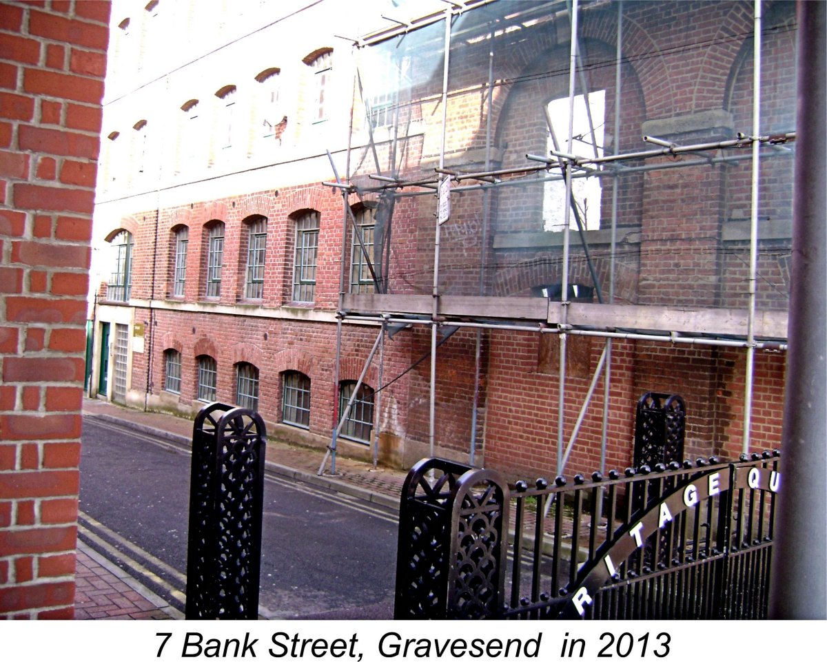 this in assembling the necessary production equipment. Much of this machinery was doubtless well-used and rather "tired", but the price was right. Moreover, a combination of realistic tolerances, skilled operation and careful individual fitting could do much to overcome any deficiencies.
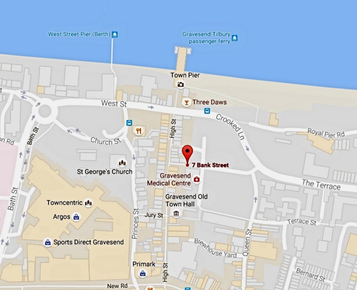 at Kemp Engines was Les Duffy, a former colleague of Kemp's at Short Brothers who was still working full-time during the day as an apprentice at the downsized but still operational Short Brothers plant in nearby Rochester.
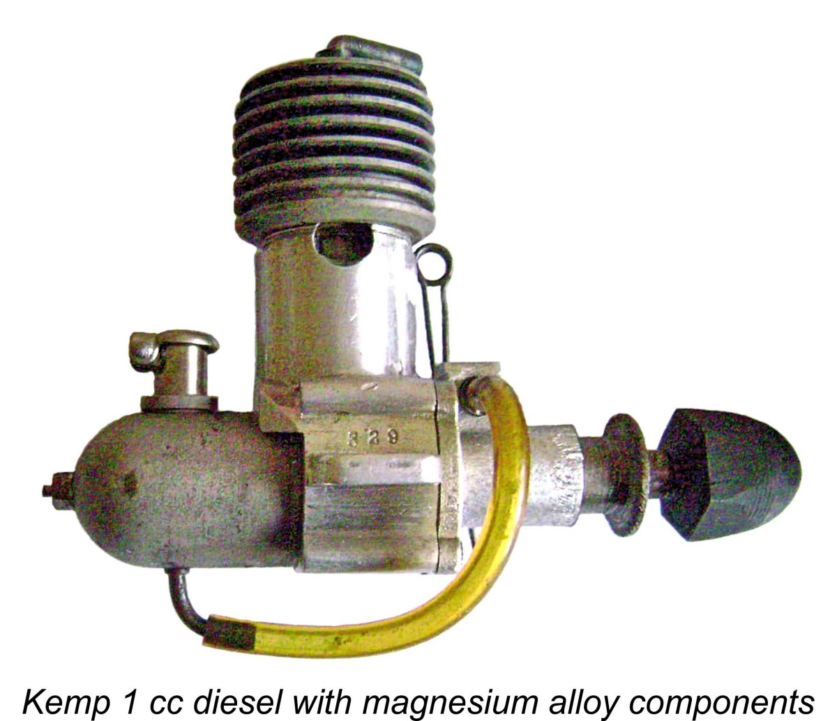 neighbors! Those engines that passed their test were packed into plain brown cardboard boxes ready for dispatch, while the failures were set aside to have their faults rectified. Seemingly, Kemp had a first-rate hands-on quality control program—others might have done well to copy.
The engines could also be bought directly from the makers either by mail order or in person over the counter from the workshop at 7 Bank Street. It would have been well worth taking advantage of the latter option since one would then be served in person by Harold Kemp himself!

|
|
The Kemp K4 – Harold Kemp’s First Model Diesel
A number of my earlier articles on the various designs manufactured by Kemp Engines and its successor company, the K Model Engineering Co. Ltd., both of Gravesend in Kent, may be found both here and on the late Ron Chernich’s now-frozen but still fascinating “Model Engine News” (MEN) website. You can read articles on the 0.2 cc Kemp (and later K) Hawk; the various 1 cc models made by the two companies; the K Vulture 5 cc diesel which supplanted the K4; and the series of 2 cc K models. You may also read the Harold Kemp Tribute Page in which the life of Harold Kemp is summarized by his daughter, Mrs. Jean Hards-Nicholls. There’s also an article by Ron himself on our main subject, the Kemp K4 diesel. However, this did not include a full evaluation and test of the engine. The present article is intended to make good this deficiency. It was also high time that a direct reference to the work of Harold Kemp appeared on this website! I'm immensely grateful to my friend and colleague Miles Patience of England for the considerable help which he provided in connection with this project. Couldn't have done it without you, mate! In addition, I’ve drawn heavily upon my own earlier work as well as that of my mate Ron. Some readers may already be sufficiently familiar with that earlier material that they may choose to jump straight to the description and test report which complete the present text. Feel free to do so! For the convenience of others, I’ll begin the present article by summarizing what is known about the company which produced the K4. Kemp Engines – a Summary
The Short company had established a satellite factory in Belfast, Northern Ireland, in 1936. Following the conclusion of WW2 and the consequent termination of Government defence contracts, plans were set in motion to relocate the entire operation to Belfast. This left Harold Kemp, along with many others, facing some difficult choices. Even assuming that the option of remaining with Short Brothers was open to Kemp, doing so would have required him to relocate to Belfast in 1947 along with the company. If he did not wish to relocate or if he was in any event made redundant, a second option would have been to seek employment in the engineering field with another English firm. This of course would have placed him in competition with large numbers of similarly redundant and perhaps equally qualified individuals. As matters transpired, Kemp took neither of these steps—instead, he elected to remain in Kent, moving to nearby Gravesend and starting his own specialty precision engineering business there. His chosen field was the manufacture of model aero engines, and the original name of the company which he founded was Kemp Engines. A prior involvement with model aircraft or at least an interest in model engineering are implied here, but unfortunately we know nothing definite about any previous association which Harold Kemp may have had with either field.
Although the styles of both its design and construction differ markedly from those of Harold Kemp’s later designs, it remains a completely unsubstantiated possibility that Harold Kemp may indeed have had some involvement with the development and production of the K6. It's entirely possible that he might have worked for Short Brother's co-located subsidiary Pobjoy Airmotors, who developed and manufactured small petrol engines for such applications as reduced-scale prototype aircraft and airborne generators, working closely with Short Brothers in doing so. A statement which appeared in the June 1946 issue of "Model Aircraft" in relation to the Keil K6 referred to the involvement of wartime small-engine designers in the development of the K6. This could well refer to members of the engineering staff at Pobjoy, who certainly had the appropriate expertise. Moreover, Harold Kemp could undoubtedly have been one of those individuals. If anyone knows more, let's hear from you! It's readily apparent that Kemp must have had some rational basis for believing that a viable business could be based upon the manufacture of model engines. It seems safe to assume in addition that he must have begun with some well-developed ideas with respect to model engine design. A measure of practical experience with model engines either as a user or a designer (or both) would certainly best account for these factors. In particular, an earlier involvement with the Keil K6 project would undoubtedly have provided a good basis for Kemp to gain such experience. Once he had decided to engage in the model trade as an engine designer and manufacturer, Kemp did so with energy and enthusiasm coupled with a considerable measure of obvious talent. At the conclusion of the war, significant quantities of machine tooling which had been used in wartime production became available for sale at competitive prices as being surplus to peacetime requirements. We may safely assume that Kemp (like many others) took full advantage of Premises were established at 7 Bank Street in Gravesend, Kent. To be near his work, Kemp took up residence at 3 Bank Street almost right next door. Fortuitously, another engineering firm had premises opposite the Kemp workshop, providing Kemp with periodic opportunities to exchange materials and other bits and pieces with his neighbors. In staking his future upon this entrepreneurial participation in the post-war model industry, Kemp was far from being alone. He was just one among a number of technically talented individuals who found themselves in need of civilian employment after the war and chose the model engine manufacturing field as the solution to their employment challenges. To take one other well-known example, the soon-to-be famous E.D. company was also founded in 1946 by a cooperative group of redundant former employees of Nash & Thompson of Kingston upon Thames. Although operated independently, Nash & Thompson was an element of the Parnall Aircraft Company of Yate, Gloucestershire. Both E.D. and Kemp Engines thus had a very similar genesis. However, the Kemp operation was established on a far smaller and more personal scale than that of its Kingston-on-Thames competitors. Harold Kemp was very much a "hands-on" businessman, being personally involved in all aspects of his company's operations. Apart from handling the sales and other business matters, he carried out all of the engineering design and also worked in the machine shop alongside the other employees. In addition to Kemp himself, the operation initially employed only three other men - two full-time and one part-time. A far cry from E.D., who started with a full-time workforce of some 50 individuals and went on from there! The part-timer Les supplemented his income and helped his mate Harry by working at Bank Street in the evenings for a couple of hours, turning, milling and honing engine parts before returning to his home in Tilbury, Essex on the opposite bank of the River Thames. This was made possible by the existence of a ferry which ran across the River Thames from the Gravesend Town Pier direct to Tilbury. This ferry service survived until March 31st, 2024 when the operating company's contract expired, ending 170 years of service. As the attached location map shows, 7 Bank Street was only a very short walk from the Town Pier. Even so, Les was certainly a long-distance commuter by the standards of the day! Speaking many years later to Harold Kemp's daughter Jean, Les retained some very clear recollections of the workshop at 7 Bank Street. His evocative eyewitness description constitutes an invaluable insight into the way that small-scale "cottage industry" engine manufacturing operations like this typically worked. It appears that the premises had originally been a residence and had been converted to a workshop at some time prior to Kemp taking up occupancy, most likely in connection with the war effort. This kind of adapted accommodation was probably entirely typical of such small-scale engineering operations - large purpose-built factories like those of International Model Aircraft (IMA) and E.D. were undoubtedly the exceptions rather than the rule in Britain at the time in question. Les recalled that as one approached the premises one would usually find a motorcycle leaning against the outside wall. As one entered the building, there were large doors on the left which opened into the main workshop. A large window looked into another room on the right. The main workshop on the left housed a large capstan lathe and an extremely oily work bench, also used for counter sales which were usually handled personally by Harold Kemp. The downstairs front room on the right with the large window accommodated additional lathes and other machinery. These two downstairs rooms were probably the living room and dining room of the original residence! One of the upstairs rooms (likely a former bedroom) was used for assembling the engines, after which each and every one was test-run on the premises. Try that today - Harold must have been popular with the Some of the engine castings, including those for the K4 as well as certain components of a smaller 1 cc companion which soon joined it in the range, were formed in magnesium alloy. These castings were produced at a nearby foundry in Gravesend. They were delivered loose in hessian sacks and had to be individually checked for defects before machining and assembly. The castings were emptied out onto the workbench, examined and sorted. It was quite normal for a proportion of them to have to be returned to the foundry for reprocessing. Les recalled that the men had great fun burning the magnesium shavings from the machining operations on the plot of waste ground next door, as they burned with a very bright blue flame! No recycling in those days.........indeed, fire was one of the hazards of using magnesium castings. Many of the engines were marketed through the major London retail outlet of Gamages, who were located at 116-128 Holborn. They were dispatched to Gamages by carrier from the Kemp workshop, two dozen at a time. The famous firm of Henry J. Nicholls at 308 Holloway Road, London was also a noteworthy Kemp retail outlet. Eddie Keil acted as Kemp's wholesale distributor. Later still, a Scots distributor was added to the roster in the form of the Caledonia Model Co. of Glasgow. K4 Production Commences
This engine sold for 7 guineas (£7 7s 0d) upon its introduction. This was a lot of money in those early post-war days, being equivalent to the gross (before-tax) weekly income of a relatively well-off individual in early post-war Britain. Kind of puts latter-day model engine prices in perspective, doesn't it?!? Imagine if a simple unthrottled model engine cost a week's gross pay-packet today! Try that on the wife............ However, it must be remembered that the commercial model diesel was still very much a novelty in Britain at the time of the K4’s early 1947 release. The engine had been preceded into the British marketplace by only a small handful of domestic diesel offerings, including the Leesil 2.4 cc, Majesco 2.2 cc, Mills 1.3 cc, Owat 5 cc and B.M.P. 3.5 cc models. All of these competing products also carried relatively high price tags during this early period, while only the Mills 1.3 ever became widely available throughout the country. These high prices were made possible because at this early stage people were still prepared to save up for diesel engines due to their novelty value. It was only later, when competition became far more diverse, that competitive pressures initiated a significant downward trend in British model engine prices. That trend was actually initiated by the appearance of the 4 guinea (£4 4s 0d) 2 cc E.D. Mk. II more or less simultaneously with the K4, soon followed by the bargain-priced FROG 100 in late 1947. The higher price of the K4 was doubtless seen as being justified by its considerably larger displacement. Kemp soon carried the design of the K4 one step further by producing an 8.8 cc twin cylinder in-line diesel In mid 1947 the Kemp range was expanded with the introduction of the initial Kemp 1 cc design, an illustration of which appeared earlier in this article. This model also used a number of magnesium castings, at least initially. It abandoned sideport induction in favor of downdraft crankshaft front rotary valve (FRV) induction. It was followed at the end of 1947 by the engine which remains perhaps Harold Kemp’s best-known design – the delightful 0.2 cc Kemp Hawk sideport miniature. However, that’s another story which has been recounted in detail elsewhere. Let’s now turn our attention back to a detailed description of Harold Kemp’s first commercial model diesel from early 1947 – the 4.4 cc Kemp K4. The Kemp K4 - Description
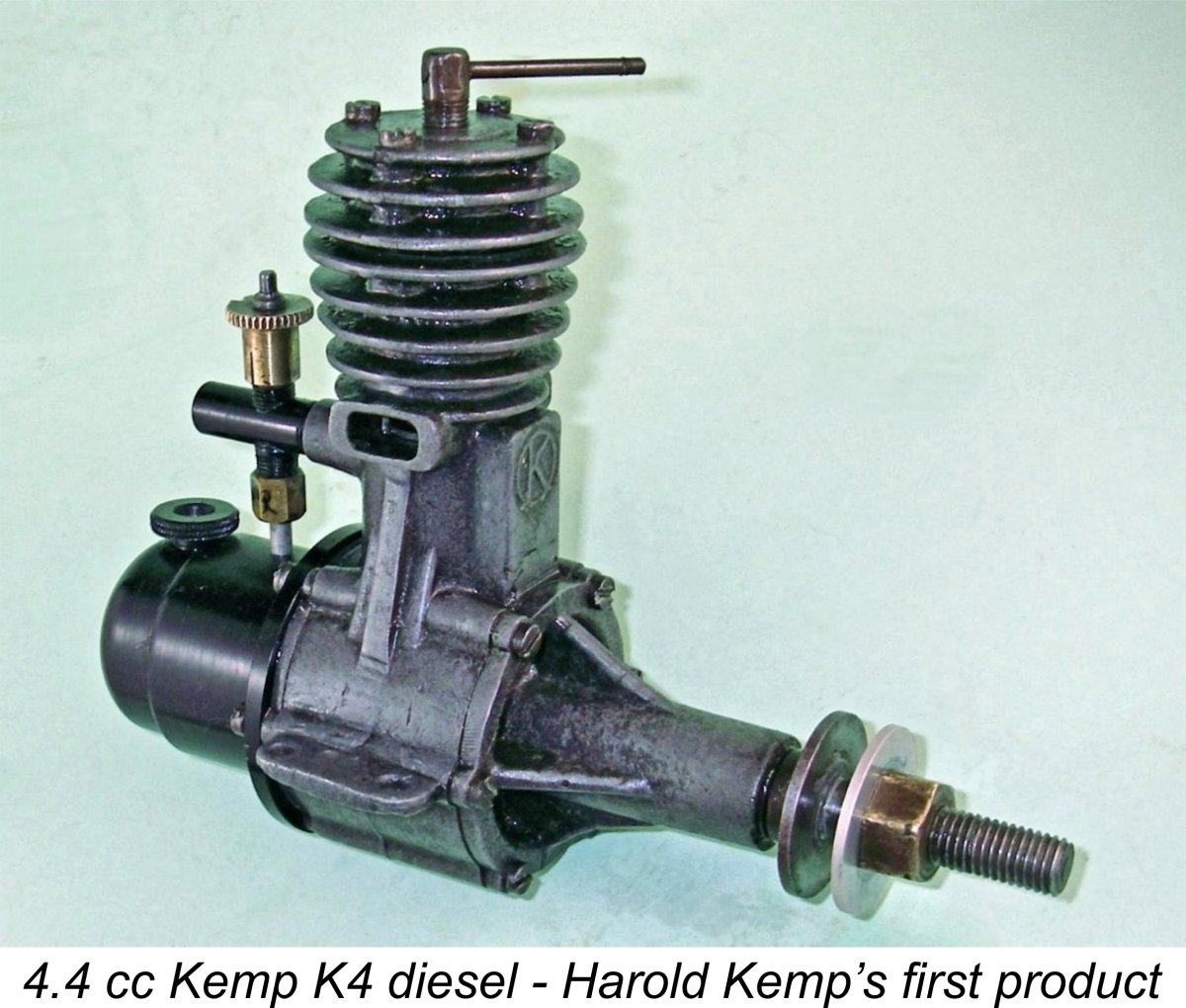
It’s always good to begin with the tale of the tape. The Kemp K4 was a long-stroke design having nominal bore and stroke dimensions of 0.625 inches (15.88 mm) and 0.875 inches (22.23 mm) respectively for a calculated displacement of 4.40 cc (0.269 cuin.) exactly. The illustrated original example of the engine weighs in at a notably hefty 11.11 ounces (315 gm) with tank. The other accompanying image shows the title block and materials call-out table which went with the previously-mentioned original drawing. This provides some very useful information relating to the engine’s construction. It’s actually quite possible and perhaps even likely that this table was drafted by Harold Kemp himself.
As many of us know to our cost, magnesium alloy has an incorrigible tendency to want to return to its elemental state in the form of corrosion! Harold Kemp's attention was evidently drawn to this problem early on, leading him to quickly introduce a revised Series II version of the engine. This was little changed from the original model, being still based upon the same magnesium alloy castings. However, the castings now received a black surface finish which did much to reduce their tendency to corrode. The manufacturers of the Mills engines later adopted a similar strategy when the switch was made to magnesium castings in 1948.
I suspect that this was in fact how the black finish was produced throughout – it seems unlikely that a small operation like Kemp Engines would have gone to an anodizing or chromate process when a far simpler and more easily produced surface finish was available. Contrary to a seemingly widespread impression, the later Mills engines did not use anodizing either – their black protective finish was produced through a chromate dip process. Regardless of how the black finish was actually produced, this version of the engine soon earned a very good reputation for being both well made and reliable. Accordingly it became a steady seller, albeit in the relatively minimal quantities dictated by the production limitations of the very small workshop in which it was made. The company was evidently able to sell all the engines that it could produce and could possibly have sold more, at least initially. The final variant of the engine featured castings which were formed in aluminium alloy - the ultimate response to the magnesium corrosion problem. However, oddly enough the engines continued to receive a black surface coating despite the fact that this was no longer required for corrosion protection. It seems that the black case had become something of a Kemp trade-mark look, at least for this model.
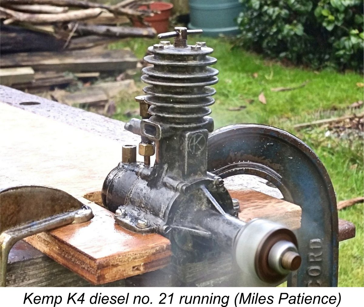
Once the company began to number its products, it seems that the numbering sequence was started at engine number 1, since Miles Patience owns engine number 21. This example has the black-finished magnesium case, reinforcing the impression that the numbering may have started when the black finish was introduced quite early on. Miles also owns aluminium-case engine number 543, which is presumably a very late example. More of that particular unit below. O. F. W. Fisher reported the existence of engine number 522 in his well-known 1977 book "Collector's Guide to Model Aero Engines". These are the only serial numbers which have so far come to my attention. In terms of its overall layout, the K4 was a conventional side-port long-stroke design of the pattern which was more or less mainstream at the time. The massive main casting incorporated the crankcase (which was open at both ends), an internally threaded stub for the intake venturi, the single bypass passage, the twin exhaust stacks and the upper cooling jacket all formed in a single casting. The cylinder portion was The magnesium head casting was centrally drilled 13/32 inch diameter to accept a pressed-in internally threaded mild steel bush which accommodated the compression screw. The latter component was a conventional L-bar design having an unusually fine ¼-40 ME (Model Engineer) thread – good for fine compression adjustment. The compression screw acted upon an unhardened mild steel contra-piston (charmingly termed the "obdurator" on the plans). Curiously, the contra-piston featured very thin 0.037 inch walls, similar to the far later DCO contra method which is fully described on MEN. The piston was a lightweight two-piece assembly of somewhat unusual construction. A steel gudgeon pin carrier (or yoke) was topped with a spigot which was externally threaded ¼ BSF to serve as a yoke pin. After the rod and gudgeon pin had been installed in the yoke, this pin was threaded (tightly) from below into an internally threaded hole in the crown of a lapped hardened steel sleeve which acted as the working piston. Following installation, the yoke pin was lightly peened in place to assure that the two components stayed together. A wise provision seeing that the thickness of the piston crown was a mere 1/16 inch! The ¼ BSF thread was a somewhat odd choice for this application in that it had a relatively coarse pitch of 26 TPI. This meant that the crown of the working piston would have had a mere 1.6 threads to hold it, always assuming that the die could run right down to the shoulder of the yoke pin! We might consider the ¼-40 ME thread used elsewhere in the engine’s construction to have been a better thread for the yoke pin. No doubt Harold Kemp would have been able to give us a good reason for his design choice. One suspects that it was the peening rather than the thread that really secured the assembly. Be that as it may, the result of this arrangement was that the ends of the gudgeon pin were fully contained within the piston walls, thus being prevented from fouling the rather large induction and transfer ports. A worthy goal to be sure, but the assembly posed serious difficulties if the need ever arose to replace the connecting rod and/or gudgeon pin. The front edge of the piston crown corresponding to the transfer port incorporated a small chamfer which had the dual effect of increasing the transfer period somewhat and also providing some directional control of the incoming mixture.
The rather massive crankshaft was machined in one piece from nickel steel, being drilled axially to reduce weight. Following machining, it was hardened. The very substantial crankweb was conventionally counterbalanced through the provision of crescent-shaped cutaways on each side of the crankpin. The shaft was supported by two separate cast-iron bushings which were pressed into either end of the main bearing casting. Reference to the previously-reproduced G/A drawing will make this clear. The shaft in my example is a perfect fit in its bushings. The main bearing housing was formed integrally with the front crankcase cover. This was another substantial magnesium casting which was very well secured to the main casting by six 6 BA screws. It included four substantial braces for the main bearing housing. Somewhat unusually, the prop driver was a plain disc with no knurling for improved grip. The front of the crankshaft was stepped down from the 0.375 inch diameter main journal to 0.312 inch diameter, the latter portion being threaded 5/16-40 TPI - an unusually fine prop mounting thread! Most examples encountered today have a simple propnut and washer combination to secure the airscrew, but Paul Rossiter's previously-illustrated example has a magnesium alloy spinner nut. It's unclear how many of these engines were so equipped. Somewhat oddly, the prop driver was not mounted on splines or a taper as we might expect - it merely butted up against the step in the front of the crankshaft, thus creating what amounted to a friction joint between the shaft and the prop. While this might well protect the shaft in the event of a crash, it might also be expected to cause problems with starting. However, I experienced no slippage difficulties when testing my own example (see below). The same approach was used in the contemporary ETA "5" diesel. The crankcase was sealed at the rear by a cast magnesium backplate which was very well secured using the same six bolt pattern as the main journal casting. This must have been faced at the rear, since the large cast magnesium fuel tank replicated the bolt pattern and was secured as a simple butt-joint against the backplate by the 6 BA screws.
The two numbered examples owned by Miles Patience both have measured venturi throat diameters of 0.152 in. This represents a 23% increase in effective throat area - a very worthwhile gain.
The rear face of the intake venturis on some examples had a one-sided flange like that often seen on Westbury carburettors for drilling and tapping to take a swinging shutter-type choke plate, although none was fitted to any known examples. Miles Patience's engine number 21 is equipped with such an intake, as is Paul Rossiters' un-numbered example. Other examples (like my own engine and Miles' engine number 543) do not display this seemingly redundant feature. The vertical sections of the intake venturi casting were externally threaded ¼-40 to accommodate the needle valve thimble on top and a brass fuel pickup tube/nut assembly down below. The venturi threaded into the crankcase boss using a 5/16-40 thread. No lock-nut was fitted, making air leaks appear likely unless the thread was very carefully cut or some form of sealant was used. The fine thread used would undoubtedly assist in aligning the brass fuel pick-up tube with the hole in the tank. On the factory drawings, the needle valve is shown as comprising a needle-pointed length of 0.1" diameter silver-steel rod, threaded 7 BA at the blunt end to screw into a split thimble in which it was secured with a lock-nut (the outside diameter of a 7 BA thread is 0.098 inch, so this makes perfect sense). Production engines seem to have abandoned this expensive design in favor of soldering the needle in place, as seen on my own illustrated example and on the G/A drawing. Moreover, the diameter of the rod from which the needle was formed was evidently reduced - the needle in my example has a measured diameter of only 0.078 in. The needle seat and jet were formed by a length of 3/32 inch O/D copper tube pressed into the lower part of the venturi casting so as to project slightly into the carburettor bore. A note on the plan states (in part) "Close end to suit needle".
As can be seen in the illustrated modern reproduction, with the actuating arm vertical, the cam action of the lower part of the arm draws the needle upwards, compressing the spring and hopefully locking the needle into the thimble so it will not move vertically, while still being somewhat free to pivot. In this state, the needle thimble will move the needle up and down in the usual manner, although the needle itself can rotate in the carrier—an important factor as we shall see. Whether they were of the Auto-Knipps, E.D. clockwork or air-hydraulic types, British timers of the day generally exerted a pull when activated. In practical terms, their activation would generally result in a line being pulled rearwards along the airframe axis. In this instance, such a line would have been connected to the hole in the top of the cam arm. To function, the cam arm needed to be oriented so that the slot was aligned fore and aft. When the timer activated and pulled the line, the arm was then free to swing backwards. As it passed over-center, the spring would assist its further progress, snapping the needle down onto the jet seat and thus cutting off the fuel supply. Tricky and fiddly to make, assemble and adjust. Plus as a bonus, air leaks would be almost inevitable, making repeatable and stable needle settings highly uncertain. Miles Patience confirmed this latter point when attempting to test his engine no. 543 which is fitted with this assembly. He was unable to get the engine going at all using the cut-out needle, hence having to use the standard needle from his companion engine no. 21 to conduct his test (see below).
In terms of its production life, it's fairly well established that the K4 first appeared in early 1947, as noted earlier. The date of its departure from the scene can also be established with some certainty. The best evidence is to be found in the series of advertising placements by Henry J. Nicholls which appeared regularly in "Aeromodeller" magazine. As previously recorded, Nicholls was a major retailer for the Kemp engines. The K4 was included in Nicholls' advertisements up to the end of 1947, as reflected in the attached advert from the November 1947 issue. However, by the time of Nicholls' February 1948 advertising placement, it had been removed from the otherwise comprehensive list of available diesels. It thus appears certain that the manufacture of the K4 had ceased as of late 1947. The engine's availability was evidently confined to the year 1947 for a production period of only some ten months or even less. Some potential reasons for such a short production life will soon become apparent ............ The Kemp K4 On Test The rarity of the Kemp K4 diesel is such that I honestly never expected to have the opportunity to conduct a full test of the engine. However, the prospects suddenly improved in mid 2016 when a seemingly pristine example of the engine appeared on eBay UK. The seller was only prepared to ship within the UK, but fortunately my late valued friend and fellow Kemp enthusiast Paul Rossiter was willing and able to bid on my behalf from his location in South Wales. In this roundabout way I was successful in acquiring the illustrated example of the engine for direct examination and test. My very sincere thanks to my mate Paul - he is missed! The engine was offered and illustrated as being in complete and original condition. As far as its main components went, a direct examination following receipt confirmed this to be true. In fact, the engine appeared to have seen relatively little use, remaining quite tight by "feel". However, there were a few flies in the ointment! Firstly, the tank appeared to be an accurate replica item, since it was machined rather than being cast. Looks very nice indeed, but I don't think it's original. In addition, upon looking through the exhaust ports it was apparent that the cylinder had been installed well out of its correct axial alignment – the ports were over half-closed, as was the induction port when viewed through the intake venturi. Clear evidence that the engine had been tampered with by someone with an imperfect understanding of model engine assembly! And there was more such evidence lurking in the wings ........... read on! I removed the cylinder head and restored the correct cylinder alignment with the transfer port at the front, the induction port at the rear and the two exhaust ports at the sides. All four ports proved to be cleanly-cut rectangular openings of quite generous proportions. Upon reassembly the engine felt very good, with excellent compression and a healthy pop from the transfer when turned over. The piston fit felt a little tight, but that was something that I'd have to live with. Next step was to try getting the beast going. Long and at times frustrating experience with large diesels has convinced me of the benefits of using a heavy prop with plenty of flywheel effect for those initial starts. This is because large diesels, particularly those of the plain bearing variety like this one, have a decided tendency towards self-braking due both to their high levels of friction drag and their very considerable compression resistance. The heavy prop overcomes these issues very effectively.
After setting the needle by guesswork, I gave the engine a couple of choked flicks, primed the cylinder and set to work. The K4 started firing almost immediately, but the compression was clearly set too low for continuous running. A modest increase soon produced a start, however. Once running, it turned out that I’d guessed the needle setting pretty closely – only a minor adjustment was required. The engine ran very smoothly indeed without any trace of misfiring or harsh running. As the cylinder warmed up, it was necessary to reduce compression considerably. This is actually a common characteristic of large low-speed diesel operation – they often require a higher compression setting for cold starting than they do for running. Subsequent cold restarts followed the same pattern – a compression increase was always required. However, if this requirement was met, the engine proved to be a very easy starter indeed, displaying no vicious tendencies whatsoever and requiring only a few flicks to get going. A small prime continued to be very effective for cold starts, while a few choked turns at the running compression setting invariably sufficed for instant hot restarts. Response to both controls was very positive without being unduly critical, making optimum settings extremely easy to establish. I'd objectively rate this as a very user-friendly engine indeed. After a couple of runs to settle things down, I checked the tightness of all assembly screws and then measured the speed on the APC 14x6. Using this prop, the engine turned out to be running at a mere 3,300 RPM – around 0.042 BHP at that speed. Expecting things to pick up a lot with a lighter load, I switched to an APC 12x7. Starting remained just as easy, but the output did not improve nearly as much as I had expected. The engine could only manage around 3,900 RPM on this prop – about 0.052 BHP. It continued to run very smoothly and steadily, but the power just wasn’t there. Even the relatively lacklustre albeit slightly larger Delong 29 diesel tested earlier had managed 5,200 RPM on the same APC 12x7 airscrew from my test set. These were disappointing preliminary results, to say the least. However, I had serious difficulty believing that the engine could really be that gutless! I removed it from the stand and took it back to the workbench for further examination.
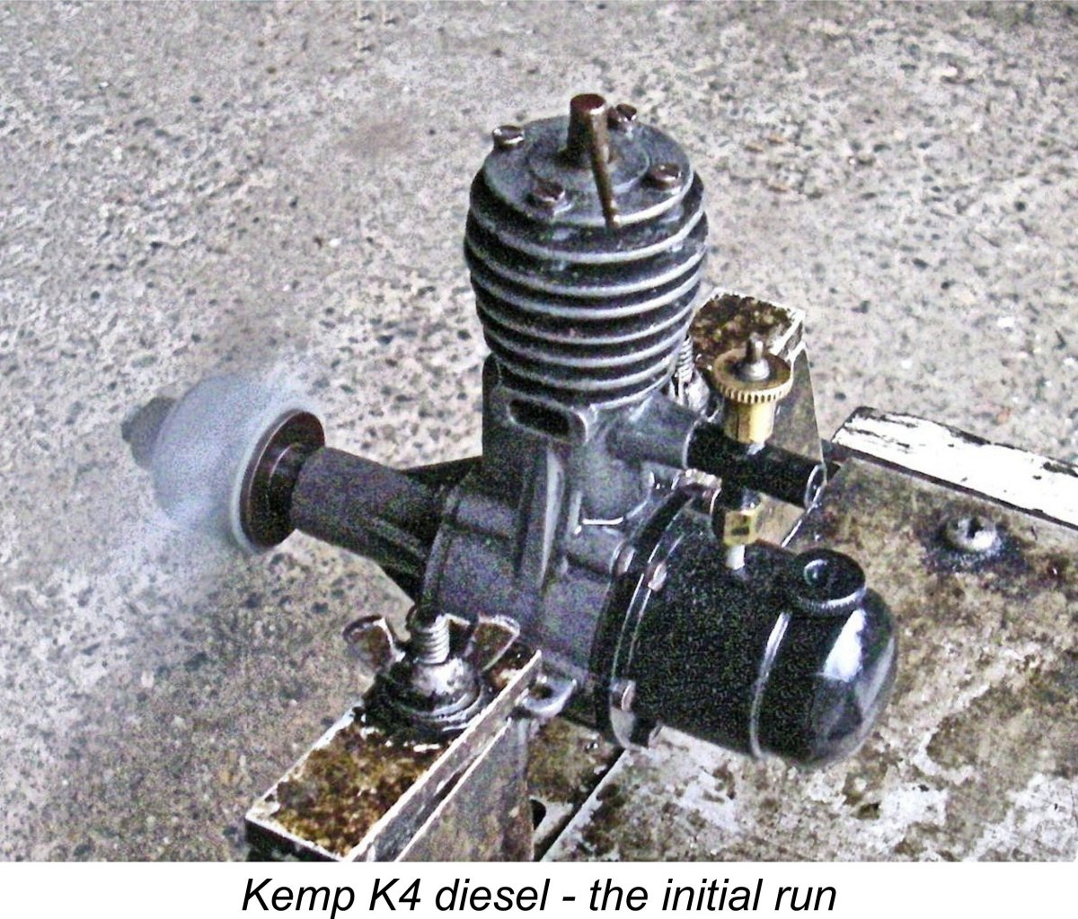
I removed the front cover to check and found that external appearances did not lie - there was indeed a large cutaway at the point in the front cover installation spigot where the extra metal had been included in the casting. The bottom of the piston skirt came down almost all the way to the outer diameter of the installation spigot at bottom dead centre, but that was actually the least of the problems - the intrusion of the front cover installation spigot into the crankcase effectively blocked most of the lower entry into the bypass passage, and the descending piston skirt merely blocked what little was left! The net result was that as assembled, the entry to the bypass was greatly constricted at all times and was almost completely blocked at bottom dead centre! To perform its function of allowing completely free gas access to the bypass passage, the cutaway clearly has to be located at the top. Some former owner (probably the same one who installed the cylinder liner incorrectly) had attached the cover with the cutaway at the bottom! The result was that the bypass was essentially strangled by the front cover installation spigot. No wonder the poor beast lacked power – in fact, it’s a wonder that it went as well as it did. It could actually have been forgiven for not running at all …………. The inescapable conclusion to be drawn from this is that the poor old Kemp had spent some time in the hands of that most dangerous of owners - the guy who thinks he knows how to dismantle and re-assemble model engines …………and doesn’t! Unfortunately, such owners’ mistaken belief in their own capabilities almost always seems to impel them to dismantle their engines “just for a look” and then to reassemble them incorrectly. If you don’t really know what you’re doing (which is a very different thing from merely thinking that you know what you’re doing), please leave well alone! The assembly threads for the various screws can only take so many re-fittings before the threads become worn or, worse yet, stripped. This is actually a very common situation with engines offered on eBay. It’s always astonished me how rarely I get an engine through eBay that is in fully-sorted glitch-free condition. So many of them (even the ones that are advertised as being in New or Excellent condition, or even occasionally NIB) have issues of one sort or another that need fixing, almost invariably relating to less-than-knowledgeable tampering. People seemingly can’t resist the urge to take a peek inside, and all too often their re-assembly efforts are imperfect. My test example of the Kemp K4 is a classic example. I guess that a lot of owners don’t actually run their engines after tampering with them! As an aside, another matter which never ceases to amaze me is the number of engines which are offered on eBay without being cleaned up by their sellers. Many such engines look so much better following clean-up that they would amost certainly attract more competitive bidding if they were offered in that state. Moreover, their true mechanical condition is far more readily assessed if they are free from storage residues and the like. Perhaps that's the idea .......... Anyway, with the front plate alignment problem sorted, I reckoned that the Kemp was ready to show what it could really do! So back into the test stand it went. It started up again just as readily as before on the massive 14x6 APC prop. However, I was greatly chagrined to find that the realignment of the front housing had had a minimal effect on the speed achieved with this prop - the engine ran very smoothly and steadily at 3,400 RPM for an improvement of only 100 RPM! The same was true of the 12x7 APC, which beat its former 3,900 RPM speed by only 100 RPM also. Running remained extremely smooth and consistent, while the engine continued to be very responsive to the controls, hence being extremely easy to set. The problem was that there simply wasn't a setting that allowed for the development of significant power! Oh dear! These were quite discouraging figures! Hoping for better things with lighter loads, I carried on Looking at these results, it's apparent that the K4 benefited very minimally from the sorting-out of the bypass problem. This in turn clearly implied that the bypass wasn't the limiting factor at work here. There was evidence to suggest that the transfer process was somewhat less than efficient, as the accompanying strongly backlit photo will attest! Most of the smoke that is visible in this leaned-out shot is unburned fuel vapour, as a well-trained diesel nose can easily detect. There's clearly a significant short-circuiting problem, with a good proportion of the mixture discharged from the transfer port going straight out the exhausts without ever reaching the combustion chamber. Even so, the liquid exhaust residues were very clean, showing no evidence of a serious combustion issue - the fuel that did reach the combustion chamber appeared to be burning very cleanly. There was also no observable tendency to detonate. I'd used the same fuel for other tests as well as this one, so I knew that the fuel was OK. The cylinder porting areas all seemed quite adequate. Consideration of the above factors left only one suspect in addition to the fuel short-circuiting issue noted earlier - the induction system must surely be contributing significantly to the power "bottleneck". A strong hint that this was the case came from the fact that the engine would run for well over 7 minutes (!!) on a tank at its peak of around 4,400 RPM using the 12x5 prop! For an engine of this displacement, fuel consumption was minimal, to say the least. In order to make power you have to burn fuel, and the rate at which this engine could absorb fuel simply wasn't conducive to high power development. To make matters worse, it was clear that the engine was failing to burn a significant proportion of the fuel that it did absorb, as noted earlier. The induction problem was almost certainly down to the measured 0.137 in. (3.48 mm) dia. intake venturi, which is very much on the skinny side for an engine of this displacement with no sub-piston induction. The area of such a throat is only 0.0147 square inches (9.51 square mm). Even allowing for the end taper, the presence of the 0.078 in. dia. needle which traverses the opening removes around 58% of this, leaving the engine drawing its fuel mixture through an aperture having a combined area of only 0.0061 square inches (5.51 square mm). Other pioneering diesels of comparable or even significantly lesser displacements typically have far greater venturi throat areas than this! Basically, the poor old Kemp was effectively being strangled at birth by its own venturi! It had been my plan that my valued friend Miles Patience would bring his own example no. 543 over for testing during a January 2017 visit to my area to see relatives who live nearby. Miles did indeed bring his engine with its 0.152 in. dia. intake, but unfortunately some technical issues prevented us from testing it on that occasion to measure the effect of a slightly larger induction venturi. This left it down to me. A really close look at the intake of my engine revealed that the constriction was at least in part due to the fact that a considerable thickness of the black surface coating material had run into the intake and set at the venturi constriction. I reasoned that skimming this off down to the metal could do no harm, so I proceeded to do just that, carefully using a suitable series of appropriately-sized hand-activated drills. To my surprise, it took a #24 drill of - you guessed it - 0.152 in. dia. to remove the last vestiges of that material! It seems that my engine too has a venturi of that diameter - it was just compromised by the presence of that excessive surface finishing material. So, back into the test stand yet again went the hard-working but hopefully somewhat happier Kemp, now benefiting from a 23% increase in effective choke area! Couldn't hurt the cause....... The first run on the APC 14x6 was most discouraging - using the same fuel, I got an unchanged reading of 3,400 RPM! Hmmm ..... however, the 12x7 ran some 100 RPM faster than before, which gave me some hope. The same was true of the other props tested - as the load went down, the speed went up by a steadily increasing margin. The following data ended up being obtained:
It's clear that the K4 benefited from the opening-out of the intake - it would now beat 5,000 RPM on several of the tested props. Moreover, the engine's easy starting, excellent control response and smooth running were all unaffected. This example appears to have had little previous running, since it still feels relatively tight. I suspect that it could potentially do a bit better than this with more running time. That said, a hardened steel piston in a hardened steel cylinder will take forever to free up ........... Even so, the implied peak of around 0.070 BHP @ 4,700 RPM with possibly a little more to come with running time still represents a new low bench-mark for an engine in this general displacement category. The previous holder of this dubious record was the Reeves 3.4 cc diesel (actually a 3.14 cc unit), but even that model managed to develop 0.094 BHP @ 5,500 RPM from its s In the end, it appears to have been an unusually inefficient transfer system that really let the engine down in performance terms. The bevelling of the upper edge of the transfer port to match the existing bevel in the piston crown might well have provided improved directional control of the incoming mixture, with a consequent performance improvement. The output developed by the K4 as tested is in the same range as typical 1.5 cc - 2 cc diesels of its pioneering era (early 1947). The engine's only edge over those smaller and lighter units would have been the fact that it developed its peak power at very low RPM, hence being able to swing a far larger and potentially more efficient airscrew. Either a 13x5 or 12x6 would suit it nicely. After his return to England, Miles Patience dealt with the issues which had prevented us from running his K4 no. 543, after which he proceeded to put it through its paces. He also tested his other example no. 21, finding it to be actually a little faster than its still-tight companion. His results were as follows:
Although Miles' test was run using different examples of the same props, these figures are completely consistent with those obtained from my own un-numbered engine with its similar 0.152 in. dia. intake. Engine number 21 seems to be a little more powerful than my example, but not greatly so. It would appear that my rather unspectacular findings may well be fairly typical for this engine. My sincere thanks to Miles for taking the time and trouble to provide this confirmatory evidence. Despite its very low power, the engine is a very well-made, well-mannered and user-friendly powerplant which starts extremely easily and runs both smoothly and dependably. For many aeromodellers in that early period of diesel development in Britain, that would have been enough, at least initially. Conclusion
Consequently, the K4 was only offered in limited quantities for a relatively short time - the available serial number evidence suggests that no more than around 600 examples were made, probably within a period of less than ten months during 1947. Moreover, a proportion of those which were sold have doubtless been lost to corrosion. For all of these reasons, good examples of the engine are quite rare today. Paul Rossiter, Miles Patience and I all got lucky ............. As matters transpired, the K4 was only the first of a series of commercially produced engines made by Harold Kemp in his workshop at 7 Bank Street. Harold continued with smaller engines, producing the previously-mentioned 1 cc and 0.2 cc diesels in small production runs. The latter model proved very popular, being the smallest British production diesel of the time and a very fine runner too. It remains a much sought-after collectible today. After introducing a revised 1 cc model, the sideport Eagle, in early 1948, Harold sold the Kemp Engines business in mid 1948, with well-known control-line stunt flier Len “Stoo” Steward and his "K" Model Engineering Co. Ltd. taking over at the same premises, later expanding to a new location on nearby Darnley Street in Gravesend. The premises at 7 Bank Street are now (2018) incorporated into a wholesale conversion of the entire block into a series of flats. They are included in the Gravesend Heritage Quarter, meaning that the basic brick structure may well still be that which housed the Kemp Engines operation. However, Harold Kemp would not recognize his old haunts today!
There is some question as to the part, if any, that Harold Kemp played in the design and development of these later “K” series engines following the sale to Len Steward. Certainly, he continued to live at 3 Bank Street for several years following the sale, thus remaining geographically close to the ongoing business. His career as an engineer subsequently took a different but still highly productive direction. However, that was not until 1952, by which time the “K” series had come and gone. Sadly, Harold Kemp passed away in 1975, so obtaining a definitive answer to this question is now problematic. That said, it may be significant that the “circled K” emblem visible at the foot of the K4 drawing sheet and cast in relief onto the bypass of the K4 itself was retained by the new company as the logo cast onto their engines, suggesting some degree of carry-over. Regardless, we can state with certainty that the K4, the original Kemp 1 cc model and the original 0.2 cc Kemp Hawk were indisputably Harold Kemp’s designs, confirming his place of honour among the pioneers of British diesel development. For more personal details on Harold Kemp, please see the Harold Kemp Tribute page. __________________________ Article © Adrian C. Duncan, Coquitlam, British Columbia, Canada First published February 2017 |
||
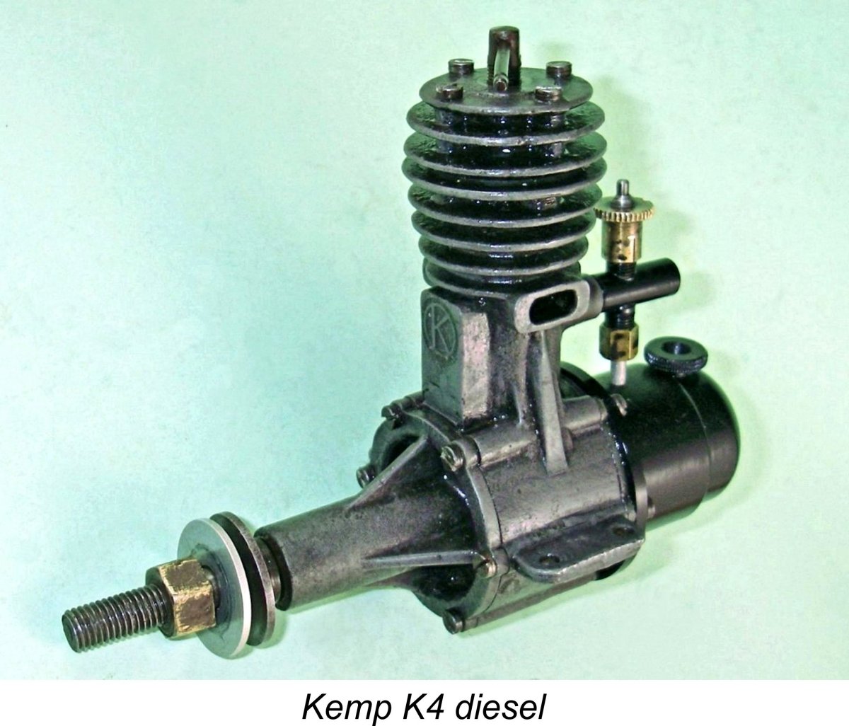 The establishment of the production facilities described above and the completion of design work and tooling seems to have taken up the latter part of 1946, with the first commercial product of the new company appearing on the market in early 1947. This was the Kemp K4 sideport diesel of 4.4 cc displacement which forms our main subject.
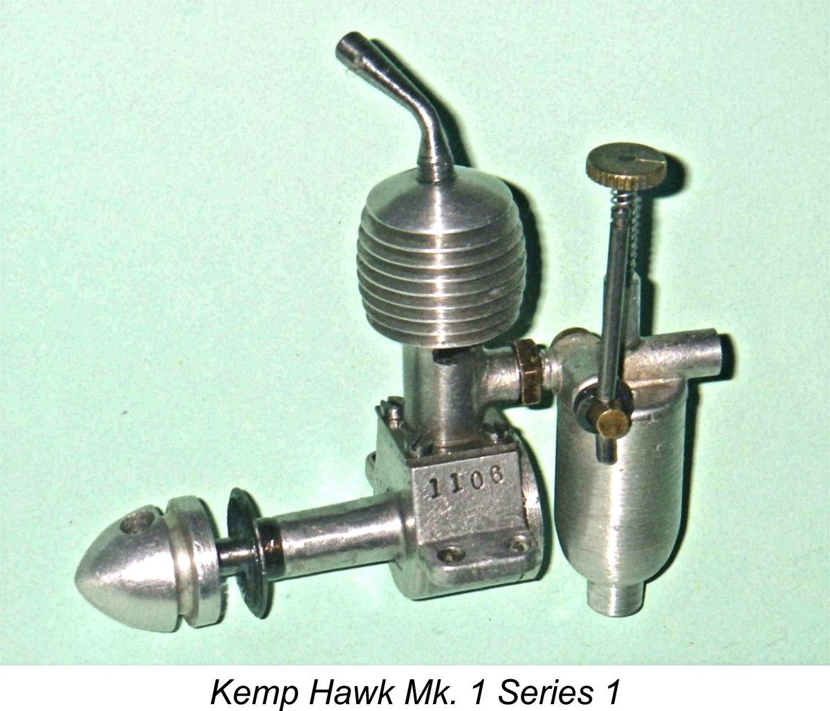 colloquially known as the "Black Devil" which was effectively two of the 4.4 cc engines joined together. This was labour-intensive to produce, consequently having to be sold at a very high price in order to generate a profit. There were few takers, as a result of which only a small handful of these were manufactured. The mega-rare survivors are highly prized collector's items today.
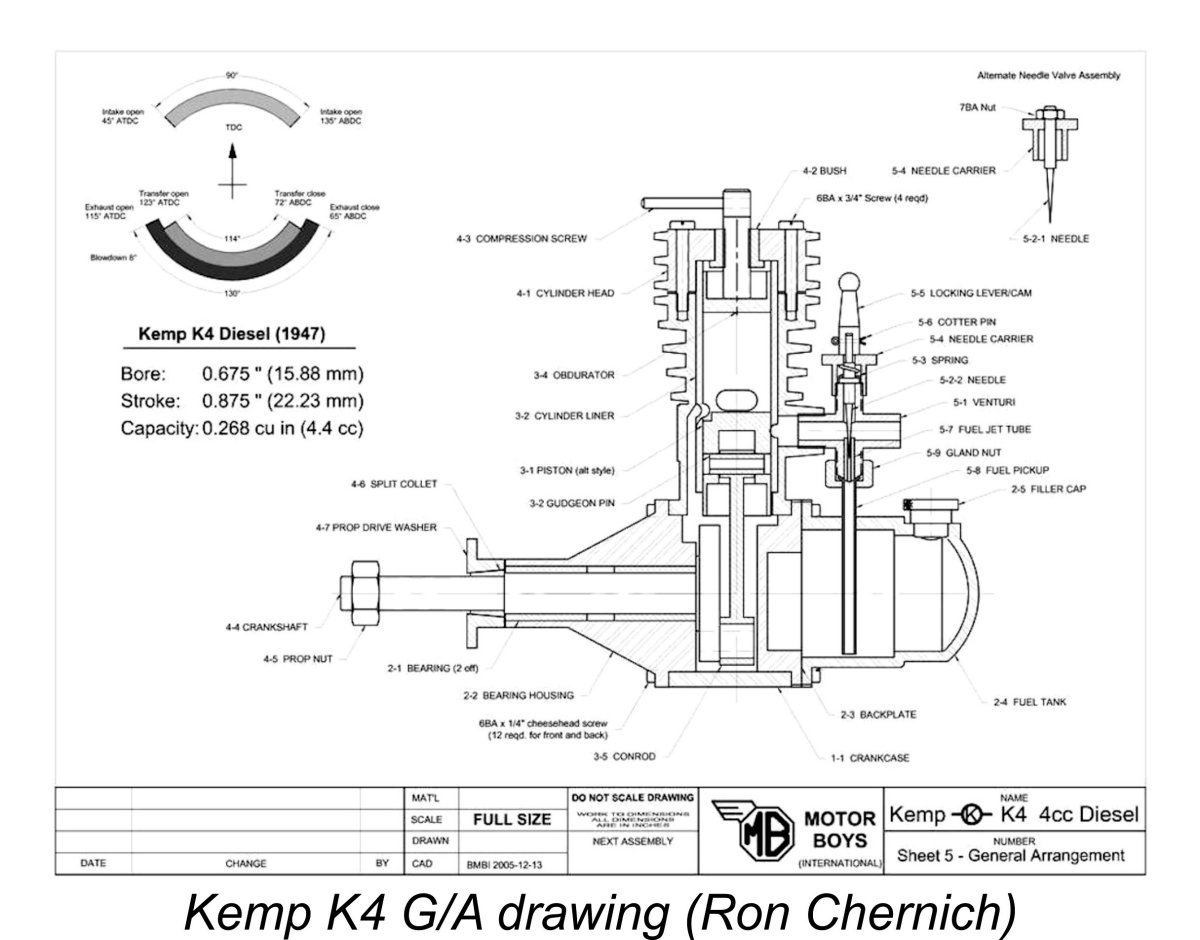 The fortunate availability of scans of a rather tattered original drawing for the K4 enabled the late Ron Chernich to redraw the engine using CAD, taking the usual liberties to simplify construction for modern times while retaining the outward appearance of the original. The accompanying General Arrangement (G/A) drawing shows the re-drawn engine, although the details that follow reflect the original design except where noted.
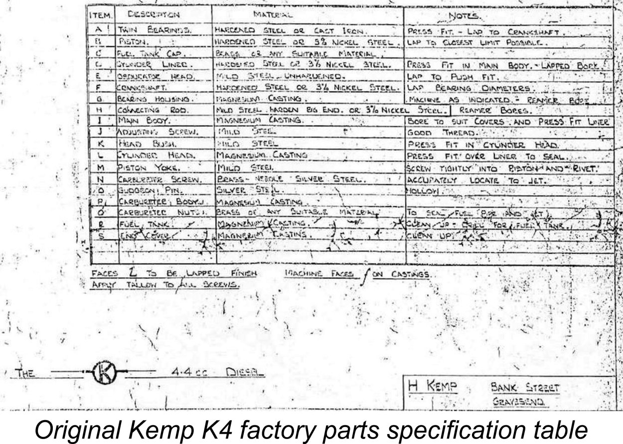 The K4 was based on a number of quite intricate die castings. The castings for the Series I version of the K4 were initially produced in plain magnesium alloy. My own illustrated example of the engine is one of the plain magnesium alloy Series I models, although it has a seemingly replica tank of the black-finished variety.
 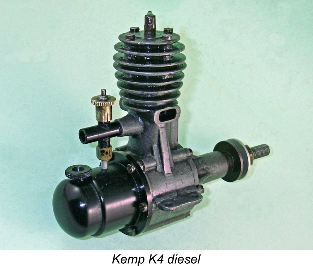 It has been stated by a few commentators in the past that the black surface finish on the Kemp magnesium castings was produced by anodizing. However, all examples that I have encountered have been given some kind of extremely hard and durable black surface coating. The two examples owned by Miles Patience both display such a finish, as does the seemingly replica tank on my example.
 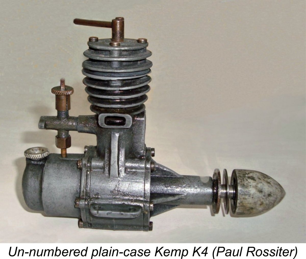 Most of the engines appear to have borne serial numbers, although my seemingly early example does not display such a number. Neither does the unpainted and presumably early example formerly owned by my late friend Paul Rossiter. It would appear from this that the early engines with their plain unpainted magnesium castings did not receive serial numbers. The application of such numbers appears to have begun with the introduction of the second variant with its painted castings.
 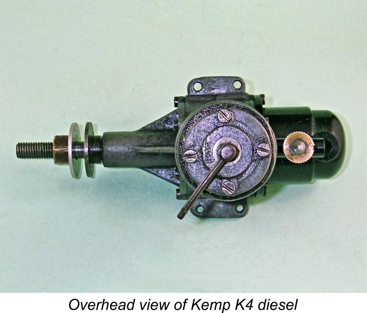 axially bored out to permit the installation of a simple tubular drop-in steel cylinder liner which was located by a lip at the bottom of the installation bore. The liner was secured by a substantial finned cast magnesium cylinder head which was held in place by four 6 BA screws.
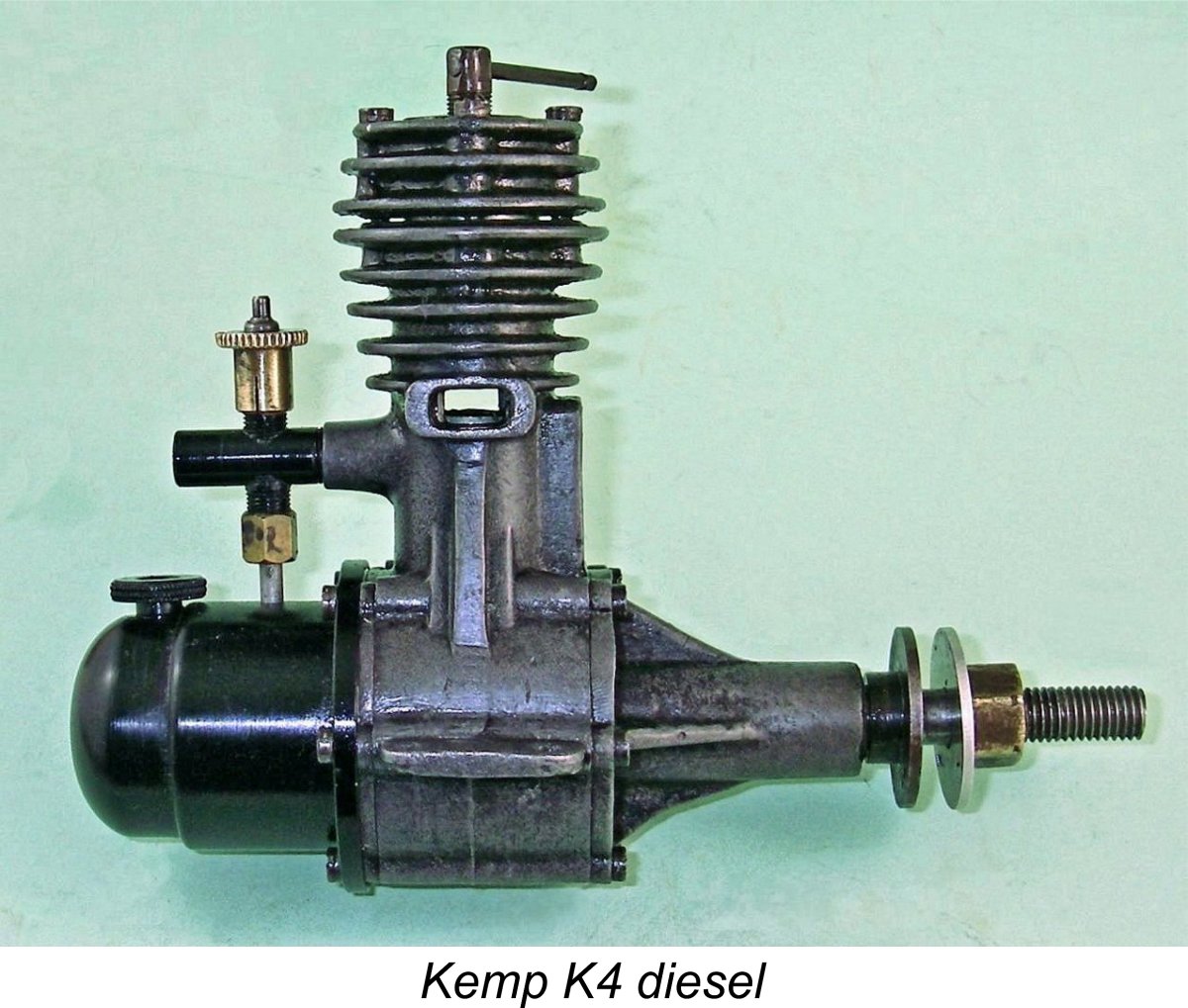 The connecting rod was made either of case hardened mild steel or 3% nickel steel, with a hardened big end. The big end was reamed to
 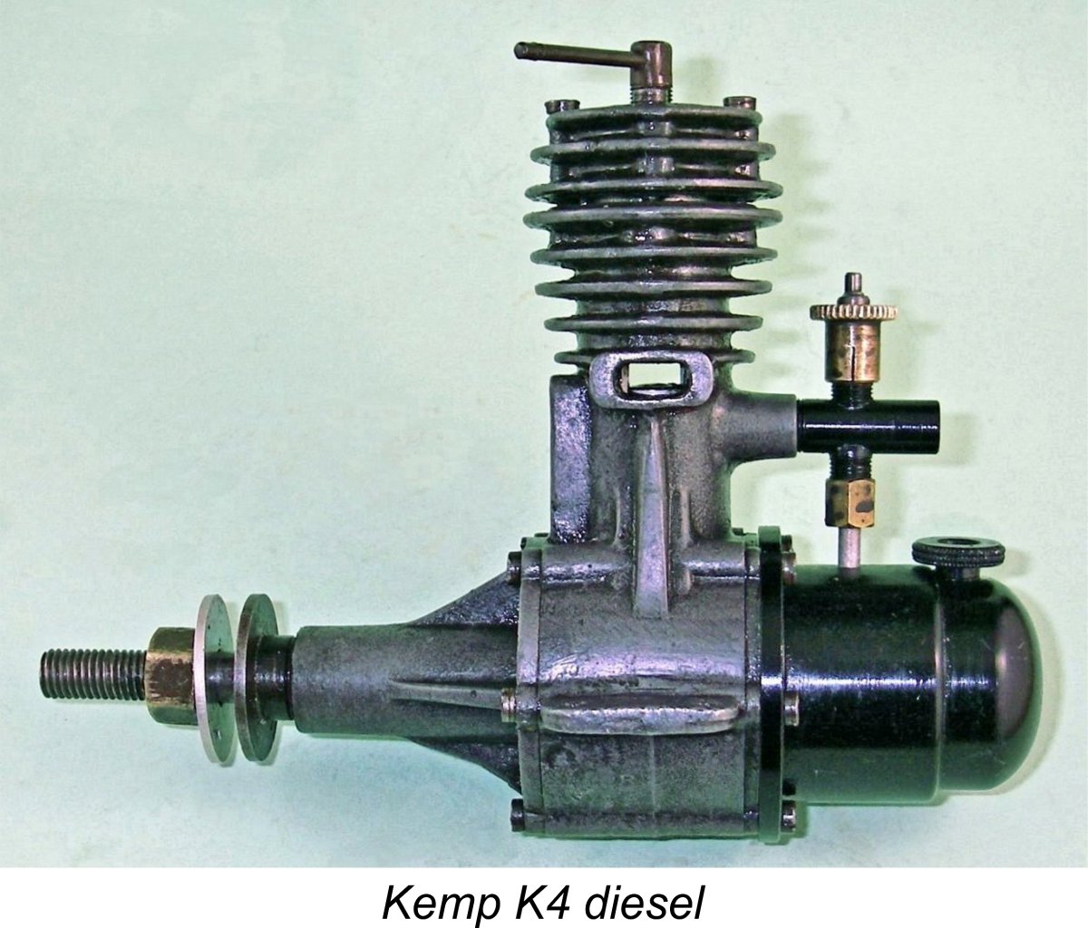 The intake venturi was yet another magnesium casting of
 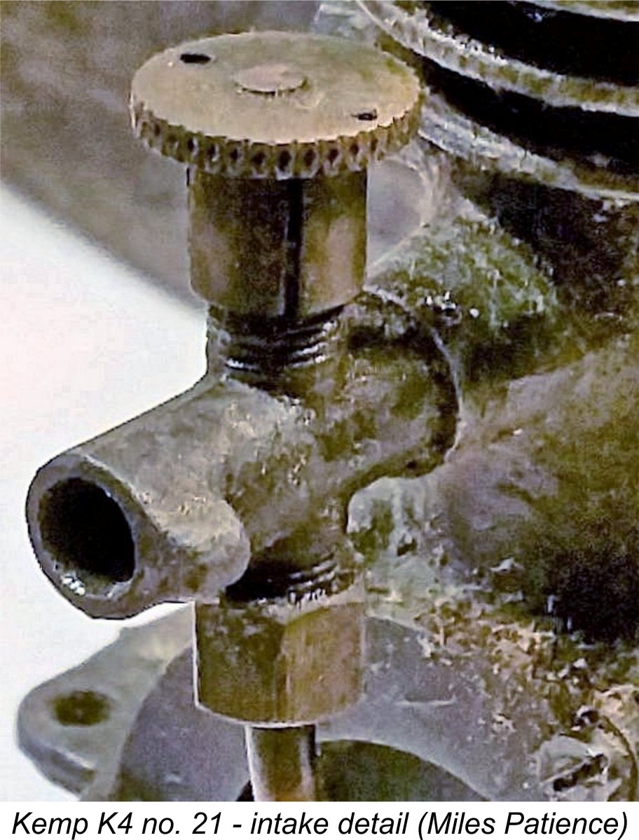 Interestingly, Ron Chernich stated that the intake on these engines was drilled through with a #18 drill bit, which is an even more rational 0.1695 in. dia. It's not clear whether Ron's information was derived from an unmodified original example or one which had been subject to owner modification. Regardless, this would provide a venturi throat area which is over 50% greater than that on my example. We will have occasion to recall these figures in a later section of this article.
 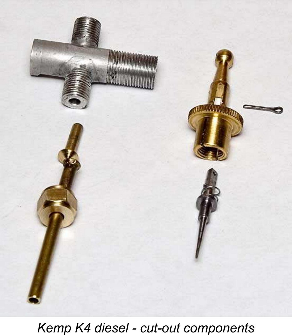 Evidence exists in the form of an example in Eric Offen's collection as well as Miles Patience's engine number 543 of a more interesting assembly intended to provide a fuel cut-out, a popular feature for free-flight work and very necessary in this case given the size of the K4's massive tank. This may have been an optional feature. It certainly was complicated and intricate, consisting of a spring loaded needle with an over-center cam-operated lever which was drilled to take an actuating wire or thread.
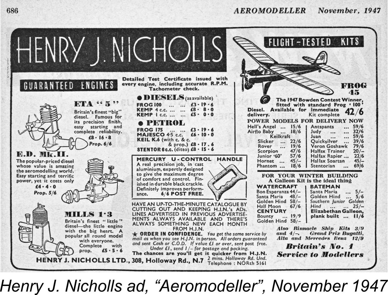
 I therefore began my encounter with the K4 using an APC 14x6 prop. This is a monumental club of an airscrew which will carry over any adverse loading which a model engine of this displacement might throw at it! I wasn’t expecting this to be a suitable prop for using the engine in flight service, but I did expect that it would aid my initial starting efforts.
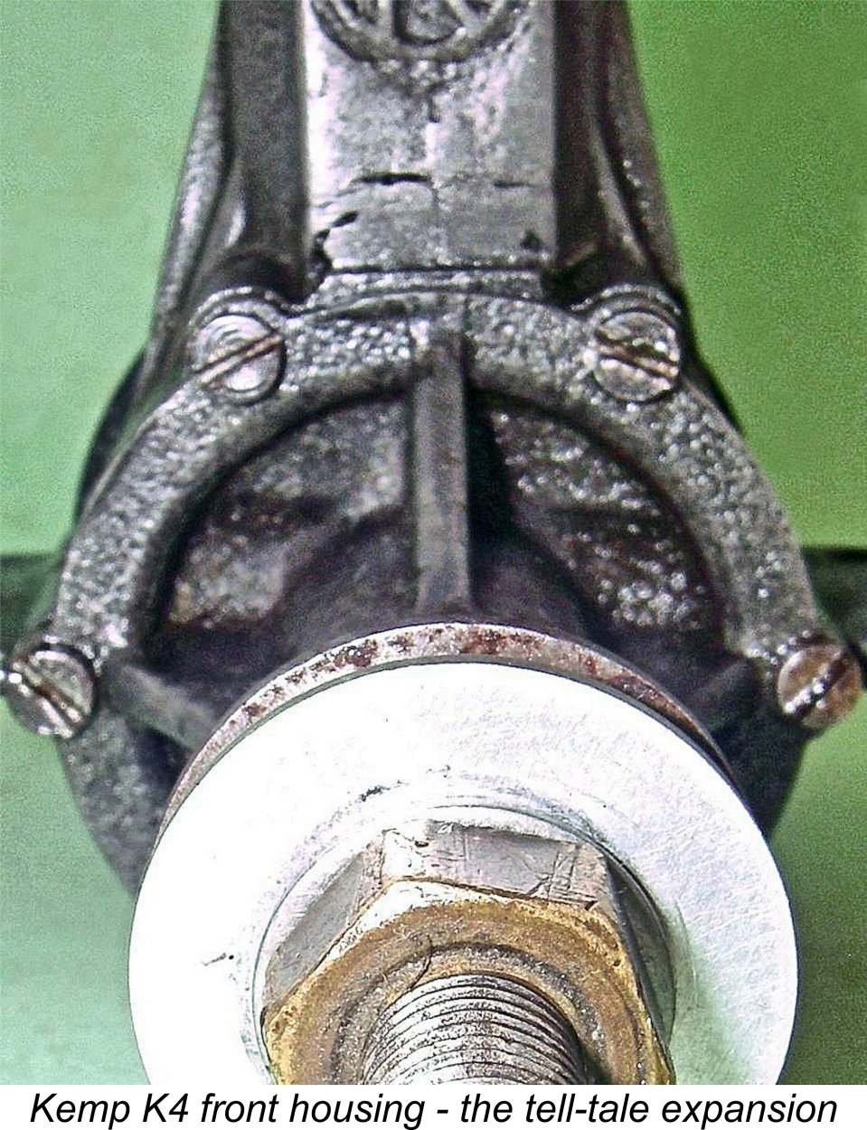 After staring at the engine from all angles for some time, the light finally dawned! I suddenly realized that the front cover incorporating the main bearing is a one-way fit – there was clear external evidence of an internal cut-away in the front cover’s installation spigot which was designed to be located at the bypass entry location at the top but was located near the bottom as assembled. The extra material provided in the casting to accommodate the cutaway is clearly visible externally if one looks carefully (which I didn’t initially!). The evident intent was to ensure good gas access to the lower bypass passage.
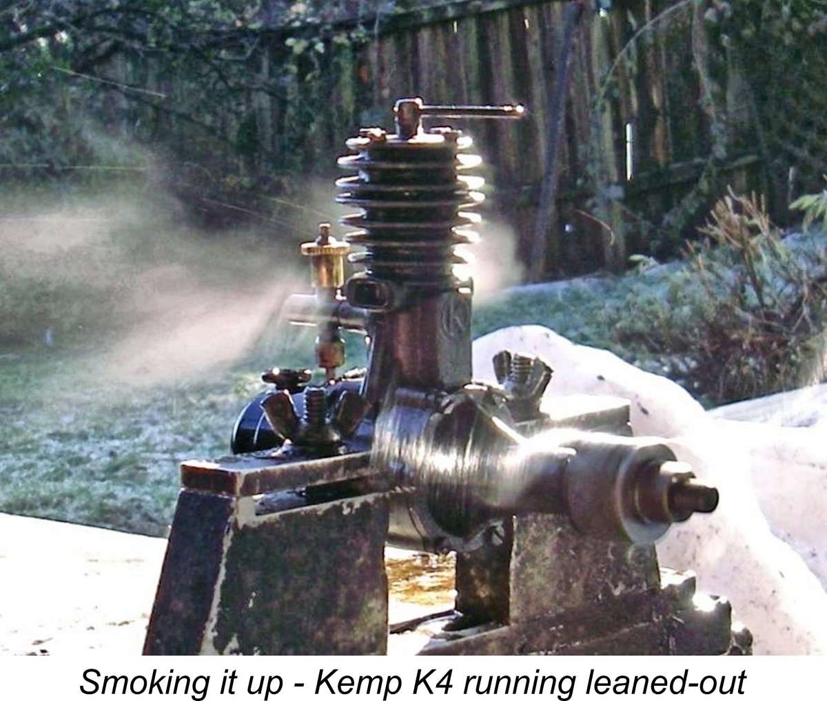 with the test, only to find that the the engine simply didn't want to run much above 4,500 RPM however lightly loaded. Even on the 10x6 APC prop, it wouldn't break 5,000 RPM. The figures obtained suggested an output of around 0.062 BHP @ 4,500 RPM - nowhere for an engine of this displacement.
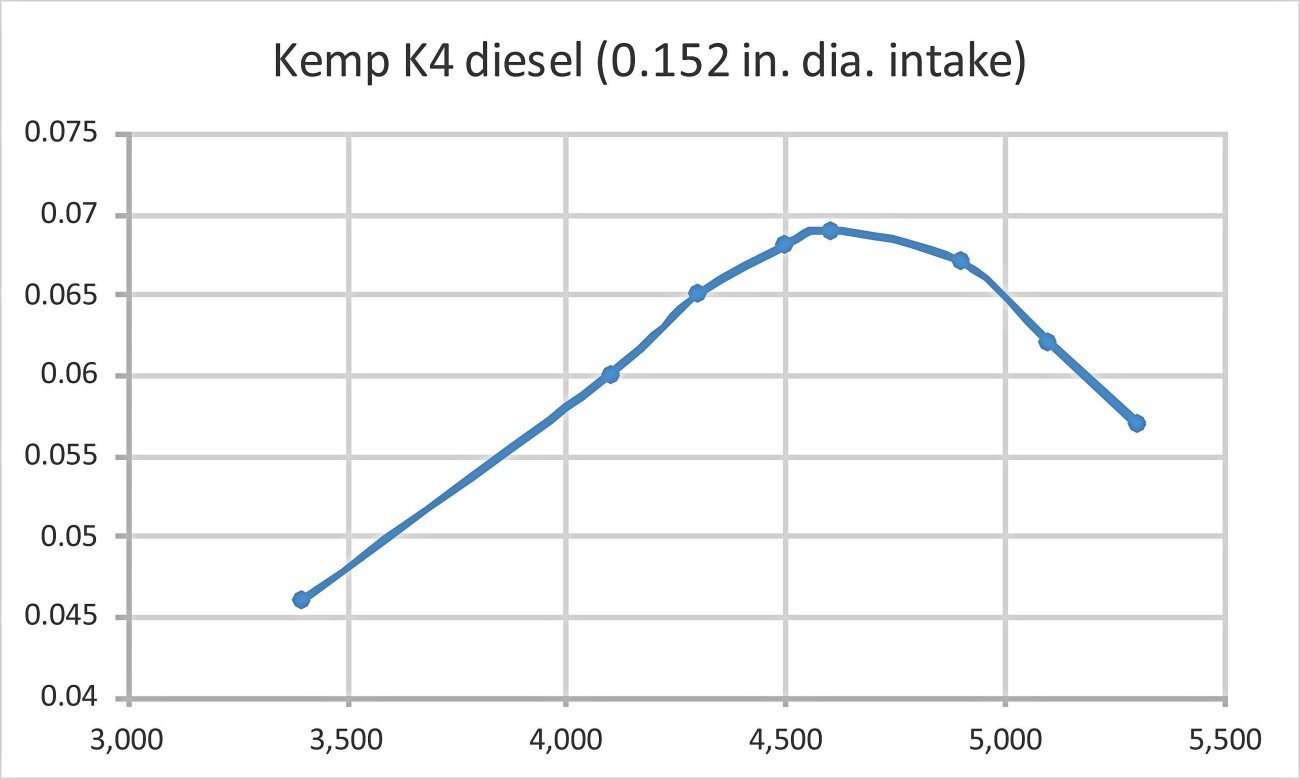
 ignificantly smaller displacement and crankshaft front rotary valve. It appears that while the K4 could now ingest more fuel mixture, much of the extra was going straight out the exhausts without being burned!
 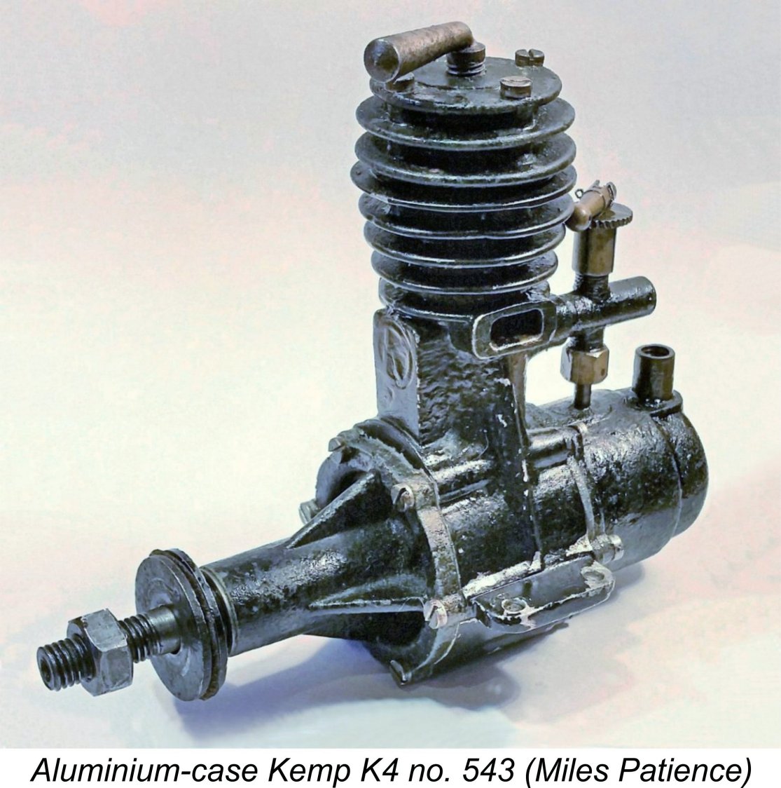 The K4 enjoyed a rather brief production life, and magnesium castings do not weather well, seeking (as Bert Streigler has said) always to return to the sea from whence they came. Quite apart from this, the engine was expensive to produce, resulting in a relatively high price by evolving 1947 standards. Moreover, its power limitations would soon have become frustratingly apparent to owners, particularly those attracted to the growing field of control line flying.
| |