
|
|
An Old Favourite Revisited - the FROG 500
The enduring popularity of the FROG 500 was (and remains) due to a number of very positive attributes with which the engine was endowed. It was produced to a highly acceptable standard, with working components that were generally well designed from an engineering standpoint. These factors ensured both mechanical dependability and a very long working life - it’s quite rare to encounter one even today that is anywhere near worn out unless it has been quite severely abused in some way. In addition, the 500 delivered a level of performance which was well suited to the needs of the stunt and sport fliers of its generation, who far outnumbered those of today. If this wasn’t enough, it was a delightful engine to handle, also possessing an unusual degree of operational flexibility. Finally, it sold for a most competitive price for an engine of its displacement. However, it wasn't all wine and roses - there were pitfalls built into the engine’s design, some of them serious. As always in these articles, I won’t sugar-coat the truth of these issues in any way. By doing this, I hope to encourage the future use of these engines in a manner that recognizes their limitations and thus preserves them for the potential enjoyment of future generations of model engine enthusiasts. When I began to research this story way back in 2012 prior to its original February 2013 publication on the late Ron Chernich’s “Model Engine News” (MEN) website, I was frankly expecting it to be a relatively straightforward exercise centering upon a fairly ordinary engine about which there was little new to be learned. In fact, I undertook it mainly in response to a number of reader requests for more information on this engine to go along with that published earlier for other FROG models. However, I was pleasantly surprised at the unexpectedly high level of interest displayed by a number of my closer colleagues, who backed up their interest by providing serial numbers as well as their own views on the engine along with related anecdotes. As time went on, I also became increasingly amazed at the unfolding complexity of the story, which greatly exceeded my expectations. No matter how much you think you know, there’s always more to be learned!
My other valued Aussie mate Maris Dislers was also most generous in sharing data in his possession along with his personal observations. These did much to inform and expand my own views regarding the engine. I must also acknowledge the invaluable assistance rendered by Eric Offen, who went so far as to drill into a flawed FROG 500 cylinder to confirm the material. Randy Ryan and Brian Cox also provided comments and serial numbers. Finally, without the help of my late good mate Ron Chernich I wouldn’t have got anywhere with this project. Ron was most generous in digging out adverts and test reports as well as sharing his own insights. My sincere thanks to one and all. After the initial publication of this article on MEN in early 2013, I was delighted to hear from none other than Gordon Cornell (now sadly deceased), who worked for FROG manufacturers International Model Aircraft (IMA) from late 1957 through to late 1958. Gordon was kind enough to add a number of details which did much to inform my understanding of the FROG 500. The general merit of the FROG 500 in the context of its times was no doubt due in large part to the fact that its manufacturers already had a wealth of model engine development and manufacturing experience at the time when the 500 was designed. Let’s take a quick look at the history of the company up to that point. I’ve covered this story in more detail in a separate article to be found elsewhere on this website. Those already familiar with this part of the tale are invited to skip to the following section …………….. Background
In passing, it's worth restating for the record that the name of this famous range is correctly rendered in block capitals as "FROG", not "Frog" as all too often used. This is because it's an acronym containing the first letters of the company's four-word motto. IMA themselves always rendered the FROG name in block capitals both in their promotional material and on the engines themselves. A FROG is a model engine - a Frog is an amphibian!
Sadly, John Wilmot perished in a motor vehicle accident in 1943. In 1944 Charles Wilmot and Joe Mansour were forced to sever their connection The enforced departure of the two surviving IMA founders was widely viewed as a matter for regret by those who remained behind - indeed, several of these individuals showed their views very clearly by subsequently leaving IMA to join Wilmot and Mansour in their ongoing activities. Following the conclusion of the war, the two re-commenced trading under the Wilmot, Mansour name, going on to develop and market the famous Jetex series of compact solid fuel model jet engines and associated kits. The end of WW2 triggered a general desire for a rapid return to normalcy. Lines Brothers quickly resumed their former activities, marketing a wide variety of toy and model products through their various subsidiaries, of which IMA was only one among others. The bulk of the parent company’s early post-war manufacturing for all their brands was concentrated at their very large factory located on a 27 acre site on Morden Road (today’s A24) in the south-west London suburb of Merton in Surrey. The exact location is on the east side of Morden Road just to the south of its junction with today’s Merantum Way and a little north of Morden Road station. The area has now been completely re-developed - no traces of the earlier Lines Brothers facilities now remain.
Although large by British model industry standards, IMA’s 113,600 square foot production facilities represented only a modest portion of this giant complex. The large playing field seen towards the right in the attached image formed part of the complex, being put to good use by IMA as a test area for new flying model designs. As a result of the importance of their wartime work making military hardware, Lines Brothers had enjoyed a high level of government support in terms of keeping their plant and equipment up to date and in good condition throughout the conflict. The factory had been damaged by enemy action during the war, but was quickly refurbished. Consequently, the company entered the post-war period with an intact factory, a large experienced workforce and plenty of good quality machine tools on hand - no need to go scrounging for clapped-out wartime surplus equipment at fire-sale prices like so many others.
The first model engine design produced by IMA under Judge’s direction was the FROG 175, a 1.75 cc spark ignition motor which appeared in early 1946. This competitively-priced unit was one of the first new commercial model engine designs to appear on the British market in the post-war period. It was soon followed by IMA’s first diesel, the FROG 100, which first appeared in pre-production form in late 1946 and reached the market in quantity in mid 1947. Both of these engines were based upon freelance designs by the well-known aeromodeller and model engineer George Court (1899 - 1960). I’ve included a capsule biography of George Court in my companion article on the early FROG models. My good friend Miles Patience has also However, Bert Judge was ultimately responsible for the final design of both engines, as he was to be for the entire FROG model engine range through to 1951, when he left IMA to join Wilmot and Mansour in their very successful Jetex venture. Judge’s final engine design for IMA was the Mk. I version of the FROG 50, which appeared in early 1952. From late 1946 onwards, diesels quickly took over from spark ignition engines as the preferred choice of modellers in Britain and the rest of Europe. IMA themselves added to their model diesel range in June 1948 with the appearance of the FROG 180 diesel, essentially an overbored version of the second-generation FROG 100. Even the Americans took a hand in the compression ignition game with a number of excellent model diesel designs of their own. Articles covering many of these American designs may be found elsewhere on this website. Late 1947 - the FROG 500 is Conceived
During the visit, Bob told David and Gordon that he had been in charge of the production side of IMA’s model engine program (including the FROG 500) during the late 1940’s, continuing until mid 1951. Jon Fletcher has advised that he too was acquainted with Bob Bright, thus having received the same information independently. As a result of Bob Bright’s former position with IMA, he had a wealth of first-hand knowledge regarding IMA’s model engine production activities at this time. Among other things, he still possessed a number of IMA factory drawings of some of the FROG model engine range. David took copies of these drawings, several of which were related to the FROG 500. Although they are now too faint for legible reproduction here, it has been possible to extract some highly relevant information from them. We owe David a debt of gratitude for taking the trouble to do this. These drawings confirm Bert Judge as the designer of the FROG 500 - his initials AAJ appear on the drawings relating to that model. This comes as no real surprise - the real eye-opener is the fact that drawing no. 500/1 (the FROG 500 crankcase) is dated 26/3/48! The drawing number seems to prove that this was the first drawing produced, while the date proves that Bert Judge was already hard at work on the design of the FROG 500 in early 1948, almost a full two years prior to the engine’s actual appearance in the marketplace! The drawing also provides evidence of an amendment dated 21/2/50 involving an increase in the external radius of the two bolt pads inside the exhaust duct, apparently to clean up a damaged die. OK, so Bert Judge was well stuck into the design of the 500 as of early 1948. What happened?!? Why was the actual release of the engine so long delayed? Although it can’t be proved, by far the most logical supposition is that the design was commenced as a spark ignition model but was temporarily shelved upon The miniature glow-plug was an American development for which most of the credit must go to the brilliant American model engineer Ray Arden (1890 - c. 1953). The commercial advent of the miniature glow-plug in the USA during late 1947 soon diverted the vast majority of US modellers away from both spark ignition motors and diesels towards the new form of ignition. Word of this then-revolutionary technology quickly spread to England, the consequence being that by mid 1948 increasing attention was being paid to the potential of the glow-plug motor by both modellers and manufacturers in Britain.
This in turn prompted a number of British accessory manufacturers to commence the production of miniature glow-plugs for model engines. The most notable of these was the firm of Smith’s Motor Accessories Ltd., who found it worthwhile in mid 1948 to have their subsidiary K.L.G. Sparking Plugs Ltd. begin production of the famous Arden-influenced ball-headed “Miniglow” plugs in various sizes.
Could the manufacturers of the FROG range remain aloof from this?? Not at all!! In particular, they evidently began to question the wisdom of continuing the development of an all-new 5 cc spark ignition design pending further testing of the market for glow-plug ignition in Britain.
It was not until later in 1948 that purpose-built commercial glow-plug engine designs began to appear in the USA. Hence the option of copying an established glow-plug model was not open to IMA as of early 1948. This left them with two potential pathways to entry into this new market - innovate or convert. The first of these two options involved the development of an all-new design from scratch. While this approach doubtless offered the greatest potential, it was by far the most expensive option of the two. It was also problematic insofar as British designers at this early stage had little if any experience with the new ignition technology. At first sight, it would appear that IMA could have pursued a modified form of the innovation approach by simply switching their still-evolving 500 design from spark to glow-plug ignition, as indeed they were to do over a year later. The fact that they chose not to go this route at this early stage implies that their investment in the new model remained relatively small at the time. It would appear that they had not yet got as far as actually producing any of the major tooling or components for that design. If they had done so, surely they would have adopted this approach in order to realise upon their investment? As matters stood, the 1948 introduction of a glow-plug version of their as-yet incomplete 500 design would have involved the amendment of the design to glow-plug format together with the creation of the necessary dies as well as the complete tooling-up of the production line for the new model. All of this would have required a significant additional investment. At this stage, the response of the British market to glow-plug ignition was evidently seen as too uncertain to justify such an outlay. Better perhaps to hedge their bets - at least, that’s how IMA appears to have seen it. In any event, there was no need to produce an all-new model to test the glow-plug market - the conversion option was readily available to IMA, albeit in a very different displacement category. This approach involved the relatively simple process of producing a glow-plug conversion of an established diesel or spark ignition design, just as E.D. had chosen to do with their then-new Mk. III diesel model. This would side-step the bulk of the development and tooling-up costs very nicely since most of the components would already be in production. However, it would probably fall short of producing the optimum results - in particular, the simple switch from diesel to glow-plug ignition rarely resulted in the best-possible performer.
So the next step in the evolution of the FROG model engine range was the temporary shelving of the FROG 500 project pending a test of the British glow-plug market through the mid 1948 replacement of the 175 spark ignition model with the 160 glow-plug version of the basic FROG “bicycle spoke” design. In effect, the 160 was nothing more than a slightly under-bored 175 model without the timer. It joined the established 100 diesel and its newly-introduced companion, the FROG 180 diesel, as the third member of the then-current FROG model engine range. The fact that the 160 shared the castings and lower end components of its contemporary relatives must have done much to reduce development and production costs. It proved to be the first of a number of glow-plug models to be marketed under the FROG name. Based on Lawrence H. Sparey’s published test of the FROG 160 (“Aeromodeller”, August 1949), the engine’s measured power output of 0.083 BHP @ 10,850 rpm was very little greater than that obtained a year later from the FROG 100 diesel. But the power was greater………. and the engine was lighter and more compact as well despite its greater displacement. It only weighted 3¼ ounces – a saving of half an ounce over the 100 diesel and three-quarters of an ounce over the 180.
IMA helped the cause greatly in June 1948 by releasing their Vandiver control line stunt model kit specially designed by J. R Vanderbeek for the FROG 100 and 160. This kit was very popular, being built in large numbers by enthusiastic owners of FROG engines. Many of these were powered by the FROG 160 glow-plug motor, using which they performed very well. IMA must have been encouraged by the results of the 160 glow program, because in mid 1949 they resumed the development of the 500 with one major change - a switch to glow-plug ignition. This time, IMA stayed the course and carried the project through to completion. Late 1949 - the FROG 500 Takes Shape
Given the design supremacy enjoyed by US manufacturers at this point in time, any British producer who wished to challenge them was more or less forced to follow in their footsteps. A number of British firms such as Nordec, Ten-Sixty-Six, Rowell and ETA had already developed American-influenced racing models to (unsuccessfully) challenge the leading American designs, although most of these efforts had been in the rather specialized 10 cc racing class. In the sport category, matters were less clear-cut. Doubtless attracted by the novelty factor, British modellers had engaged in an early period of experimentation with glow-plug engines in non-racing applications - the FROG 160 and Yulon 30 were major players in this regard. However, as time went by the amount of attention paid by British modellers to glow-plug engines waned considerably, particularly in the lower and middle displacement categories. In those categories, the ever-evolving diesel models tended to outperform the glow-plug opposition, at least in non-racing applications. Accordingly, the diesel was well on its way towards achieving the pre-eminence which it was to retain in Britain for the better part of the next three decades.
By contrast, American-style glow-plug engines in this displacement category tended to be both lighter and far easier to handle than their European diesel counterparts while also offering a higher level of performance. It’s likely that IMA’s decision to enter the 5 cc market with an American-influenced glow-plug design was based upon a shrewd appreciation of this factor. ETA had already taken this pathway into the 5 cc racing market with their ETA 29 model, and now IMA planned to follow suit, albeit with a design intended for general-purpose use rather than all-out racing.
Experience in America beginning in early 1948 had shown that the loop-scavenged 5 cc crankshaft front rotary valve (FRV) glow-plug motor was ideally suited to the demands of the control-line stunt category which was rapidly becoming one of the most popular competition classes in Britain. It had also proved to be ideal for R/C applications. If a domestically-manufactured general-purpose 5 cc glow-plug motor meeting American performance and quality standards could be introduced to the British market, it would doubtless achieve great popularity. This would be particularly true if it could be sold at a competitive price.
In particular, the publication of a review of the Torpedo 29 (complete with superb cut-away drawing by the very talented Lee Scott) in the January 1948 issue of “Air Trails” magazine may well have informed Judge's design decisions to a significant extent. It’s by no means impossible that he might even have acquired an actual example through contacts in America. After all, he had won the 1936 Wakefield Trophy at a meet held at Detroit, Michigan and doubtless retained some of the contacts that he had made there. The K&B Torpedo 29 spark ignition model which was in production at the time in question was a development of the original K&B Torpedo “B” model which had been the first design introduced by the K&B Manufacturing Co. of Bell Gardens, California following their acquisition of rights to the Torpedo name from Bill Atwood. It’s unclear whether or not IMA approached K&B for permission to draw upon this design, but it seems to me to be highly unlikely that they did so - certainly, we have no evidence whatsoever to suggest that such an approach took place. It seems far more likely that Bert Judge simply used the general layout of the Torpedo as the inspiration for his new design, relying on the relatively low probability of K&B’s taking an interest in the FROG product in the first place while also making enough architectural and functional design changes that IMA would stand an excellent chance of defending themselves against any charges of direct plagiarism in the unlikely event of such a situation arising. It seems that IMA’s reliance upon these considerations was well founded. Knowledgeable British commentators of the period were not fooled - they frequently referred to the fact that the FROG 500 was based upon an American prototype, occasionally even going so far as to name the K&B Torpedo 29 as the model in question. However, IMA were never openly criticised on that score, nor do K&B ever appear to have taken a hand in the game. If we are to be honest, almost all model engine designs draw heavily from those of their predecessors.
Another often-overlooked difference was that unlike the sparker, the Glo-Torp 29 was always sold without a tank. This clearly reflected the manufacturer’s very logical belief that many of the engine’s purchasers would use it in free flight or control line applications, for both of which purposes a separate tank would generally be used. Examples of the Glo-Torp periodically appear today on eBay and elsewhere with tanks, but these have been added by over-enthusiastic collectors in the mistaken belief that they are returning the engine to its original form. Don’t pay a premium price for one of these engines solely on the basis that it has a tank - if you want to be original, the first thing that you have to do is remove the tank!!
If it was good enough for K&B, it was certainly good enough for IMA! The reported success of the conversion of the K&B 29 to glow-plug ignition doubtless encouraged IMA to follow K&B’s lead by tasking Bert Judge with switching their Torpedo 29-based FROG 500 design from spark to glow-plug ignition. Whatever the circumstances, the end result of Judge's consideration of the main design features of K&B’s very successful product was the late 1949 introduction of the FROG 500 glow-plug model which forms our central subject.
If any cases for the spark ignition FROG 500 had been manufactured in 1948 prior to the temporary shelving of the project, IMA would surely have used a few of those cases in their prototype glow-plug models?!? The machining of the main bearing to accommodate a timer would not have precluded this. The fact that they seemingly did not do so clearly implies that no such cases existed. It would appear that the creation of the necessary dies and the manufacture of the die-cast components post-dated the testing of the sandcast glow-plug prototypes, presumably in mid to late 1949.
It's certainly true that to meet the editorial deadline for the March issue (which actually appeared in mid-February), the advertisement would have had to have been prepared and submitted by late January. This in turn clearly implies that the engine must have been in existence by that time. Chinn’s dating on British engines was generally pretty reliable given his position as one of the most highly respected model engine commentators of his day as well as the fact that he was recording events which were then very recent. In addition, the release of this particular engine had clearly made a strong impression upon him. His comments thus suggest the hitherto unproven possibility that the 500 was actually released in time for Christmas 1949 (an entirely logical objective) in advance of the preparation of a national advertising campaign relating to the engine. Perhaps IMA wanted to quietly test user reaction to their new offering through an unadvertised London-area dealer release. In an early 2013 communication with me following the initial publication of this article on MEN, the late Gordon Cornell was kind enough to set this matter straight. He was able to confirm that the FROG 500 was indeed available in the London area in late 1949. His friend Clive Heaseman purchased one in December 1949, having saved up the purchase price of £3 15s 0d (£3.75) from the proceeds of a paper round - he was 13 years old at the time. Having resolved this apparent anomaly in the record, let’s have a close look at this classic design. The FROG 500 - First Model
Bore and stroke were 0.750 in. (19.05 mm) and 0.680 in. (17.27 mm) respectively for a displacement of 0.300 cuin. (4.92 cc). Interestingly enough, this placed the engine fractionally over the American Class B displacement limit of 0.299 cuin. (4.89 cc), implying that IMA had no plans at this stage to export the 500 to America. The engine did however comfortably respect the British Class B limit of 4.99 cc, which was presumably the priority.
I’ll begin by listing the similarities between the FROG 500 and the K&B Glo-Torp. Both the FROG and K&B models were based upon a cleanly-formed pressure die-cast crankcase which incorporated the exhaust stack, intake venturi and main bearing housing in unit, along with relatively thin mounting lugs of identical design located well above the engine’s thrust line. Both featured a lapped cast iron baffle piston running in a heat-treated steel cylinder having integrally-formed cooling fins and being topped by a finned die-cast alloy cylinder head. The cylinder assembly in both cases was secured in place by four long machine screws (4-40 in the K&B and 6BA in the case of the FROG). Both models also featured a forged aluminium alloy con-rod driving a one-piece steel crankshaft which ran in a bronze-bushed main bearing. A brass retaining stud was used in both cases to keep the con-rod on the centrally-drilled crankpin and prevent it from rubbing on the backplate.
These features must surely be familiar to anyone having an interest in model engines of the era in question. This being the case, there seems to be little need to describe the FROG in greater detail in this article. What does seem relevant here is to list the departures from the design of the K&B Glo-Torp 29 which evidently inspired the design of the FROG 500. As it turns out, the somewhat different external appearance of the two engines obscures the fact that these departures were relatively inconsequential for the most part. Perhaps it was intended to do so! One potentially significant change which was not obvious through external examination was the internal geometry. We saw earlier that the FROG 500 featured over-square bore and stroke dimensions of 0.750 in. (19.05 mm) and 0.680 in. (17.27 mm) respectively for a displacement of 0.300 cuin. (4.92 cc). By contrast, the K&B employed square measurements of 0.725 in. (18.41 mm) and 0.724 in. (18.39 mm) respectively for a displacement of 0.299 cuin. (4.90 cc). The K&B thus precisely complied with the US Class B rules, while the FROG technically did not. We might also expect the K&B to produce a bit more torque than the FROG thanks to its longer stroke.
The next obvious departure was the cylinder head design. The FROG head was a considerably more massively-finned affair, although this had essentially no performance implications. It has to be admitted that the K&B design appears somewhat retrograde in that it placed the point of ignition well away from the isolated “pocket” of mixture trapped behind the piston baffle at top dead centre. The central location of the FROG plug slightly reduced the flame propagation distance to initiate the involvement of this portion of the charge in the combustion process. Accordingly, the FROG may actually have possessed marginally superior ignition characteristics, although in hindsight we can see that neither design was exactly a model of efficiency! It appears that at this stage neither the K&B nor the IMA designers appreciated the importance of turbulence in promoting improved combustion characteristics based upon point source ignition - certainly, IMA’s earlier FROG 175 spark ignition and FROG 160 glow-plug designs reflected no such understanding. It’s also true to say that the importance of this factor decreases at the low and moderate speeds at which both the K&B and the FROG were designed to operate. One potentially significant difference in functional terms is to be found in the configuration of the crankshaft induction port. Both models featured drilled induction ports in their crankshaft journals, but that of the K&B was then milled transversely to give it more of a square shape as presented to the base of the venturi tube. This resulted in more rapid opening and closing of the induction system at the cost of creating potential stress concentrations at the edges of the milled opening. The FROG crankshaft did not feature this milling step, leaving a plain round hole to serve as the crankshaft induction port. We might expect the K&B design to result in slightly more efficient induction, while the FROG design would logically be somewhat more durable in service.
At first sight it might appear that rather than representing a design change, this could actually have been related to a material supply issue of the kind that IMA are known to have experienced from time to time. However, in his published test of the FROG 500 which appeared in the 1950 edition of the British periodical “Model Aviation” (see below), Peter Chinn stated that this change was actually prompted by the tendency of the cast iron bushing to seize when running light with inadequate cooling, conditions often encountered in model boat and car operation as well as cowled aircraft service.
The differences discussed above were mainly matters of architectural detail - in broader terms the two engines were very similar indeed. It would have been useless for IMA to deny the influence of the K&B upon the FROG 500 design, and indeed they never did so
The initial variant of the FROG 500 just described featured relatively thin and somewhat flimsy mounting lugs, another feature which it shared with the K&B. It is accordingly often referred to as the “thin-lug” model. I’ll use this terminology throughout the balance of this article. Interestingly enough, there appear to have been at least two distinct crankcase dies in concurrent use more or less from the outset. One die maintained the open finning of the upper crankcase at front and rear between the stack and the expansions for the transfer-side cylinder installation screws. The other die formed a casting in which the top cooling groove just below the casting’s upper surface at front and rear was filled in. The groove remained open on the transfer side opposite the stack. The difference had no functional effect. My own engine number 10953 is the earliest example of my present acquaintance which displays the filled-in groove. The goal of the filled-in design was presumably to increase the stiffness of the casting’s upper surface, thereby improving its resistance to distortion arising from cylinder installation forces. This must have proved effective, because at around engine number 16000 the filled-in upper groove seems to have became universal, with the alternative die either being modified or retired. Design Issues with the FROG 500
Firstly, while the flexible spring-mounted needle valve extension was undeniably helpful in keeping the fingers well clear of the prop, it had a serious downside in that if the arm escaped from its retaining clip during operation it would inevitably spring forwards into the spinning prop disc, damaging both itself and the prop. This probably explains why relatively few well-used examples encountered today retain their spring extensions. If the extension needle was to be employed, it was wise to use a pair of clips with their slots running in opposing directions, also ensuring that their retaining nut remained fully tightened.
Another feature that was more of a design anomaly than a real fault was the chosen combination of venturi choke area and spraybar diameter. The engine was provided with a very generous venturi throat diameter of 9/32 in. (7.14 mm) at the location of the 1/8 in. (3.17 mm) dia. spraybar. This was fine for bench running as well as for level control line or free flight applications where fuel head changes were not an issue. However, it proved to be less than ideal for control line stunt use - rather odd considering the fact that this was the engine’s most logical application!
Fortunately, the fix is simple - either replace the standard spraybar with one having a diameter of 5/32 in. or insert a balsa-wood intake restrictor wedge. Even better, make up a 6 mm I/D tubular restrictor to fit the venturi, as I did. This reduces the minimum operating speed on suction in an aerobatic application to 11,200 rpm - an ideal speed at which to operate this engine in the air. So equipped, the 500 was (and is!) an excellent classic stunt motor, with many competition successes to its credit. If one elected to go the spraybar replacement route, it would be wise to take advantage of the attendant opportunity to improve the needle valve design itself. The original needle valve used the not-uncommon but highly suspect arrangement whereby the needle taper metered the fuel supply at the fuel delivery jet hole rather than by engaging with a concentric seat inside the spraybar itself. This arrangement is prone to a serious level of inconsistency arising from such factors as sloppy needle fit, off-centre needle taper, thread wear, etc. Best modified for consistent performance ............. Although this is again more of a characteristic than a fault per se, the fact that the cylinder was made of mild steel which was case-hardened to the point of brittleness resulted in the cooling fins being easily broken if undue force was applied, for example when removing a well glued-on cylinder head. This explains the examples of the FROG 500 that are not infrequently encountered today with broken cylinder fins. There appears to The cylinders were evidently not alone in exhibiting symptoms of inconsistent heat treatment - the crankshafts also apparently suffered from the effects of this issue. Evidence for this is found in the fact that a rash of crankshaft breakages in Australia actually prompted the Myers Emporium of Melbourne (a major FROG dealer in that country) to contract with the late Gordon Burford for the production of a batch of replacement crankshafts for the FROG 500. In fairness to IMA, it must be admitted that this issue appears to have been essentially confined to one specific batch of shafts, since most of those in use worldwide survived well and continue to do so over 60 years later. It's also very likely that this issue could not be directly attributed to IMA, since the heat treatment process was almost certainly contracted out, like many aspects of FROG model engine manufacture. In more than 50 years of using FROG 500’s, I’ve never managed to break one myself.
All of this having been said, there’s no doubt that if the owner treated his engine well by not taking it apart unnecessarily; keeping it clean; keeping it out of the ground; using appropriate tools and techniques if servicing did become necessary; running the engine on good fuel having adequate lubricating qualities; and using a correctly-matched airscrew, the majority of them would perform well and seemingly run forever. Moreover, the 500 was one of the nicest-handling mid-sized glow-plug motors ever offered to the British public. If properly set up with the correct spraybar-venturi combination, it was particularly well-suited to control-line stunt applications due to its excellent break between two and four-stroking allied to outstanding suction. I’ve certainly enjoyed flying my own examples! The FROG 500 on Test Given the fact that the FROG 500 was the first American-style 5 cc stunt motor to be released in Britain, it filled a major gap in the British model engine market, hence creating quite a stir when it first appeared in late 1949. A particular attraction was its remarkably low selling price of only £3 15s 0d (£3.75), which represented outstanding value for an engine of this displacement. Peter Chinn was later to recall that in a small model club of his personal acquaintance, over two-thirds of the membership bought FROG 500’s within the first few weeks of the engine’s availability. No doubt this scenario was widely repeated throughout the country. Given Chinn’s experience recounted above, it was only natural that he should have placed the FROG 500 high on the list of candidates for a published test in “Model Aircraft”. However, he was no keener than Lawrence H. Sparey of the competing “Aeromodeller” magazine. Both testers were quick to get examples of the new model onto their benches, with reports by both individuals appearing in the May 1950 issues of their respective magazines. Beginning with Sparey’s report in the May 1950 issue of “Aeromodeller”, there’s no doubt that old Lawrence was thoroughly impressed with the FROG 500. He praised the engine’s starting and running characteristics very highly, stating that this was typical of the FROG engines which he had handled up to that point. Somewhat unusually, he actually found a slightly higher level of performance than Peter Chinn, reporting an output of 0.381 BHP @ 13,200 rpm using FROG “Red Glow” fuel, which was essentially a straight methanol/castor blend. Sparey characterised this performance as “extremely good”. Peter Chinn’s report which appeared in the same month’s issue of “Model Aircraft” was just as positive. Although the MA test series was unattributed at this stage, no evidence has ever been presented to suggest that the author of the series was anyone other than Peter Chinn. Not surprisingly, the findings of these two reports were essentially identical. An output of 0.37 BHP @ 12,000 rpm on straight methanol/castor fuel was reported in both cases, this being considered a very good “sports” performance by the standards of the day. Starting and running characteristics received very favorable comment as well. The engine was understandably viewed by Chinn as representing excellent value for money. Incidentally, Chinn was subsequently to report that outputs as high as 0.45 BHP @ 13,000 rpm were recorded using fuels with a significant nitromethane content - a perfectly credible claim. Taken together, these three published tests were certainly about as positive an endorsement of the new model as IMA could have wished for. Although the “FROG Super-Powered” transfer provided with each engine overstated the case somewhat, the fact remains that the reported performance was well up to most modellers’ expectations as of early 1950. Estimated production figures based upon reported serial numbers make it abundantly clear that the initial reception accorded to the FROG 500 by the British modelling public was extremely encouraging in sales terms. Let’s look at the serial number issue next. Serial Numbers and Production Issues
Earlier examples frequently (but not invariably) displayed the number on the outer ends of the mounting lugs, while later products from around 16000 onwards were always numbered on the case below the lugs. More significantly, all of the numbers for the original thin-lug model reported from various sources during the research stage of this study are evenly distributed within the 10000 to 20000 range. The statistically-reliable size of my quite large sample leaves no room for doubt that the sequence started at 10000 and went on up from there without a break to around 20000. At present, the highest serial number of my acquaintance for an example of this model appears on engine number 20000 which remained in the possession of Bob Bright at the time of the previously-mentioned visit paid to him by David Owen and Gordon Burford in the year 2000. At first sight, it seems a little odd to discover that IMA started the numbering sequence for the FROG 500 at 10000 - their previous practise had always been to start the sequence at 1 (or perhaps 100) and carry on from there. Indeed, they continued this practise with their later engines from the 1950’s and beyond - the FROG 500 was the sole exception. There must surely have been a reason for this, and the best explanation that I can think of is that they were deliberately leaving room for the subsequent introduction of the originally-planned spark ignition model if market conditions appeared to warrant this at any time. In the event, this provision proved to be well justified, since IMA did subsequently elect to put the spark ignition model into production, as we shall see in the following section of this article. When they did so, they returned to their standard numbering system by starting the sequence at 1 (or perhaps 100), for which space had been left through the starting of the glow-plug version at 10000. The only departure was the addition of the two-letter prefix PE (for petrol engine) to designate those examples as spark ignition models. More of this in its place below………. It seems to be a legitimate conclusion from the reported range of serial numbers that some 10,000 or so examples of the original thin-lug glow-plug variant were made in total. Thanks to the invaluable help of the individuals named earlier, it‘s possible to form a clear picture of production rates for this engine. We noted that Bob Bright was in possession of engine number 20000 of the thin-lug series. Bob claimed that he had taken this engine along with him when he left IMA suddenly in mid 1951, confirming the existence of this example as of that date. Moreover, since no higher numbers have been reported, it must have been one of the last thin-lug models produced.
Bob Bright was able to provide David Owen with some interesting details regarding IMA’s model engine production program at the time of the FROG 500’s introduction. For one thing, IMA apparently relied to a significant extent upon outside contractors for the supply of many of their engine components. In common with other firms which took this approach, this left them exposed to periodic problems with continuity of supply. Bob recalled that the completion of specific batches of FROG engines was often delayed as a result. Two models which are known to have suffered greatly from this cause were the original FROG 175 and FROG 100 offerings - IMA actually made apologetic reference to supply problems in several advertisements in late 1946, including the attached example from October 1946. Bob stated that the engine castings for all models were produced by the long-defunct London Die-Casting Co. Interestingly, this company made the dies from Bert Judge's drawings and retained ownership of the finished dies, contracting with IMA for the supply of the requisite monthly batches of castings, with payment due upon delivery. Thus IMA never owned the dies for their own engines, at least at this stage. Bob claimed that a figure of 1000 sets of castings monthly was agreed for the 500, but this figure cannot be reconciled with the apparent production of only 10,000 examples over an 18 to 20 month period. It seems likely that Bob meant to say that the FROG 500 castings were supplied as required in batches of 1000. Since each example of the engine required the production of four castings (crankcase, cylinder head, backplate, tank), each batch of castings would have included 4,000 pieces! London Die-Casting evidently did not generate the delivery irregularities displayed by some of IMA’s other suppliers - indeed, Bob recalled that the IMA loading dock at Morden Road was not infrequently overwhelmed by shipments of engine castings! By his own account, Bob Bright left IMA suddenly in mid 1951. He recalled leaving work one Friday afternoon, seemingly after a really bad day at the office since he called at Australia House on the way home, having decided there and then to emigrate. He was on a boat to Australia within a week! Under circumstances which must forever remain obscure, Bob took with him a number of FROG engine components and engineering drawings along with the previously-mentioned FROG 500 number 20000. It was all a very long time ago, and all concerned have now passed on ………
Returning to our main thread, the serial number data presented above initially gave rise to considerable difficulty in understanding the production pattern for the FROG 500. In the past it has generally been assumed that the subsequent thick-lug version of the engine was introduced in mid 1955, when the changes to the case to allow the fitting of a ball thrust race were announced (see below). This was impossible to reconcile with the reported range of serial numbers for the engine, since the following thick-lug version carried serial numbers which continued the established serial number sequence on upwards without a break from 20000. This implied that production was suspended for a three-and-a-half year period prior to the appearance of the revised model supposedly in mid 1955, a deduction which made no sense at all. However, it turns out that there is actually no difficulty. What was missing was the recognition of a previously-overlooked interim variant. I’ll get to that in a subsequent section of this article. But first, I have to continue the story from mid 1951 onwards by discussing perhaps IMA’s most surprising new model ever - the FROG 500 PE petrol engine. The FROG 500 PE Petrol Engine
Viewed from a present-day perspective, this looks like a major step backwards in technological terms. Even in the eyes of many contemporaries, the spark ignition motor had died during 1948! To understand IMA's action in launching the FROG 500 sparkie in 1951, we need to go back and review the matter in a 1951 context. As we saw previously, the miniature glow-plug made its initial market appearance in America in late 1947, with word of the new technology quickly spreading to Britain. Like any new technology, its adoption was neither immediate nor universal - many modellers liked the flexibility of the spark ignition motor due to the very precise control of ignition timing which it allowed - a degree of operational flexibility which it shared with its variable-compression diesel compatriots. Moreover, until the use of nitromethane in glow-plug fuels became widespread beginning in 1949, the glow-plug motor did not enjoy any marked performance advantage over its spark ignition competition. What all of this meant was that as British aeromodelling moved into the early 1950’s, there were many active participants who had been regular spark-ignition users until only a year or two previously. Moreover, a sizeable percentage of these individuals retained fond memories of the undeniable operational merits of the former technology. Indeed, there were not a few who continued by choice to use the spark ignition engines with which they were comfortably familiar, particularly for non-competition purposes. In particular, the flexibility of the spark ignition engine in terms of its operating speed range was seen as an advantage by a number of radio control fliers, a sizeable number of whom continued at this time to remain loyal to the older technology.
Although we don’t know exactly what prompted IMA’s decision, it’s a very clear inference that they were somehow made aware of some level of pent-up demand for a spark-ignition version of their 500 model which had evidently been selling well in glow-plug form for some 18 months by this time. Customer feedback may have played a role here, as may the successful results of a few home retro-conversions which are known to have been undertaken by skilled individuals.
Moreover, all of the major components for the revised model were already in production. The only manufacturing changes required to introduce the new model were the very simple re-machining of a batch of standard cases to accommodate the timer; the addition of a cam to the front main journals of a batch of standard shafts; and the manufacture of the timer itself. Everything else was already in production. Hence the manufacture of the spark ignition FROG 500 involved nothing more than dusting-off the already-existing drawings and adding the spark ignition components to the existing production program. Thus the introduction of the new model was far from being a case of reverse-engineering of an existing glow-plug model as has hitherto been generally believed - rather, it was nothing more than the bringing into production of a model for which the design had already been largely completed some three years previously. Put another way, this was in fact the long-delayed release of the original version of the FROG 500, well over three years after its inception! If the engine had been released as initially planned in 1948, this is what it would have looked like.
The new variant was to all intents and purposes identical to its glow-plug companion apart from the addition of a timer and the replacement of the short-reach Miniglow plug with a K.L.G. MINI 2 spark plug. It used the same crankcase and main working components, the only difference being that the front of the main bearing housing was extensively machined to accommodate the timer. This machining included the complete exposure of the bronze main bearing sleeve at the front as well as the creation of a 360 degree annular groove just aft of this exposure to accommodate the timer arm. A rectangular opening was milled into the exposed main bearing sleeve to allow the moving point follower to access the cam which was machined directly into the front of the crankshaft journal. The timer itself was of considerable interest. Since spark ignition engines had a long history of successful operation by the time the 500 PE was introduced, IMA had a wide variety of previous timer designs to examine, along with associated A close look at the attached image should make the main features of the FROG timer clear enough. The moving point was quite conventional, being tensioned by a flat steel shim spring which both held it in place on its pivot bearing and forced it to close when released by the cam. Tension could be adjusted to a degree through the use of shims of differing lengths or even multiple shims. The fixed point was mounted internally in a threaded brass plate which was itself enclosed in a cradle of insulating material extending through the die-cast timer housing. The outer end of the fixed point shaft was slotted for a screwdriver to allow easy adjustment of the gap. Once the gap was set, the point was fixed in place by an external lock-nut. An additional external nut was provided to secure the timer wire. The tensioning of the timer against cam-induced rotation during operation was very neatly and effectively accommodated. A timer arm of flat dural alloy sheet had a crescent-shaped section at one end which engaged with the previously-mentioned 360 degree annular slot machined into the main bearing housing exterior just aft of the timer location. The timer was attached to this arm by two screws which passed freely through clearance holes in the rear of the timer housing to engage with tapped holes in the timer arm. These screws were internally tensioned by coil springs. In effect, this created a spring-loaded “sandwich” featuring a fixed raised lip of the main bearing housing set between the rear surface of the timer housing and the front surface of the timer arm. The latter two surfaces were of course constrained to move as one by the presence of the screws. The amount of friction in the system could easily be adjusted by tightening or releasing the two screws to increase or decrease the spring tension. This in turn controlled the force with which the timer arm and the timer housing pressed against their respective fixed locating surfaces, thus regulating the tension in the timing adjustment system. This arrangement provided very smooth timing adjustment along with complete control over the resistance of the timer to cam-induced rotation during operation. If the timer started to creep while the engine was running, all that was required was to increase spring tension by tightening the two mounting screws a little. Experience shows that this timer worked extremely well.
The relative rarity of this model makes the gathering of a representative sample of serial numbers rather challenging. The presently-reported range for the original thin-lug version of the engine extends from PE124 up to PE638 owned by my friend Peter Scott. This sample includes the number on Lawrence Sparey’s test engine, which appears to be PE533. I’d be most grateful to any reader who is able to extend this range in either direction.
To my mind, the most likely explanation for the existence of this engine (and perhaps a few others like it) is that a few thin-lug PE cases having provision for the timer had been set aside in mid 1951 for use as spares. When they were making the final batch of PE models (almost certainly knowing that they wouldn’t be making any more) they very logically decided to use up those spare thin-lug cases plus any left-over timers. By that time, most PE owners had probably discarded the timer and were using the engines in glow-plug form anyway, so any future case replacements would be met through the use of thick-lug glow cases. At present, all that we can say is that we have firm evidence for the production of only around 650 examples of the original thin-lug PE model, although the actual number may well have been somewhat higher than this. The fact that Lawrence Sparey apparently had engine number PE533 available for test in late 1951 following that June 1951 announcement implies that all of these original thin-lug engines were produced in one or perhaps two batches in mid 1951. Small wonder that this is among the rarest FROG 500 variants today.
A few such engines, including my own example, were restored to original condition thanks to a 2015 initiative by the late and greatly-missed Woody Bartelt to arrange for the production of a small run of very accurate replica FROG 500 timers and tanks. My engine is now restored to completely original and fully functional spark ignition configuration using these components. Woody has now left us, so there won’t be any more. The FROG 500 PE on Test The introduction of a spark ignition version of an established and very successful glow-plug motor was a sufficiently unusual event that it was bound to attract the immediate attention of the model engine testers of the day. First into the fray on this occasion was Peter Chinn, whose test report on the FROG 500 PE appeared in the January 1952 issue of “Model Aircraft”. Chinn began with a justification for the release of the engine, stating his view that it was aimed primarily at the radio control market. He referred to a still-widespread belief that spark ignition remained superior to both diesel and glow-plug engines for R/C work due to its operational flexibility which allowed it to handle larger props than the average glow motor as well as affording a measure of dependable speed control by means of the timer.
Chinn also pointed out that there was nothing to prevent the owner of a spark-ignition FROG 500 from operating it on glow-plug if more power at higher speeds was required. The purchase of a PE model thus provided a wide range of options. Running on a standard petrol/oil mix, Chinn reported a peak output of 0.28 BHP @ 10,900 rpm as depicted in his published power curves which are reproduced here. He expressed his belief that 0.30 BHP @ 11,000 rpm would likely be achieved with a well run-in example. He admitted that this fell well short of the 0.37 BHP @ 12,000 rpm measured on straight methanol-castor fuel with the glow-plug version, but saw that as an academic point given the intended purpose of the spark ignition version. He praised the sparker's starting, running and handling characteristics very highly, commenting in particular upon the flawless performance of the timer. The competing “Aeromodeller” magazine did not lag far behind Chinn in getting to grips with the new model. Lawrence H. Sparey’s test report on the FROG 500 PE made its appearance in the February 1952 issue of “Aeromodeller” only a month after the publication of Chinn’s review.
Sparey’s ongoing loyalty to the spark ignition engine showed through very clearly in this report. He noted that the engine had been introduced “to meet the demands of the many diehard petrol ignition engine fans”, of whom he was clearly one. He praised the engine’s starting and handling characteristics as well as its operational flexibility, noting that the sparker’s very precise control of the ignition timing was “a delight now seldom experienced”. I can personally endorse Sparey’s comments, as documented in my separate article on spark ignition operation. The most notable aspect of this test was the reported power achieved. Using a straight 3:1 mix of pool petrol and mineral oil, Sparey reported an output of 0.420 BHP, somewhat higher than the 0.381 BHP figure that he had reported for the glow-plug model tested earlier, albeit at the same speed of 13,200 rpm. Given Peter Chinn’s inability to get the same model to develop even 0.30 BHP, it’s really hard to understand how Sparey managed this................ In Sparey’s view, it should have come as no surprise “that there should be a demand for such an easy-to-operate and economical power unit”. A ringing endorsement of IMA’s decision to turn back the clock with this model! The FROG 500 - the Previously Unrecognized Second Variant
Chinn stated in that article (reproduced at the right) that he had recently received examples of three members of the “revised 1955 Frog range”, including the 500. He went on to provide a detailed description of the changes, including the thicker lugs and the ball thrust race. Understandably, this led most people (including myself!) to believe that these revisions dated in their entirety from 1955. Indeed, it appears that Chinn himself believed this to be true. This gave rise to the previously-noted difficulties in reconciling the serial number sequence with the logical production and sales patterns for the engine. These difficulties arose mainly from Bob Bright’s statement (from a position of first-hand knowledge) that engine number 20000 of the original thin-lug plain bearing series which remained in his possession in the year 2000 was in existence as of mid 1951. Since my quite large thin-lug sample contained no serial numbers beyond 20000, the inescapable conclusion was that the manufacture of the thin-lug engines ceased around mid 1951. This gave rise to seemingly insurmountable interpretive difficulties given the fact that the thick-lug version continued the serial number sequence without a break from 20000 upwards. If the thick-lug version didn’t appear until mid 1955, we would be forced to believe that production of the FROG 500 ceased altogether for four years pending the release of the updated version with thicker lugs and a ball thrust race, after which production was resumed at a far higher rate than formerly. But how could this be? If production of the FROG 500 was in fact suspended in mid 1951, as the serial numbers appeared to suggest, then it could only have been in response to a sharp drop in demand for the engine. In turn, if that were the case, why would IMA then re-introduce the engine four years later in modified form?? Even more surprising, why in mid 1951 would they introduce a spark ignition version of a glow-plug engine which they were about to remove from their production program?!? None of this made any sense at all!!
Instead, the inner end of the Vandervell sintered bronze bushing which now served as the main bearing sleeve protruded from the casting at the front of the recess just far enough to stand slightly proud of the front wall of the crankcase interior. The inner end of this bushing thus served as the thrust bearing, with the main bearing remaining plain throughout. The downside was the fact that the final 0.100 in. of the Vandervell bushing was unsupported by the case - probably not a serious issue given the stiffness of the bushing. The clincher came when I returned to Peter Chinn’s August 1955 article. Chinn included an image of the new 1955 example of the FROG 500 featuring the ball thrust race which he had then just received from IMA. Fortuitously, this image showed the serial number of the engine very clearly. The number was So how do we make sense out of all of these observations? Well, it seems clear that by mid 1951, when the serial numbers were approaching 20000, IMA must have become aware of the vulnerability of the original thin FROG 500 mounting lugs to crash damage. They therefore decided to revise the crankcase by making the lugs thicker. A further minor change was the elimination of the slight taper in the side profile of the cylinder cooling fins, perhaps for cost reasons. These were now parallel, resulting in a slight overhang of the upper crankcase deck by the cylinder location flange. This was presumably a production-driven amendment - it had no functional significance.
The key point is the recognition that the switch to the thick-lug case came in mid 1951, not mid 1955 as implied by Peter Chinn’s article. Externally, the only visible evidence of the changes was the increased thickness of the mounting lugs. Internally, the only change was the inclusion of the recess in the front wall of the crankcase. Along with this went a change from a machined bronze main bearing bushing to a proprietary sintered bronze Vandervell component. As noted earlier, this continued to perform double duty as both the main and thrust bearings. The result was the hitherto-unrecognized second variant of the FROG 500. This was identical to the earlier version apart from the increased thickness of the mounting lugs, the straight side profile of the cooling fins, the addition of the internal recess to accommodate a future ball thrust race and the switch to a recessed rearward-protruding Vandervell bushing for the main bearing. None of these changes were such as to affect performance in any meaningful way. The thrust bearing recess was not machined out at this stage, being left in its as-cast state. It appears that these modifications were introduced in the second half of 1951 with no fanfare whatsoever. This doubtless explains why Chinn seems to have remained unaware of the interim variant. It was only in mid 1955, when the inclusion of a ball thrust race was finally implemented, that IMA thought it worthwhile to send Chinn an updated example for review, clearly failing to mention that most of the changes had in fact been implemented almost four years earlier!
I noted previously that at least one batch of FROG 500 PE spark ignition models was manufactured using the revised thick-lug crankcase configuration. I've shown that the original thin-lug version of the FROG 500 PE version undoubtedly went up to engine number PE583 and perhaps beyond, which is completely consistent with that variant having been produced in one or perhaps two batches in mid 1951 when the original case was still in use. With the sole reported exception of my own engine number PE1225, FROG 500 PE models having higher serial numbers feature the modified thick-lug case, showing that response to the first batch or batches was sufficient for IMA to elect to make a few more examples following the introduction of the revised crankcase. At present, the lowest serial number that I have for a thick-lug PE model is PE958 while the highest serial number using such a case is engine number PE1017 - far too narrow a range to allow us to draw any firm conclusions regarding production figures. Even so, the thick-lug PE model appears to be the rarest FROG 500 variant of them all.
This being the case, it appears probable that production figures for the FROG 500 PE fell short of reaching the 1,300 mark for both variants combined. Understandably, this makes the PE version by far the rarest FROG 500 variant today, particularly the thick-lug variant. This is especially true of examples which retain their timers, since it would appear that many owners discarded the timers early on in favour of the far more convenient use of glow-plug ignition. Ironically enough, it’s now possible to recognize that in practical terms the thicker mounting lugs applied to the revised model made little difference to the crash-resistance of those features - the increase in strength was far more apparent than real. This was because all of the extra thickness was added to the top surface of the lugs, presumably to maintain the engine’s thrust line relative to the bearers in the model. The lugs themselves were undoubtedly stronger, but that was not the main issue which needed to be addressed. The real problem was the tendency of the lugs to shear off from the case. Such failures were generally initiated through the fracture of the comparatively thin “bridge” of metal above the backplate fastening holes.
Jon Fletcher also pointed out that the presence of the recess at the rear of the main bearing created a significant weakness at the point where the main bearing housing met the front of the crankcase. Although not machined out to its full design dimensions of 0.625 in. dia. x 0.125 in. depth, the as-cast recess still had an O/D of 0.605 in. and a depth of 0.100 in. (measured from my own engine number 24229). Since the measured thickness of the front wall of the same crankcase was only 0.090 in., this recess actually extended by 0.010 in. into the interior of the 0.673 in. O/D main bearing casting. The result of this intrusion was that the main bearing housing had an unsupported radial wall thickness of only 0.034 in. immediately in front of the point where it met the crankcase. Any kind of hard knock could theoretically initiate a fracture at this point, as could operational metal fatigue due to vibration. The original design without the recess was undoubtedly far stronger at this location, particularly given the fact that it was very well supported internally by the main bearing bushing. That having been said, the main bearing housing was very well braced by external gussets. Experience has shown that the thick-lug plain bearing cases are not notably susceptible to failure at this point if treated respectfully. Final Fling - the Third and Final Model of the FROG 500 As of the beginning of 1955, the FROG 500 was entering its sixth year on the market. Production figures had tapered off significantly, but a steady albeit modest ongoing demand for the engine seemingly remained which was at least sufficient to keep it in IMA’s production program, probably on a “batch as required” basis to maintain a modest inventory. Indeed, Peter Chinn specifically noted the fact that by 1955 the FROG 500 had become the all-time best-selling British-made engine in the higher-displacement category (over 3.5 cc in a British context), with some 17,000 examples having been sold over a 5½ year period if my estimates based on serial numbers are correct. The engine had proved itself to be both durable and flexible, with many competition successes to its name, particularly in the popular control-line stunt category. However, IMA had evidently decided that the time had now come to complete the upgrade which had been designed and partially implemented in mid 1951 with the introduction of the thick-lug case. They did so by adding the ball thrust race for which provision had been made in the design of the revised case. The result was the May 1955 release of a further slightly modified version of the FROG 500. As noted previously, a detailed commentary on the revised model appeared in Peter Chinn’s “Accent on Power” column in the August 1955 issue of “Model Aircraft”.
The sole change which actually took place in May 1955 was the machining-out of the cast-in recess at the front of the crankcase interior to accept a 3/8" x 5/8" x 1/8" ball thrust race consisting of two grooved hardened steel plates which formed the tracks for a single row of 8 small steel balls sandwiched between them. These balls were retained at the appropriate even spacing around their tracks by a rather flimsy lens-form “cage” made from thin sheet bronze. The bronze Vandervell main bearing bushing was of course truncated to accommodate this thrust race. It should be clear that the ball thrust race did absolutely nothing to assist in absorbing the lateral loads to which the rear of the shaft was subjected. Its sole function was to reduce the contribution of thrust forces to the frictional resistance to crankshaft rotation. I must confess to having very serious doubts regarding the logic behind the addition of this feature. As demonstrated by Peter Chinn (see below), it had little if any effect on performance. Apart from adding something to the manufacturing cost of the engine, what it did do (in my personal opinion) was introduce a significantly increased potential for mechanical failure. The thrust race employed was of a very flimsy nature, particularly with respect to the caging of the eight balls upon which the bearing depended. If those balls managed to escape confinement, they could create significant problems for the rest of the engine.
In that instance, I replaced the thrust race with a pressed-in closely-fitted bronze bushing which took over the thrust race duty. The engine ran as well as it ever had following this treatment, with no possibility of a repeat failure. It’s still running and flying today! I must however qualify my concern by admitting that this example remains the only instance of a bearing-related failure in my personal experience. It’s quite possible that this was an isolated case and that the majority of engines equipped in this way served their owners well over the long haul. I’d be most interested in hearing from any readers who may have experiences to share (both positive and negative) relating to this feature. Another downside to the addition of this bearing was the previously-noted fact that it provided absolutely no lateral support for the rear of the shaft journal at its most heavily loaded location immediately forward of the crankweb. The consequence was that the rearmost 0.125 in. length of the crankshaft's main journal was effectively cantilevered, hence being completely unsupported against lateral loadings. This would have the effect of greatly increasing the cyclic bending stresses experienced by the crankshaft at that heavily-stressed point - hardly a recipe for long life given the realities of metal fatigue under cyclic stress reversals. It would also increase the lateral forces imposed by the con-rod upon the plain bearing sleeve at its rearmost end. My replacement bronze bushing mentioned above completely alleviated both of these concerns. An even more serious consequence arising from this modification about which nothing can be done was the further weakening of the main bearing housing at the point where it met the crankcase. In order to accommodate the ball thrust race, the integrally-cast recess at the rear of the main bearing had to be machined out to its full diameter of 0.625 in and its full depth of 0.125 in. As previously noted, the thickness of the front wall of the crankcase was only 0.090 in, meaning that the machined recess now intruded by 0.035 in. into the exposed main bearing housing. Worse yet, the machining-out of the recess to full diameter reduced the already-marginal radial wall thickness of the main bearing housing immediately forward of the point where it met the crankcase to a truly scary 0.024 in.!! The bearing was thus attached to the main case by nothing more than a 0.024 in. thick ring of metal with four relatively thin stiffening webs! Hit anything anywhere close to hard, and the bearing is going to break at that location for sure………. Even the 0.605 in. as-cast diameter of this recess as used in the previous thick-lug plain bearing model made things too close for comfort, although the depth was also less at only 0.100 in. Even if a failure did not occur as a result of a crash impact, the very small amount of metal available in the main bearing housing to resist the significant cyclic bending forces imposed on the bearing during operation would appear to give rise to a greatly increased potential for metal fatigue to develop in the material of the crankcase at this point. It seems likely that crankcase failures arising from this weakness were not unknown. The presence in my serial number “collection” of a statistically-significant proportion of thick-lug FROG 500’s with no serial numbers likely reflects the replacement of the original cases due to crash damage or operational fatigue failure. Overall, I’d have to classify this modification as a poorly thought-out exercise in product re-packaging, presumably in an attempt to shore up falling sales figures. If you plan to fly a FROG 500, I’d strongly suggest staying away from the ball thrust-race version. Even the plain-bearing thick-lug models are not immune from criticism on the grounds of durability, although they are doubtless better. It appears that even the engine’s manufacturers came to have their doubts about this feature! In a private communication in early 2013, the late Gordon Cornell recalled that during the period between late 1957 through to late 1958 when he worked at IMA before moving over to E.D., there was a good inventory of 500’s on the factory stock shelf. Apparently FROG designer George Fletcher periodically spent time removing the ball thrust races from these engines!! Presumably he replaced those bearings with a bronze spacer or similar, just as I did with my friend's previously-mentioned engine. Final Test and the End of the Road Apart from the changes to the crankcase and the addition of the ball thrust race, the final version of the FROG 500 just described remained fundamentally identical to the original model dating from the late 1940’s. As might be expected, it appears that the effect of the modifications was minimal in performance terms, a fact which was well reflected in the figures reported by Peter Chinn in his test of the revised model which appeared in the November 1955 issue of “Model Aircraft”.
This was the final appearance of the FROG 500 in a published test. Ron Warring of “Aeromodeller” never got around to testing one of the revised models. Presumably he felt (with some justification) that the engine was yesterday’s news by this time. As a design which very overtly harked back to the 1940’s, the old 500 was undeniably beginning to look more than a little dated by the mid 1950’s, particularly by comparison with the more up-to-date models from both America and Japan which were then beginning to appear in ever-increasing numbers on the British market. Consequently, there’s little doubt that by this time demand for the engine was declining rapidly. This is reflected in the production figures implied by the serial numbers for the final variant. At present, the reported range for this final model extends from engine number 27111 up to a high of 31847 reported by Roger Cooper. We thus have evidence for the manufacture of only some 5,000 examples, probably concentrated during the period 1955 - 1958. This makes the ball thust-race version of the FROG 500 second only to the spark ignition models in terms of rarity.
The engine was apparently still being produced at some level when the late Gordon Cornell joined the engineering staff of IMA in late 1957, since in his memoirs he recalled his observation that at bottom dead centre the piston skirt of the FROG 500 obscured the bypass entry to a substantial extent. This was an amazingly common issue with similar designs which a surprising number of talented designers failed to appreciate. To deal with this issue, Gordon tried shortening the lower portion of the piston skirt on the transfer side, thus also lightening the piston to some degree. In a 2013 communication to me, Gordon stated that this modification gave “a massive increase in power output”. I can confirm this observation from my own experience, since my flying examples of the engine both had this modification applied independently many years ago by myself, with very positive results. It must be stated at this point that inspections of a significant number of FROG 500 engines and components in the joint possession of Jon Fletcher and myself have yet to turn up any pistons having skirts which have been shortened by others. It may be that this change was evaluated by Gordon but never implemented since the engine was then at the end of its production life. It seems quite likely that The FROG 500 continued to appear in IMA’s advertising into the latter half of 1958 - the company’s final advertisement that I can find which featured the engine appeared in October 1958. Thereafter it disappeared in favour of the new models then appearing under the FROG banner. This is consistent with the impression that actual manufacture ceased at some point in mid 1958. The engine still appeared in the advertised listings of some retailers, but it seems that IMA had pretty much lost interest by this time, confining their efforts to attempts to dispose of existing New Old Stock through their dealer network. It appears that these efforts met with relatively little success. Considerable unsold stocks of the FROG 500 must still have remained when Lines Brothers purchased a majority shareholding in A. A. Hales in late 1962 and assigned the further distribution of the FROG range to their new subsidiary. The engine reappeared in Hales’ early advertisements for the range following the takeover. The 500 actually continued to appear in Hales’ advertising right through 1963 - its final mention that I can find came in Hales’ January 1964 advertising placement reproduced at the left. There can be no doubt at all that this represented an attempt to sell off remaining inventory transferred from IMA in 1962 rather than reflecting ongoing manufacture. Quite understandably, the 500 was not among the designs which were included in the 1964 manufacturing contract with Davies-Charlton Ltd. through which Hales maintained production of certain FROG models. Thus, 16 years after its original design and following a very respectable 13 year market tenure, the old 500 was finally done and dusted. It had served British and Commonwealth modellers well, but its time had run out. A Russian FROG 500 Replica Given the ready availability of original examples of the FROG 500 in good condition, there would appear to be relatively little incentive for anyone to produce a latter-day replica. However, this is exactly what happened in Russia during the early to mid 1990’s. Presumably the primary target market was the former Iron Curtain group of countries where the original engines would have been relatively rare. However, a number of these replicas found their way to Western markets including Britain, where an example was tested by Dick Roberts in 1996. His report on the engine appeared in the September 1996 issue of “Aeromodeller”.
The replica was reportedly a very close copy indeed of the original. However, it was not a true replica in that it used metric threads throughout, also having a somewhat thicker-walled tank along with a different prop driver design. Bore and stroke too were rounded off to metric dimensions, being 19.0 mm and 17.1 mm respectively for a slightly reduced displacement of 4.85 cc (0.296 cuin.), thus making the replica unarguably eligible for vintage US Class B competition. A particular problem noted by Dick was the fact that as supplied the engine had very poor suction, to the point that normal operation was severely compromised. The venturi throat was even larger than that of the original at 7.4 mm (compared with the original’s 7.14 mm) while the spraybar diameter of 3 mm was slightly smaller than the 3.17 mm of the original. I noted earlier that the original 500 was very marginal for suction, so it’s unclear why the Russians went in this direction. Dick eventually had to resort to the use of a wooden wedge-shaped venturi restrictor like that used on the original FROG 500’s by many stunt fliers. He subsequently turned up a 6 mm I/D metal restrictor, after which the engine performed flawlessly. This parallels my own previously-described experiences exactly. Apart from that, the test went well. With the restrictor in place, the engine started easily and ran just fine, with excellent needle response. Based upon the prop-rpm figures obtained, Dick estimated an output of around 0.38 BHP @ 11,500 rpm - very similar to the numbers reported years earlier by Peter Chinn for the original FROG 500. He also praised the quality of the engine’s construction. Overall, he found it to be good value at its 1996 British selling price of £50. That said, the old principle of “caveat empor” still applies - it seems that not all of these replicas were free from major defects. It’s also apparent that IMA were not alone in suffering heat treatment inconsistencies with the FROG 500! The late David Owen reported that his own example of the Russian FROG 500 replica remained unrun since the front of the shaft fractured just ahead of the drive washer location while tightening the prop nut during the initial attempt to mount an airscrew! In actual fact, enough original examples of the FROG 500 survive in good condition that there really seems little point in going the replica route (unless your collecting fetish centres upon replicas - a perfectly valid viewpoint!). Anyone wanting to try a FROG 500 should have little difficulty in tracking down a reasonably nice original example. Running the FROG 500 Today From the standpoint of a present-day user of one of these engines, a few points seem worth mentioning. Firstly, the cylinder is hardened to the point of brittleness, with no residual ductility whatsoever. As a result, the cooling fins are highly subject to brittle failure if mistreated in any way - engines with broken cooling fins are by no means uncommon. Let’s not add to this number - please take great care when dismantling one of these units! No hard levering on the cooling fins…………….. they will break!! Another important point is to check that the brass keeper at the rear end of the crankpin is in place. If it isn’t there, the rod can potentially run partially off the end of the crankpin and experience uneven bearing wear as well as rubbing against the backplate. In my direct experience, those who dismantle these engines “just for a look-see” often overlook the replacement of this essential component. Worth checking before you run one - if it’s missing, a replacement is easily made.
One of the issues with which a present-day user may be confronted is the difficulty of mounting a muffler on the exhaust stack given its rearward angle in plan view. Examples are encountered which have had their stacks “straightened” to allow the installation of this often-necessary fitting. My usual “flier” had been thus modified by a previous owner, which was very convenient given the muffler rules in effect at the sites at which I flew - in fact, that was why I acquired it! Overall, the comment may be made that while the average 500 stays together well in general use, it is undeniably a touch on the “brittle” side when it comes to dismantling. In particular, the 6 BA threads in the crankcase for the cylinder retaining screws don’t seem to wear well under repeated disassembly. Unless there’s a pressing need to take the engine apart to fix a problem, I’d strongly recommend leaving well alone. As a consequence of my underlying distrust of the ball thrust race fitted to the final variant, I have personally confined my own long-term use of the FROG 500 to the original thin-lug plain-bearing models. If I were planning to run one of the later ball thrust race versions extensively, I would probably replace the thrust race with a bronze insert of the type which I made years ago for my friend’s engine. I would also recognize the previously-noted fact that this version of the engine is even more prone to crash damage than its predecessors and exercise appropriate levels of caution. That’s how I see it anyway - other owners must make their own decisions. Conclusion As I hope that I’ve shown, the FROG 500 was manufactured in relatively substantial numbers over a lengthy period of time. Moreover, if well-treated an average example was (and is) a very durable engine in an operational sense. Provided no material flaws were present at the outset, mere running never seemed to wear one out - it took forcible action (intentional or otherwise!) on the part of the owner to damage the engine seriously. If left alone and just run, the average FROG 500 seemed to go on forever barring any catastrophic contact with terra firma. As a result, the engine survives today in quite significant numbers, being readily available on eBay and elsewhere at quite affordable prices. You’ll pay more for a complete example with a tank and original flexible needle valve control, but even so this is a relatively affordable classic. The one exception to this is the spark ignition version - relatively few of these were made, while many of them lost their timers at a comparatively early stage and were subsequently used in glow-plug form. Consequently, complete examples of the PE version are relatively rare, commanding considerably higher prices when they do appear. If you just want one of these engines for display purposes or perhaps a bit of bench running, any of the variants described above will be fine. However, if you actually plan to fly the thing, I’d recommend staying with a plain-bearing thin-lug model having a serial number below 20000. I’d trade the marginally weaker mounting lugs any day for the inherent weakness of the other variants at the point where the main bearing housing meets the crankcase. Even the thick-lug plain bearing engine having serial numbers between 20000 and 27000 are a bit suspect in that regard as far as I’m concerned. That said, I have flown one of those quite a bit with no problems. Anyway, that’s about all that I think most of us will ever need to know about an engine that was something of an icon in its day among British and Commonwealth modellers. If you do decide to try one, you’ll be very pleased with its excellent handling and smooth running. Well worth a go in my opinion - look after it and it’ll look after you!! ___________________________ Article © Adrian C. Duncan, Coquitlam, British Columbia, Canada First published on MEN February 2013 This revised edition published here September 2022
|
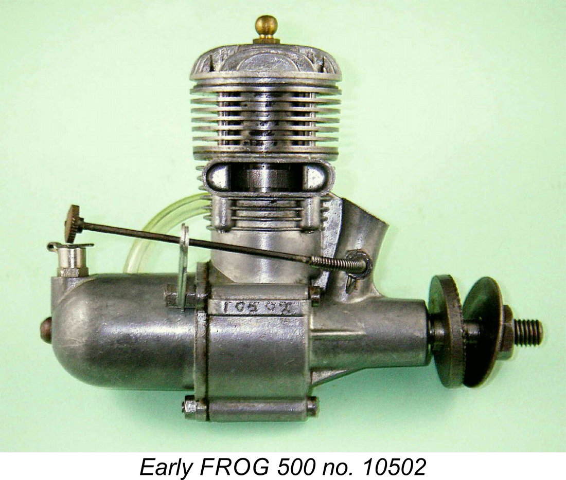 Here we’ll share an in-depth look at one of the most enduringly popular British middle-displacement model engines of the mid 20
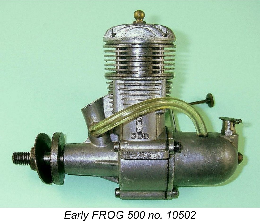 Foremost among those who assisted were my good mates David Owen (now sadly no longer with us) and Jon Fletcher, both residents of Australia. These valued friends not only provided a mass of serial number data but also most generously shared a wealth of knowledge and insight. As a result, I was able to examine the engine’s background in far greater detail than I was expecting. Moreover, that background proved to be a good deal more interesting and complex than anticipated. Many thanks, blokes - we’re all in your debt!
  As of the late 1940’s, IMA was already one of the world’s oldest-established model aircraft manufacturers, having been founded in 1931 by Charles Wilmot and Joseph Mansour in association with Wilmot’s brother John. The trade-name "FROG” ("Flies Right Off Ground") was used by IMA from the outset for their popular flying model kits, later being carried over to their engines as well. Note how cleverly the monograms of the founders (W and M, highlighted in colour in this image) were incorporated into their FROG logo ...........
  In early 1932 IMA solved their growing product distribution problems by becoming part of the very prolific Lines Brothers organization. This company had been a major player in the British toy industry since 1919, continuing a Lines family involvement in that industry which had begun in around 1850. Lines Brothers also owned the famous Tri-ang toy brand, the triangle emblem of which represented
 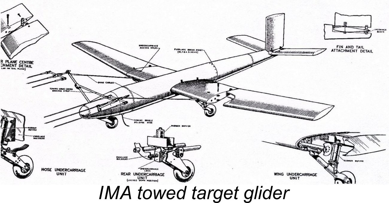 During WW2, the Lines Brothers organization understandably became preoccupied with the production of military materiel, notably the iconic Sten gun as well as other military hardware. The facilities of their IMA subsidiary were applied to the production of both large aircraft-towed gliders for target purposes and 1:72 scale static models for aircraft identification training. Production of the 32 ft. wingspan Mk. III aircraft-towed target glider actually continued under government contract long after the end of the war.
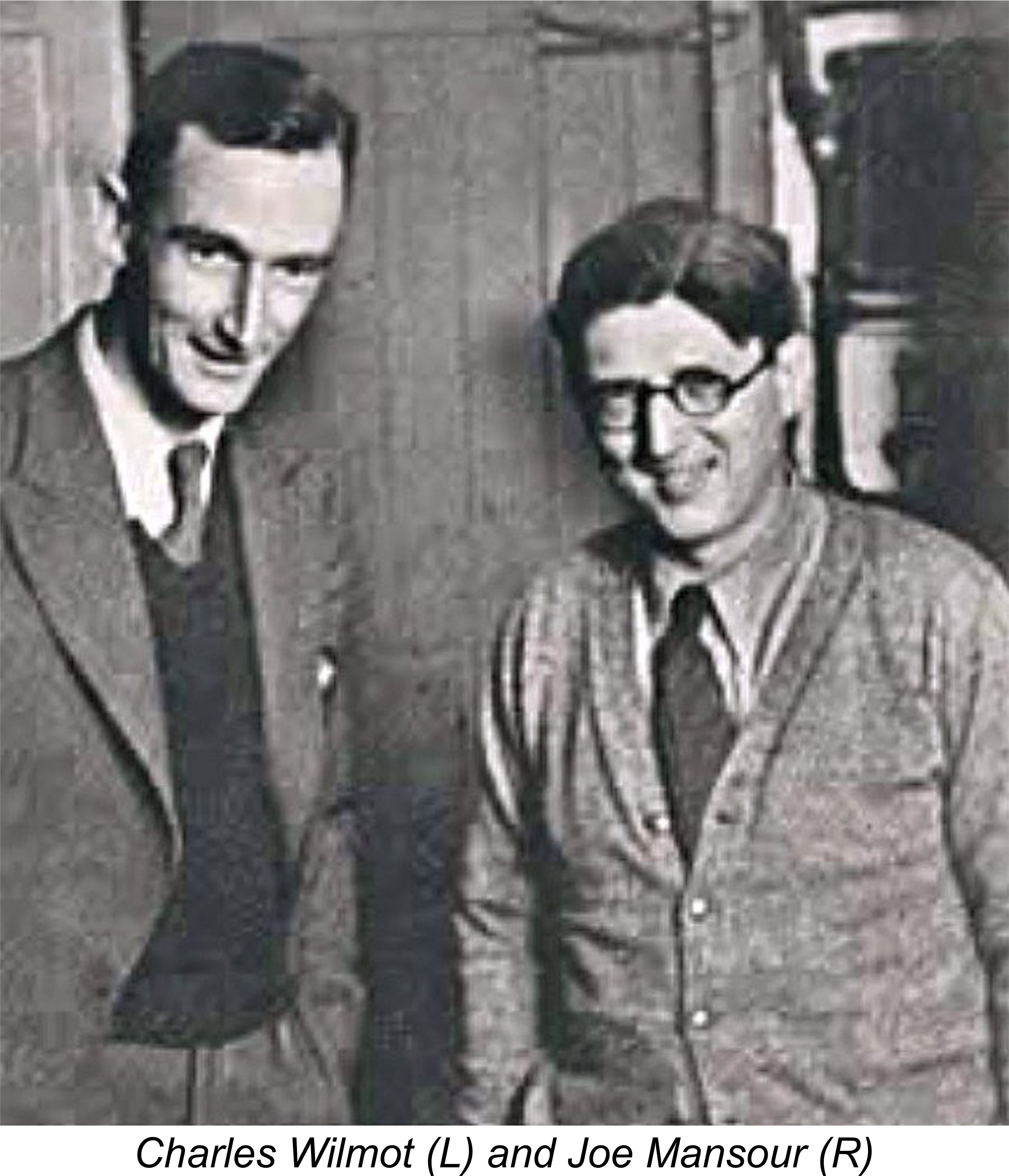
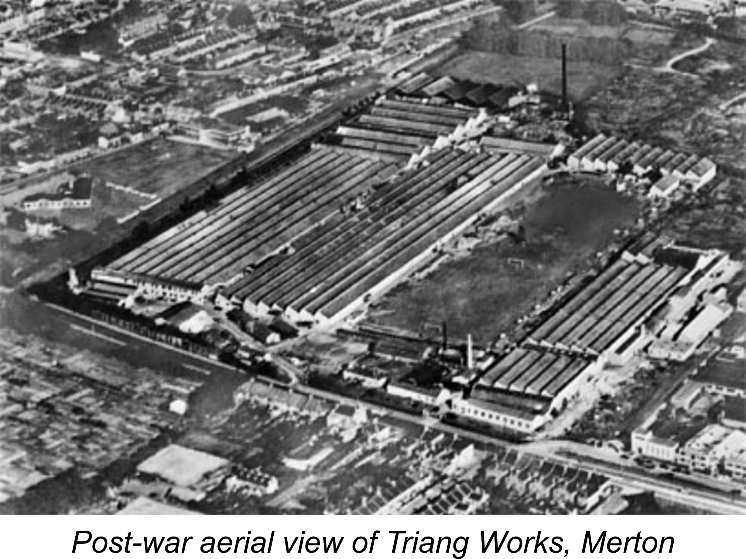 Established in 1925, this facility was known as Tri-ang Works. By the time of which we are speaking it was claimed to be the largest toy and model production facility in the world, occupying some 750,000 square feet of floor space and employing over 4,000 people. It generated enough business to justify its own half-mile rail siding.
  Using these excellent facilities, IMA began the development and manufacture of model engines at Morden Road soon after the conclusion of WW2. Model engine production was of course an activity which was completely distinct from IMA’s previous manufacturing programs, requiring very different skills and equipment. It is therefore greatly to the credit of 1936 Wakefield Trophy winner A. A. “Bert” Judge that the company’s entry into this new market area was such an immediate success. Judge had started with the company in 1936 at the age of 19 after winning the Trophy at an International meeting held at Detroit, Michigan. In 1946 he was put in charge of IMA's post-war engine development and manufacturing program.
 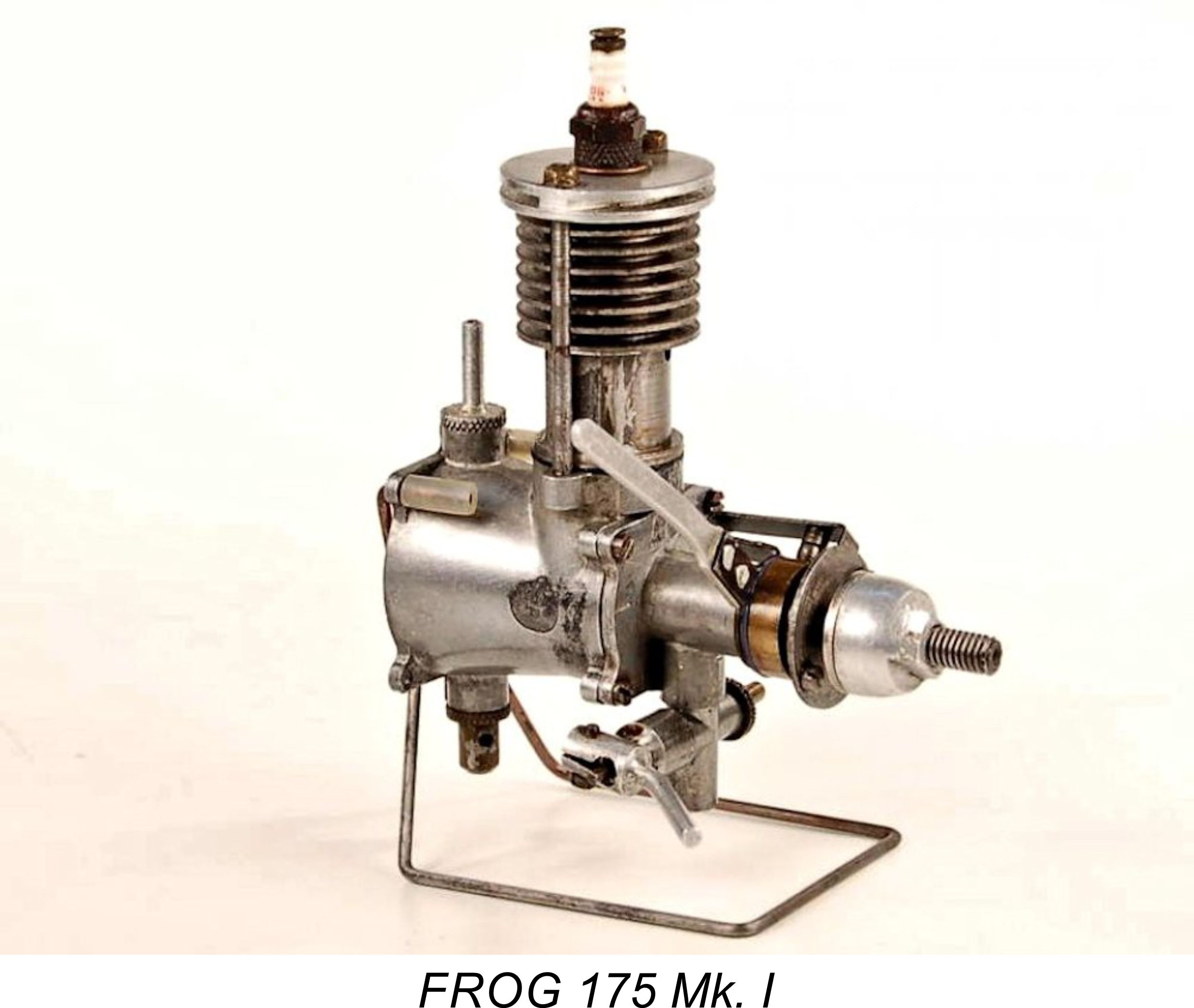 contributed an article on one of Court’s early prototypes of the
  While all of this was going on, IMA had begun to investigate the possibility of expanding their model engine range into the larger-displacement category. Thanks to my late and much-missed mate David Owen, I’m able to chronicle this matter in far greater detail than I believe has ever been possible previously. This opportunity arose as a result of a visit paid in the year 2000 by David (in company with the late and equally-missed Gordon Burford) to C. R. “Bob” Bright, an engineer formerly of London, England who had relocated to Australia in mid 1951. Bob was then living in the Castle Hill area of Sydney and remained active in the engineering field, although he has since passed away.
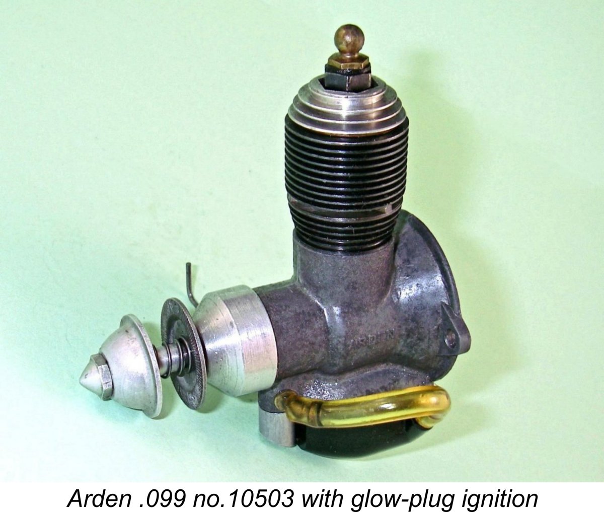
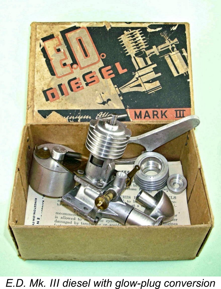 E.D. had got the ball rolling remarkably quickly by developing a glow-plug conversion kit which was supplied with their
 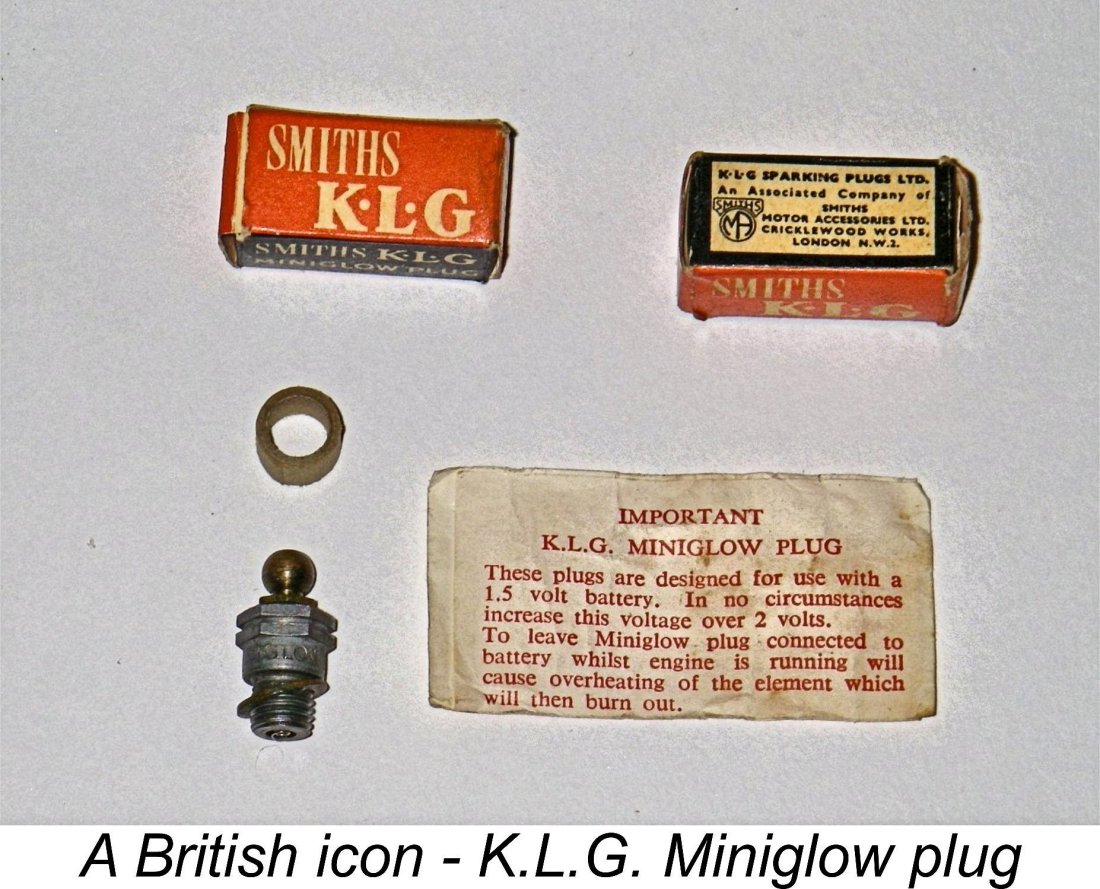 It cannot have escaped IMA’s notice that by mid 1948 an increasing number of people were operating their FROG 175 spark ignition models on glow-plug ignition in order to eliminate the dead weight and inconsistent dependability of the ignition system. The sun appeared to be rising upon the glow-plug engine in Britain.
 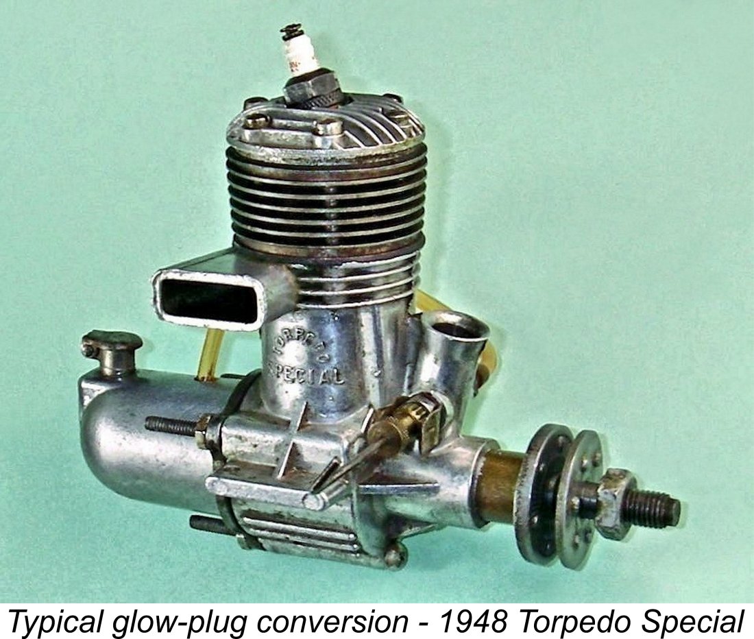 As of mid-1948 there were no established engines in Britain which had been expressly designed from the outset for glow-plug operation. Indeed, there were very few such engines anywhere, even in America where glow-plugs were mainly employed in conversions of existing spark ignition designs at this stage. The illustrated Torpedo Special .29 was a typical example - it had been designed as a spark ignition model back in 1946, being converted to glow-plug operation simply by omitting both the timer and the required extra machining to mount it, with no other changes.
 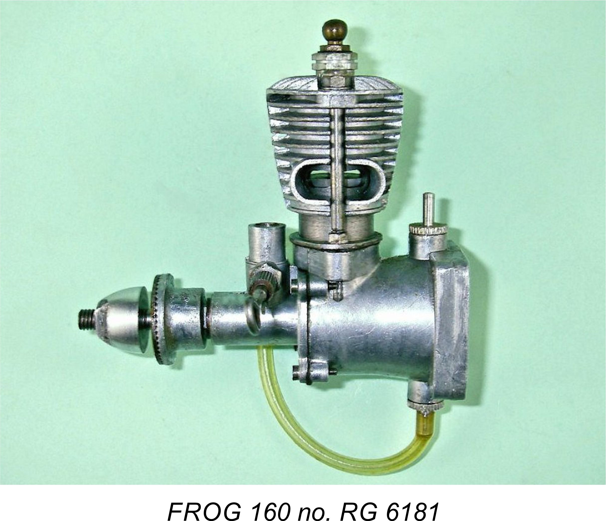 But that lesson had yet to be learned, and meanwhile this was by far the least expensive option. Moreover, IMA had a very suitable candidate for conversion already in production in the shape of the well-established 175 spark ignition model which had recently been updated. The creation of a glow-plug conversion for this model would involve minimal expense - essentially all that was involved was the elimination of the timer!
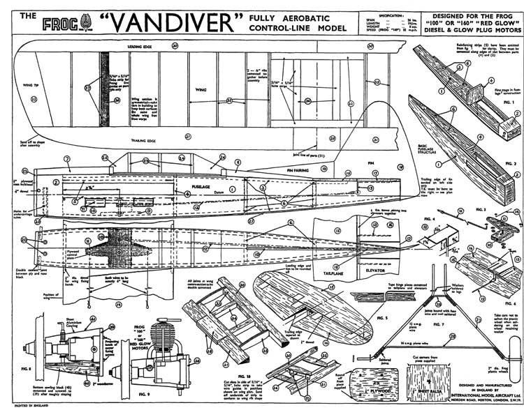
 As 1949 rolled around, the glow-plug motor had gained a firm foothold in the high-performance market in Britain, particularly in the middle and larger displacement classes. The Americans had quickly leapt out to a wide lead in the glow-plug design department, but prevailing trade restrictions ensured that engines from the USA were almost unobtainable in Britain at the time unless one had friends or contacts in America or was on good terms with a US serviceman still stationed in Britain. The domestic market was therefore wide open to any British manufacturer who could come up with a design which approached the American designs in terms of quality and performance.
 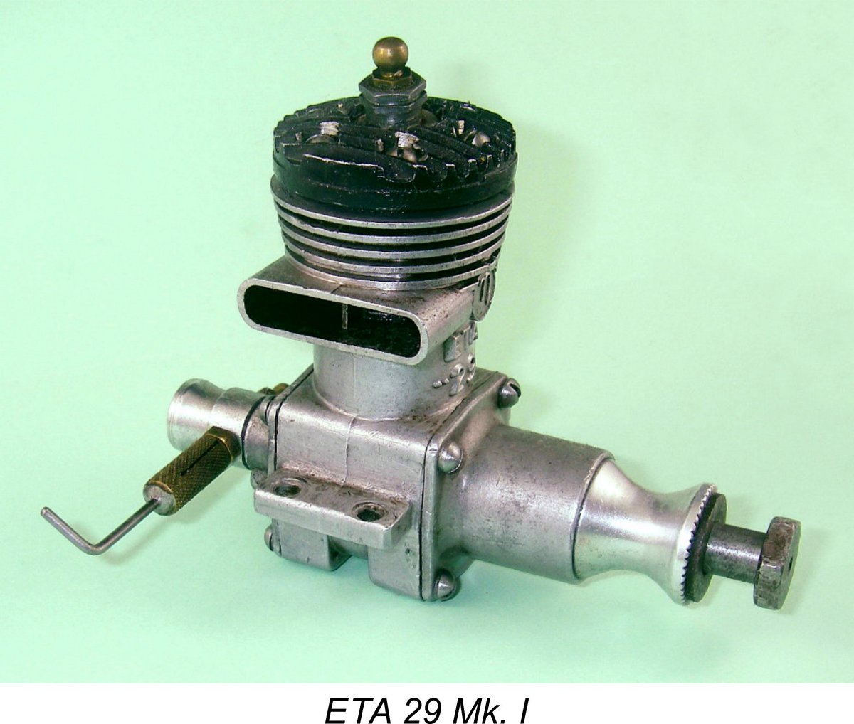 However, this was not true of the larger displacement categories (greater than 3.5 cc). Diesel engines of around 5 cc displacement or larger (such as the
 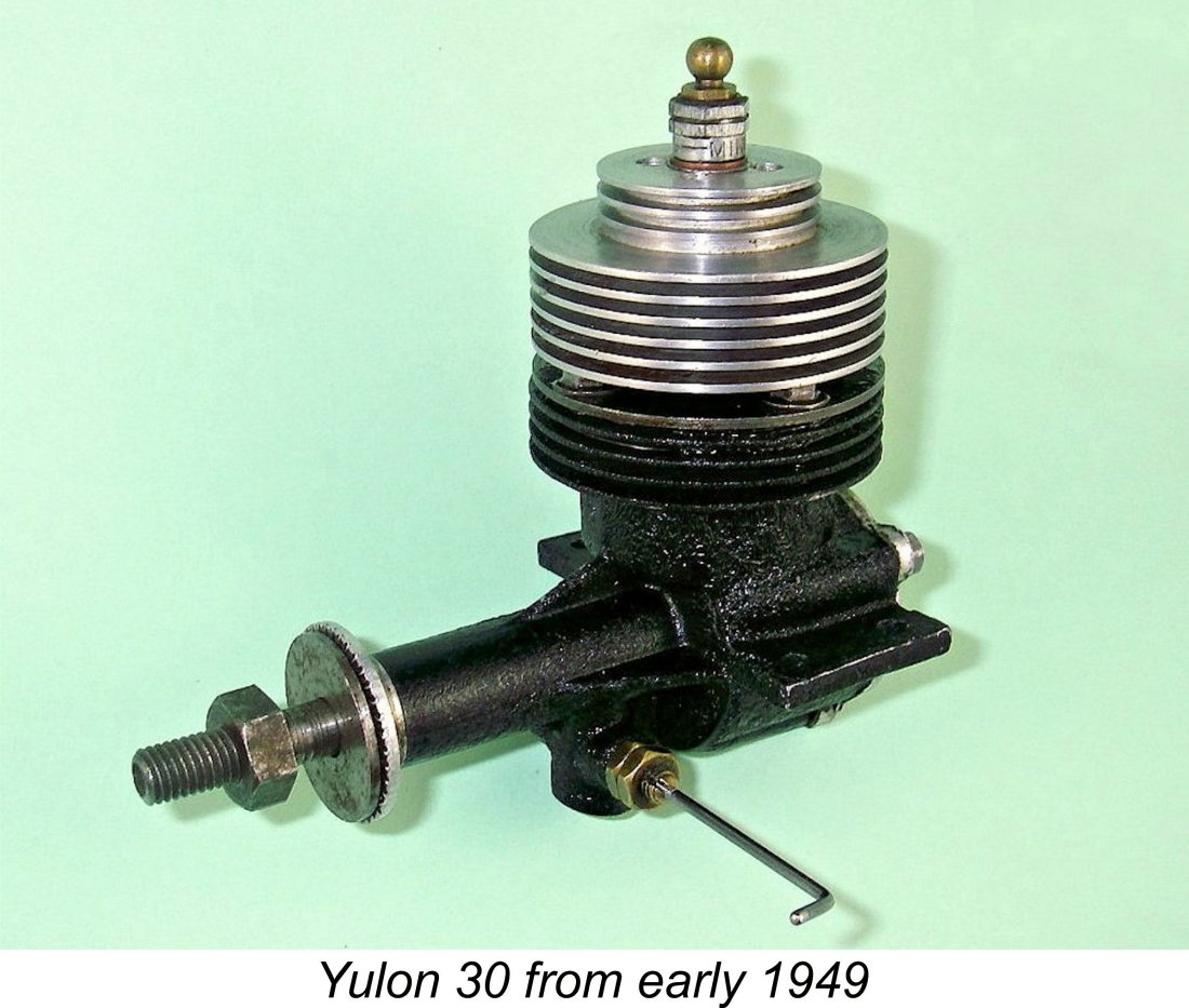 It could not have escaped the attention of IMA that, in the non-racing 5 cc displacement category at least, the domestic competition was pretty thin at the time. Although the radially-ported
 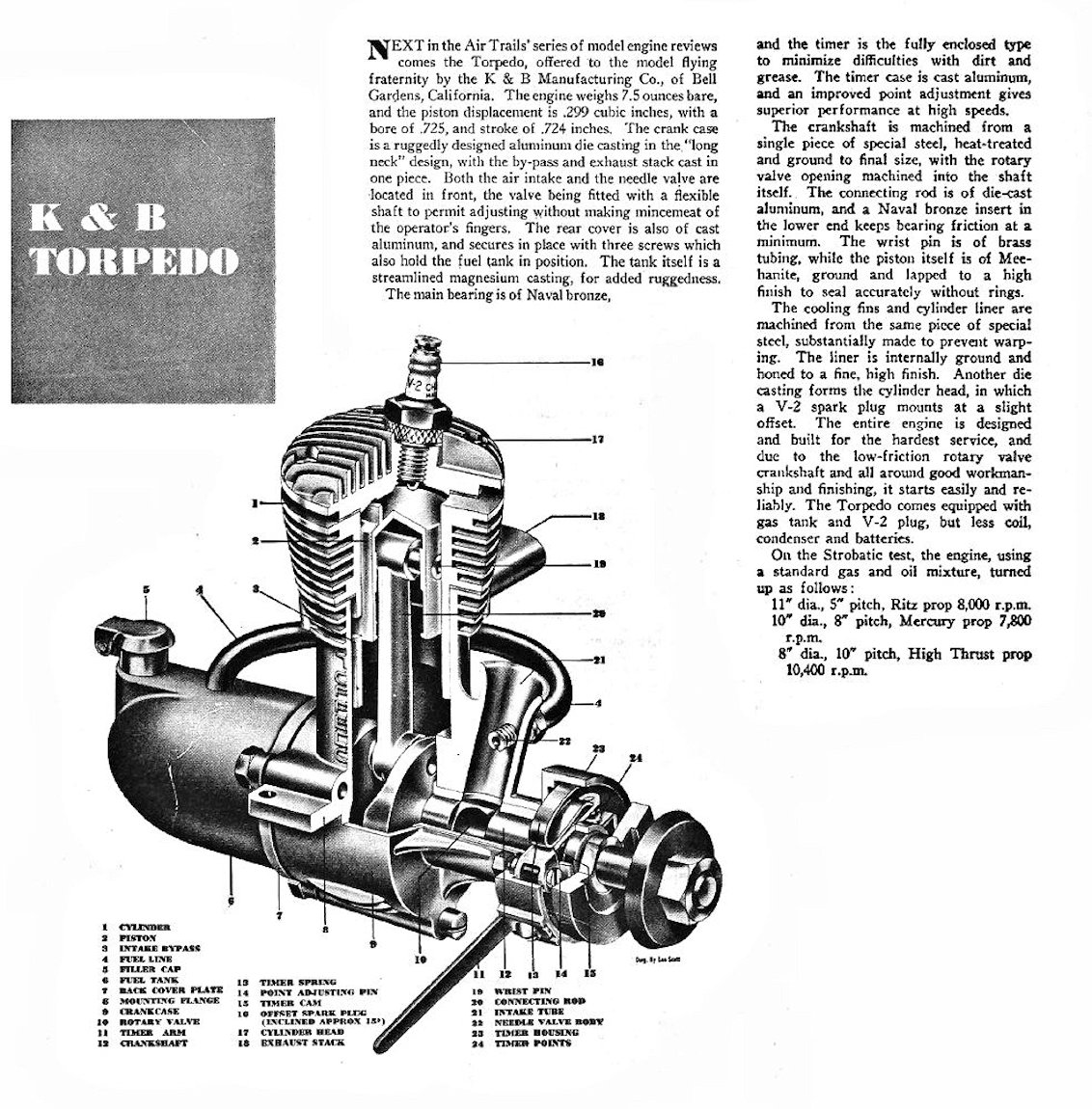 When commencing the development of the FROG 500 back in early 1948, IMA had very sensibly resisted the temptation to re-invent the wheel through major departures from established American design practise. On the contrary, it’s abundantly clear from the architectural and structural evidence that during the period in late 1947 through early 1948 when he was first embarking upon the design of what would eventually become the FROG 500, Bert Judge had somehow contrived to get at least an arms-length look at the K&B Torpedo 29 sparker, perhaps through published images in US modelling magazines.
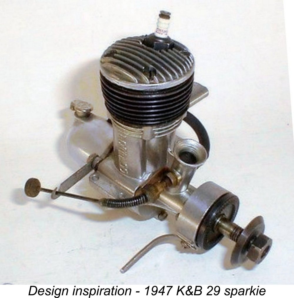
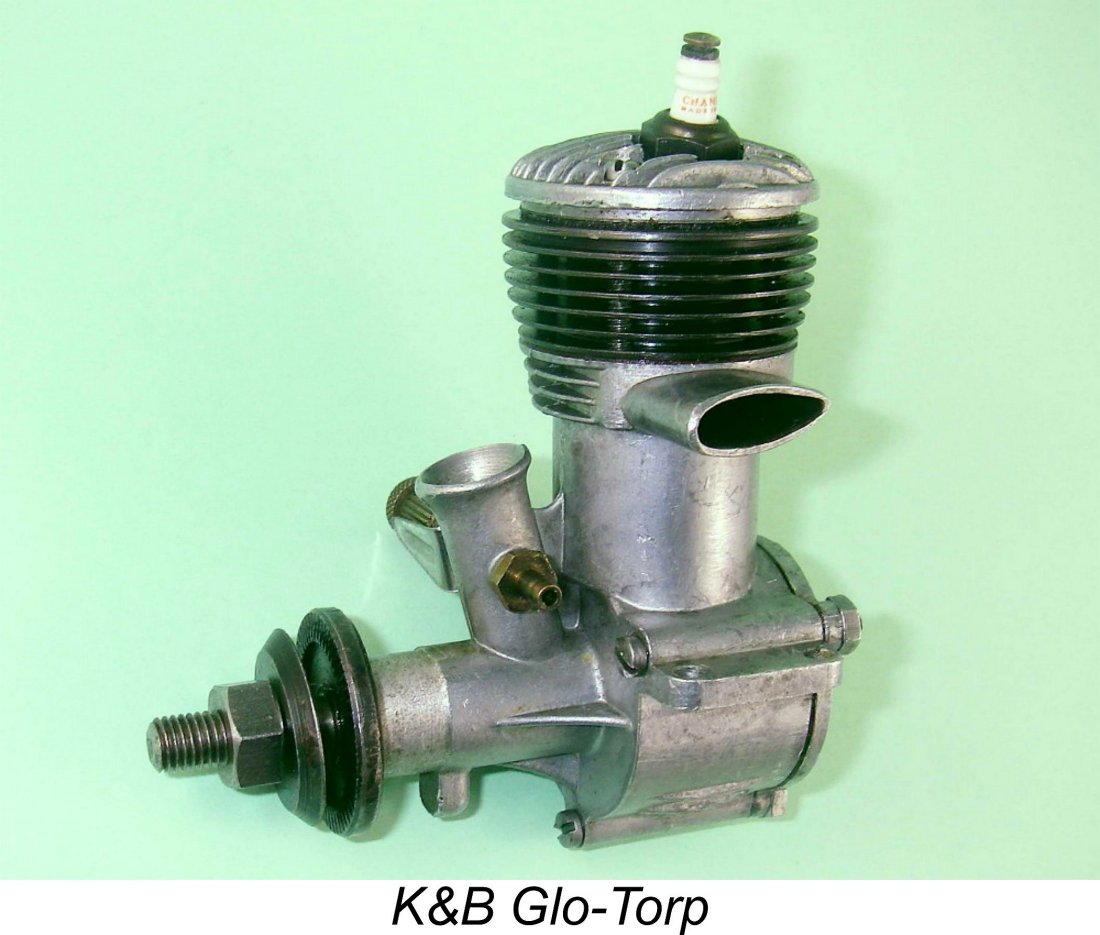 We've seen earlier that IMA had shelved the FROG 500 design in mid 1948 pending a trial of the British response to glow-plug ignition through the release of their cheap ‘n cheerful 160 model. However, there’s little doubt that they kept their eye on developments in America. They must surely have become aware that in October 1948 the K&B Torpedo 29 sparker was joined by a purpose-built glow-plug version designated the Glo-Torp 29. This was essentially identical to the Torpedo 29 spark ignition model (which remained available until December 1950) except that the front of the main bearing housing was not machined to accept a timer.
 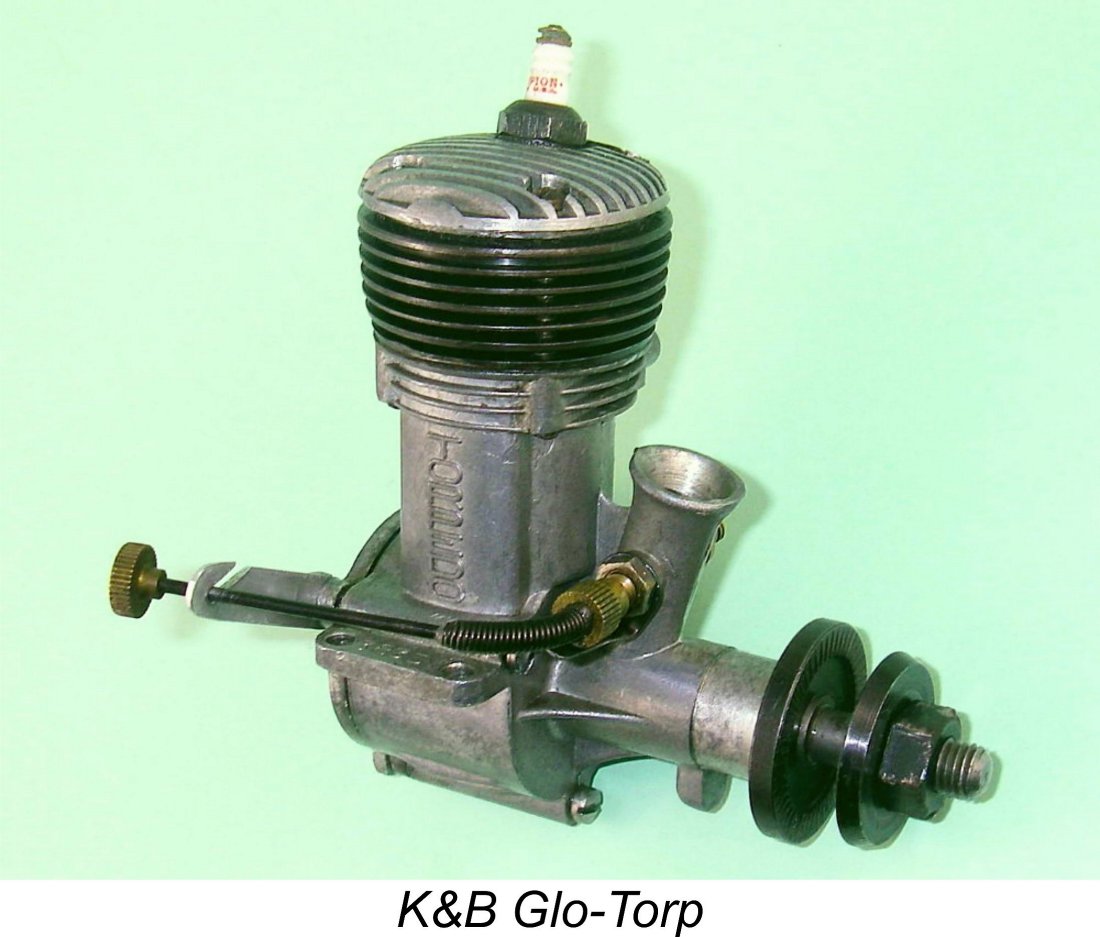 The Glo-Torp 29 proved to be a fine runner, combining good durability and excellent handling qualities with a more-than-adequate power output for all purposes other than pure racing applications. Consequently, it sold very well on the US market, achieving sufficient renown for the K&B name to become known outside America in well-informed circles. Based upon the known serial number sequence, some 13,000 examples of this model were produced between October 1948 and July 1951 (a respectable average of some 400 units monthly), when it was replaced by a revised glow-plug 29 offering. My sincere thanks to my good mate Tim Dannels for making this information readily available through his invaluable “
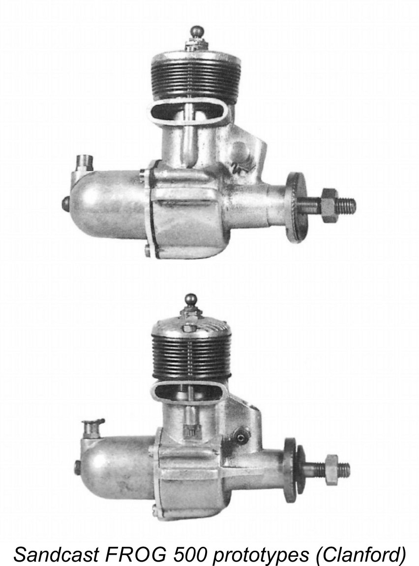 We saw earlier that in 1948 IMA had chosen to test the glow-plug market by converting their existing 175 model to glow-plug ignition rather than following the more costly path of completing the development of the 500 as a glow-plug model. We noted the implication that they had made little progress towards the creation of tooling or the manufacture of any major components for the 500 at that stage. It has been suggested that they may have got as far as manufacturing the first batch of cases and perhaps even the timers for this model before the project was put on hold. However, this view is at odds with the existence of several sand-cast prototypes of the FROG 500 in glow-plug configuration, with no provision for a timer.
 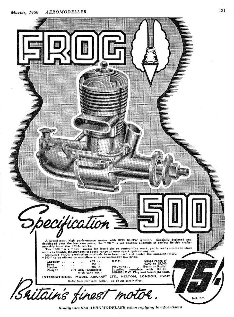 A degree of ambiguity has hitherto surrounded the date of the FROG 500’s initial appearance. As far as I’ve been able to determine, the first national advertisement for the new model appeared as a full-page placement by IMA in the March 1950 issue of “Aeromodeller” magazine, as reproduced here. However, in a number of later articles Peter Chinn repeatedly and specifically referred to the engine as having been introduced in “late 1949”, commenting upon its immediate acceptance by the British modelling public at that time.
 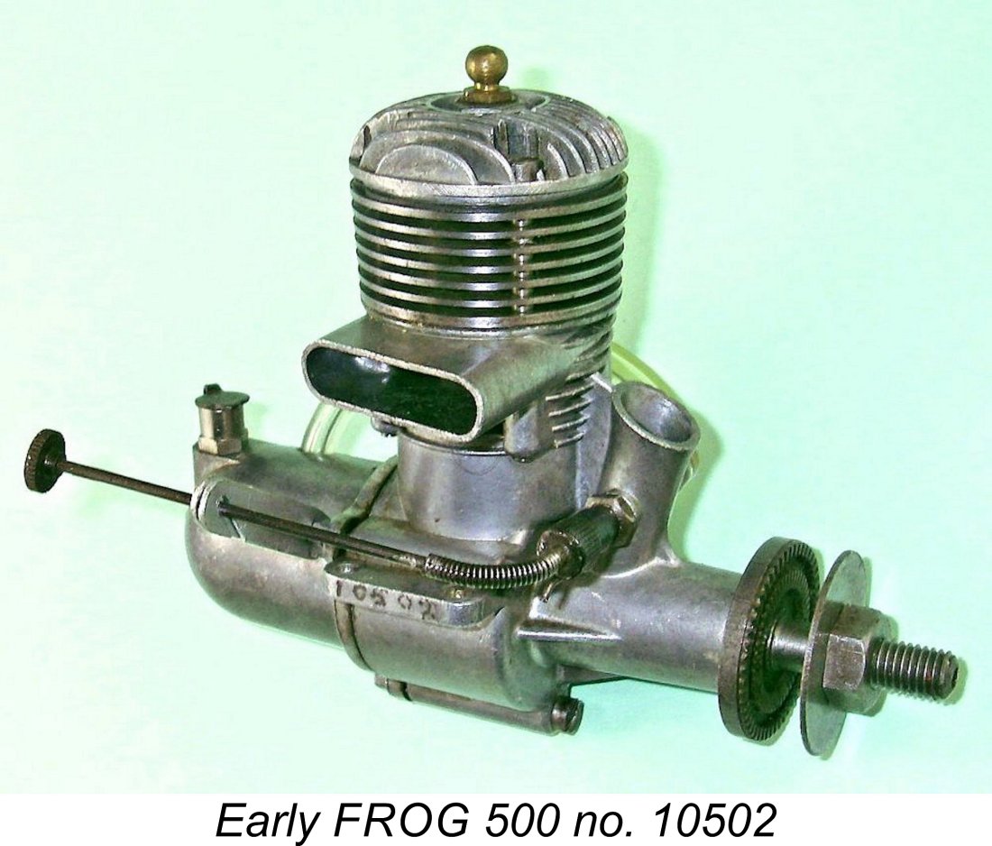 We may as well begin with the basics. The FROG 500 was a conventional crankshaft front rotary valve (FRV) cross-flow loop-scavenged plain bearing glow-plug motor featuring a lapped cast-iron baffle piston operating in a case-hardened mild steel cylinder. Compression ratio was approximately 7:1. The engine weighed in at 7.65 ounces (217 gm) complete with plug, tank and fuel tubing.
 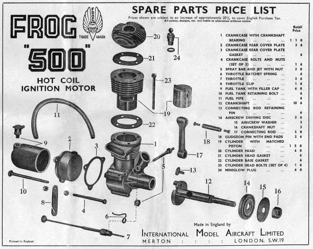 The design of the FROG 500, like that of its K&B progenitor, was completely conventional for a plain bearing loop-scavenged FRV glow-plug motor of the late 1940’s. Hopefully the attached exploded view will help to make its construction clear. Note that the piston is shown in the drawing with the baffle location reversed - it should be on the transfer side!!
 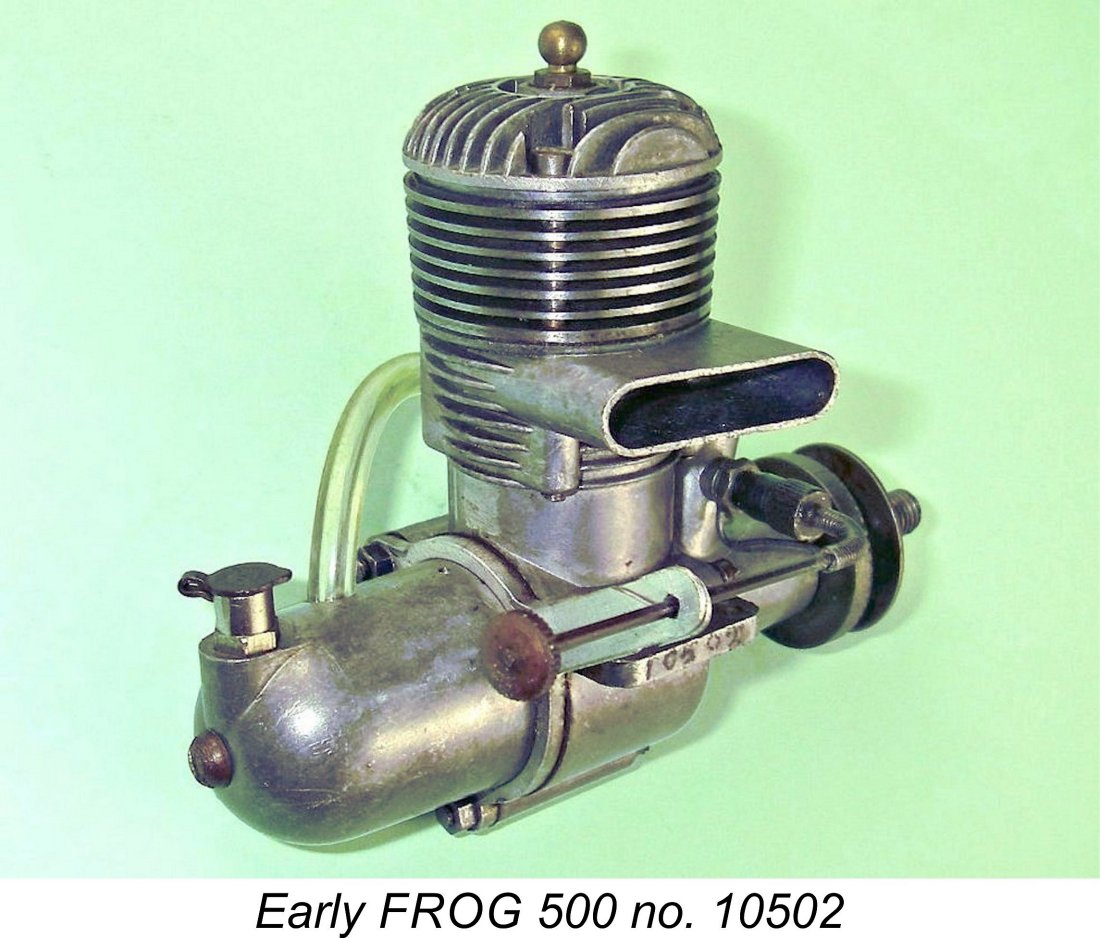 The backplates of both designs were pressure die-castings which were retained by three nut-and-bolt combinations running axially from the front through the full length of the crankcase casting. Finally, both models featured needle valves having flexible spring-mounted extensions which could be held in a rearward alignment for safe manipulation by a slotted retainer clip attached to the rear of the engine using one of the backplate retaining nuts. The K&B design was changed in early 1950 to a solid thimble, but the FROG retained its flexible needle throughout.
 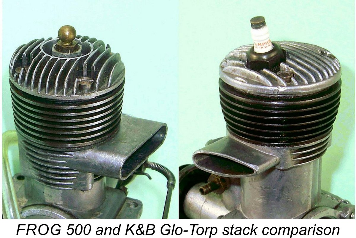 In terms of the visible differences between the two designs, the first and most obvious was the exhaust stack configuration. The Glo-Torp adopted the “trademark” K&B stack orientation of discharge to the left of the engine (facing forward in the direction of flight). By contrast, the FROG’s exhaust stack was more conventionally placed on the right viewed from the same perspective. In addition, the FROG’s stack had a conventional round-ended ”race track” section, while the K&B adopted a streamlined “tear drop” shape. In both cases, the outer end of the stack was angled towards the rear of the engine in plan view. Finally, the cross-sectional area of the FROG stack was considerably greater than that of the K&B.
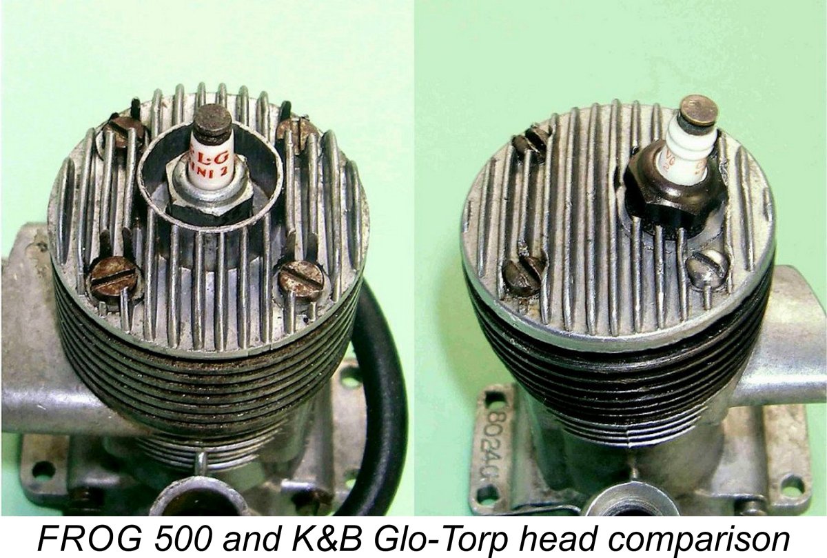
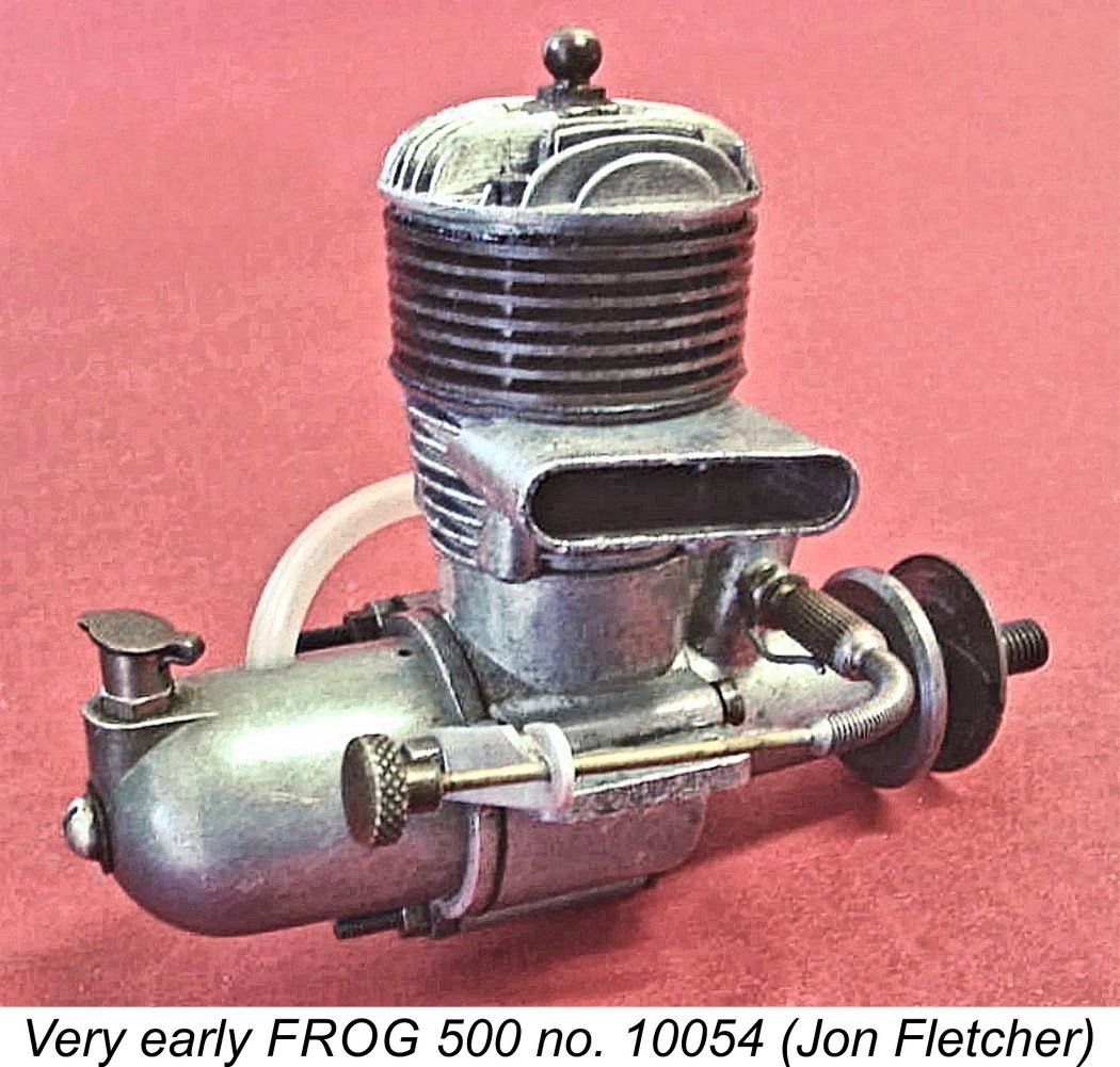 A difference in the material specification was initially to be found in the main bearing sleeve. Peter Chinn mentioned the fact that as originally released, the FROG 500 featured a machined cast iron sleeve as opposed to the bronze component used in the K&B. Jon Fletcher’s very early engine number 10054 confirms this observation. However, the material of the FROG’s main bearing was very quickly changed to machined phosphor bronze - my own early example number 10502 exhibits this change. The early variant was thus extremely short-lived, apparently being confined to the first batch of 500 or so engines. This early version with the cast iron bushing is probably the least-common FROG 500 sub-variant today, although the difference is not externally apparent.
 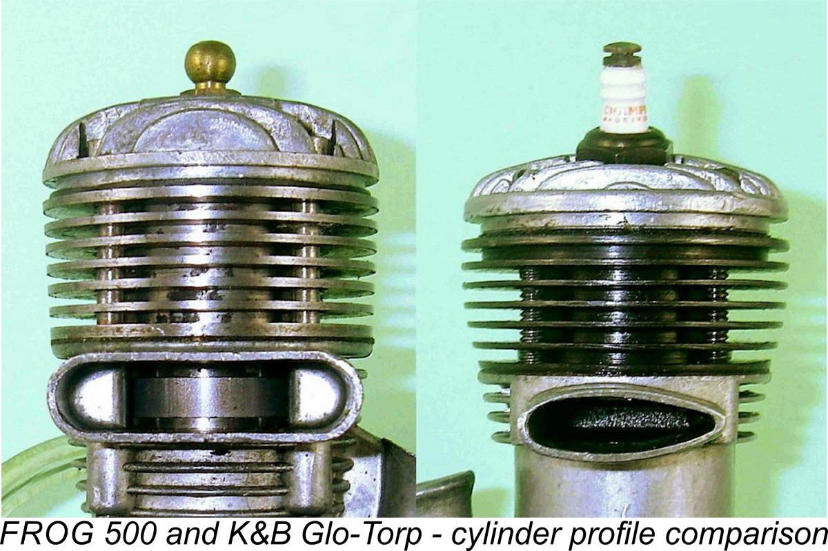 The treatment of the cylinder was also slightly different. Like those of the K&B model, the cooling fins of the original FROG design were tapered outwards towards the top in side profile, although to a far lesser degree than those of the K&B model and also lacking the slight curvature of the side profile seen in the K&B. The purpose of this taper was to make the diameter of the lower fin (which served as the cylinder location flange) correspond to that of the crankcase upper surface. However, while the heat treatment applied to the steel cylinder of the K&B apparently included a degree of brittleness relief, that of the FROG 500 was case-hardened all over. This process resulted in a high degree of brittleness in the FROG cooling fins, which therefore required respectful treatment if breakage was to be avoided. Examples with broken fins are not uncommonly encountered today.
 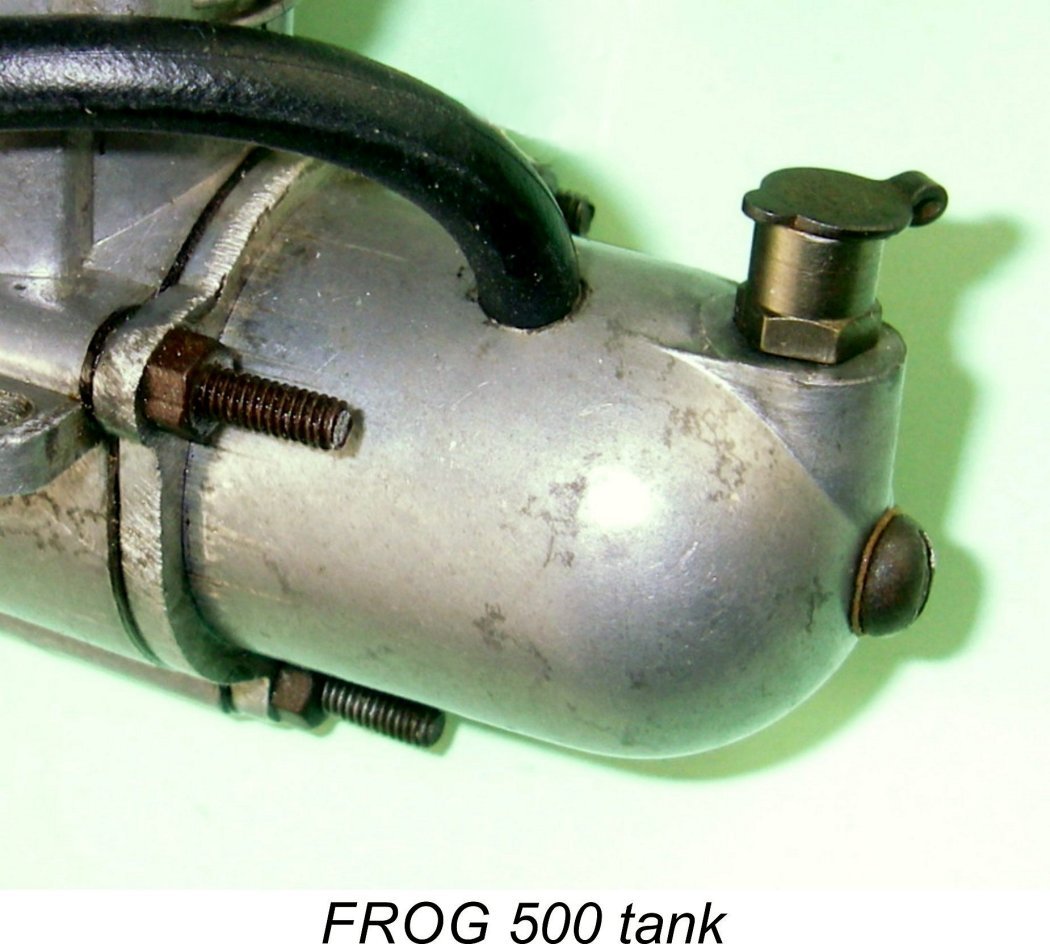 The final difference worth mentioning was the fact that, unlike the Glo-Torp 29, the FROG 500 was always sold with a tank. This was patterned very much along the lines of the component supplied with the spark ignition K&B Torpedo, likely reflecting the initial design influence of that model. Naturally, many owners discarded these tanks in favour of a more suitable unit for the specific purpose to which the engine was to be applied. Consequently, examples complete with tank are significantly less common today than those without tanks, a factor which does not affect the usability of these engines but has a considerable bearing upon their present-day attractiveness to collectors. The late Woody Bartelt did us a great favour by having a short series of excellent replica FROG 500 tanks produced in 2015, but they are now long gone, as sadly is Woody ………..
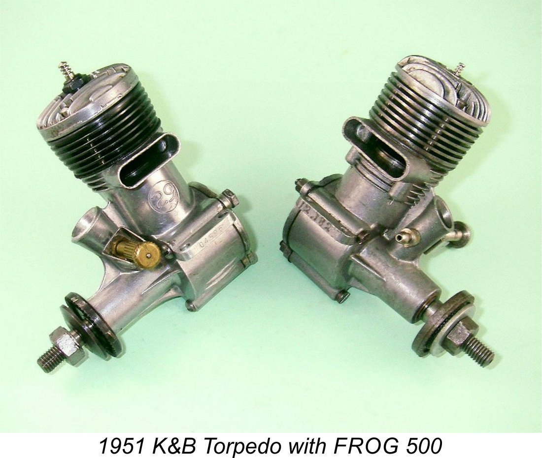
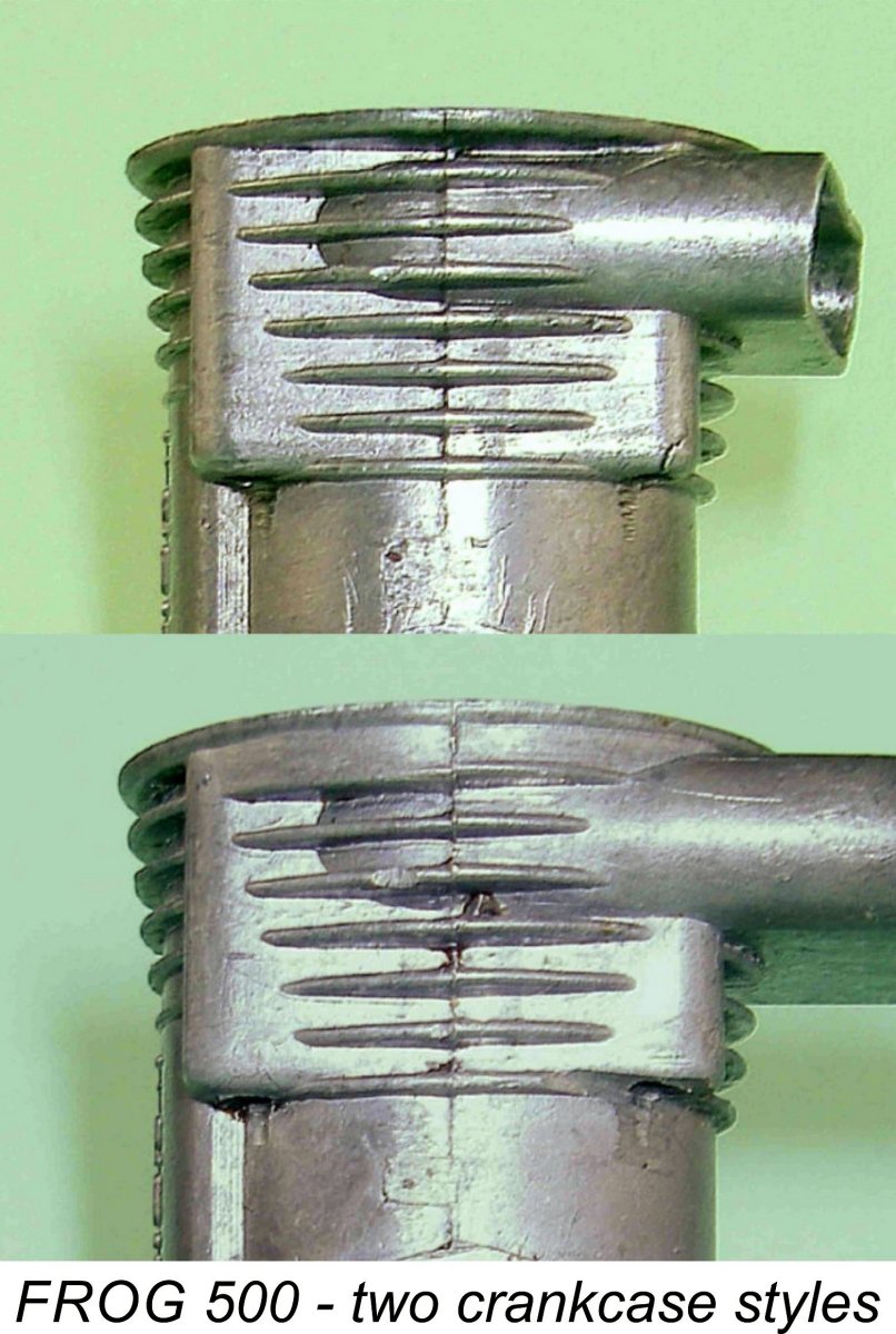
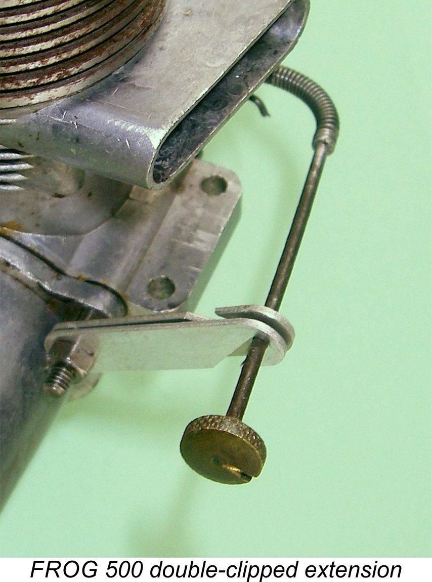 Along with its many excellent qualities, the FROG 500 exhibited a number of somewhat annoying design features which require discussion at this point if I’m serious about meeting my usual objective of presenting a balanced view of the engine. A number of these issues should be read as warnings for present-day users!
 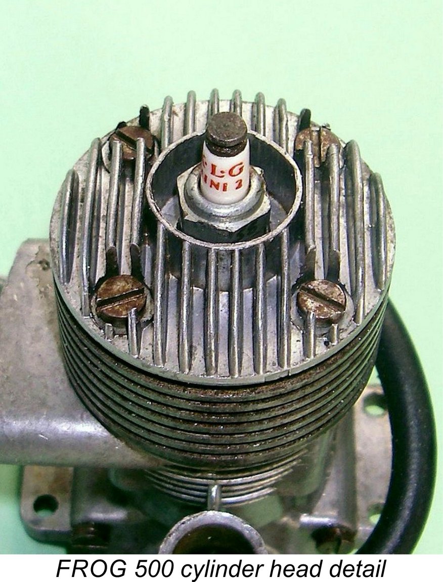 Another aggravating feature was the fact that the plug was surrounded by a thin circular “wall” of metal which created a recess for the plug. The intent of this appears to have been to stabilize the central head cooling fins. However, this recess was both unnecessary and indeed counter-productive in that it impeded the flow of cooling air over the plug body as well as quickly becoming a “reservoir” of goop! Worse, its internal diameter required the use of a socket spanner of a certain maximum external diameter which also matched the short-reach KLG Miniglow plug fitted as standard. Many modellers evidently did not possess such a tool. This explains why the majority of FROG 500’s which have seen extended service have distorted or broken walls around the plug resulting from attempts to change the plug using unsuitable tools. The use of a very brittle near pot-metal alloy in the FROG castings didn’t help either.
 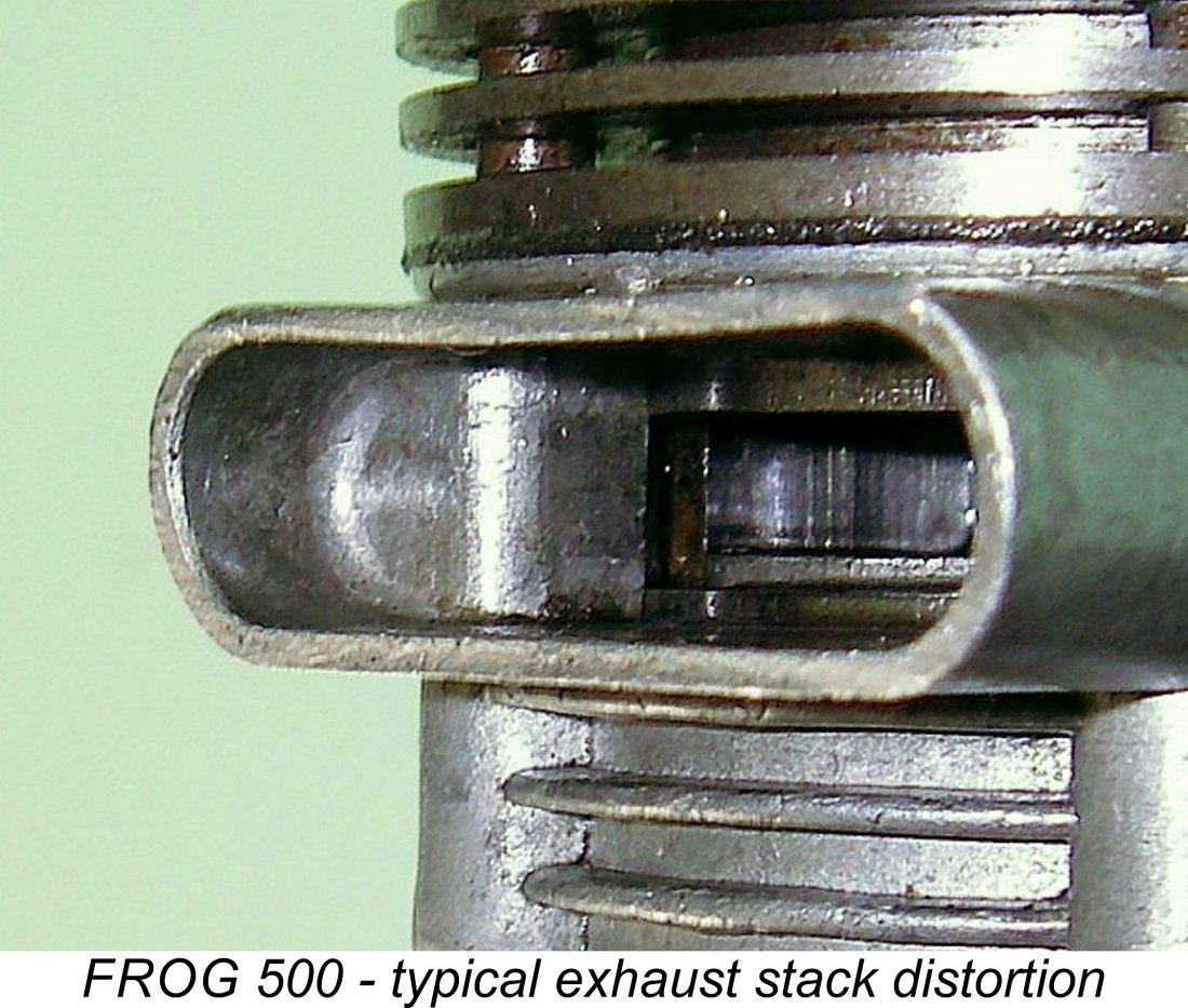 Another issue which was more of a minor irritation than anything else was the stack design. The “race-track” configuration of the FROG stack resulted in long flat top and bottom surfaces between the rounded ends. Unlike the prototypes to which reference was made earlier, there was no supporting pillar in the centre of the stack, leaving its thin upper surface unsupported at the centre. When the cylinder was fully tightened down, the pressure from the thick gasket used between the case and the cylinder locating flange usually bent the upper wall of the stack downwards in the centre. Admittedly this didn’t affect running, but it looked like hell!
 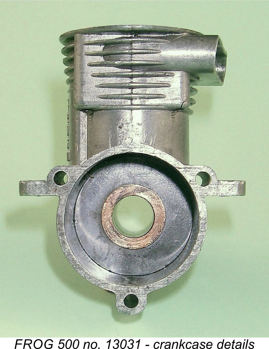 The mounting lugs also don’t escape criticism. They would probably have been fine had it not been for the presence of the axial holes for the upper backplate retaining bolts. The presence of these holes removed a good deal of strength from the upper portion of the lugs at the point of connection to the main crankcase casting. Consequently, breakage of the mounting lugs as a result of crash impacts was not unheard-of. Once again, the use of a casting alloy of very indifferent quality did nothing to improve this issue.
 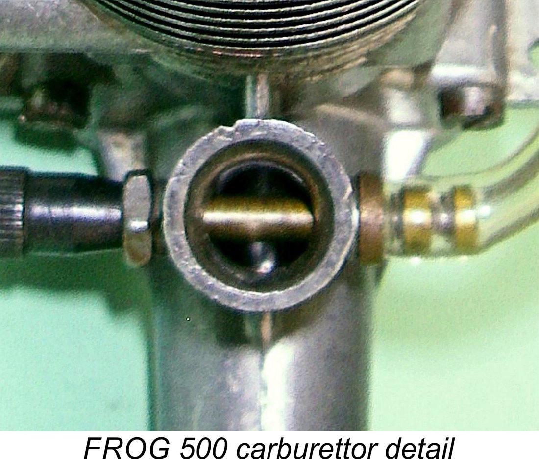 Reference to Maris Dislers’ extremely useful
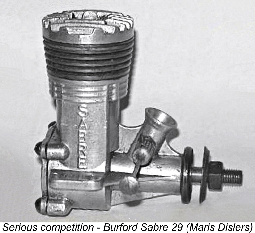
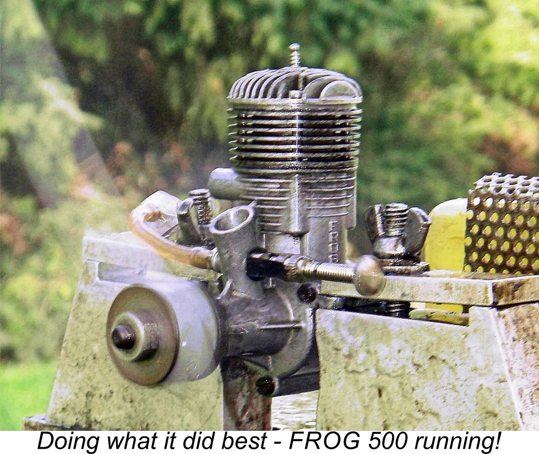
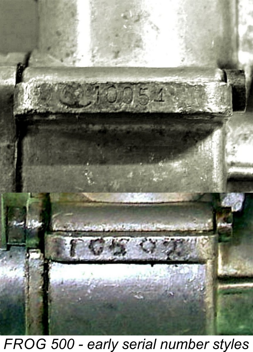 Like all FROG engines, the 500 carried a serial number. Most examples had their serial numbers hand-engraved, although a few of the earliest examples featured stamped numbers - Jon Fletcher’s very early engine number 10054 is one of these. This practise was quickly discontinued - my own early engine number 10502 displays the more usual hand-engraved numbers. The accompanying image documents this change.
 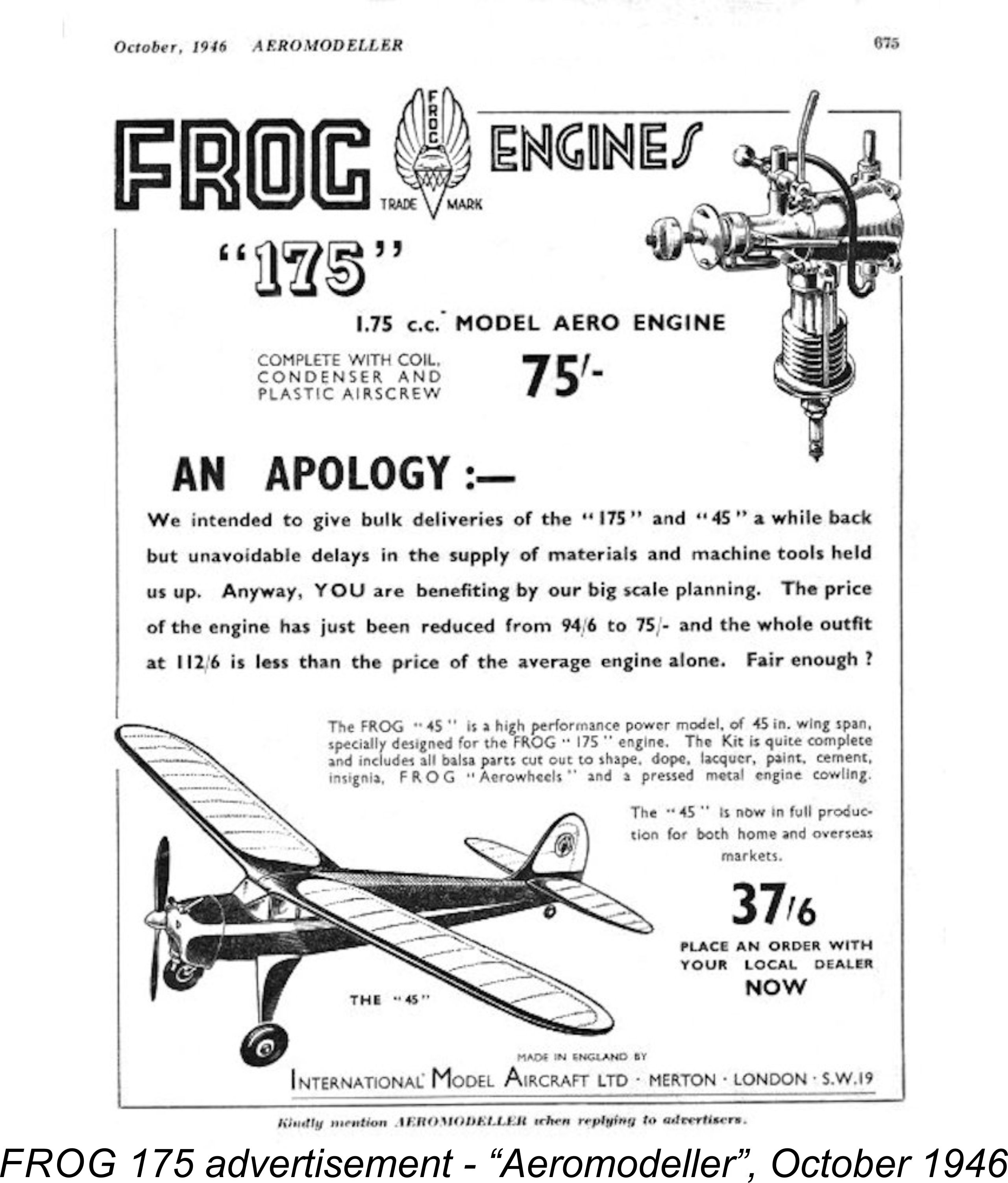 Consequently, we seem to have pretty conclusive evidence to the effect that the 10,000 or so examples of the original thin-lug FROG 500 were all produced over an approximately 18 to 20 month period - a respectable average of some 500-550 units monthly which reflects the immediate popularity of the engine. The rate was probably higher at the outset, tapering off as the initial demand “surge” was satisfied.
  Shortly after Bob Bright’s sudden departure, the staff of the British periodical “Model Aircraft” paid a visit to the IMA manufacturing facility at Morden Road. The resulting report appeared in the January 1952 issue of the magazine. It is reproduced here for reference. At the time, IMA’s claimed model engine production was running at around 1000 units per week of all types combined, with the capacity for increased production if required. Every engine was reportedly test-started at the factory prior to despatch, presumably by a deaf bloke with a prosthetic right index finger!
 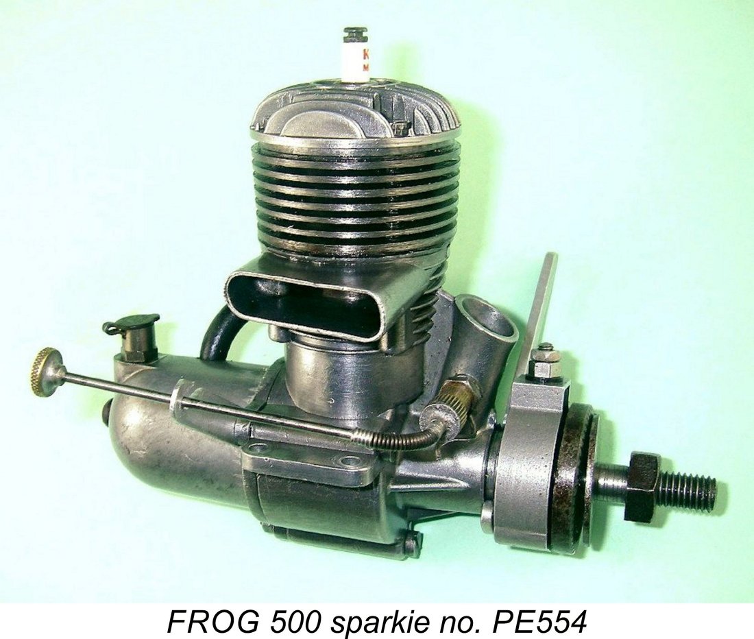 In his May 1950 test of the FROG 500 glow-plug model, Lawrence Sparely noted in passing that plans were then already in hand to introduce a spark ignition (petrol) version. These plans finally became reality in April 1951, when IMA took a step that must have surprised many contemporaries and still appears rather astonishing to us today - they released a spark-ignition version of their then well-established FROG 500 glow-plug model. The previously-noted fact that the serial number sequence for the glow-plug version of the 500 started at 10000 implies that IMA had all along anticipated the potential release of a spark ignition version of the engine, just as suggested by Sparey.
 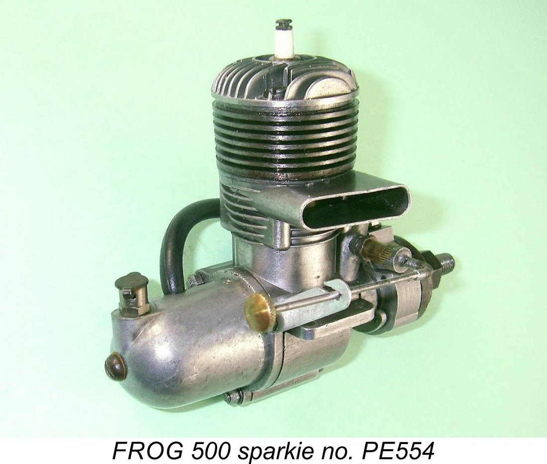 This being the case, it’s reasonable to infer that as of 1951 there must surely have been a die-hard group of British modellers who wished to continue using spark ignition engines for various purposes, most notably R/C flying. The engines which these fliers were using were by then at least 4 years old and getting older each flight! Moreover, the spare parts supply for these motors had long since dried up. These individuals would clearly welcome the opportunity to purchase a new motor to replace their aging and perhaps clapped-out old units dating from the “true” spark ignition era prior to 1948.
 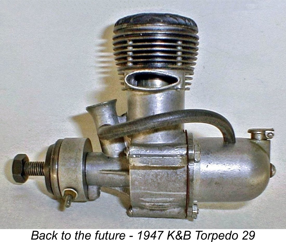 A further point which may have tipped the scale was the fact that IMA already had a design for a spark ignition version of the FROG 500! It’s time to recall the previously-discussed fact that way back in early 1948 they had used the K&B Torpedo 29 sparker as the inspiration for their original FROG 500 design, preparing their initial engineering drawings accordingly. Those drawings were still in existence.
  However it came about, the release of a spark-ignition version of their existing and very successful FROG 500 glow-plug model was an almost unprecedented action on the part of IMA, since it seemingly turned the clock back by three years or so. This version was designated the FROG 500 PE (for petrol engine) to distinguish it from the glow-plug version. The new model sold for a slightly increased price of £4 5s 0d (£4.25). It was announced in the attached advertisement placed by IMA in the June 1951 issue of “Aeromodeller”. Oddly enough, the illustration continued to depict a glow-plug model! The timing of this initial advertisement seems to date the engine's actual appearance to April 1951.
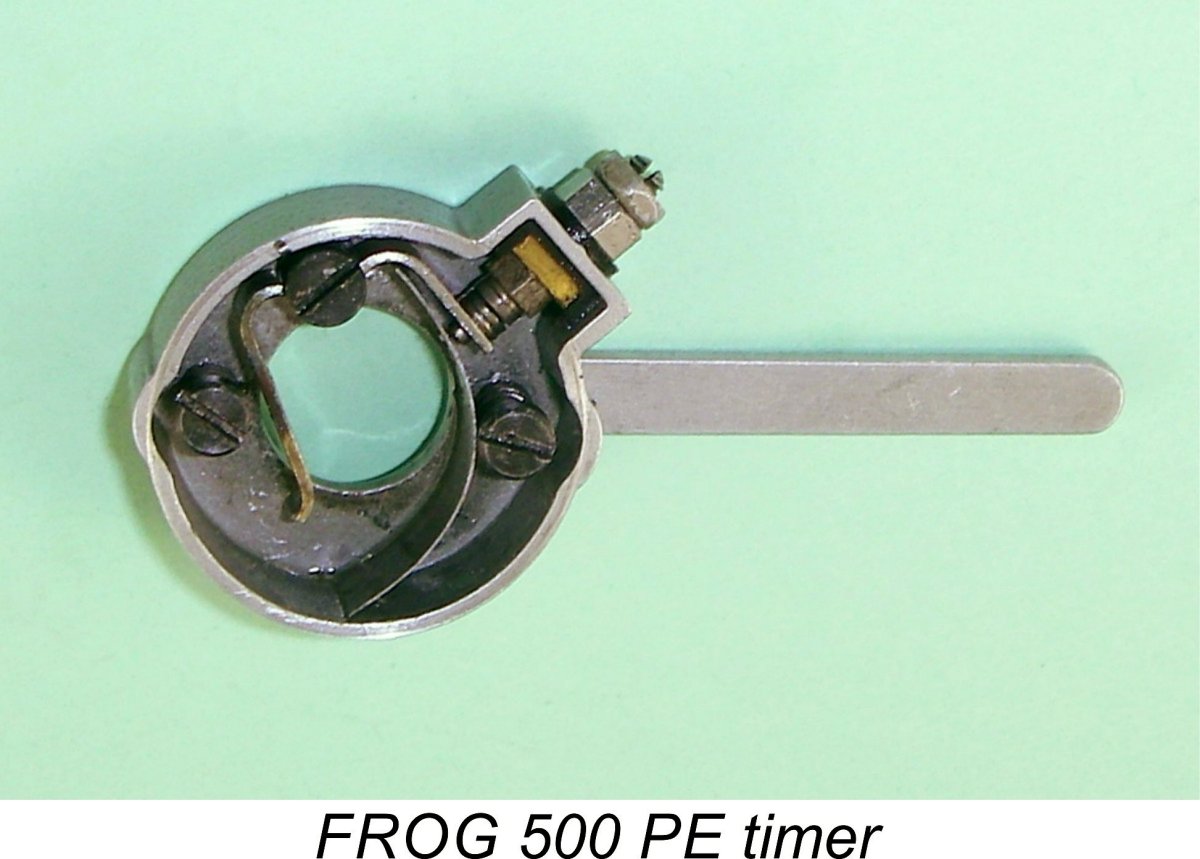
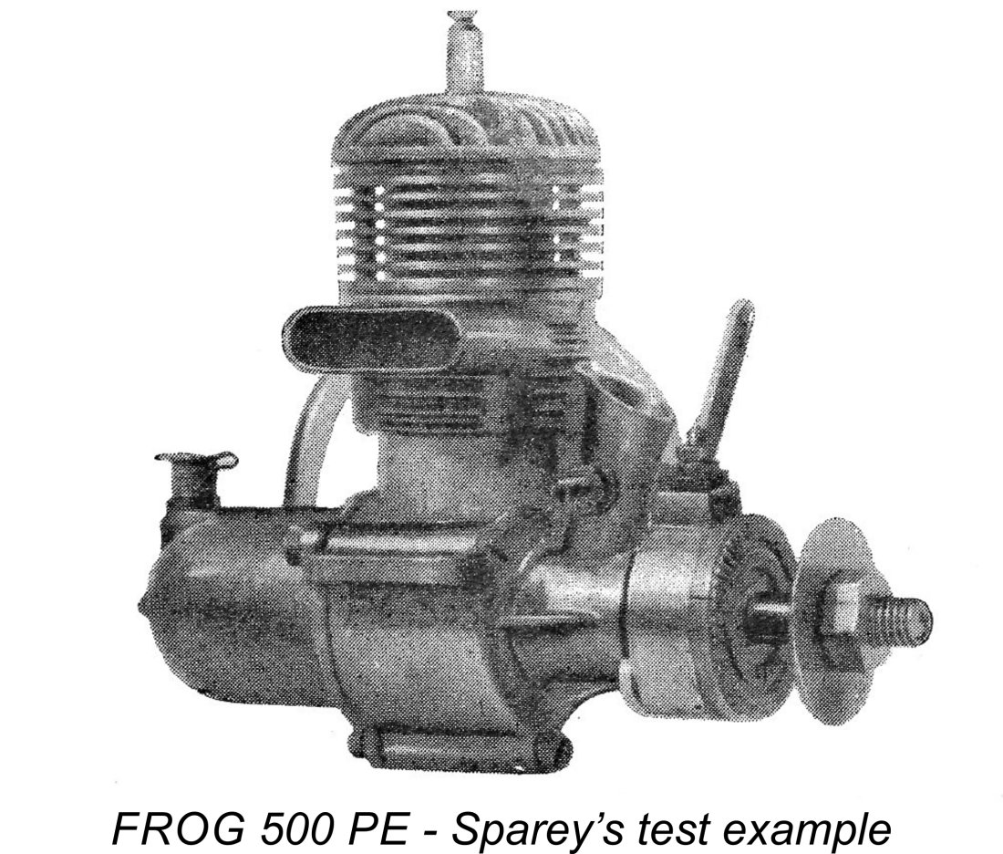 In all other respects, the FROG 500 PE was identical to the companion glowplug model which had been in production for some 18 months by this time. The initial examples featured the same thin-lug crankcase casting along with a plain main bearing sleeve machined from phosphor-bronze. Each engine carried the usual twin serial numbers, which by this time were hand-engraved onto the crankcase. As previously noted, the numbering sequence appears to have been re-started at 1 (or just possibly at 100), with the addition of the PE letter prefix to distinguish this model from the glow-plug version which had by now reached far higher figures.
 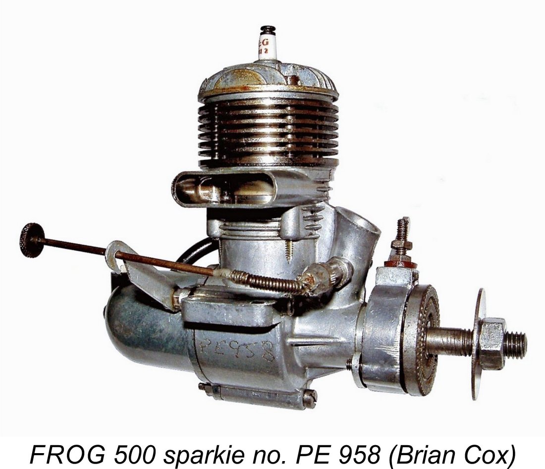 As we shall recall later, a number of additional examples of this model were made using the modified thick-lug crankcase casting which replaced the thin-lug version in mid 1951 (see below). Several PE models of this later type have been confirmed, Brian Cox’s illustrated engine number PE958 being an example. However, the highest serial number yet reported for any version of the FROG 500 PE model is engine number PE1238, again owned by Peter Scott. Just to really confuse things, my own engine number PE1225 has the earlier thin-lug case!! How did this come about?!? The number must be original - there’s no way that anyone could have faked that number onto an original glow-plug case.
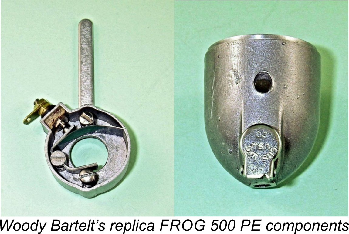
 Chinn went on to note that in such an application, the engine would normally be expected to operate with a large airscrew at relatively moderate rpm, conditions under which most glow-plug engines were not happy due to their inherent
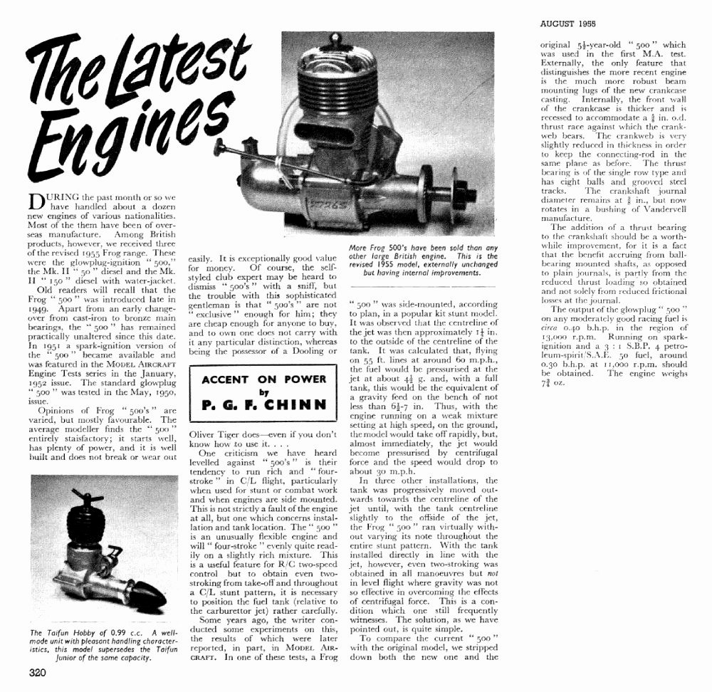 Prior to the original February 2013 publication of this article on MEN, it had been generally assumed that the FROG 500 glow-plug model appeared in two basic variants - the original version with a plain bearing and thin lugs and the final version announced in mid 1955 which featured thicker mounting lugs and a ball thrust race at the rear of the shaft. The main basis for this assumption was Peter Chinn’s announcement and detailed description of this model in his “Accent on Power” column in the August 1955 issue of “Model Aircraft”.
 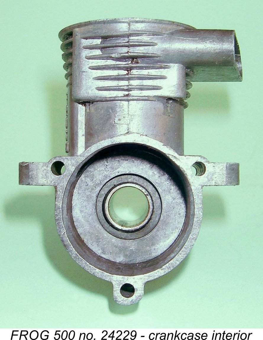 The mystery was solved when Jon Fletcher and I stopped merely scratching our heads and started taking a closer look at our respective stocks of FROG 500 engines and cases. Totally unexpectedly but without exception, every thick-lug case that we examined which bore a serial number below 27000 had a plain bearing! A recess for the eventual fitting of a
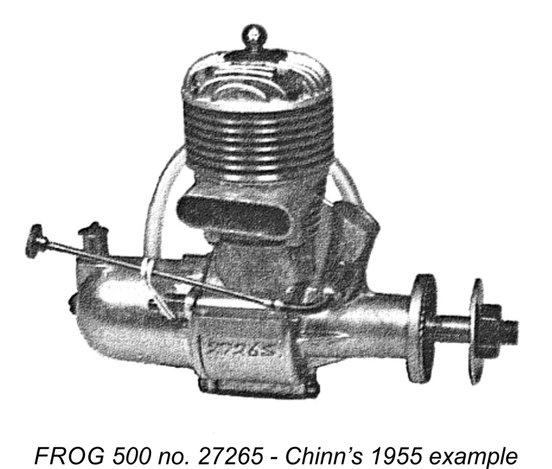
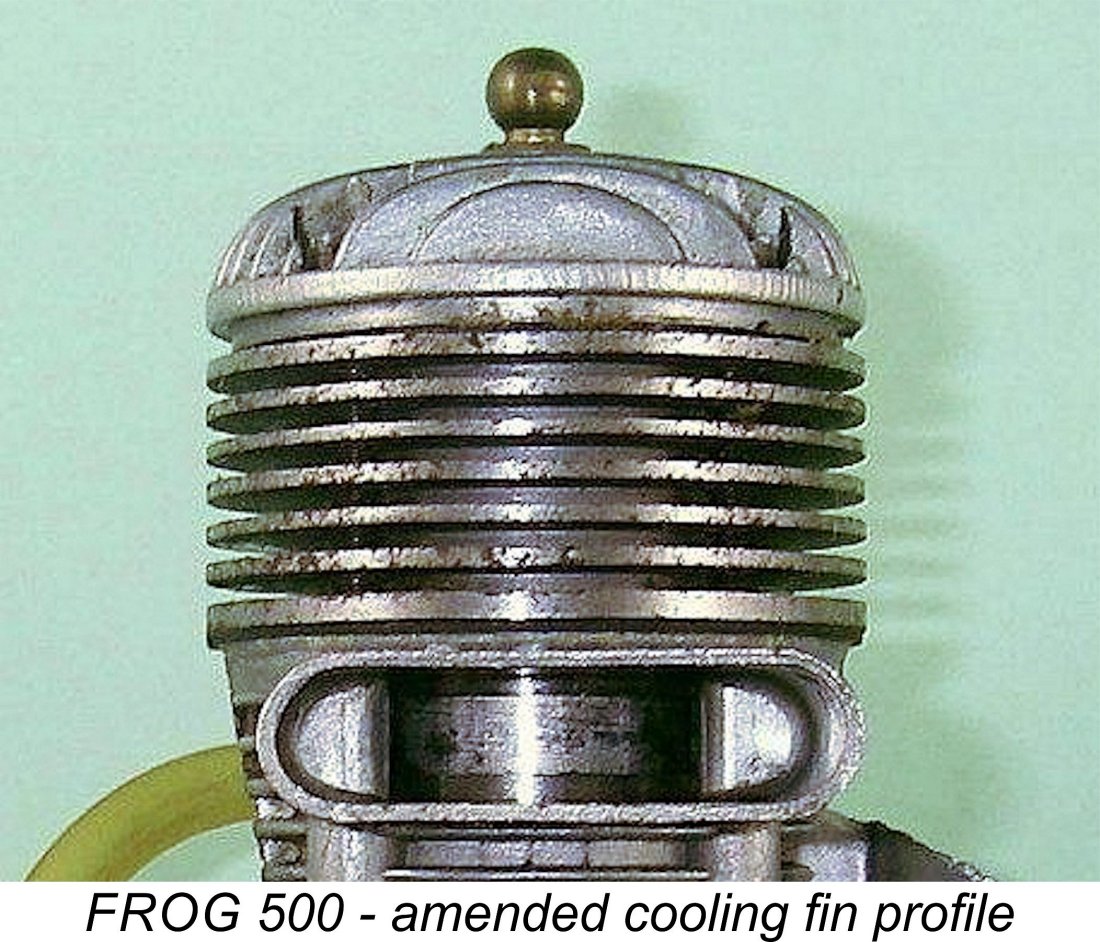 While doing this, they took advantage of the need to change the die to make provision for the eventual addition of a ball thrust race at the rear of the crankshaft. However, they did not actually implement the latter change until mid 1955, starting at around engine number 27000.
 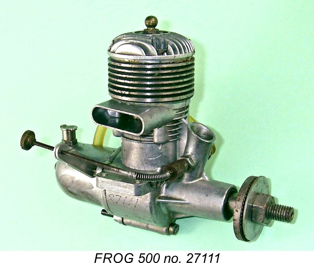 Jon Fletcher and I trawled our respective holdings, finding that all of our thick-lug examples (both complete engines and cases) below engine number 27000 were of this type, right up to Jon’s engine number 26702. However, my own engine number 27111 is of the subsequent type with the ball thrust race, as was Chinn’s engine number 27265. This seems to prove beyond doubt that some 7,000 examples of the second (thick-lug) plain bearing variant were manufactured between mid 1951 and around April 1955 - an average monthly production rate of roughly 150 units. This is a very significant reduction from the 500-550 unit per month average achieved for the original thin-lug model, doubtless reflecting a perfectly understandable decline in demand for the engine in the face of increased competition from the more up-to-date designs then appearing with increasing frequency from competing manufacturers. However, the numbers confirm that some level of demand did still exist.
 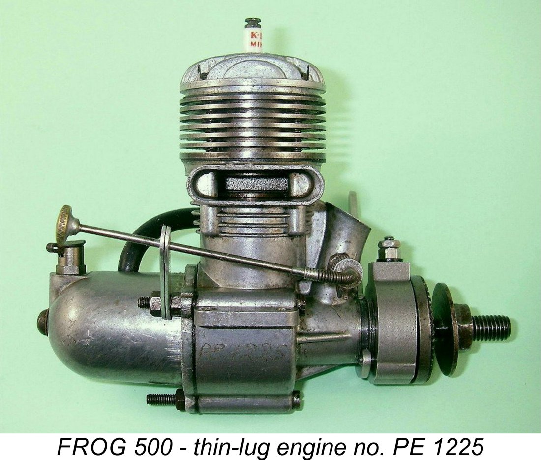 If my own theory regarding seemingly-anomalous thin-lug engine number PE1225 is correct, that example and perhaps a few others like it were likely manufactured at the very end of the PE production program simply to use up a few thin-lug PE cases and timers which had been set aside as spares in 1951. The number of such components is unlikely to have been large. Therefore, engine number PE1225 was probably one of the very last examples of the spark ignition FROG 500 to be manufactured.
 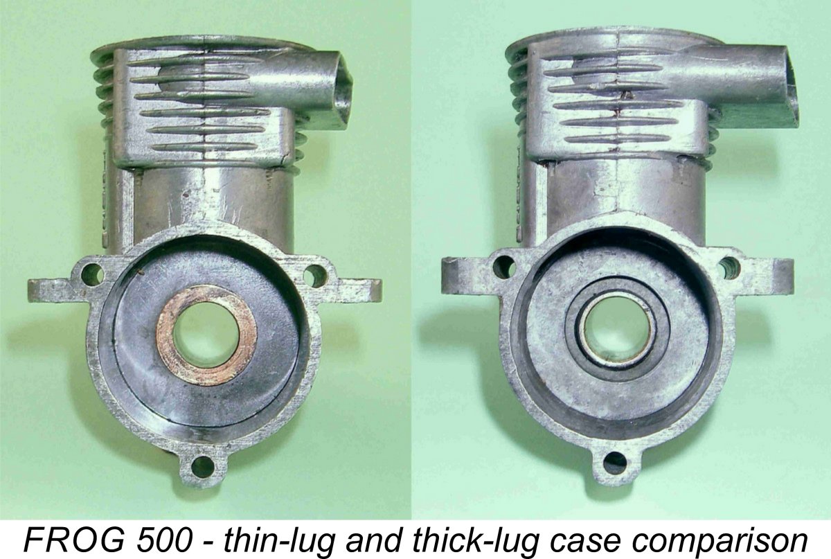 The comparison view of the cases from thin-lug engine number 13131 and thick-lug model 24229 shows very clearly that the cross-sectional area of metal actually attaching the lugs to the main case was essentially unaltered by the increased thickness. All that changed was the thickness of the lugs themselves as well as the arc length of the thin “bridge” of metal at the top of the tank mounting bolt holes - the thickness of the “bridge” remained unaltered. The lugs themselves were certainly stronger, but the inherent weakness imposed by the presence of the holes for the backplate bolts remained essentially unaddressed - all that changed (slightly) was the most probable location for the fracture to be initiated! A far better approach would undoubtedly have been to switch to tapped holes of modest depth at the rear, with short machine screws used as backplate fasteners.
 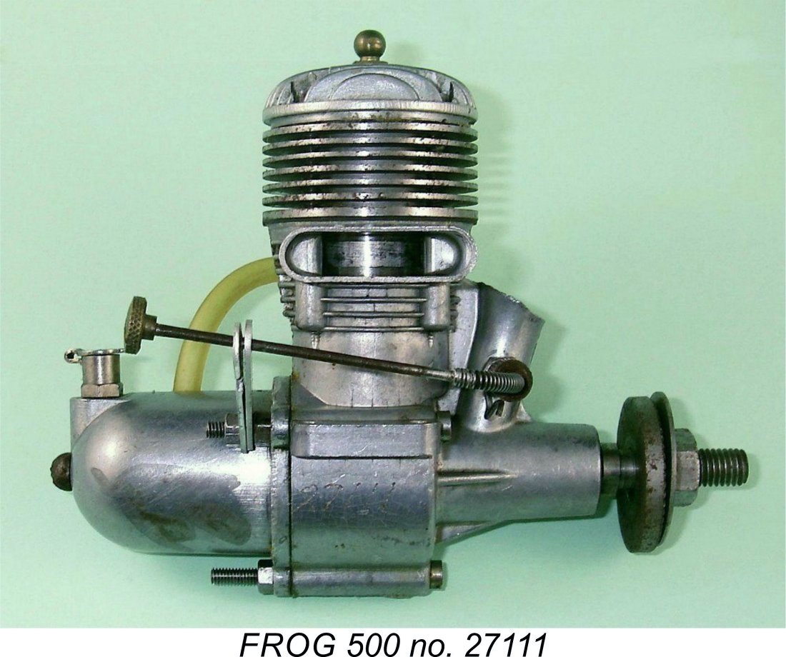 I’ve already discussed the effect which Chinn’s comments had upon the general perception of the number of variants through which the engine had then passed. The article gave the clear impression that all of the described changes had only just been introduced. In fact, as I’ve shown here, the only change which was actually implemented in 1955 was the addition of the ball thrust race for which provision had been made way back in mid 1951 when all of the other changes described by Chinn had in fact been implemented.
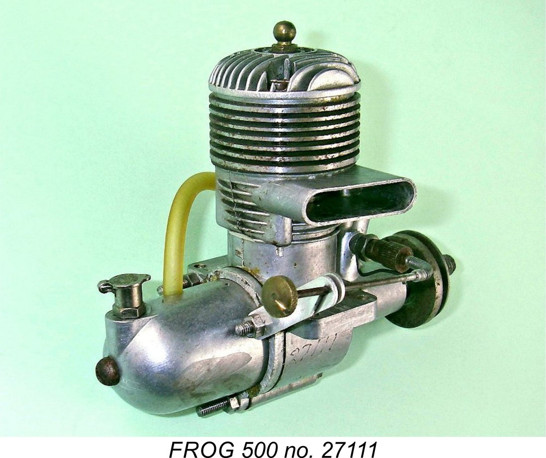
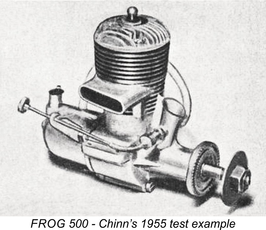 The test report was basically a reiteration of Chinn’s earlier comments on the engine in his two previous test reports. He recorded a somewhat higher output on this occasion, a figure of 0.400 BHP @ 13,000 rpm being reported. However, this result can in no way be compared with those from earlier tests, since on this occasion Chinn was using a fuel containing 28% nitro-propane (an additive having parallel properties to those of nitro-methane, and now known to be a powerful carcinogen which also causes liver and kidney damage). Taking this factor into account, it’s clear that the performance of the engine remained essentially unchanged despite the applied modifications.

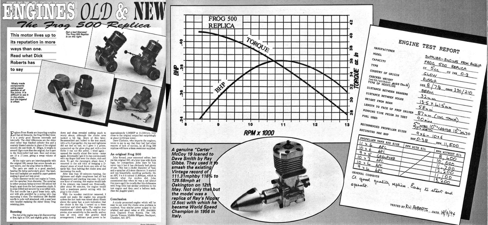
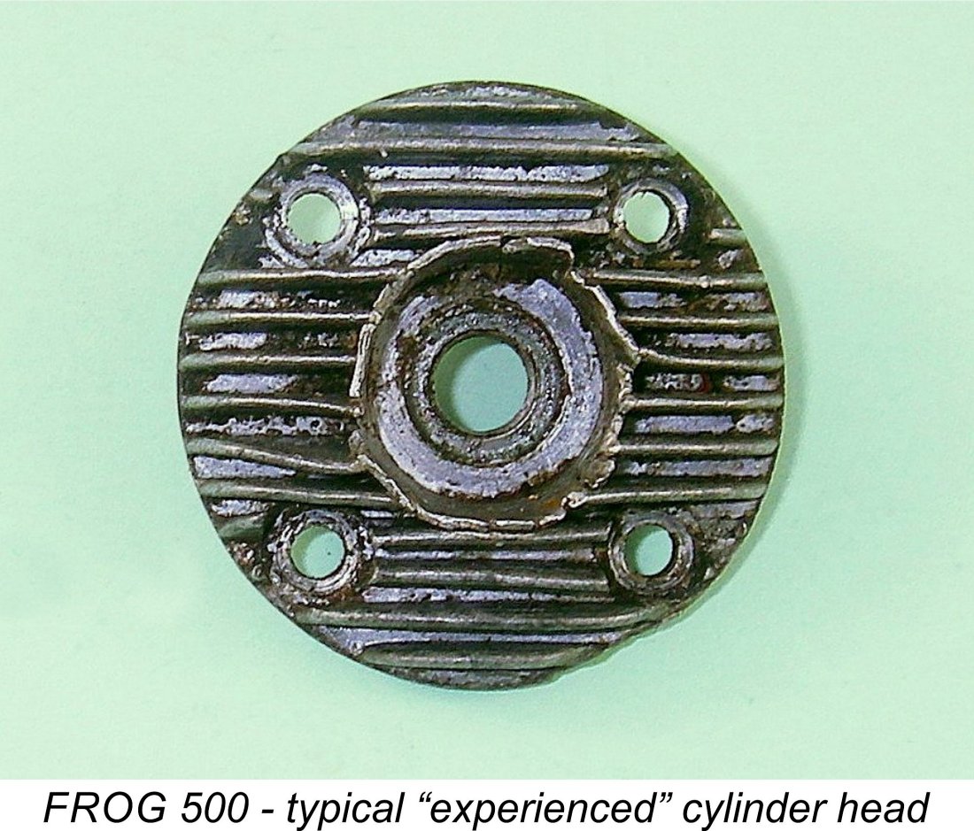 Finally, the vast majority of FROG 500’s that have been used have “expanded” and/or cracked plug recess walls in the cylinder head. This is due to a previous owner’s failure to use a socket wrench which matches the plug and will fit inside the recess provided. The often-attempted use of pliers or an end-on crescent wrench pretty much guarantees such damage. Please avoid further damage, particularly if you have an undamaged example, by using a suitable socket for plug removal! Also, be sure not to over-tighten the plug in the short thread which is all that’s available - the rather poor quality casting alloy used simply won’t take it. A stripped thread can be restored using the appropriate ¼-32 Helicoil kit, but it’s far better (and cheaper!) to avoid having to go that route!
 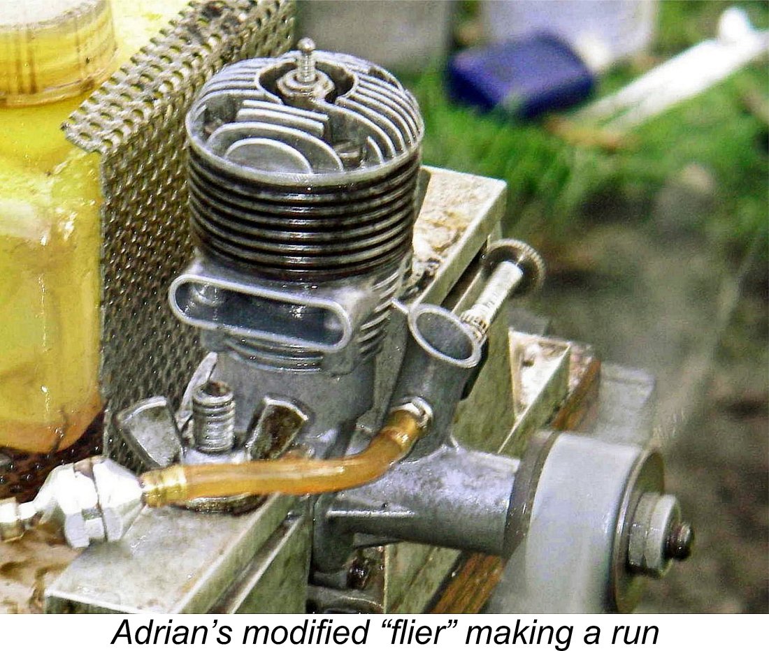 I would never advocate such treatment of a nice example, but if the engine is a really ratty-looking one or if the stack is already damaged, it may be defensible. I’d rather have a few of these engines being used than all of them sitting unseen and silent in a box or on a shelf somewhere!
 | |