
|
|
The Rowell 60 Story
The original text of this article appeared in May 2013 on the late Ron Chernich’s “Model Engine News” (MEN) website, where it may still be perused. However, Ron unfortunately left us in early 2014 without sharing the access codes to his heavily-encrypted site. Since no maintenance of MEN is possible as a result, the site is very slowly but unmistakably deteriorating. I view the Rowell story as too important to risk its loss, hence its re-publication here on my own site. I may as well start right out by making it very clear that my personal claim to any credit for this article is strictly limited! A significant proportion of what follows is synthesized from information published on the outstanding "On the Wire" (OTW) website, which is devoted to tethered hydroplane and car racing, past and present. This is a truly fascinating site which can be highly recommended to modellers in general and model engineers in particular. The primary author of OTW’s extensive material on the Rowell 60 was Lynn Blowers.
I'm deeply grateful to Lynn for her gracious permission to draw upon her earlier work. In addition, I wish to acknowledge the kindness of both Lynn and Hugh Blowers in reading the following text in its original draft form and offering many helpful suggestions and much encouragement. On top of all this, these two fine people and kindred spirits have been most generous in providing a number of the attached images and much of the reference documentation. Without such assistance, this article would have little interest or credibility. Although I have drawn very heavily upon the sources acknowledged above, I have incorporated many of my own comments and observations into the following text as well as reorganizing the material somewhat for my readers. I must therefore stress that any errors or omissions in what follows are entirely my own responsibility. Having clarified and acknowledged my sources, let's look at the background to the introduction of this notable engine. Background
Rail-guided operation was also possible in the case of model cars, but the principle remained the same - the vehicle was constrained to follow a fixed path when running. The attraction of this form of model car racing was the fact that up to 4 cars could race head to head, as seen in the accompanying image. Its downside was the requirement for a costly and complex purpose-built track which necessarily occupied a large area. Tethered operation of model aircraft had its roots prior to WW2 in the form of round-the-pole flying. However, it was not until 1942, when Jim Walker patented his two and three-line U-control systems which allowed full in-flight control of a tethered flying model, that this form of aeromodelling commenced its rapid rise to prominence. Under the name control line, it became immensely popular in Britain and elsewhere during the years immediately following WW2, maintaining this popularity right through to the 1970's. Tethered hydroplane racing was well established in Britain prior to the onset of WW2. Indeed, the first national model boat racing event, the inaugural "Model Engineer Speedboat Competition", was held as early as 1902, the winner's speed being an awe-inspiring 5 mph! Progress thereafter was rapid, and by the mid 1930's speeds were approaching 50 mph using both flash steam and internal combustion (I/C) engines. The sport maintained a steady growth in popularity right up to the onset of WW2 and resumed thereafter, continuing to draw a small but dedicated group of adherents right up to the present day. Speeds of over 135 mph are now being achieved - quite a step up from 1902!
Oddly enough, it was the advent of WW2 that triggered the development of interest in I/C-powered model car racing in Britain. During that unhappy period, the flying of I/C-engined model aircraft was officially banned. Probably a wise move, since any flying model would likely have been shot down by enthusiastic A/A or Home Guard personnel! Regardless, the effect of this prohibition was to ground a sizeable number of perfectly serviceable model aero engines, leaving a group of frustrated power modellers very much open to alternative suggestions for use of these engines.
A set of rules was quickly established to regulate the use of such cars in competition. The ensuing inaugural competition was well supported, the winner being Gerry Buck, whom we shall meet again during the telling of the Rowell story. This and subsequent successes led Russell to go one step further in late 1944 by establishing the British Model Car Club. During this period, British enthusiasts necessarily had to work with chassis, accessories and in some cases engines of their own making, since no such items were commercially available during the war years. However, following the conclusion of hostilities, model car racing experienced a huge upsurge of interest in Britain, with new clubs and tracks appearing almost on a weekly basis. By the late 1940's there were well over 20 active tracks in the British Isles. This activity in turn drew the attention of commercial interests to the hobby, with the result that firms supplying goods related to model car racing quickly began to appear. At the peak of the model car boom in the late 1940's, The 10 cc class was one of the Blue Riband categories in all branches of competitive power modelling, causing several British manufacturers to decide more or less simultaneously in 1948 to enter the field of commercial 10 cc model racing engine production. The North Downs Engineering Company of Whyteleafe in Surrey introduced their Nordec series which included both car and aero versions of their McCoy-inspired 10 cc offering. Ten-Sixty-Six Products Ltd. of Worcester added the 10 cc Conqueror to their already-established range, while our main subject company, Rowell Motors Ltd. of Dundee, Scotland, released the Mk. I version of their Rowell 60 model. In contrast to the Nordec, which was intended all along as a multi-purpose unit, both the Ten-Sixty-Six and Rowell models were designed primarily for model car use.
The instigators of the three competing models mentioned above were by no means alone in promoting the development of large model racing engines in Britain - other
The Z.N. 10 cc model indisputably reached the prototype stage. In his article entitled "Emphasis on the Engine" which appeared in the August 1948 issue of "Model Aircraft", Peter Chinn included a description of the Z.N. 10 cc design in terms which made it absolutely clear that he had actually seen an example. He also briefly mentioning the two smaller models. Sadly, he did not publish any image of the engines. Paul Zere of Z.N. Motors specifically noted that the Z.N. engines were not intended for large-scale series production but were to be individually built and tested to special order. However, the Government decision of April 1948 to apply Purchase Tax to model parts and accessories, including "power units of all kinds", apparently caused Z.N. Motors Ltd. to abandon plans to produce these engines. The model trade fought this decision, but the late 1950 outcome of their legal efforts upheld the Government position, justifying the earlier decision by Z.N. Motors Ltd. A pity - Chinn's comments suggest that the engine would have been a very useful performer. The whereabouts of the one prototype that was evidently completed remain unknown. Ted Martin, chief designer for the Anchor Motor Company of Chester who were the original manufacturers of the AMCO range, also tried unsuccessfully to persuade his employers to sanction the development of a 10 cc AMCO racing engine. In hindsight, given the short production lives of the other British 10 cc racing models, it was almost certainly a wise decision on the part of AMCO management to divert Ted's attention away from large racing engines towards the development of what became his most famous design, the AMCO 3.5 BB diesel. Having set the scene, it's now time to look at the genesis of the Rowell Motors business. Those interested in learning more about the tethered car and hydroplane racing scenes both past and present are strongly recommended to visit the outstanding OTW website to which reference has already been made. Establishment of the Company
Wilf Rowell was a talented hands-on engineer whose technical skills were unusually wide-ranging in scope, extending very much into his hobbies. His personal projects included building 8 mm silent and sound cine-projectors, about which he wrote an article which appeared in the June 1943 issue of “Model Engineer”, going on to publish a book in 1948 entitled "How to Build your own Projector". Some measure of the range of his design and technical skills may be gained from the fact that he also constructed a camera, a full sized Wurlitzer organ and a 9 in. screen television set that he finished just in time to watch the Coronation broadcast in 1953! Wilf was also a skilled model maker. In 1930 at the age of only 15 years he completed a large live steam loco named "Helen of Troy", and in 1951 constructed a smaller-gauge Class V locomotive to run round the garden of his home at Invergowrie, Dundee.
Further research revealed that the actual track was located in the Riverside area of Dundee near the site of the present-day Dundee Airport. Information gathered by Rob Nellies suggests that it was located in the area near the River Tay just to the east of the present-day airport which is now occupied by the University of Dundee playing fields. All traces of the former track seem to have been obliterated by later development.
All of this makes it abundantly clear that, along with his many other interests, Wilf Rowell had by this time become a dyed-in-the-wool model car racing enthusiast. It was presumably this interest which led him to throw his hat into the model racing engine design ring in the summer of 1948. In taking this step, he was doubtless encouraged by a number of his fellow enthusiasts, notably the prominent competitor Gerry Buck, who was a passionate supporter of British-built cars and engines and had actively encouraged Wilf to develop an engine that could challenge the imports. Rowell Production Commences
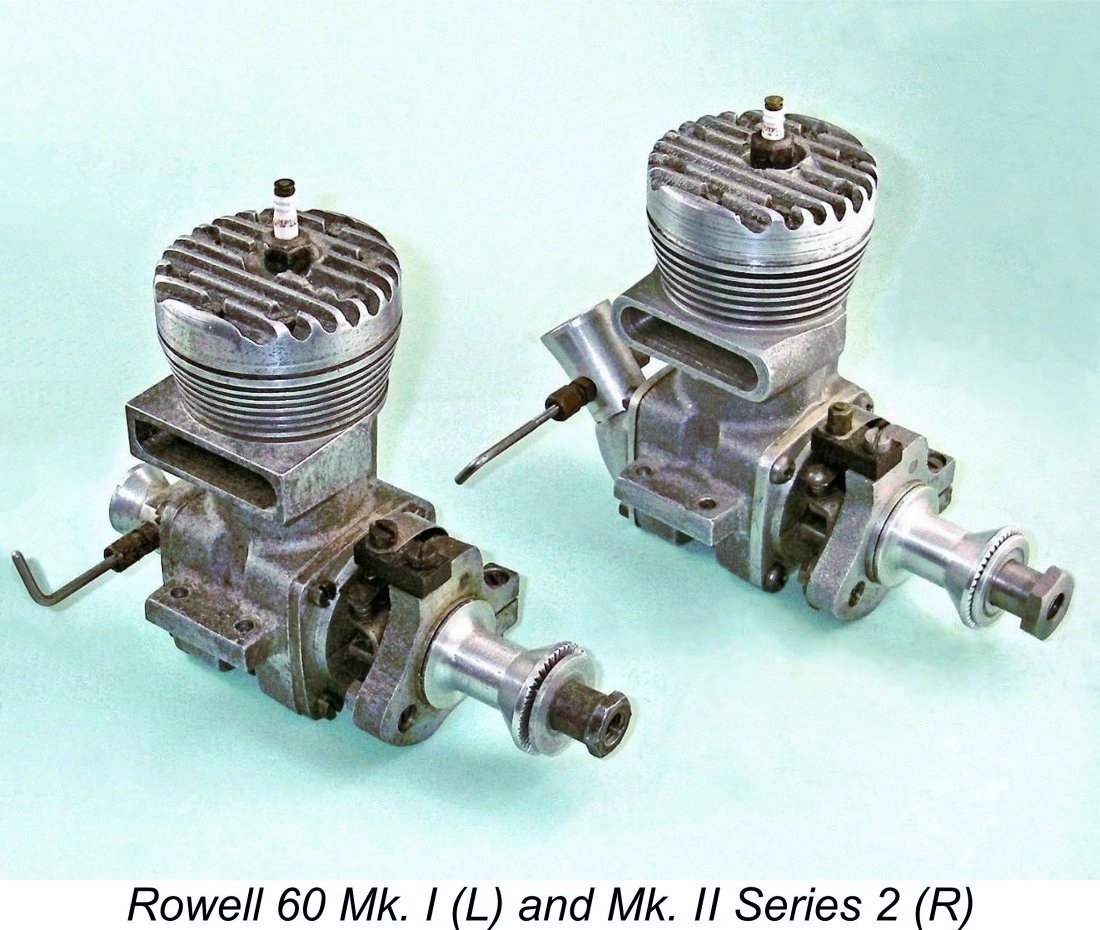
The Mk. I Rowell was most readily distinguishable from the Hornet by the tapered cylinder fins, unusually large-diameter head, one-piece main crankcase casting with detachable front housing and oversized exhaust stack. It actually looked a bit like a Hornet that needed to go on a diet! With RRV induction through a Hornet-influenced venturi and a sturdy ignition timer using The Rowell 60 was advertised as being available from Rowell Motors at 93 Victoria Road, By 1948 standards, the Rowell 60 was very far from cheap. The price quoted in the brochure for the standard spark ignition engine, complete with K.L.G. plug, was a whopping £12 10s 0d (£12.50) - a small fortune in those far-off days in early post-war Britain when a person earning £8 a week before taxes would have been considered quite well-off! The engine was offered in glow-plug configuration as well, albeit at the same price. However, the price of the engine was only the beginning! If you wanted to use the engine in a model aircraft application, you had to pay an extra 7s 6d (38p) for a prop driver like that fitted to the illustrated example. A marine flywheel and universal coupling for hydroplane use added £1 2s 6d (£1.13) to the basic price of the engine. Worse yet, use of the engine in model car service required a further outlay of £3 for a flywheel and centrifugal clutch. Half a month's pre-tax salary for one model engine - pretty steep! And then you still had to get a car together for the engine to power ………at a cost which likely exceeded that of the engine!
Quite apart from the engines themselves, the ever-increasing list of chassis and drive train components offered to the car racing fraternity under the Rowell name raises the question of where all these products were made. The manufacturing certainly did not take place at Brian Sherriff's model shop at 93 Victoria Road, Dundee. In fact, it's probable that Rowell Motors never had their own manufacturing facility, instead contracting out most if not all of their manufacturing to others. The production figures for the engines and accessories were certainly low enough for this to have been a perfectly rational proposition. A considerable body of evidence points towards the involvement of at least two local companies in the production of components for Rowell Motors. These were the Arbroath Tool and Gear Company, who may have manufactured the gearbox components and other precision parts for Rowell, and Kingdom Models at the evocatively-named Coaltown of Wemyss in Fife, who built the very well-made 1 cc Clan diesel motor (reportedly in a converted cowshed!) and may well have been involved in the manufacture of the Rowell 60 engines in addition. Lynn Blowers’ OTW article on Rowell informs us that "a thrifty Scotsman who cycled to Coaltown of Wemyss to buy a Clan engine direct from Kingdom Models (thus cutting out the middleman!) reported seeing a number of Rowell engines whilst he was there."
However, my valued Scots mate Don Imrie has uncovered persuasive evidence to suggest that the manufacturing of the Clan and Rowell engines was transferred at some relatively early date to a larger existing facility known as the Claymore Works located at nearby Thornton. Amazingly enough, portions of this facility still survived as of 2022, albeit in a derelict state. The lintel of the green door of the former office complex (left in the accompanying photo) The identification of this derelict facility as a former model engine manufacturing location is supported by the recollections of one of Don Imrie's older club-mates, who did some electrical work there when it was still in operation. He recalled seeing a number of model engine components being handled. He wasn't able to positively identify these, but both Clan and Rowell components are distinct possibilities. A long-time adjacent resident also supported this identification, stating that to his personal knowledge a variety of "model stuff" was manufactured there during the early post-WW2 period. I've discussed this matter more fully in my companion article on the Clan engines. Wherever the engines were made, it's almost certain that they were individually constructed rather than being assembled on a production line. The number of minor variations between examples makes this abundantly clear. A case in point is the configuration of the driving end of the crankshaft. Hugh Blowers reports that examples have been encountered with threads of 1/4 BSF, 5/16 BSF (as on my own two examples) and 5/16 UNC! Moreover, the flywheel-prop driver attachment varies between taper-on-shaft, split collet and taper/grubscrew systems!
The engines carried a thirty-day warranty against defects encountered during normal operation. Failures due to accidents involving any model in which the engines were installed were specifically not covered, nor were problems caused by tampering with the unit. Reading the fine print, one may suspect that few of these guarantee cards were actually registered since the registration portion of the guarantee card had to be returned to Rowell Motors within three days of the purchase date! It may be doubted that many modellers managed to comply with this requirement even if they tried to do so! By 1949 Rowell Motors had become a limited company. The directors were Brian Sherriff, Wilfred Rowell and one T. Scott. The respective roles of these individuals are not completely clear. Brian Sherriff evidently had the trade contacts and the marketing premises, while Wilf was obviously the designer and motivator. The part played by the elusive T. Scott is unknown. However, the scale of the company's activities makes it clear that a sizable financial commitment would have been required from some external source. It's possible that Scott was the money behind the venture. The Rowell 60 Mk. I Described
Nominal bore and stroke were 0.940 in. and 0.875 in. respectively for a displacement of 0.607 cu. in (9.95 cc), exactly the same on all counts as both the McCoy and the Hornet (and the Nordec, for that matter). However, the Rowell was far more massively constructed than either of its American rivals, hence being both bulkier and heavier. It weighed all of 546 gm (19.25 ounces) with plug and timer but minus flywheel - well in excess of any of its competitors. It was of course intended primarily for car use, but even so this figure seems somewhat excessive. That said, a stiff structure is a well-demonstrated aid to dependable high performance.
It’s likely for this reason that the name of the engine is conspicuously absent from the results of control line speed contests held during the period when it was in production. It did find such applications, although the only published record of any contest success that I can find is a top three placing in the 10 cc speed category at the South East Area Control Line Championship meeting held at Dover on Easter Weekend of 1949 (“Aeromodeller”, June 1949). To put this in perspective, it should be noted that the winning speed at this meeting fell slightly short of the 100 mph mark! The Brits had a long way to go in the control-line speed field! That said, I retain some very clear recollections of my personal teenage encounters with a heavily modified Rowell 60 (a Mk. II to the best of my recollection) running on glow-plug ignition which was still powering a control-line speed model in the hands of one of my club-mates in Sheffield, Yorkshire around 1961. I In keeping with established large racing engine practise, the crankcase, front and rear housings, timer frame and cylinder head of the Rowell 60 were all sand-cast in a high-grade aluminium casting alloy which was subsequently heat-treated. Although the finish of some of the early castings was a bit on the rough side, the engines were machined to very high standards, A great deal of design effort was clearly put into reducing crankcase volume in order to improve the engine's pumping efficiency. This extended to the use of a bypass passage which, like most others of the period, was rather on the small side, a feature which it shared with the Nordec and Ten-Sixty-Six opposition. This was likely due to the influence of the contemporary versions of the Hornet and McCoy engines, both of which also had somewhat undersized bypasses. McCoy were very shortly to address this issue later in 1948 with the introduction of the vastly-improved Series 20 A feature of the Rowell which was seemingly intended to further reduce crankcase volume The con-rod actually operated though a slot cut through these wedges. This slot is best seen in the previously-reproduced component image of the engine. The effect of this approach was to reduce crankcase volume by the space occupied by the residual metallic intrusions, at the cost of somewhat restricting gas access to the bypass passage. This arrangement precisely mirrored that seen in the design of the Hornet 60. The porting of the engine was quite conventional by contemporary racing engine standards. The basically rectangular exhaust port was divided into 6 segments by narrow pillars intended to prevent ring snag. The transfer port was similarly divided into only three segments. Once again, both of these features precisely reflected the design of the Hornet 60. The lower entry to the bypass passage was extremely restricted in size. The presence of the previously-mentioned metallic intrusions left behind after machining didn't help in this regard either. To compensate for this, the transfer process was assisted by the presence of additional porting in the liner on the transfer side below transfer port level which corresponded at bottom dead centre with similar ports in the piston skirt. In addition to enhancing transfer efficiency by improving gas access to the bypass passage, the piston ports also encouraged improved piston cooling and lubrication by promoting the flow of cool incoming mixture through the piston interior. In terms of the engine's breathing capacity, such ports were very necessary in the Rowell design, just as they were with the Hornet. The Rowell piston looked in fact very much like its Hornet counterpart - even the rings are interchangeable.
The appearance of illustrations of the Rowell 60 featuring the oval port both in Lawrence Sparey's July 1949 “Model Cars” test report (see below) and in a May 1950 “Model Engineer” article on engine maintenance by G. W. Arthur-Brand seems to prove that this was a factory variant as opposed to an owner modification. This appears to be a further example of the individual approach taken to the construction of each engine.
The light alloy rear disc valve of the Mk. I Rowell was timed somewhat more conservatively than that of either the Conqueror or the Nordec R10, remaining open for some 170 degrees as compared to the 190 degrees of the Nordec and the even more aggressive 195 degrees of my own Ten-Sixty-Six model (which may well have been modified by an owner). The disc was bronze-bushed at the centre to provide a hard-wearing bearing surface. The steel mounting spindle had a working journal diameter of a nominal ¼ in., which extended part-way through the backplate. The balance of the spindle was stepped down to a 4BA threaded length which engaged with a similar thread in the backplate. Once assembled, the spindle was secured by a lock-nut placed on the protruding spindle thread at the rear.
The combustion chamber was more or less orthodox, with the piston sporting a McCoy-style high-domed baffle and the head having a matching contour. The plug was offset towards the transfer side, presumably to speed up the involvement in the combustion process of the isolated pocket of gas behind the piston baffle at top dead centre. The head was secured by no fewer than eight slot-head screws. The compression ratio of the Rowell was cited as 12:1 - very high for the period, but no doubt tailored to the use of a methanol- The owner was evidently expected to run the engine on a methanol/castor oil mixture, a fuel which was also specified for the Ten-Sixty-Six Conqueror with its even higher 13:1 compression ratio. You certainly wouldn't want to run engines having such high compression ratios on regular gasoline! Nitromethane was virtually unobtainable in Britain at the time, as well as being prohibitively expensive when it was available. Accordingly, its use in significant proportions would not be anticipated - otherwise, a somewhat lower compression ratio would likely have been employed. Even so, the manufacturers of the Rowell did note on the instruction sheet that a higher performance could be obtained through the addition of nitromethane to the fuel. As previously noted, the Rowell was offered in glow-plug configuration as well as in spark ignition form, although there seem to have been very few takers for the glow-plug version. I must admit that I would be rather hesitant to run this engine for any length of time at anything other than relatively high speeds while leaned out on glow-plug ignition, especially on a high-nitro fuel. This is because glow-plug ignition timing at a given plug element temperature is mainly dictated by compression ratio. Plug element temperature in turn is heavily influenced by mixture strength - a lean mixture creates a higher element temperature regardless of operating speed. As a result, pre-ignition when leaned out using a 12:1 compression ratio would likely be a factor until relatively high speeds were reached. Accordingly, the engine is probably best operated on spark ignition. Indeed, the absence of any presently-known surviving purpose-built glow-plug examples suggests that it was more or less universally operated in spark ignition mode, at least during its heyday. It would have made very good sense to equip the glow- Another feature which gives rise to potential operating problems is the complete absence of any form of knurling on the driving face of the bobbin prop driver, at least on my example as received. A high-torque engine of this displacement having such a high compression ratio undoubtedly requires some form of positive prop/driver keying system, if only for safety reasons. I found by direct experiment that even flipping a prop over against the very high compression was enough to cause the prop to slip unless it was tightened to what I'd consider a drastic degree. This was especially true once a trace of oil got into the prop-driver interface, as it almost inevitably will during operation. Since I planned to test-run my example using an airscrew, I first tried installing a pair of 5 BA studs in the face of the prop driver, creating matching 1/8 inch holes in the rear of the prop. I've seen a similar provision applied to several examples of the Nordec RG10, and that engine had striations on the driving I've little doubt that anyone planning to use a Rowell in aircraft service would have taken steps to improve the interlocking between the prop and driver. In fact, Hugh Blowers informs me that some (but not all) examples did have spiral knurling on the driving face of their prop drivers. It's a matter for wonder that all did not do so - it's certainly not safe to try running a Rowell on an airscrew without some measures of this kind. Be warned!
A final oddity worth noting is the fact that the assembly screw threads used in many examples of the Rowell 60 are BSW rather than BA. My own two examples both use 1/8-40 BSW head-screws and 5/32-32 BSW front and rear cover screws. This is rather unusual for a British engine of the period, suggesting that the use of such threads was dictated by the fact that this was what was available at the manufacturing facility! This highlights a not-uncommon facet of early post-war British model engine production - materials and fasteners were scarce, forcing manufacturers to use whatever they had on hand at any given time. This actually resulted at times in different examples of the same model having different assembly threads. The Rowell 60 Mk I on Test
The Rowell 60 Mk. I was among the engines which was subjected to Sparey's attentions. It was in fact the second British racing engine to be tested by him, the first having been the Nordec RG10. Sparey's test of the glow-plug Nordec had appeared in the March 1949 issue of “Aeromodeller” magazine. It was in fact Sparey's first-ever test of a glow-plug model engine. Given the fact that the Rowell was specifically designed for model car racing, Sparey's test of that model did not appear in “Aeromodeller”. Instead, it was published in the July 1949 issue of “Model Cars” as number 2 in a series of tests on what Sparey termed "High Speed Engines". Sparey's test of the multi-purpose Nordec R10 spark ignition model had appeared in the April 1949 issue of “Model Cars” as number 1 of that series. The published “Model Cars” test of the Nordec R10 seems to have set the red lights flashing in Wilf Rowell’s mind. He had evidently sent an example of the Rowell 60 Mk. I to Sparey for testing purposes. In Rowell’s view, Sparey’s published test of the competing Nordec model was flawed in several respects. He was clearly anxious to ensure that the same flaws didn’t appear in the forthcoming test of the Rowell 60. In a published letter to “Model Cars” magazine dated May 3rd, 1949 which is reproduced here, Rowell laid out several points which he asked the magazine staff to pass along to Sparey to inform his test of the Rowell 60. In his report on the Nordec, Sparey had commented upon what he considered to be a typical characteristic of ringed-piston racing engines, namely “poor compression when cold”. Sparey had commented upon what he saw as the erratic running of the Nordec when operated on a flywheel without load. Wilf Rowell commented that this was to be expected and hence should not be read as a criticism. The carburettors of such engines were logically stated to be designed to perform extremely well when running under load, which is after all what they were intended to do. Rowell pointed out that even the fabled Dooling 61 ran erratically with no load applied. Running a racing engine on an unloaded flywheel - not a recipe for longevity! Finally, although the test example sent to Sparey was a spark ignition model, Rowell was clearly very anxious to ensure that Sparey tried the Rowell 60 on glow-plug ignition. He referred to some very successful tests which he and his colleagues had been conducting using this form of ignition, claiming that they had reached 88 MPH on straight methanol/castor fuel. A number of cars competing in his area were said to be in the process of conversion to glow-plug operation. He stated directly that “it would be nice if Mr. Sparey could try out the engine with a glow-plug”. In light of these very supportive comments from the designer, the fact that no purpose-built glow-plug examples of the Rowell 60 are currently known to survive seems really odd ................ Wilf Rowell’s letter evidently had its effect, because Sparey’s subsequent published report on the Rowell 60 made no mention of any issues with the sealing qualities of the rings, nor did it mention any erratic running when not under load. In addition, it did include some data obtained using glow-plug ignition. Sparey's report on the Rowell was generally very complimentary as regards its handling and performance. Once he had established a starting procedure which accommodated the flooding-prone gravity fuel feed system employed, he stated that he "could not speak too highly of its handling qualities". As prompted by Wilf Rowell’s earlier letter, Sparey took advantage of the opportunity to make a direct comparison of the engine's performance both on spark and glow-plug ignition. On spark ignition, running was said to be "perfect at all speeds". On glow-plug ignition, running was reported to be "equally good" apart from a tendency to misfire "at speeds below 6,000 rpm"(!!). This latter comment highlights Sparey's chief failing as an engine tester - his mind seemed unable to keep pace with emerging engine design trends and technologies. In particular, he clearly failed to grasp the fact that leaned-out glow-plug ignition timing is fixed to within relatively narrow limits by a combination of compression ratio, fuel mixture composition and plug heat range with its associated element temperature. While the effect of engine speed on element temperature certainly plays a role in establishing the timing, it has far less primary influence than the other three factors. Consequently, the timing of a glow-plug engine having a set compression ratio and using a given fuel composition and plug is relatively (although not of course completely) independent of the engine speed when fully leaned out, and the operator can do little to change it apart from either richening the mixture, thereby sacrificing power, or using a colder plug and/or a less "hot" fuel. The only way to keep such an engine happy is to run it at or near the speed at which the various factors combine to optimize the leaned-out ignition timing. Put another way, you have to select a load which yields an operating speed matching the engine's built-in ignition timing. The timing of the Rowell when leaned-out on glow-plug ignition with its 12:1 compression ratio was guaranteed to be well advanced regardless of operating speed. This would be OK and even desirable at high speeds, but any attempt to operate the engine leaned out at speeds significantly below its design operating range would inevitably produce pre-ignition and elevated internal stresses. The concept of operating a Rowell 60 leaned out at below 6,000 rpm under load on glow-plug ignition gives one the shivers……...! Sparey had actually treated the poor old Nordec RG10 even more harshly in his “Aeromodeller” test, loading it down to 3,800 RPM on glow-plug ignition……………ouch!!
Sparey completed his test of the Rowell 60 on spark ignition, finding a peak output of 0.732 BHP @ 13,900 RPM using straight methanol fuel with 30% castor oil. Perhaps due to the use of straight fuel with no additives, this was some way below the figures claimed by the makers and was also considerably less than later testing has implied for the Rowell. Sparey's testing procedures may also have had a bearing on this issue. Even so, the reported numbers significantly topped the figures of 0.48 BHP @ 11,200 rpm which had been reported by Sparey in March 1949 for the rival Nordec RG10 model on glow-plug ignition using a straight 75-25 methanol/castor fuel mix. Peter Chinn's figures of just over 0.74 BHP @ 12,500 RPM ("Model Aircraft", June 1949) for the Nordec R10 running on spark ignition were probably more representative of the Nordec's true capabilities, but there's no question that the Rowell far outperformed its English rival. Sparey's subsequent tests of the Rowell using glow-plug ignition were commenced using standard Mercury glow-plug fuel, probably the recently-introduced Mercury no. 5. In this form the engine was found to deliver marginally less power at a given speed than it had managed on spark ignition, at least at the speeds previously tested using spark ignition. This is almost certainly a reflection of over-advanced ignition timing at the lower speeds on glow-plug. However, as speeds passed the point at which the peak on spark ignition was reached, the output on glow-plug was found to be still climbing, with no sign of a peak being reached. Sparey actually commented that the engine seemed "much more lively" on glow-plug ignition, thus endorsing Wilf Rowell’s previously-stated opinion. Unfortunately, Sparey was unable to report just how much more lively, because as speed reached 14,400 rpm with power still rising steadily, the mounting spindle for the rotary valve disc sheared at the point where it was stepped down to the 4BA installation thread, rendering the valve inoperative and stopping the Interestingly enough, during initial testing my own example of the Rowell 60 Mk. I suffered an identical failure to that experienced by Sparey, fortunately again without significant damage to the rest of the engine. An identical replacement was easily made. It's clear that there was a fundamental design weakness in the rotor mounting system adopted. Sparey suggested that the 4BA thread by which the rotor mounting spigot was secured could with advantage have been made 2BA. This advice actually makes a lot of sense. The use of a left hand thread would also have been a wise provision against the possibility of the spindle becoming loose and unscrewing during operation. I used low-strength Loctite on the retaining nut when installing my replacement spindle. I would advise other owners to follow suit. A far later test of a Mk. I Rowell 60 bearing the serial number 150 appeared in the June 2008 issue of "SAM Speaks". The complete text of this test report may be found in the main Rowell article on the OTW website.
Dick's initial test runs were undertaken on glow-plug ignition to facilitate the establishment of a needle setting. Using a 12x6 APC airscrew, the engine hand-started quite easily on a straight 80/20 methanol/oil mix and responded well to the needle. Further runs were undertaken using spark ignition and an electric starter (try hand-starting a large fixed-timing racing sparkie!). In this form, the engine ran even better, with improved needle response. Dick found that running qualities were excellent, vibration in particular being notably absent. This was no doubt due in large part to the previously-noted attention paid to the counterbalancing of the engine as well as its higher-than-average weight. Everything stayed tight - even the mounting bolts needed only a minor tweak after a few runs, while no leaks developed anywhere. Dick tried the engine on two different props, recording 10,560 RPM on the 12x6 APC (equivalent to around 0.97 BHP), and 11,780 RPM on an 11x6 APC (around 0.96 BHP). Since the indicated output at the higher In fact, these are remarkably good figures for 1948, beating the original Nordec R10 by a mile and coming very close to the reported output of the illustrated 1946-48 black-case McCoy 60 upon which the Rowell was based in large part. However, that version of the McCoy was almost immediately replaced by the Series 20 version which produced some 50% more power at far higher revs. So in real terms, the contest between the McCoy and the Rowell was over before it had begun .......... and when it came to the Dooling, the Rowell was never in it apart from its superior durability. I've tried my own example on the bench using glow-plug ignition, keeping it on the rich side for the most part as well as using a low-nitro fuel containing 30% castor oil. The revised prop driver with its knurled front face performed well, and I had no further prop troubles. I started out trying an 11x6 APC prop, but actually found that the engine seemed happier at the somewhat higher speed permitted through the use of a 10½x6 APC prop. This prop seemed to suit the engine very well indeed, and I feel comfortable in recommending its use to any other Rowell owner who may wish to give his engine a run or two.
Fuel draw is more than adequate for operation on suction feed - I'm at a loss to understand why Sparey needed to use gravity feed with its associated potential for crankcase flooding during starting. I can also endorse Dick Robert's statement that vibration levels are remarkably low, especially for such a large engine. After some 20 minutes of rich running to settle things down, I did try leaning the engine out very briefly, using an extremely cold plug with an oily 10% nitro fuel. In this state, I actually did a little better than Dick, probably due to the 10% nitro in the fuel that I used as compared to the straight fuel used by Dick. I saw 12,000 RPM on the 11x6 prop and 13,300 on the 10½x6, with very smooth running in both cases. This is actually quite impressive - Hornet 60 no. V197 tested at the same session using the same fuel and props only managed 12,200 RPM and 13,600 RPM respectively. Based on established power absorption coefficients for the props in question, the implied power outputs for the Rowell at the two speeds achieved are 0.98 BHP and 1.09 BHP respectively. These figures certainly appear consistent with factory performance claims, although the implied output falls well short of the levels then being achieved by the Dooling 61 and the Series 20 McCoy 60 which had been introduced more or less concurrently with the Rowell. The "bulge bypass" Hornet update which appeared in 1949 also handsomely beat these figures, although it too was no match for the Dooling or McCoy. Further Development of the Rowell Range
Due in large part to its comparative availability, the Rowell 60 quickly achieved a position of considerable prominence in the British model car racing world. The April 1949 issue of “Model Cars” carried the attached front page picture of W. (Bill) Armstrong of Dundee with his Rowell-powered bevel-geared Demon. The associated write-up noted that the car had reached 86 mph despite the fact that the chassis had In 1949 the company published a 40-page booklet entitled "Miniature Race Cars, their Design and Construction" priced at 2 shillings (10p). In addition to providing detailed information about all aspects of building and running a tethered model car, the booklet showcased the extensive range of products being offered at this time by Rowell Motors Ltd. Oddly enough, the cars illustrated included the Hellcat and Bill Armstrong's Demon which it was claimed were designed and built by Rowell Motors despite the fact that they both incorporated a significant number of components actually manufactured by Z. N. Motors of Willesden in London. An interesting statement appeared in the introduction. This read: "... in order to provide high speed, we are compelled to offer designs and information for building cars on the American lines". More or less an open admission of the superiority of the very functional American approach as well as an apology for riding on the coat-tails of the Americans rather than ploughing their own furrow!
All the items on offer were branded as Rowell "products", even though most or all of them were in reality produced by others. The list included the Rowell 60 Mk. 1 engine with spark ignition at a slightly reduced price of £12 even, or £11 10s 0d (£11.50) in glow-plug configuration. The complete absence of known survivors of the latter model implies that few if any were in fact sold. This is rather odd considering Wilf Rowell’s strong endorsement of glow-plug ignition in his previously-cited letter. It appears that owners generally settled for operating their spark ignition units on glow-plug ignition rather than purchasing a purpose-built glow-plug model. Also available were an American pattern bevel gearbox, spur gear drive unit, centrifugal clutch, "Hot Spark" ignition coil, direct-drive flywheels and gears and a Rowell-Barnard 4 volt accumulator. The Rowell wheels and tyres were offered in both driving and knife-edge configuration, being almost identical to the American Dooling designs. A range of components for the Rapier car completed the list. As the most powerful commercial British-made engine at the time, interest in the Rowell 60 was by no means confined to the engine testers of the day. Edgar T. Westbury commented upon it in an article, and the Rowell also appeared in both Col. C. E. Bowden's 1949 book "Model Glow Plug Engines" and the 1949 "Model Car Manual" by “Model Cars” Editor G. H. Deason. The "MCN Grand Prix Special" was designed around the Rowell, while the write-up for the "Stubbs Austin"' published in Deason's "Model Car Manual" suggested the motor as being suitable for high performance applications. In addition, G. W. Arthur-Brand joined Lawrence H. Sparey in putting it under the microscope in a published bench-test report. Minor problems were identified, but overall the Rowell 60 received very favorable reviews which doubtless provided very good publicity.
Warring's data showed the Rowell to be some 3 oz. heavier than the Hornet or Dooling and almost 4 oz. heavier than the McCoy and Nordec. This was bad enough, but an even wider gulf was revealed when the power outputs were considered. While the Rowell handily outperformed the original Nordec, the leading American motors showed themselves to be Although Wilf Rowell openly disputed some points in Sparey's previously-cited “Model Cars” test of his engine, it's clear that he took the underlying message to heart. This was that the latest American models performed at significantly higher levels than the Mk. I version of the Rowell 60, making further development essential if Rowell wished to remain in the game. The direct consequence of this realization was the early 1950 announcement that a new Rowell 60 Mk. II design would be ready in March at the significantly reduced price of £9 17s 6d (£9.88). The Rowell 60 Mk. II Series 1
The other immediately obvious alteration was a new die-cast back-plate featuring both a down-draught venturi set at around 35 degrees from the horizontal and a far longer disc bearing. The piston design was also revised, now being produced by die-casting as well. The use of die-casting for these components implied that more advanced foundry techniques or perhaps even a different producer were now involved. Internally, the new model featured changes to the head and cylinder liner to go along with the re-designed crankcase, intake and piston. These revisions were claimed by the manufacturer to have raised power output to 1.25 BHP, more or less matching the output of the much-improved Nordec Special Series 2 which appeared in prototype form at more or less the same time but never seems to have made it into series production. However, these figures still fell well short of the measured performances achieved by the contemporary McCoy 60 Series 20 and Dooling 61 models.
So far so good, but the development of the Rowell 60 did not stop there. It appears that the original Mk. II version of the engine remained in production for only a few months, since the June 1950 issue of "Model Engineer" carried an article written by Wilf Rowell on the subject of ignition systems which featured a new Rowell car design, the Sabre. This design More significantly from the standpoint of our present interest, the engine in the illustrated example of this car appeared to be the final version of the Rowell 60, the Mk. II Series 2. Let's examine that model next. Final Fling - the Rowell 60 Mk. II Series 2
It's possible that the engine was originally completed in its timer-less form - we simply don't know. However, thanks to the kindness of my good friend Miles Patience I was able to acquire an original Rowell timer assembly to complete the engine in spark ignition form as illustrated. As received, the engine also lacked any prop mounting components, presumably because it was intended for car applications. The set-up seen in the images consists of my own replicas of the components used on my example of the Mk. I model. In addition, at some point in its life the lower edge of the backplate mounting flange had sustained damage of some kind. This had been Somewhat unusually, the engine displays no serial number. Such an omission is normally due to dressing of the outer ends of the mounting lugs, but this example shows no evidence of this, actually retaining traces of the original milling marks on the ends of the lugs. The surfaces appear to have been smoothed with a piece of emery cloth, but nothing more. Given the above observations, I'm in agreement with Hugh and Lynn Blowers that this example of the engine was most likely assembled after series production had ceased. It's known that considerable quantities of finished parts remained on hand when the company ended its manufacturing activities, and it seems likely that this engine was built up later from a set of left-over components, thus explaining the absence of a factory serial number. Other un-numbered examples of the Rowell 60 have been reported, raising the possibility that more than one engine was assembled after the fact in this manner. If this is indeed how this engine came to be constructed, it's entirely possible that no timers remained on hand. Alternatively, the intention from the outset may have been to operate the engine in glow-plug mode. Either way, the absence of the timer would be explained. Another possibility associated with this scenario is that the only remaining Series 2 backplate casting was one which was flawed during the casting process and had been rejected. This would explain the need for the weld repair to the backplate, which is otherwise difficult to account for - how do you break a backplate mounting flange?
The revised model was even heavier than the original Mk. I variant. Weight of my own example as illustrated with plug and timer is 557 gm (19.65 ounces), some 11 gm more than that of the Mk. I. The heavier backplate and oversized induction arrangements probably account for most of the increase. Apart from the revised crankcase and backplate castings, an examination of my own example of the Mk. II Series 2 model during the course of a precautionary rebuild has revealed a number of significant departures from the design of the Mk. I model. Beginning at the venturi intake, the throat of this component now has a monumental diameter of 0.410 inches (10.41 mm). This would logically be expected to impose a requirement for the provision of either pressure or gravity fuel feed. The fact that this diameter is more or less identical to that used in the trend-setting McCoy 60 Series 20 is probably not coincidental .........
The most important of these was the fact that space considerations made it impossible to accommodate a near-horizontal or shallow-angled intake venturi of the size now proposed alongside the extended disc valve bearing. The upward angling of the venturi kept it completely clear of the The second advantage was that the revised intake orientation permitted the intake register in the backplate both to be made significantly larger and to be located closer to the base of the backplate, thus making more efficient use of the swirl effect within the crankcase to promote the smooth transition of incoming mixture from the intake to the bypass system. The disc valve mounting set-up was completely different. Instead of the former screw-in fixed spindle with lock-nut (which had proved somewhat less than completely reliable), the cast aluminium alloy disc valve was now securely fixed onto a long steel spindle which turned with the disc, being supported by an extended bearing formed in the centre of the revised backplate casting. This feature appears to have been carried over from the Mk. II Series 1 variant. The disc and spindle on my example are retained using a soldered-on washer, exactly as in the case of the Hornet. However, other examples feature a nut and washer to serve this function. This provision is actually somewhat redundant in any case since crankcase pressure keeps the disc in contact with its backplate during operation, with no tendency for the disc to move forward under these conditions. In addition to this change, the intake timing was drastically altered, being far less conservative. The disc valve in my example opens at 30 degrees ABDC and closes at 60 degrees ATDC for a total induction period of 210 degrees. This is definitely a very high-speed timing set-up - blow-back at low and even moderate speeds will obviously be pretty chronic.
Inside the case itself, an immediately obvious change is the elimination of the alloy intrusions into the crankcase cavity which were created in the Mk. I model by terminating the installation bore for the cylinder liner at the base of the liner. This change was achieved very simply by carrying the vertical bore for the cylinder liner all the way down into the axial main crankcase bore. It's clear that the designer's primary concern had become to minimize any obstruction to the free passage of incoming mixture from the intake to the piston ports. A modest increase in crankcase volume was obviously seen as an acceptable price to pay for the achievement of this goal. The reason for this switch in priorities becomes immediately obvious when we look at the revised model's bypass and transfer arrangements, both of which were greatly enhanced. The trick became to supply this improved system with the increased flow of fresh mixture which it could now accommodate. The piston skirt ports were clearly expected to play a key role here. The manner in which those ports registered with their counterpart openings in the lower cylinder wall represented a significant performance constraint in the original Mk. I design. The design of that model was such that the piston and cylinder wall openings were only in perfect alignment (and thus fully open) at bottom dead centre. This corresponded to the point of maximum volumetric crankcase displacement by the descending piston, since it could of course descend no further. Ideally, with a free-flowing bypass/transfer system, a significant proportion of the transfer gas movement should already have taken place at this point. Such considerations lead to the obvious conclusion that if the piston skirt ports are to be fully effective they should be completely open well prior to bottom dead centre, while crankcase pressure is still high. In terms of area, the bypass entry system should remain well ahead of the transfer ports at all times during the transfer cycle.
Obviously, this modification combined with the greatly enlarged Mk. II bypass passage and improved induction capacity significantly enhanced the ability of the bypass system to supply mixture to the transfer ports. In recognition of this, the number of transfer openings was increased from three to four. The far wider Mk. II bypass passage could easily accommodate this. It seems probable that the earlier Mk. II Series 1 model also featured four transfer openings.
The head was of course reconfigured to match the revised piston crown contour. As part of this reconfiguration, the engine's compression ratio was significantly reduced. My example of the Mk. II Series 2 has a measured compression ratio of only 8 to 1 as opposed to the confirmed 12 to 1 of the original model. I suspect that this was the designer's reaction to the fact that by mid 1950 the general switch from spark ignition to glow-plug operation was well underway, even among users of large racing engines. Indeed, as noted earlier, my own example of the Mk. II Series 2 had apparently been used exclusively as a glow-plug motor. An 8 to 1 compression ratio is far more suitable for such operation, especially if significant amounts of nitro are to be employed.
Rowell claimed that this version of the engine produced no less than 1.75 BHP at 18,000 RPM - way up there in Dooling and McCoy territory if true! Given the fact that the crankcase casting appears to be the same, the magnitude of the claimed performance increase for the Mk. II Series 2 over the Series 1 is sufficiently large that many of the other observed changes must surely have been introduced in the revised Series 2 model. This is a performance claim that merits testing, as we shall see in the following section of this article. At this stage at least, the engines were supplied in sturdy cardboard boxes with a red label bearing white lettering and a picture of the Rowell 60 engine. Apart from the engines themselves, the company continued to offer a full range of accessories for model car racing. The somewhat unique Rapier car remained available as a complete set of parts, or built to order for £29 without an engine. The far more conventional Sabre with its clear American heritage also continued to be offered. The Rowell 60 Mk. II Series 2 on Test Given the claimed performance improvement for the revised Series 2 design, it was clear to me that a test of this model would be of immense interest. It must be admitted that the results achieved in the field with this unit do not bear out the makers' claim when compared with those of the Dooling and McCoy. Even a fast Hornet could seemingly give the updated Rowell a run for its money. The Mk. II Series 2 variant was never the subject of a published test in the contemporary modelling media, leaving it up to later researchers to test the manufacturer's claims. I was actually not all that keen on putting my own example of this very rare engine though the testing wringer, but decided that if I didn't conduct a test, no-one else would! Moreover, the engine appeared to be in first-class mechanical condition, while the design of the Rowell is about as sturdy as one could hope for in a racing engine. So there was really no reason to believe that my example would not stand up to a fairly serious test. Accordingly, having gathered my usual set of classic 10 cc racing engine test props (and my industrial-grade ear muffs!), I headed out to the flying field with the intention of carrying out the minimum amount of testing necessary to establish some kind of performance bench-mark for this model. At the time of this test, I had yet to acquire the timer which I later fitted to the engine thanks to the kindness of Miles Patience, so the engine was tested in straight glow-plug guise as seen in the illustrations. I also took along Rowell 60 Mk. I no. 116 which had been tested previously, so that a direct same-day comparison could be undertaken. The fuel used in both examples was a commercial 10% nitro brew which had been brought up to an oil content of 28% by the addition of some extra castor oil.
Things went very much better when I set the tank with the fuel surface level with the jet during starting. The engine picked up right away in this configuration and kept right on going as the fuel level went down (as it did remarkably rapidly!). Needle response was outstanding without being in the least bit critical, making it very easy indeed to optimize needle settings. A quite unexpected bonus! As anticipated, blow-back was pretty chronic at the lower speeds. It was quite entertaining to look into the venturi while the engine was running rich on the 11x6 prop - the fuel splashed around in there like nobody's business, with as much spraying out of the venturi as going into the case! The rate at which the level in the tank dropped certainly reflected this - I'm glad that I don't have to pay this engine's fuel bills on a regular basis! Running was dead smooth on all props tested, despite the blow-back at lower speeds. Even when leaned out all the way, there was no trace of misfiring or sagging at any time. As expected, the motor was far happier on the faster props - by the time the speed was pushed up over 14,000 RPM, the blow-back had been reduced to relatively minimal proportions, although it was still there until the speed was pushed into the 15,000 RPM range. The induction timing of this model is clearly set for speeds in the region of 16,000 RPM or higher.
Thankfully, the engine came through this fairly strenuous test with flying colours. A subsequent check showed that things had stayed together very well indeed, with no signs whatsoever of any undue stress on the components. Compression seal remained outstanding (the "stone wall" of Wilf Rowell's published claim), as did all bearing fits. I'd have to say that these engines come as close to being bullet-proof as any large racing units of my past and present acquaintance. Next up was Mk. I Rowell 60 no. 116 which had been tested earlier. It was its usual good-mannered self, starting very easily and running flawlessly. It more or less matched its previous performance on the two props which were common to both tests. For comparison purposes, I also tried it on two of the additional props which I had used with the Mk. II Series 2. The results obtained were quite illuminating, as shown in the following table:
Interesting! The Mk. II Series 2 is clearly an inferior torque producer at lower speeds, falling well short of matching the Mk I version. We would of course expect this given the extremely aggressive induction timing. It actually doesn't catch up with the Mk. I until around 13,200 rpm, but then starts to pull away to a healthy lead. Although there's insufficient data here upon which to base a truly representative power curve, it's clear that the Mk. I peaks somewhere in the vicinity of 13,300 RPM, at which speed it is producing a quite respectable 1.08 BHP or thereabouts on the test fuel. Given that it had clearly already run past its peak on the 10x6, I elected not to expose the engine to undue stress by trying the 10x4 - no point in pushing these old classics past their inherent performance limits.
Two comments may be offered on the basis of these tests. Firstly, the above numbers unquestionably constitute a ringing endorsement of Wilf Rowell's claimed output of around 1 BHP for the Mk. I Rowell 60. An output of 1.08 BHP at 13,300 rpm on 10% nitro is right on par with reported figures for the 1946-48 blackcase McCoy 60 and actually beats the claimed performance of the Hornet 60 in standard unmodified form. Sparey's failure to approach such figures must therefore be down to his test procedures. If Wilf Rowell's goal was to match the American models which were current when the Rowell 60 was being developed, it appears that he succeeded (if we set aside the Dooling 61). He deserves great credit for this. It was his misfortune that the Dooling 61 upset the performance apple cart by entering the mix when it did and that Dick McCoy's reaction to the Dooling in the form of the McCoy 60 Series 20 was both immediate and effective. On a less positive note, the above figures do not provide any support for the claim of 1.75 BHP at 18,000 rpm for the Mk. II Series 2 model. There's no question that the Mk. II Series 2 is a considerably more powerful engine than the Mk. I, but on this showing it does not appear capable of reaching the claimed heights. Admittedly, it must be borne in mind that my test was conducted using a relatively mild 10% nitro blend. The 8 to 1 compression ratio suggests that a higher nitro fuel might yield some very positive results - it seems to be tailored to the use of such fuels. During their early experiments with the use of nitromethane, the Dooling brothers reported a power increase of over 30% for the Dooling 61 when operated on a fuel containing 37% nitro as opposed to a straight methanol/oil blend. If the same kind of ratio applied to the Rowell, we might expect to see results far closer to the manufacturer's claims - I could easily envision an output of 1.5 BHP @ 17,000 RPM on 30% nitro. But then, how many modellers in early 1950's Britain could afford to feed large doses of nitro to such a thirsty engine as this? I have to confess that I'm not altogether surprised at these findings. The contest results achieved by the Mk. II Rowell 60 in either of its two guises certainly do not bear out the maker's performance claims. In particular, if the Mk. II Series 2 had in fact developed anything even close to the claimed output, we would unquestionably have seen far more of it at the top of the contemporary results sheets. Even the flyboys would have sat up and taken notice of an engine having that level of performance, regardless of its weight. Still, the Mk. II Series 2 is a very stout performer in its own right, and one which seems sturdy enough to deliver its best performance over an extended working life. It's also a delightful engine to operate if you can deal with the noise levels and cover the fuel bills! I would still rate it as a very successful design on the part of Wilf Rowell. It's certainly by far the most powerful British-built commercial 10 cc racing engine from the "classic" era. Gathering Clouds
An exchange of correspondence which took place in mid 1950 serves to highlight the corner into which this branch of the modelling hobby was increasingly driving itself. In a letter which appeared in the July 1950 issue of “Model Cars”, a reader complained that the high cost of components was putting the building of a competitive car out of reach for the average enthusiast. This prompted what may be seen in hindsight as a prophetic response from Wilf Rowell. His main thesis was the fact that the relatively small demand for such components precluded their large-scale mass production, thus making high prices inevitable. Among other things, he wrote: "Demand for racing engines and other components is relatively small in this country, amounting to a few hundred people. The model car trade could not commit itself to large-scale production, although Rowell's had produced a batch of wheels approaching four figures and we are going to have to wait some considerable time before these are disposed of". He could have had no idea just how long and what form that disposal was actually going to take ............... Wilf Rowell's discouraging estimate regarding the potential numbers of buyers for his engines and accessories proved to be well founded. It was noteworthy that from 1950 onwards the company's advertising campaign progressively lost steam, presumably due to a growing and sadly accurate perception that the market was in retreat. As a result, the further development of the Rowell 60 described earlier was very much under-promoted. This may be an indication that all was not well commercially at Rowell Motors Ltd. even at this stage.
Out of 16 entries at this meeting, the fastest Rowell was fifth at 91.9mph, run by Bill Armstrong. The best performance by a Rowell at the following year's Scottish Speed Championship was put up by J. Soutar, who came fourth at 88.94 mph running a Rowell-powered Sabre. Following its introduction in mid-1950, the Sabre underwent some degree of further development. An alterative version of the car was created by giving the pan the "bobtail treatment". This involved sawing off the rear end and tether brackets and fitting a panhandle. A longer and more streamlined body was carved to suit the new shape. It is not known if new patterns were made for this version or indeed if it was ever marketed commercially. However, in the 1952 European Championships at Monza, Italy, Carlo Davario put in a run of 156 kph (96.94 mph) with a Rowell car that looked almost identical to the "bobtail" Sabre. A Rowell was also seen in Italian domestic events in 1953, run by Franco Rota. All of the above-noted technical developments took place in a relatively short space of time during 1950. However, further development appears to have stagnated fairly soon after the mid-1950 introduction of the Mk. II Series 2 engine and the Sabre car. Indeed, it was becoming ever more obvious that Rowell Motors Ltd. was entering a challenging period. The advertisements published in 1951 spoke of the company "...having difficulties in production owing to material and labour shortages" and of "... a difficult period (lying) ahead for us all". How true that proved to be ................ The End of the Road As the 1950's got underway, the Rowell 60 remained in fairly widespread use. A few examples of the engine were used in model aircraft and tethered hydroplanes, but most found their way into tethered cars, exactly as their designer intended. Joe Riding of Bolton used one of these motors in his cars for much of his competitive career, becoming highly adept at tuning them for greater performance. Gerry Buck also continued to successfully campaign his Rowell Sabre car. However, he too was unable to beat the Doolings or McCoys in the Open class. Joe Riding was unquestionably the most successful Rowell-powered competitor of them all, being the first Rowell user to break 100 mph and still to this day holding the record for the fastest tethered car speed ever recorded with a commercial British 10 cc engine at 115.83mph, set in 1952 with his tuned Rowell. In an article published in “Model Maker” which included some tuning tips for the Rowell, Joe revealed that the engine used to set this record was a Mk. II model which used a Mk. 1 head and backplate together with other listed tuning measures, all of which combined to improve performance substantially. Even so, the engine used by Joe was no match for the best of the imports.
George Stone, who already held the outright British hydroplane record with his Dooling-engined "Lady Babs II" at 70.1 mph, did somewhat better than this. Stung by the heavy criticism from other competitors for allegedly "buying" his success through his acquisition The ongoing failure of recognized experts to come close to the performances put up by the imports made it increasingly clear that the Rowell was simply unable to match the best of the American products despite its many excellent qualities. It was doubtless a combination of this factor together with prevailing economic conditions (including the unfavourable outcome of the purchase tax case) and the waning interest in model car racing (largely due to its high cost) that heralded the end for Rowell Motors Ltd. Like so many of his contemporaries, Wilf Rowell found that the production of engines, models and accessories for a very small and apparently shrinking specialist market was simply not commercially viable in early post-war Britain. Not enough people were willing or able to meet the cost of participation. Rowell Motors had virtually ceased trading by the end of 1952, with the final advertisements appearing early in 1953. By the time of the last advertisement, the company was offering components at less than cost price, indicating that production had already ceased and they were simply attempting to recover capital by selling off existing New Old Stock. Based upon some comments in a surviving letter written by Wilf Rowell to Gerry Buck during the early years of the Rowell venture, it is a reasonable inference that Rowell Motors was not the only business activity with which Wilf was involved throughout this period. Prudently, he seems to have kept his powder dry by retaining some connection with his former line of business. Following the demise of Rowell Motors Ltd. in early 1953, he moved away from Dundee to continue working with industrial cranes, eventually setting up his own business on the Clyde. Here he remained until his death in November 1980 at the somewhat premature age of 65. Brian Sherriff's shop continued to trade from the premises at 93 Victoria Road until the mid 1960's, when area re-development forced a relocation of the shop to Cowgate in Dundee. Brian's son, also named Brian, had the job of clearing out the shop and cellar, which still contained boxes of Rowell parts. These met their fate by being consigned to a skip. A visitor to the Cowgate shop in the early 1990's reported that his "...jaw dropped on being told that a large box of Rowell tyres had only just been thrown out". Remember Wilf Rowell's 1950 comment about the disposal of the tyres ...? The demise of Rowell Motors preceded that of the sport of tethered model car racing by only a few years. Both "Model Cars" and "Model Car News" magazines had ceased publication as of 1952 due to the waning interest in this branch of the modelling hobby. By 1955 the sport had virtually died in Britain, having enjoyed a heyday of only some 12 years or so. At one point there had been over 50 manufacturers supplying engines and accessories for this branch of the modelling hobby, but as of 1955 the vast majority of these had disappeared, including the only two companies producing both cars and engines for the 10 cc class, Ten-Sixty-Six Products of Worcester and Rowell Motors Ltd. Even the producers of the Nordec racing engines, the North Downs Engineering Co. of Whyteleafe in Surrey, had abandoned model engine production well before this time, returning to their automotive roots. There were thus no commercial manufacturers left in Britain producing racing engines in the 10 cc class, nor as things turned out were there to be any in the future.
Control line speed flying continued to draw adherents, and both control-line competitors and the small but enthusiastic group of tethered hydroplane aficionados who still soldiered on had no problem using engines from other manufacturers which were primarily designed for model aircraft use. But as events proved, the Rowell 60 was both the first and last of the purpose-built commercial British 10 cc racing engines.
Thankfully, a few tracks remained active on the Continent, allowing dedicated enthusiasts to keep the flame burning down through the years despite the very small number of venues available to practise the sport. This rearguard action has proved to be highly consequential, since tether car racing has experienced something of a resurgence in recent years, with a number of new tracks being created in Britain and elsewhere. Speeds are now pushing up into the 350 km/hr (217 mph) range - Formula One figures! Long may the cars continue to circulate “on the wire”!! Production Figures and Serial Numbers Based upon the sample of engines reported so far, both with and without serial numbers, Lynn Blowers considers it probable that at most some 400 Rowell engines of all types may have been manufactured in total during the 4½ year life of the company. Indeed, it may well have been somewhat less than that. By contrast, the contemporary Nordec 60 unquestionably sold in excess of 1,100 units over a significantly shorter period of time. However, that engine was designed by an aeromodeller (John Wood) and was always promoted more for model aircraft use than for car or hydroplane applications. It thus enjoyed a substantially broader customer base. These factors certainly explain the relative rarity of the Rowell compared with the Nordec. The issue of serial numbers for the Rowell engines is somewhat confusing and remains open to further research. The engine numbers recorded up to this point by Lynn Blowers imply that the numbers for the Mk. I version started at 100, with 190 being the highest number recorded so far. My own illustrated example is early in this series, bearing the number 116. Numbers for the Mk. II Series 1 engines seem to have started at engine number 600, while the Mk. II Series 2 model which followed shortly afterwards unaccountably appears to have started at number 500! Anyone having information on Rowell serial numbers is requested to contact Lynn through the previously-cited OTW website. Conclusion
One brief gleam of light at the end of this particular tunnel came in 2012 from Ian Russell of Rustler replica engines fame. At that time, Ian was taking expressions of interest in a proposed replica of the final fully developed Mk. II Series 2 version of the Rowell 60. My own expression of interest went in right away - if such a replica had been produced to Ian's usual standard, it would have been a very fine product indeed! However, it appears that the proposal did not attract sufficient interest to justify its implementation. A great pity ... a sad case of lost opportunity. My sincere thanks once again to the individuals acknowledged at the outset who have contributed so much towards the preservation of this fascinating piece of British model engine history. _______________________________ Article © Adrian C. Duncan, Coquitlam, British Columbia, Canada First published on MEN May 2013 This revised edition published here July 2022
|
||||
 Here we'll share an in-depth look at the Rowell 60, a near-legendary 10 cc racing engine from Scotland which was highly respected by British competition modellers in its day and is something of a Holy Grail for present-day collectors of classic racing engines. The development of this fine powerplant was inspired by its designer's interest in tethered model car racing, but the Rowell found limited application in model aircraft and tethered hydroplane racing as well.
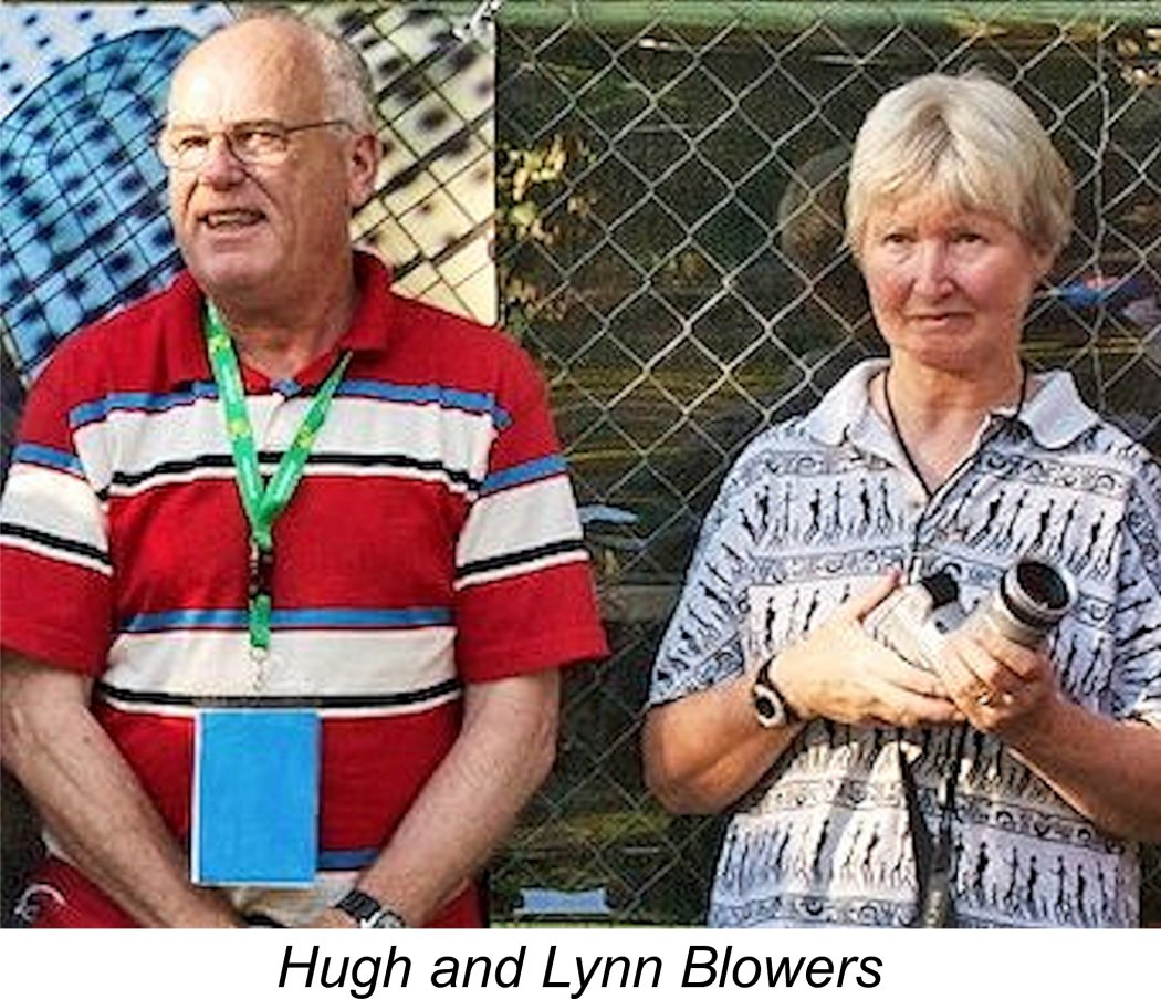 Any article on a subject of this nature is entirely dependent on the quality of the information that is made available by others. Lynn was most punctilious in acknowledging the help that she received from a number of primary sources. In turn, I hereby acknowledge my own inherited indebtedness to all these individuals. In particular, most of the company details that were provided for the original article were by courtesy of the recognized authority on Rowell Motors, George Blair. All of us are greatly indebted to George for his efforts to preserve the history of this company.
 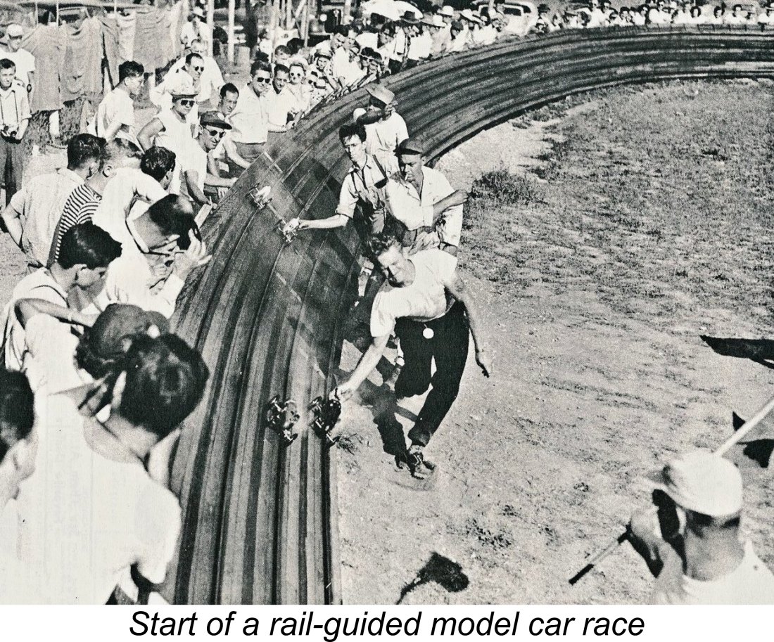 Prior to the refinement of dependable multi-channel radio control systems beginning in the early 1950's, the all-out use of large high-performance model engines was a practical proposition from a safety standpoint only in applications where the model remained under physical restraint at all times. In the absence of reliable radio gear, this meant models which followed a circular path at the end of a centrally-secured wire. This was referred to as tethered operation of the models in question.
 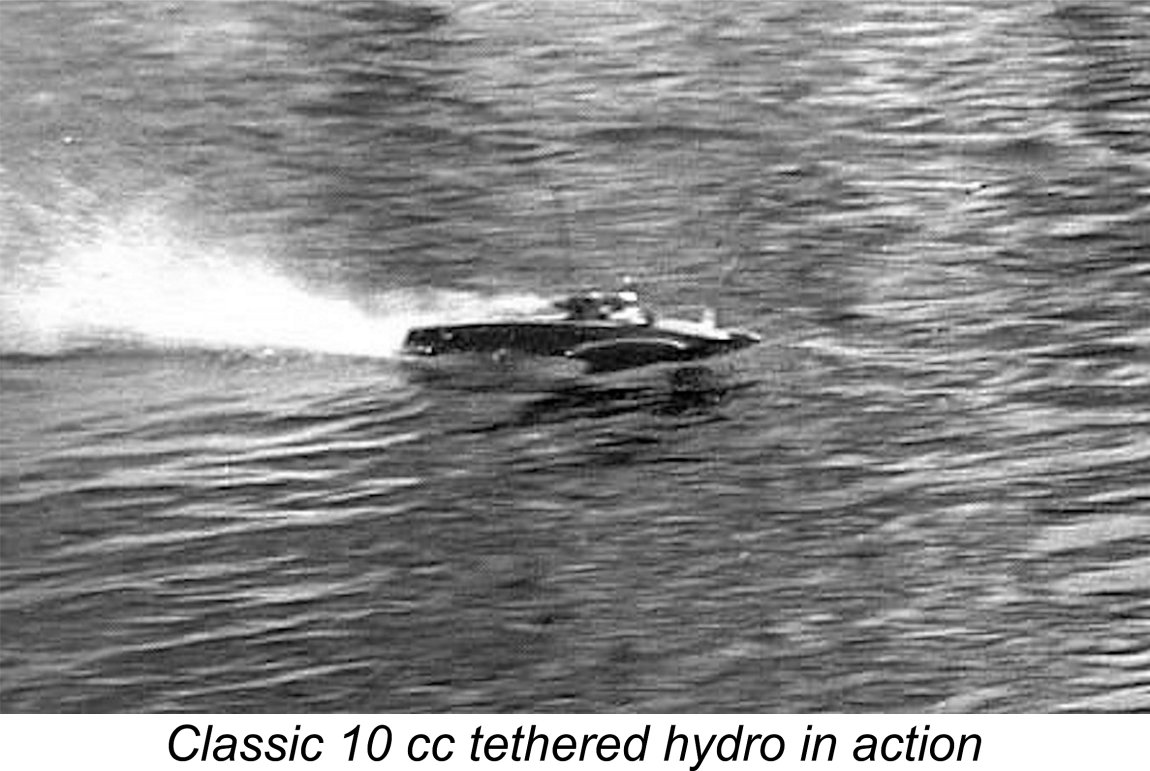 Although radio control has dominated the model aircraft scene since that time, control line flying continues to retain a dedicated group of adherents (including myself) who are drawn by the closeness of the pilot to the action as well as the sense of direct tactile feedback from the model that control line flying alone can impart.
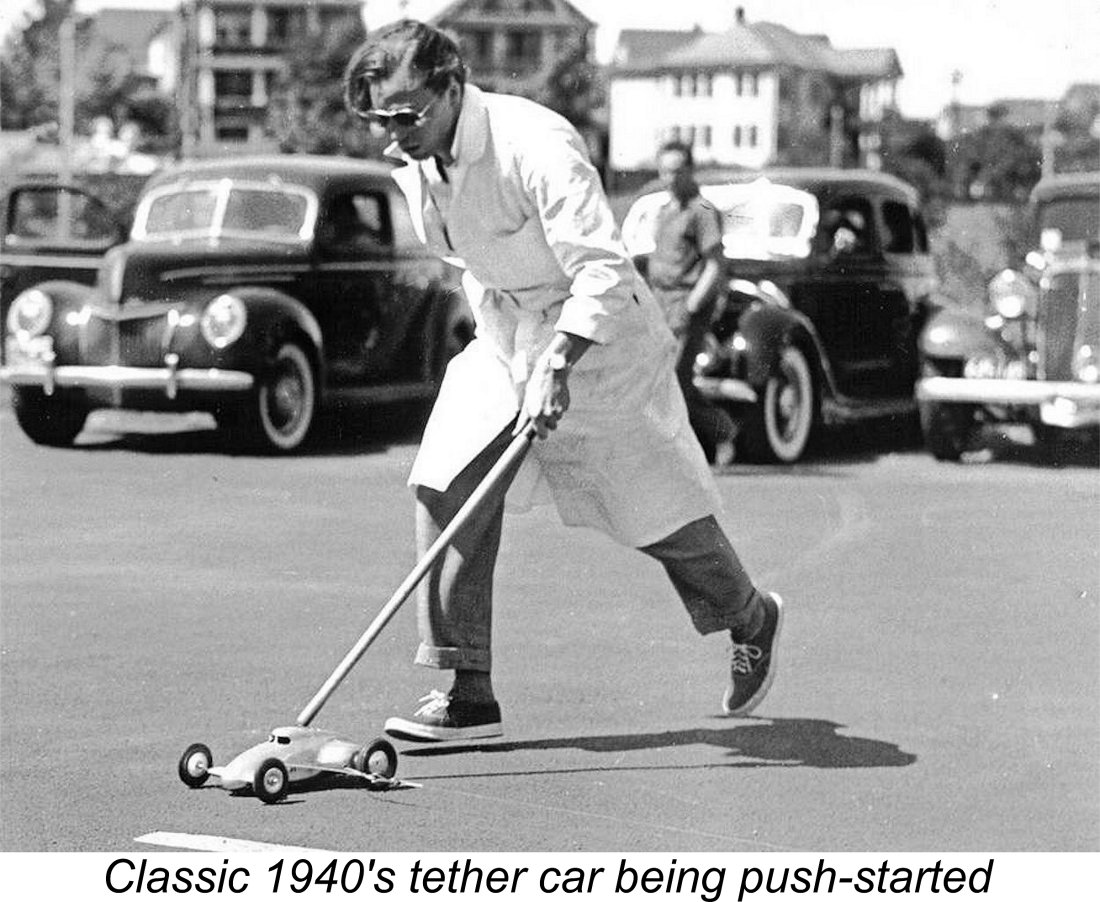 By contrast, the parallel sport of tethered car racing was a relatively late starter in Britain. Led by the famous
 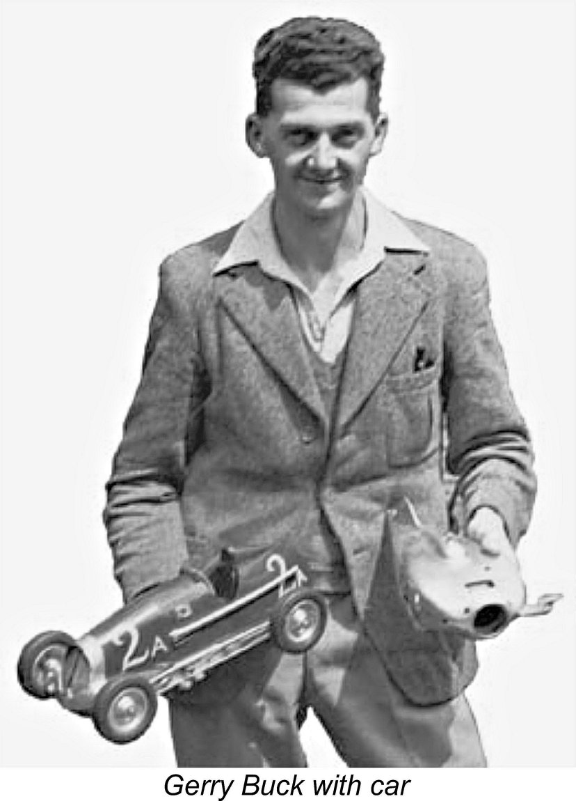 Somewhat illogically in view of the severe rationing of petrol (gasoline) which prevailed at the time, the operation of model I/C engines for purposes other than flying was not prohibited. “
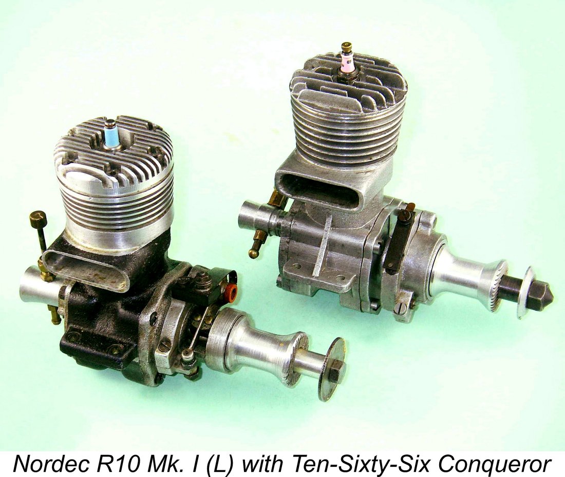
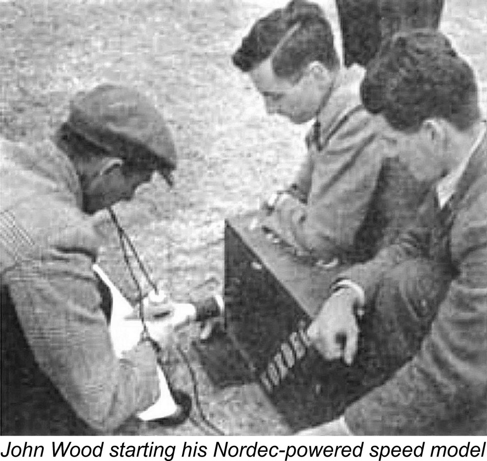 It's interesting to observe that all three of the above-mentioned designs appear to have been inspired by a genuine passion for the modelling hobby on the part of their instigators. The Ten-Sixty-Six and Rowell ventures were unquestionably both established as a result of their respective founders' well-documented interest in model car racing. The makers of the Nordec series were already well-established in the full-sized automotive business, thus having no economic incentive for entering the relatively limited field of big-bore model racing engine manufacture. Their entry into this field was due entirely to the fact that their works manager and chief designer John Wood was a keen participant in control line speed model competition. It was undoubtedly due to Wood's enthusiasm that the company ownership was persuaded to become involved in this field.
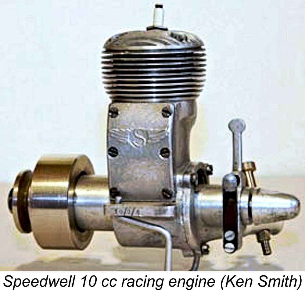
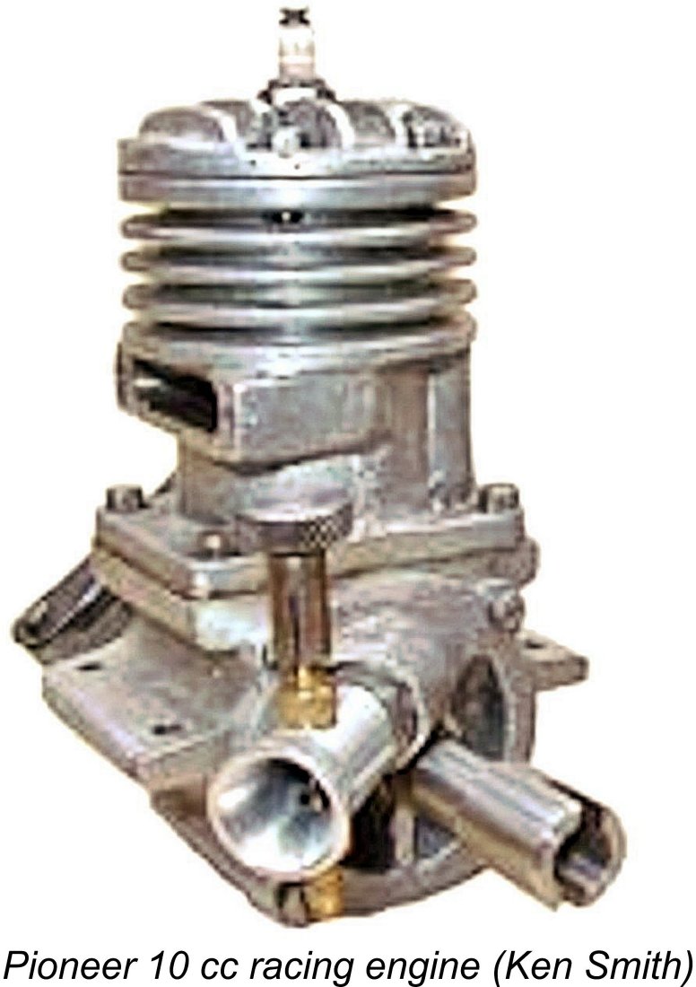
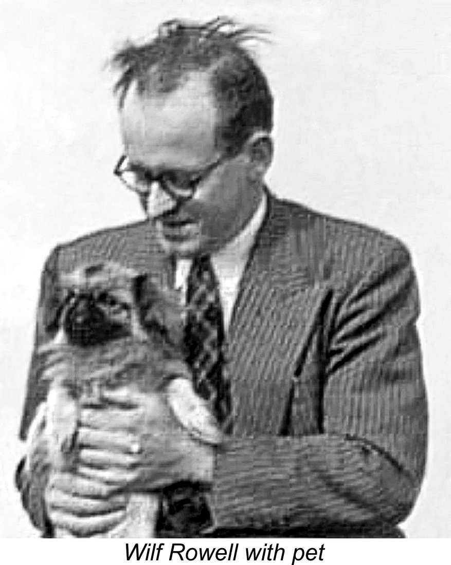 Wilfred George Rowell, always known as Wilf, was a professional engineer whose main field was the design of industrial cranes. Contrary to a widespread belief, he was not a native Scotsman, having been born in 1915 at Wall in Northumberland, England, a little to the south of the border with Scotland. He served his apprenticeship with Hexham iron founders Tyne Metal Co. Ltd., subsequently working for various industrial crane makers including Cowan Sheldon of Carlisle, Herbert Morris and finally Coles Cranes. By 1947, at the age of 32, he was living and working in Dundee, Scotland. He was to spend the rest of his life in Scotland.
 In July 1947, a letter appeared in “Model Car News” announcing the formation of the Dundee and District Model Racing Car Club, the secretary being one W. G. Rowell. When this article was originally published, I had identified a paved circle located on Balgillo Road East on the outskirts of North Dundee as being a likely remnant of the club's track. However, field work on the ground by my colleague Rob Nellies has confirmed that this is, and always has been, part of a children's play area.
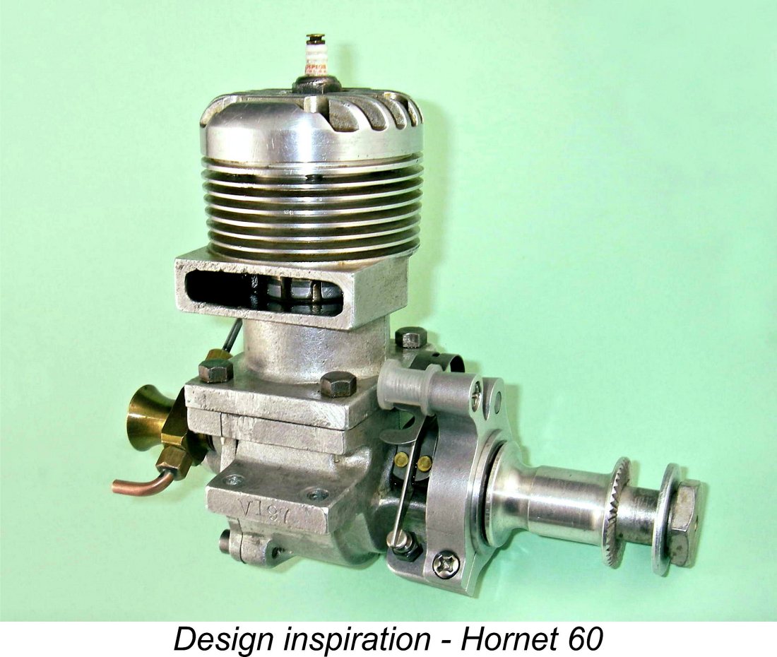
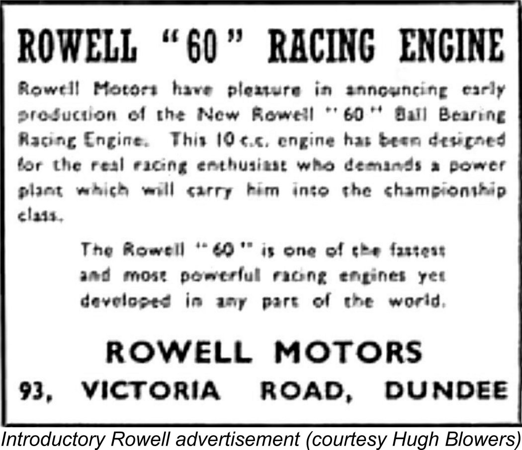 In the summer of 1948, advertisements began to appear for the Rowell 60 racing engine, then in its Mk. I configuration as illustrated below. This initial version of the engine clearly drew a healthy share of its design influence from the American
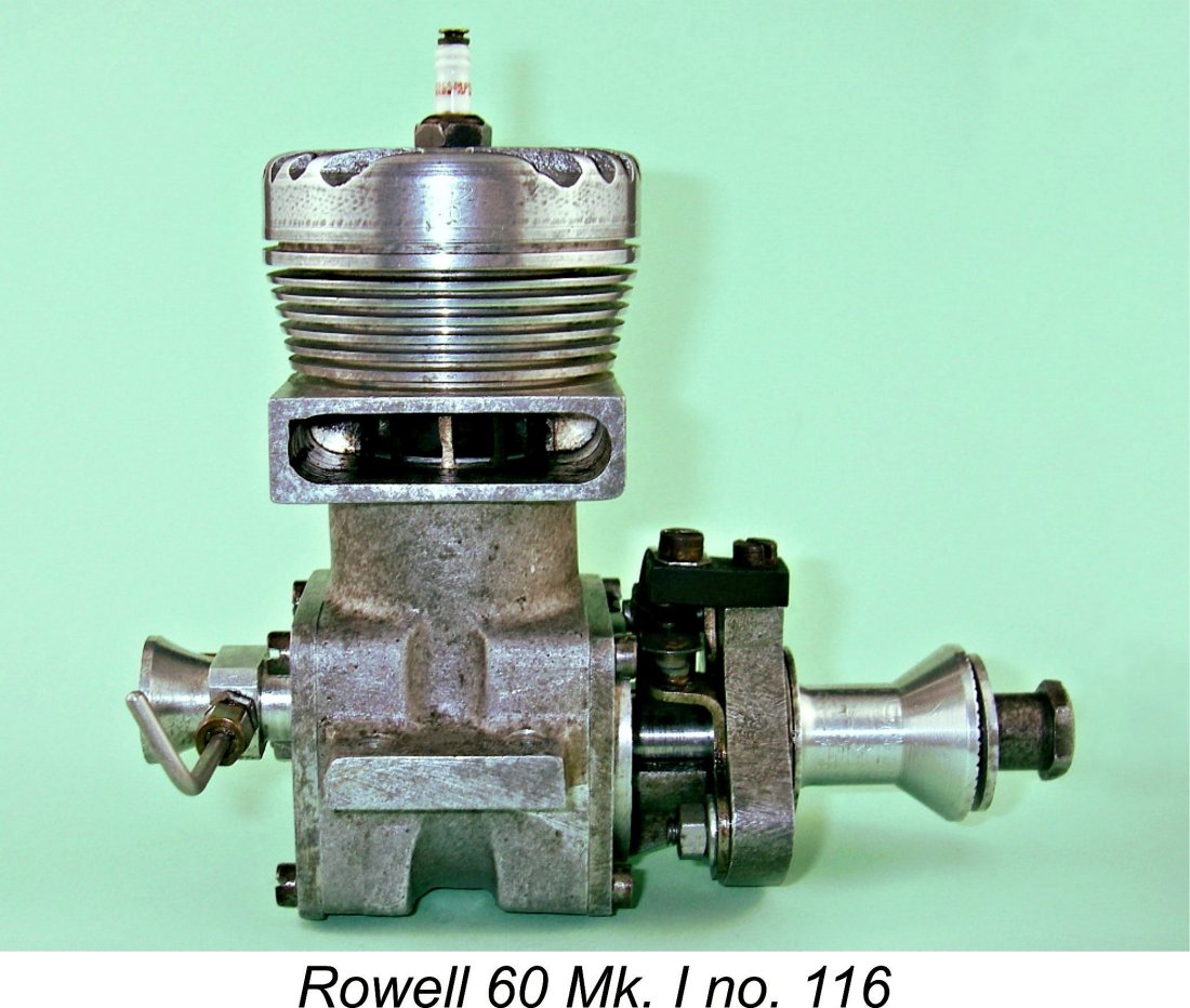
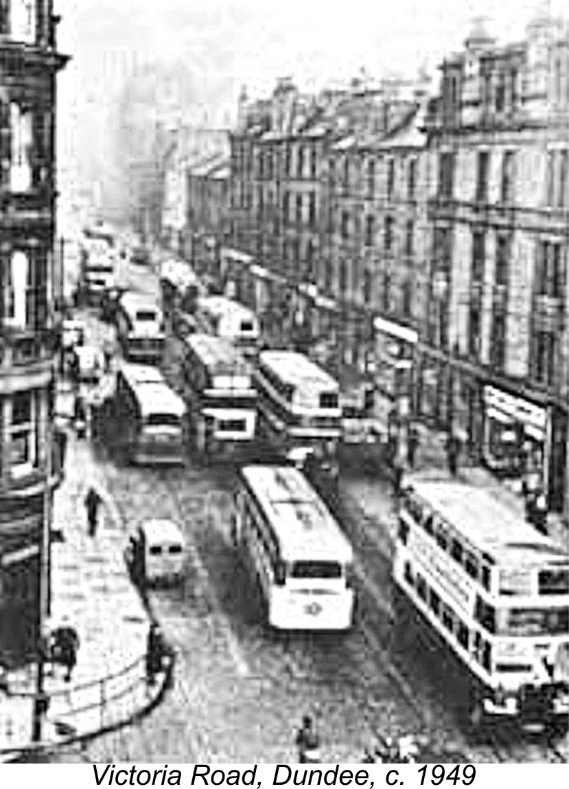
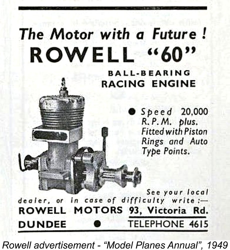 Although undeniably high, these prices were directly comparable with those charged for one of the Rowell's chief British competitors, the Nordec R10. By contrast, the basic price of the competing Ten-Sixty-Six Conqueror in factory-finished guise was a “mere” £8 5s 0d (£8.25) for the spark ignition version and £8 2s 6d (£8.13) for the glow-plug model. However, most of the Conquerors were sold in kit form to model engineers. In that form, they were very much cheaper than either of their rivals at a very economical £2 17s 6d (£2.88), but required a great deal of highly skilled work to complete. In general, the Conqueror appealed to a somewhat different market sector. Like the Nordec, it also came nowhere near matching the performance of the Rowell.
 still proudly proclaimed that it led into the "OFFICE"! The main factory was taken up by the roofless area to the right of the office block, but only one wall still stands.
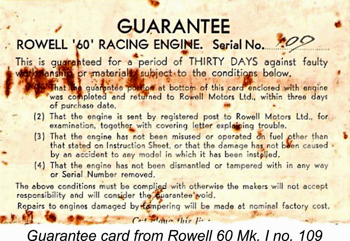
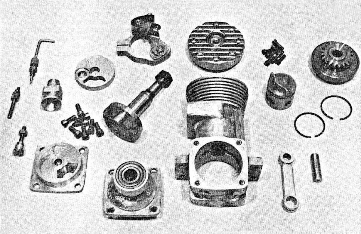 The Rowell 60 was a more or less conventional big-bore racing engine of its day, displaying a mixture of Hornet and McCoy influences. It featured the standard combination of rear disc valve induction, big-bore venturi with surface jet needle valve, bolt-on front and rear housings, twin ball-race crankshaft, automotive-style timer, high-crowned aluminium baffle piston with two rings and cross-flow loop scavenging. The accompanying component view which appeared in the May 1950 issue of "Model Engineer" may help to clarify the following detailed description.
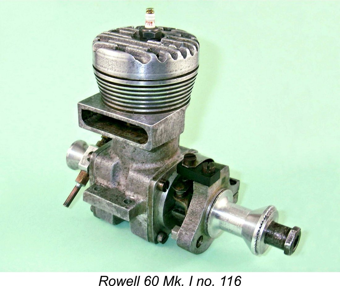
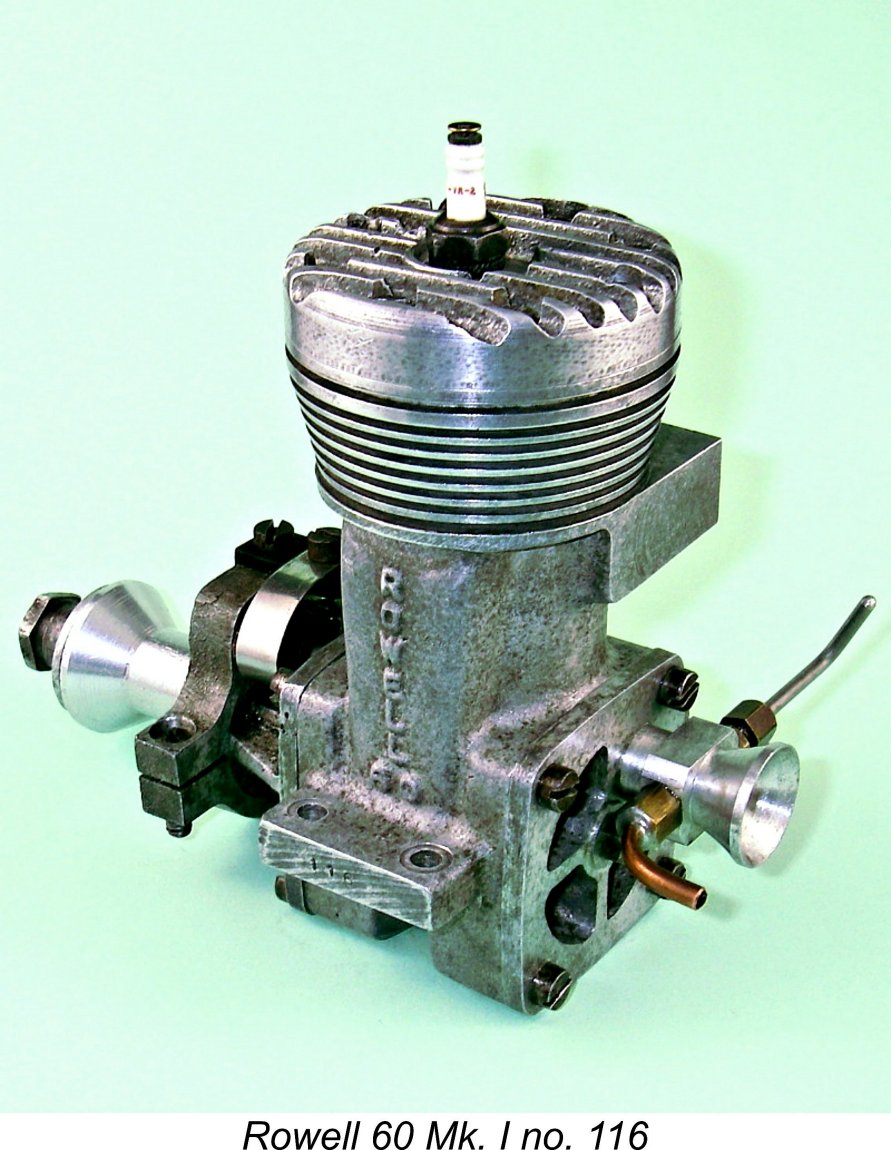 actually acted as helper on this model on a few occasions, thus getting a close-up (and extremely noisy!) view of a Rowell 60 in action. My recollection is that the engine started and ran well and got the model into the air with no problems but was not competitive against the contemporary opposition. Sounded impressive, though!
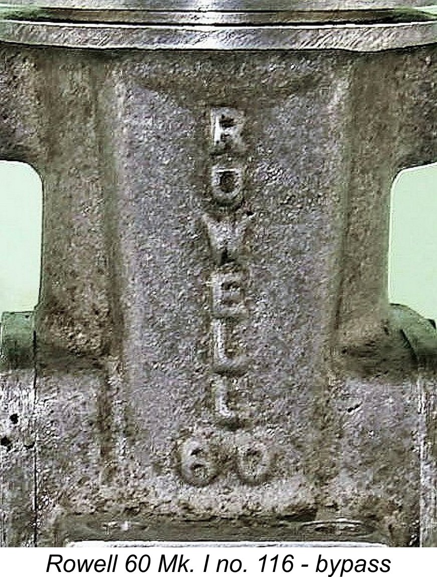 with particular attention being paid to the achievement of outstanding working fits and finishes. In the view of many observers, the standard of construction exceeded that applied to the famous McCoy engines from America. Based upon an examination of my own examples, I wouldn’t argue with that opinion.
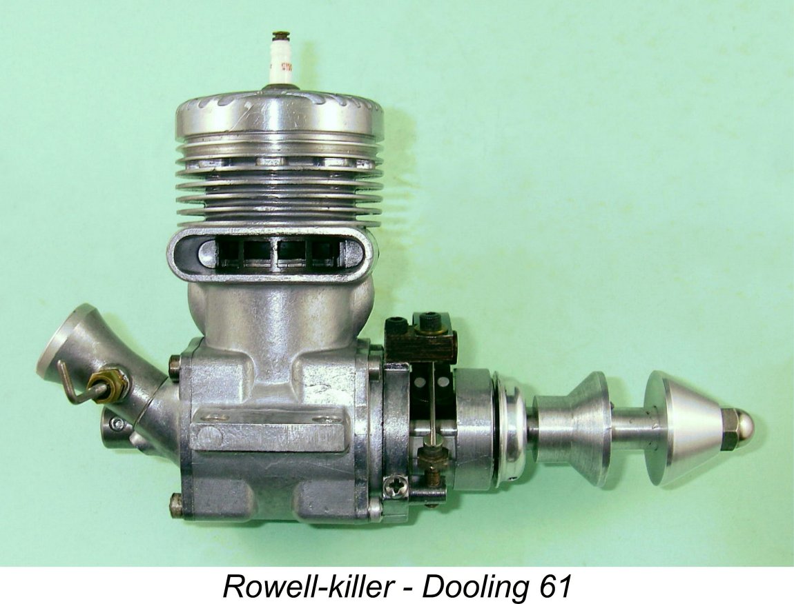
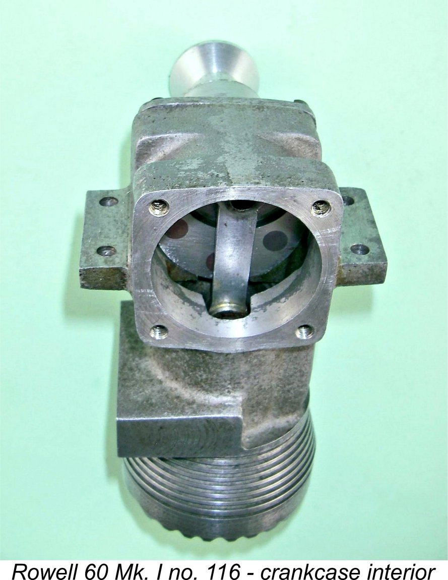
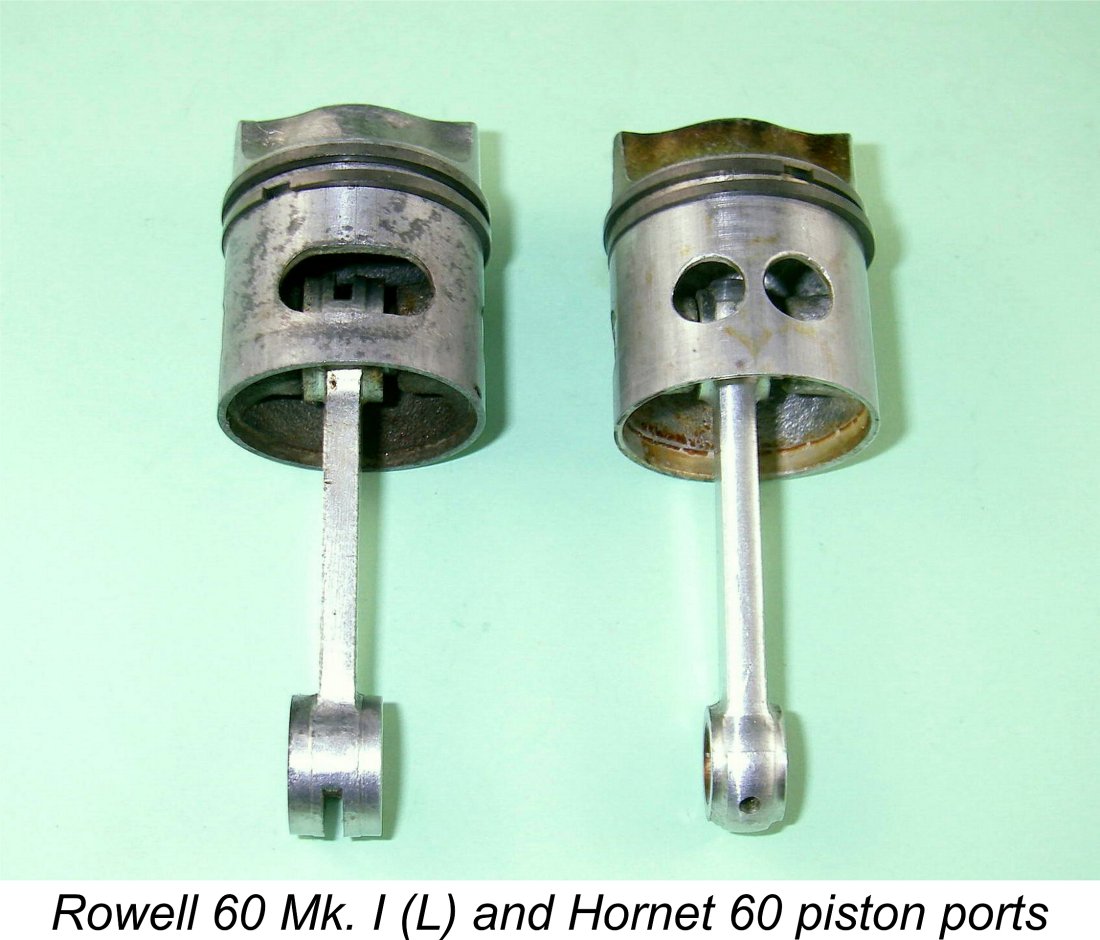 The piston porting used in the Rowell 60 appears to have taken two distinct forms. Many examples used matching pairs of drilled circular ports exactly like those used in the Hornet 60 as illustrated at the left. However, my own illustrated example has a single port of oval "race-track" form in the piston skirt to go along with a matching oval opening in the cylinder wall. The effect of this is of course to further open up communication between the piston interior and the bypass passage - a good feature from the standpoint of the engine's breathing capacity.
 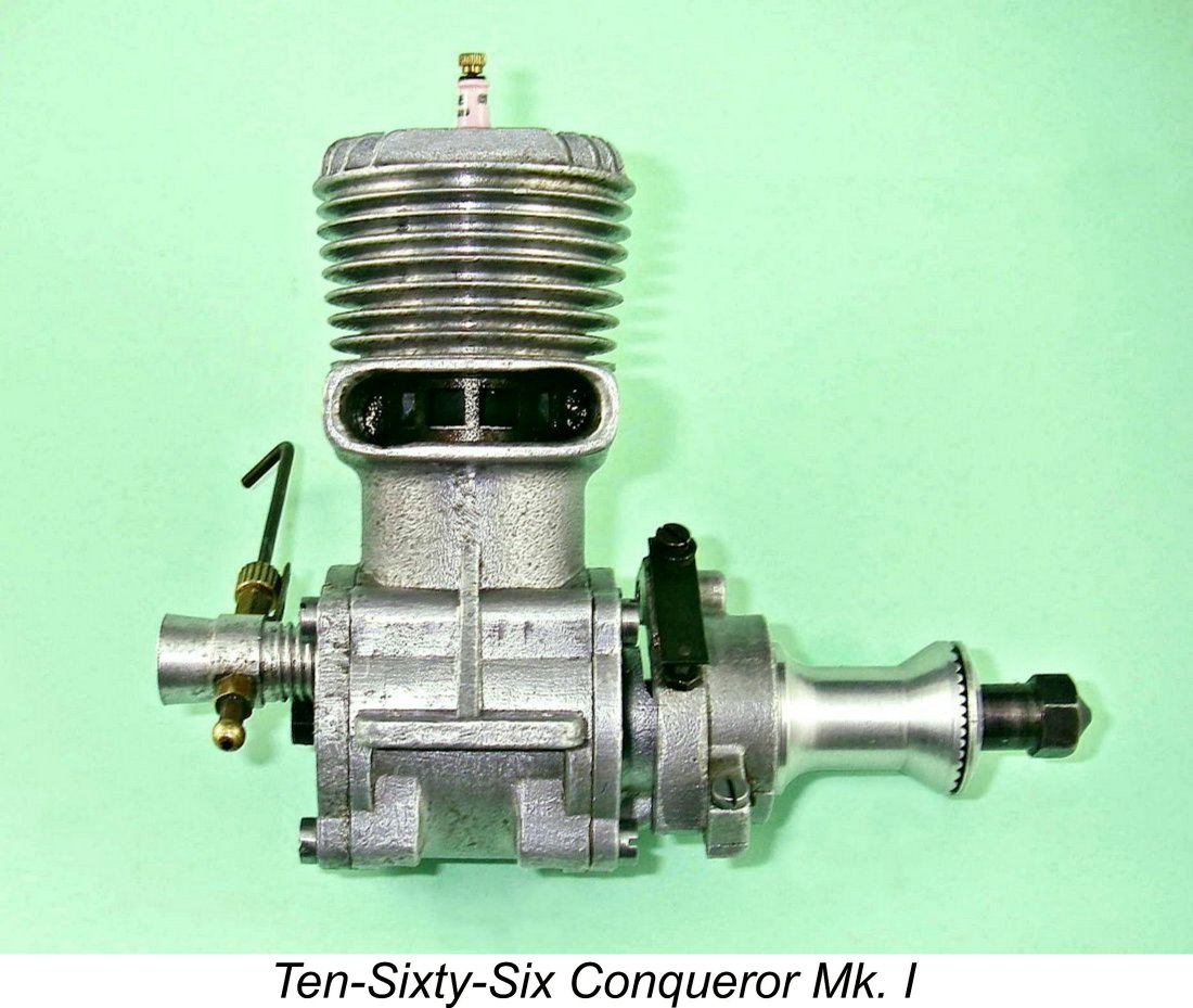 Like the competing Ten-Sixty-Six Conqueror, the port timing of the Rowell 60 was very much on the conservative side. The figures measured by Dick Roberts in the course of his 2008 test of a Mk. I Rowell 60 (see below) were approximately 130 degrees for the exhaust and 110 degrees for the transfer, very close indeed to figures taken from my own Conqueror.
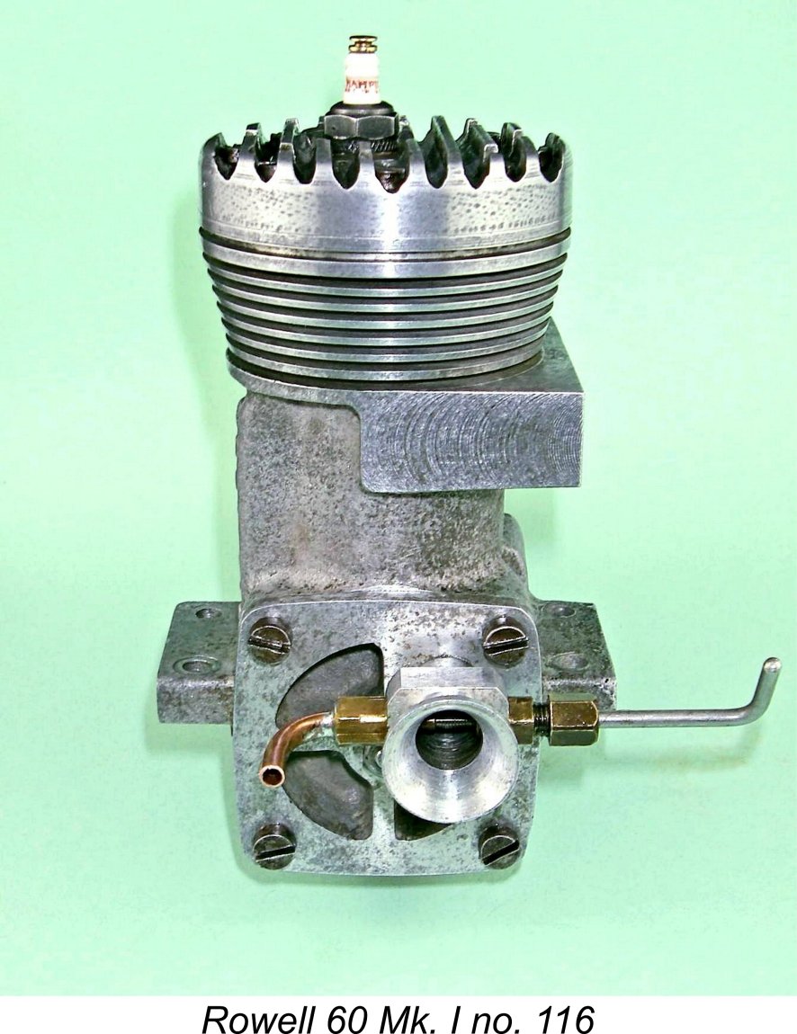 The 0.350 in. (8.89 mm) inside diameter of the screw-in intake venturi was well chosen, since in combination with the use of a surface jet needle valve of conventional racing engine design it provided sufficient suction to permit the operation of the engine without pressure feed while still ensuring an adequate supply of fuel mixture. To further assist suction, the jet was actually extended some distance into the venturi throat, thus placing the point of discharge well into the fast-moving induction air stream. The venturi bore was substantially larger than the standard venturis used on both the Rowell Mk. I’s Conqueror and Nordec rivals. Examples have actually been reported with 0.375 in. dia. (9.52 mm) venturis - these may either be owner modifications or represent a change made by the manufacturers at some point.
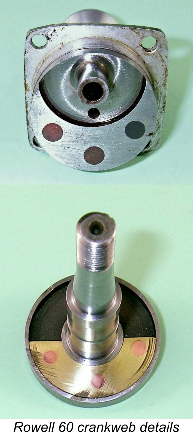 The connecting rod was machined from light alloy. Somewhat unusually, this component was un-bushed at either end. The crankshaft had a fully circular web with a heavy counterbalance machined onto its rear (crankpin) face. The design of this component clearly reflected that of the Hornet in that the forward face of the crank disc was recessed, with additional counterbalance being provided through the inclusion of a crescent-shaped metal weight set into the recess on the counterweight side. Unlike the Hornet, which used a steel counterweight which was welded in place, that used in the Rowell was of brass and was secured using three rivets which passed through the crankweb.
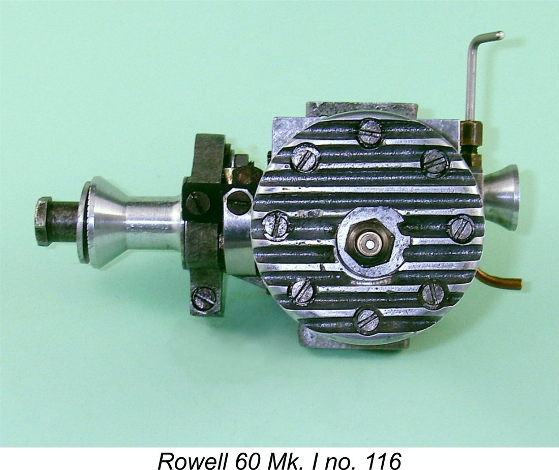
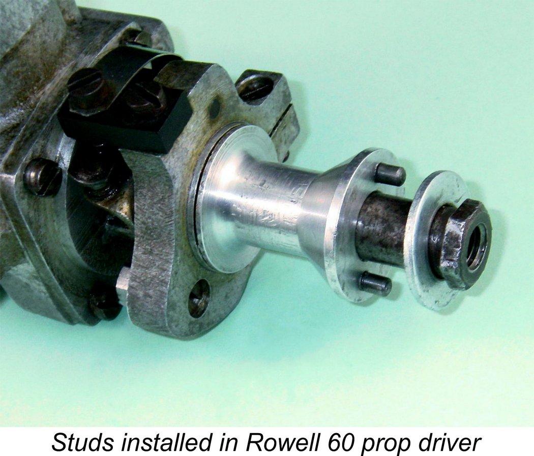 plug version of the engine with a head having a somewhat lower compression ratio than that of the sparker. It’s possible that the glow-plug versions were in fact so equipped. However, the absence of surviving examples denies us any opportunity to confirm or refute this point.
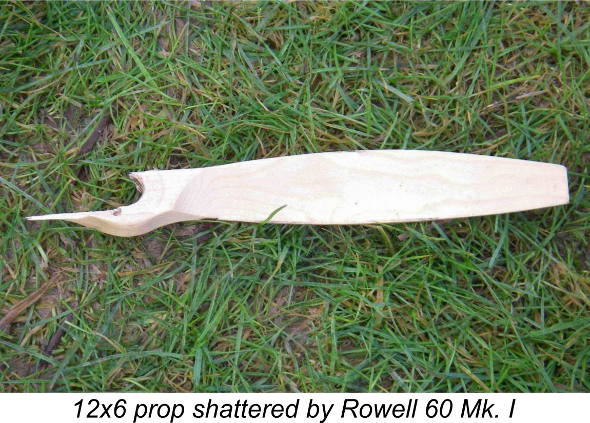 face as well as a lower compression ratio and significantly lower torque output. However, even this proved inadequate upon initial testing - the studs are of course very effective in transferring torque loadings between the driver and the prop hub but do nothing to support the prop hub as it resists the combination of centrifugal forces and cyclic torsional stresses imposed upon it by the prop blades. I shattered two wooden props during starting attempts before deciding that in the interests of self-preservation, further measures were required! Accordingly, I ended up knurling the driving face of the driver. This proved completely effective.
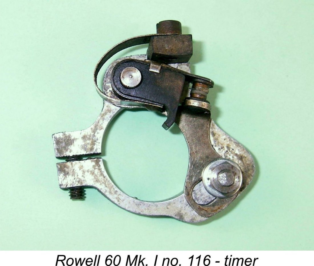 The timer was of some interest, incorporating an effective adjustment feature for the point gap. The fixed point was mounted on a stamped metal bracket that rotated about the moving point pivot. It was restrained from rotating by a bolt which passed through both the timer frame and a slotted hole in the bracket, being secured to the frame by a nut. Clearance was adjusted by first slackening off the clamp nut and then rotating the fixed point assembly slightly. The clamp nut was then re-tightened.
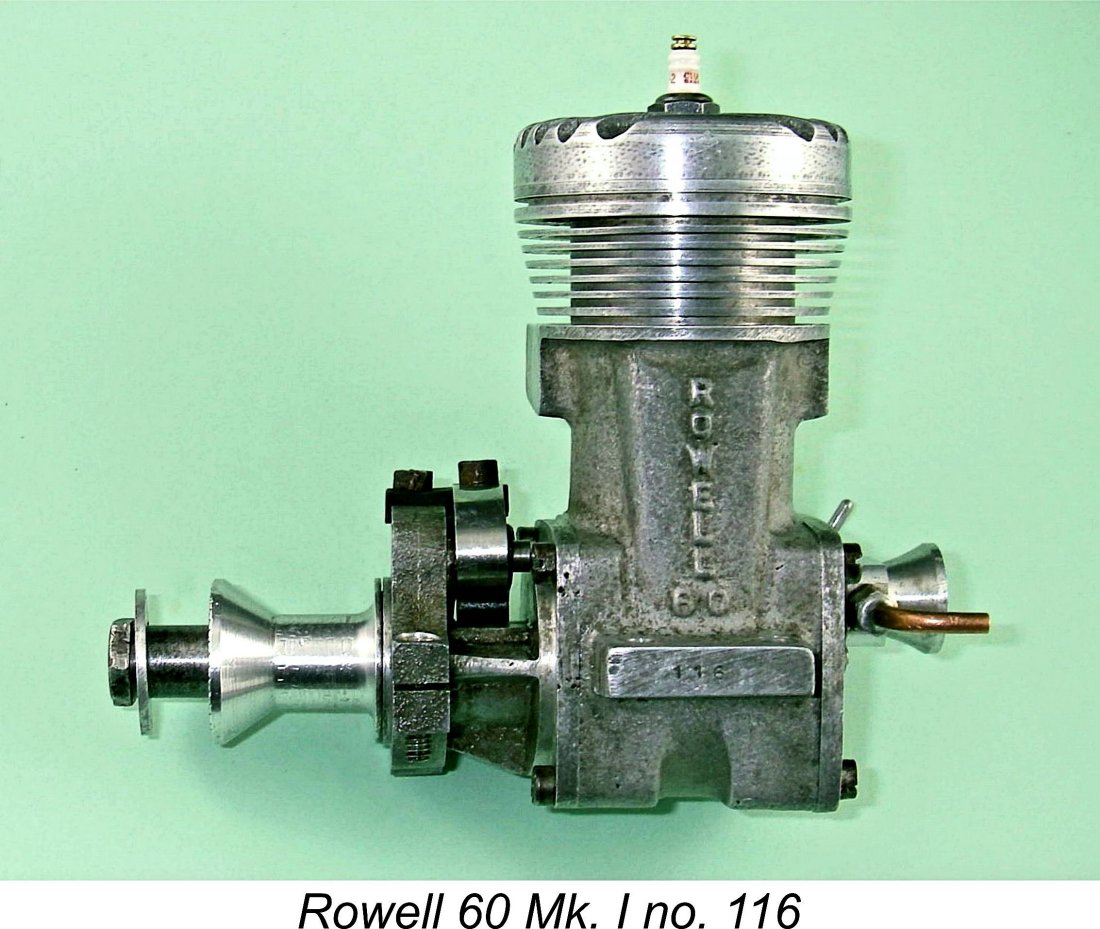 As the most powerful model engine yet to emerge from a British manufacturer, the Rowell 60 naturally attracted the interest of the engine testing gurus of the day. Prominent among these was the redoubtable
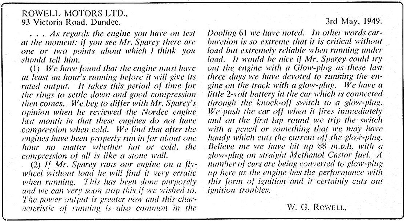
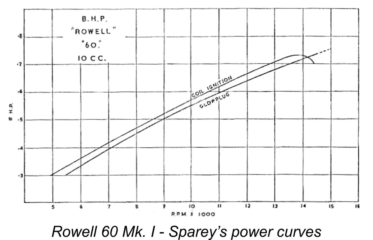 Why Sparey would expect an engine which was clearly designed and timed for high speeds (by the standards of the day) to operate happily at such pedestrian speeds is quite beyond rational explanation - why even test it at such speeds?!? However, he repeated this error in test after test, never seeming to grasp the futility of testing glow-plug engines at speeds far below those at which they were designed to operate. The "misfiring" to which he referred was most likely detonation!
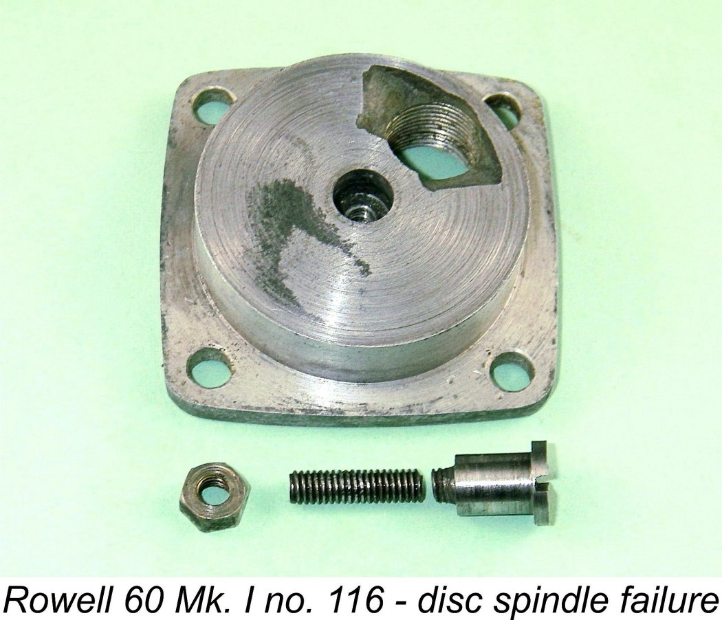 engine. Little damage was sustained apart from some scuffing of the con-rod, but this put an end to the test. The engine had however matched the output achieved on spark ignition, albeit at a somewhat higher speed, with evidently more still to come.
 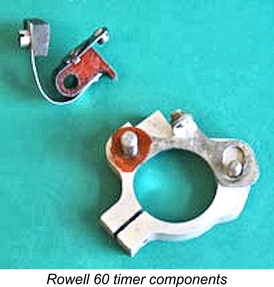 Tester Dick Roberts described the engine in some detail and put it though its paces on the bench. He reported some difficulty in achieving the specified .006 in. point clearance using the adjustment system described earlier. The rotation of the fixed point bracket by only a microscopic amount makes quite a difference to the gap, rendering the establishment of precisely the right gap somewhat finicky. The setting also tends to shift while tightening the clamp nut. Dick tried inserting a feeler gauge and then making the adjustment, but this did not work as the moving point spring was not strong enough! I have actually found my example to be easy enough to adjust, but I must admit that the very clever and effective point adjustment arrangement seen on the rival
 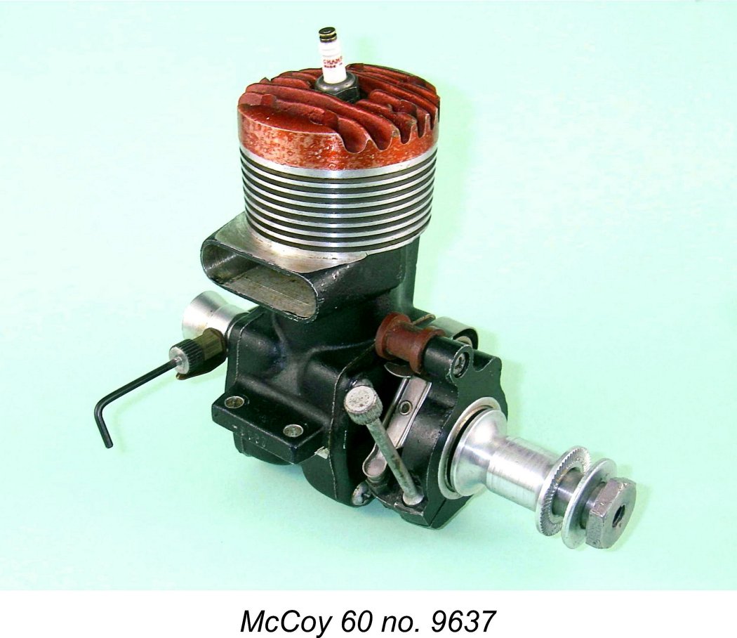 speed is marginally less than that at the lower figure, it would appear that the engine tested by Dick peaked at a speed lying somewhere between these two figures, probably producing around 1 BHP at some 11,500 rpm. This in turn implies the development of considerably greater torque than that found by Sparey.
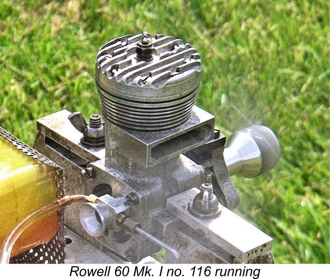 I can confirm Dick's statement that the Rowell is very easy to start by hand despite the rather daunting compression ratio, also running very smoothly. For hand-starting on glow-plug ignition, I find that my usual big-engine "reverse-bounce" technique is by far the safest - set the prop at "ten past eight" viewed from the front with the piston at bottom dead centre, administer a healthy prime and then HIT the prop backwards from the bottom dead centre position with the plug activated. The inevitable backfire almost always starts the engine in the correct direction. Using this method, the Rowell is a one-hit starter practically every time. The compression seal provided by the rings is outstanding - a genuine "stone wall" just as Wilf Rowell claimed.
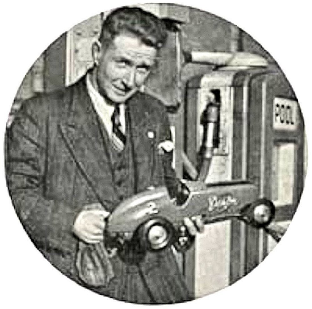
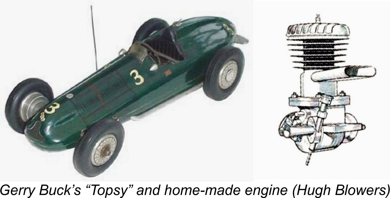
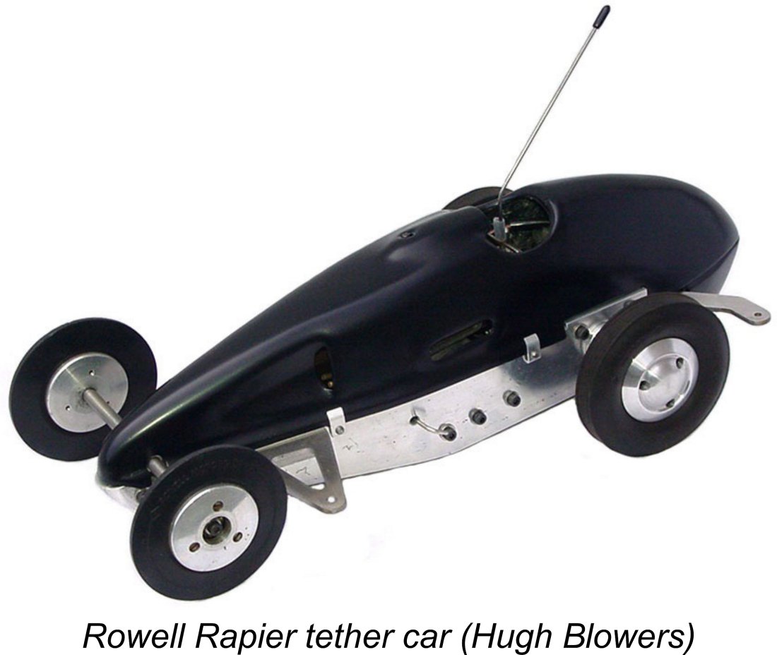 Having said this, they did include a plan for the Rowell Rapier, which was quite unlike any other car being produced anywhere at the time - definitely a Rowell original! The Rapier deviated from common practice in almost every aspect. Instead of a conventional chassis or pan, it had solid aluminium plate side members that tapered sharply towards the nose, being joined at that point by an aluminium casting that carried the front axle mounting. Further bracing was supplied by the engine, crank support, gearbox and tank, all of which were bolted between the side plates and thus functioned as part of the structure. The body was a complex two-piece aluminium stamping. The design was expressly intended to be suitable for home construction.
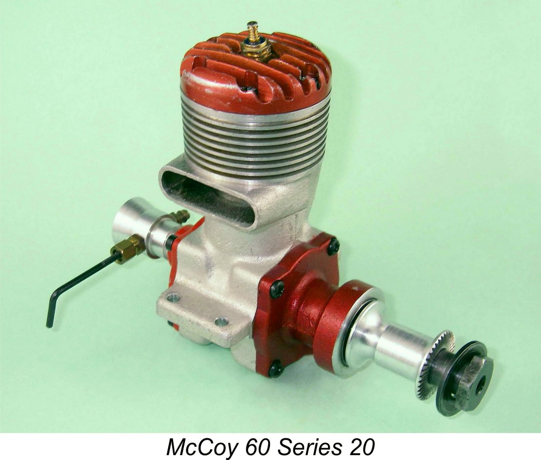 From the above comments, it may be seen that the Rowell 60 stood up well to a close examination in isolation. However, the Rowell was not competing against itself but rather against other engine designs. In R. H. Warring's 1949 book "Speed Control Line Models", the author compared the Rowell with the American Hornet, McCoy and Dooling 10 cc models as well as the British Nordec. In the glare of this comparison, the Rowell did not fare so well.
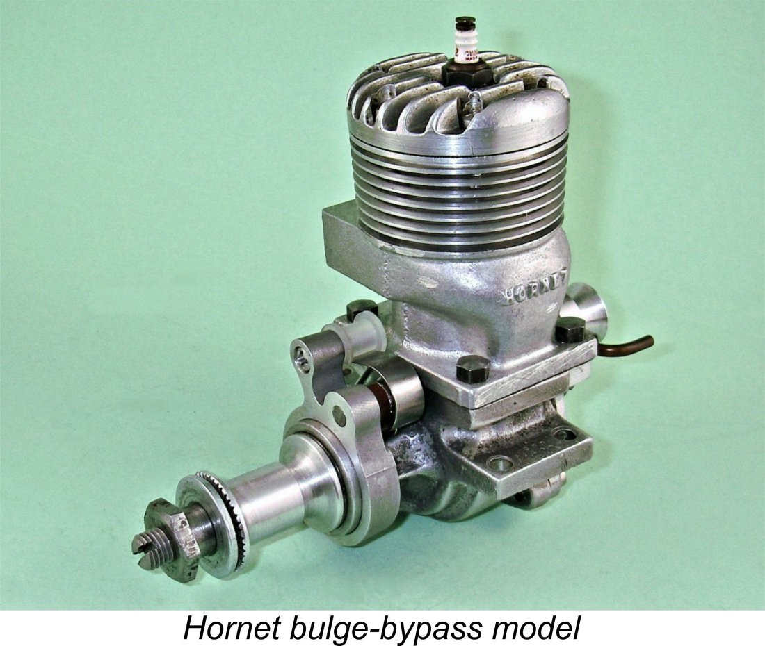
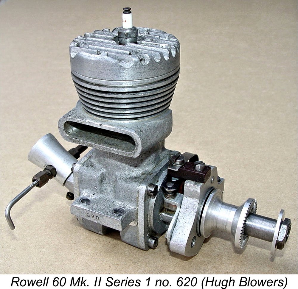 The promised revised model duly appeared on schedule. It featured a lighter crankcase having an enlarged bypass passage which was both wider and deeper in section. The revised case also sported a rounded exhaust stack as opposed to the square section stack featured on the Mk. I.
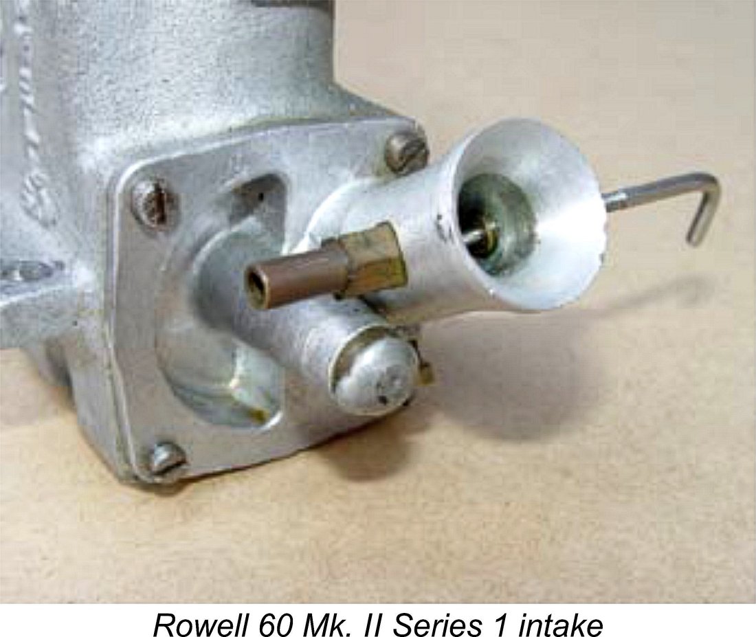
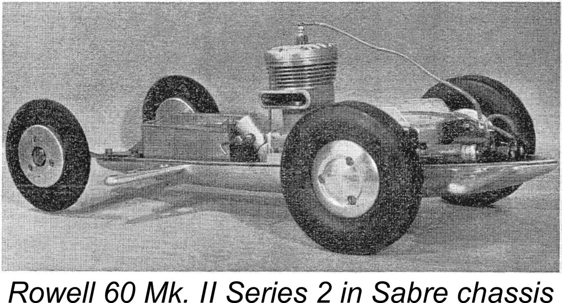
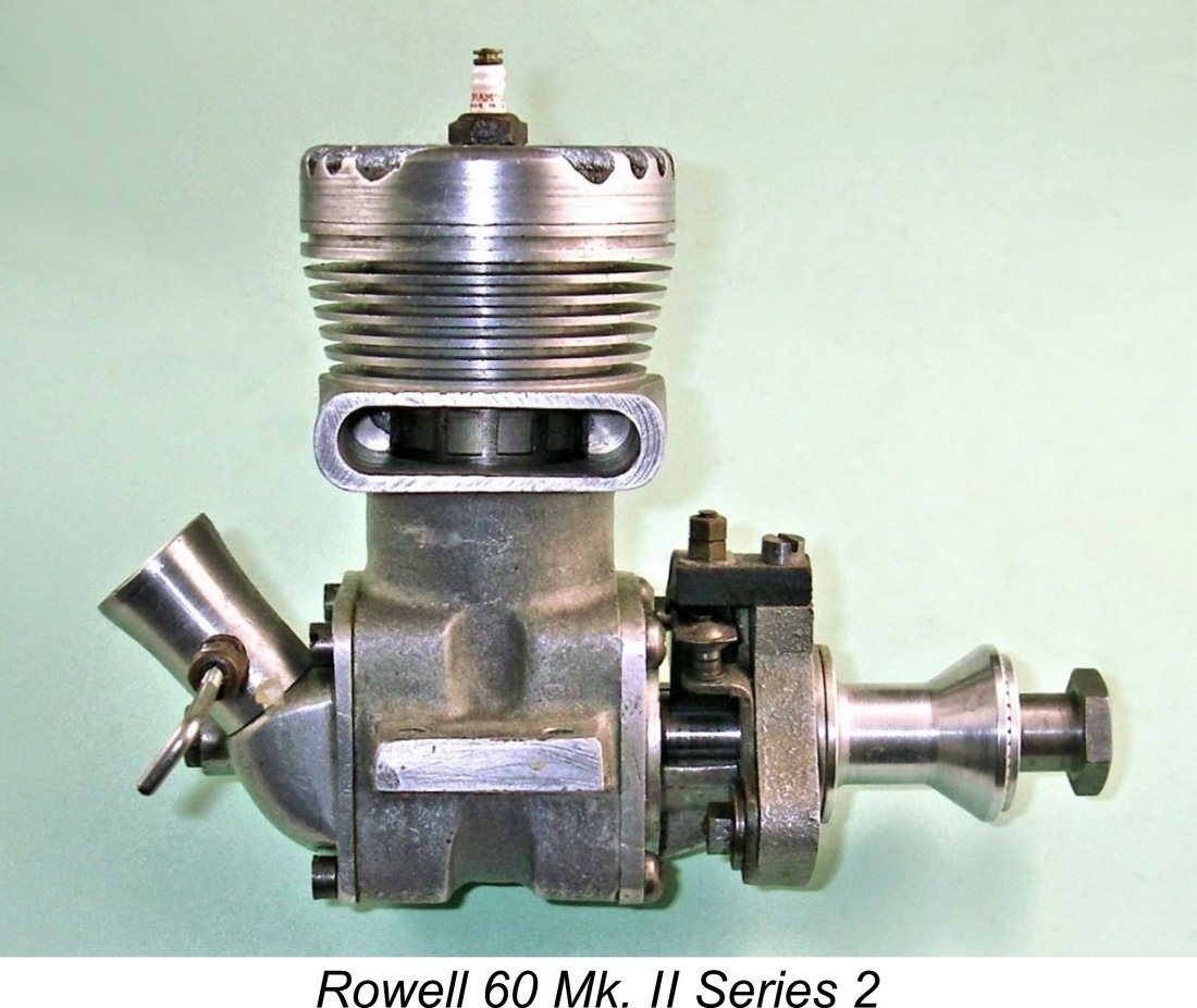 The Rowell 60 Mk. II Series 2 illustrated here is a little-used and unmodified example which was missing its timer as received. The engine had clearly spent most or all of its seemingly short running life in glow-plug mode - while the combustion chamber and piston crown bore clear evidence of at least some running, the cam area of the crankshaft bore no indication of the residual effects of cam follower rubbing, nor did the exterior of the front bearing housing show any of the usual scuff marks resulting from timer adjustment.
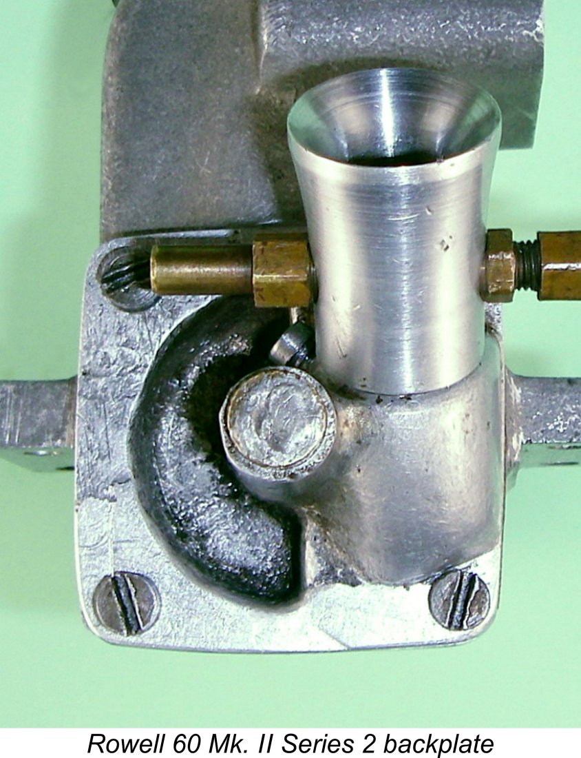 very competently restored by welding, but the owner had never got around to cleaning up the repair. I completed this work successfully, to the point that the repair is now quite unobtrusive - you probably wouldn’t notice it unless I pointed it out.
 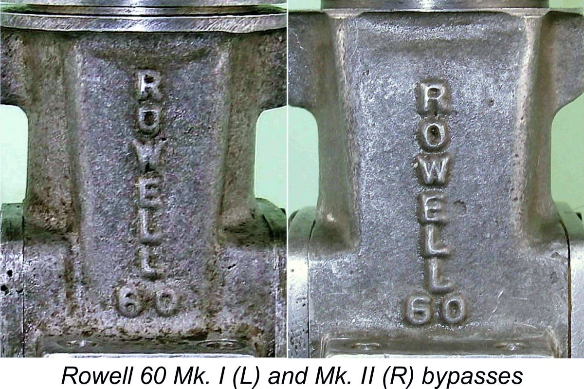 Turning now to the engine's design features, the only externally-visible differences that distinguish the Series 2 from the original Mk. II design (now referred to as the Mk. II Series 1 are the even more steeply-angled venturi seen in the accompanying image and the sand-cast backplate. The new sand-cast back-plate featured a curved intake stub. The main crankcase casting with its enlarged bypass passage (by comparison with that used in the Mk. I) appears to be identical to that seen in the Mk. II Series 1.
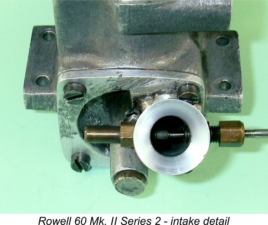 It might be asked at this point why the change was made to the more steeply angled intake venturi. Could this be a simple matter of slavishly copying the design of the all-conquering Dooling 61 which was then sweeping all before it? Well, Dooling influence may have played its part, but the fact is that the revised design permitted several distinct improvements to be made to the induction system.
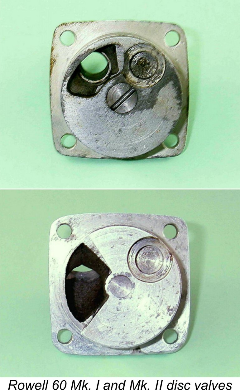 disc valve bearing despite the fact that in plan view it encroached considerably into the space occupied by that bearing. The accompanying illustrations should make this clear.
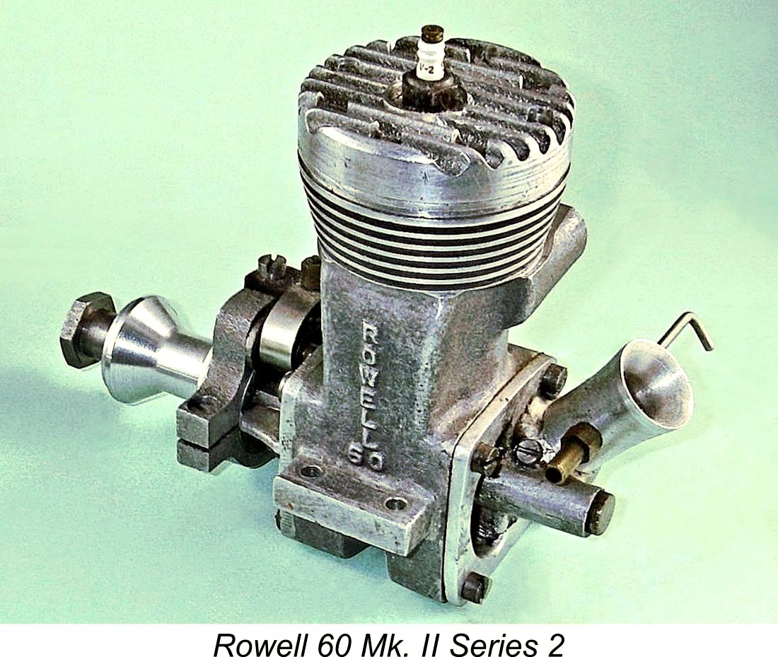 In fact, given the engine's greatly improved induction capacity thanks to its far larger venturi and backplate induction port, I would objectively question the need to delay the closure of the system to this extent. I would have been tempted to close the intake perhaps 15 degrees earlier, thus gaining the benefit of increased crankcase pressure prior to the opening of the transfer ports. That said, there is no evidence whatsoever that this example has been modified in any way - all of the as-cast surfaces on both the rotary disc and the backplate remain undressed. Hence the timing appears to be as established during manufacture.
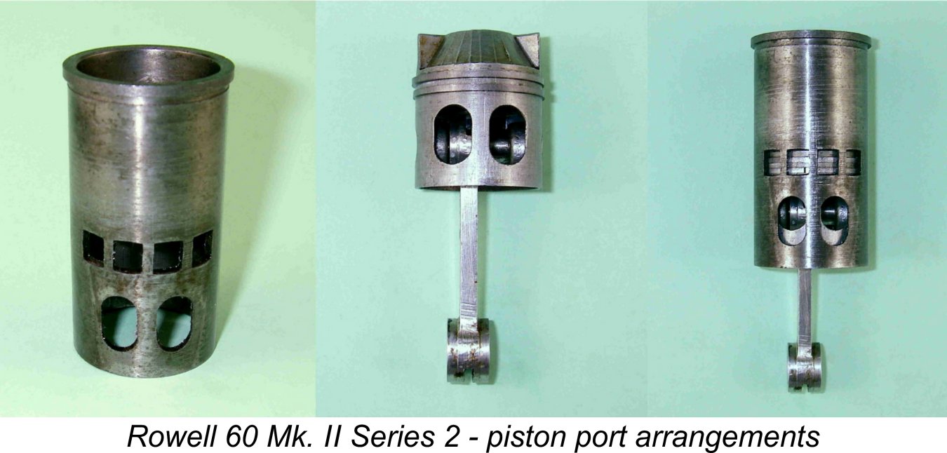 To address this issue, the revised design featured a pair of cylinder ports which were extended upward, maintaining an oval "race-track" form with no sharp edges to create stress concentrations. At the same time, the corresponding piston skirt ports were extended downward, again retaining a matching oval form. The result was that when the transfer ports began to open (as shown at the right in the accompanying illustration), the piston port system was already wide open and only got wider as the piston continued to descend. At all stages of the cycle, overall bypass entry area was substantially greater than the total available area of the transfer openings, thus presenting no undue constraint upon gas movement from the case to the cylinder. At first sight, a very rational and worthwhile improvement, which was actually a not-uncommon modification applied by knowledgeable users of the
 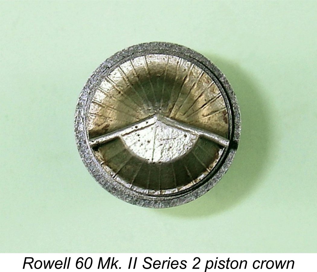 Moving on upwards, both the piston crown and the cylinder head were substantially changed. The crown of the die-cast piston now featured a baffle having a wedge configuration in plan view, with the interior of the wedge facing the transfer ports. The idea was clearly to promote a more focused movement of transfer gas towards the upper cylinder. Interestingly, the top surface of the piston crown was lightly ribbed, presumably to gain greater stiffness.
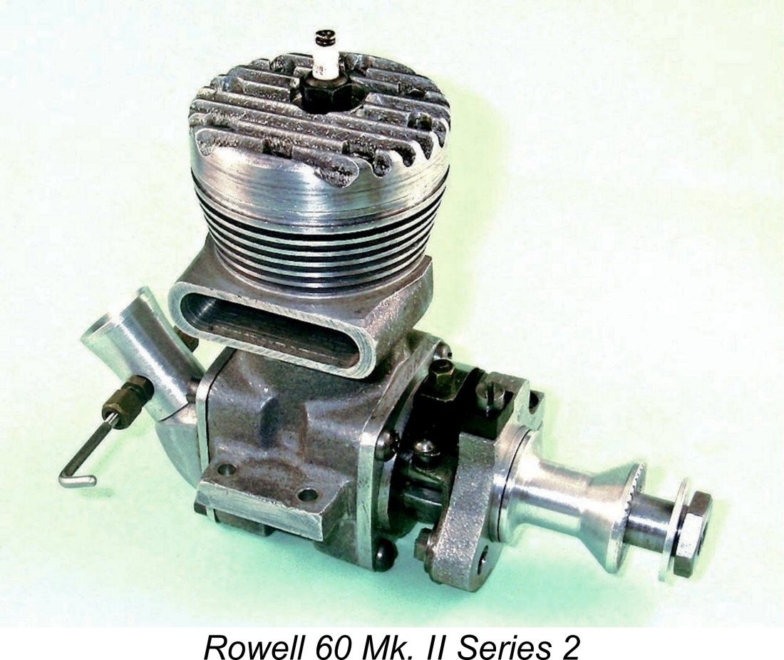
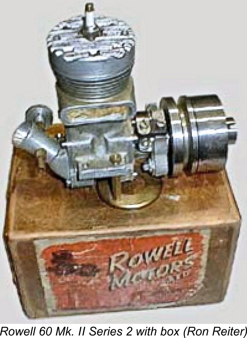 Since I don’t have access to a Mk. II Series 1 example, I'm unable to determine how many of these changes were carried over from the Mk. II Series 1 as opposed to being introduced in the Mk. II Series 2 model. I suspect that the four transfer openings were common to both the Series 1 and Series 2 variants, as was the revised means of mounting the rear disc valve.
 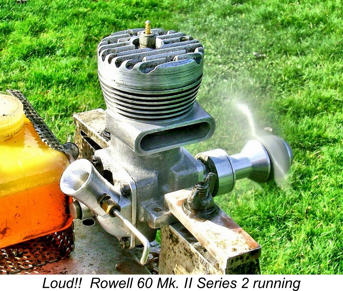 As it turned out, I needn't have worried! Contrary to my initial skepticism regarding its handling qualities, the Mk. II engine proved to be just as easy to start as its Mk. I sibling, merely needing a healthy prime followed by my usual reverse-bounce starting technique described earlier. Not only that, but it also confounded my expectations by turning out to be perfectly happy running on suction feed! I actually flooded it quite badly during my initial attempt using a gravity fuel system which was a challenge to manage.
 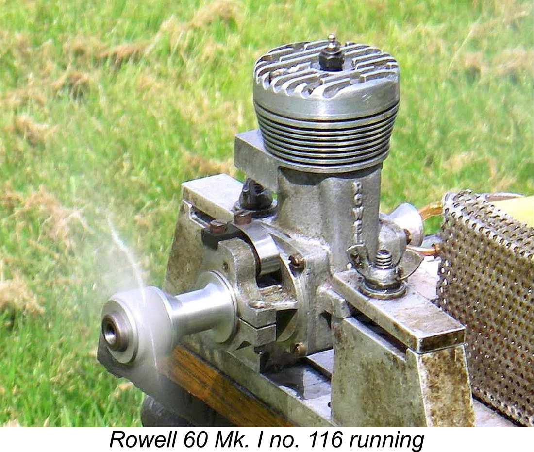 The fastest speed that I achieved was 16,100 rpm on the 10x4 APC, with the engine running as sweetly (and loudly!) as one could wish, with no trace of intake blowback. There's no doubt at all that the Rowell would run very well at even higher speeds than this, but I wasn't prepared to go any further with this very rare unit.
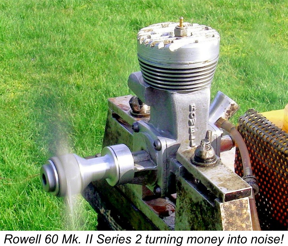 By contrast, the Mk. II Series 2 is just getting into its stride at the peaking speed of the Mk. I. In fact, power is still rising steadily as 15,000 RPM is approached. Although the estimate is based upon a rather small data sample, the above numbers clearly imply a peak output of around 1.23 BHP at somewhere in the neighborhood of 15,800 rpm.
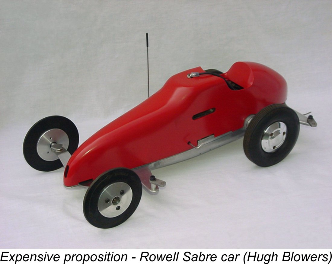 Despite the reduction in the price of the Rowell 60 to go along with its improved performance, it can't be denied that model car racing at this level was an extremely expensive business by 1950 standards. By the time a customer could bring a competitive 10 cc car to the starting line, his investment in that single model might well be on the wrong side of £40, a small fortune in those days, being equivalent to at least four thousand dollars in today's money, over 70 years on. In effect, the pursuit of model car racing at a competitive level in the 10 cc class was becoming an activity open only to those having the right combination of money and technical ability. Naturally, such individuals were very much in a minority.
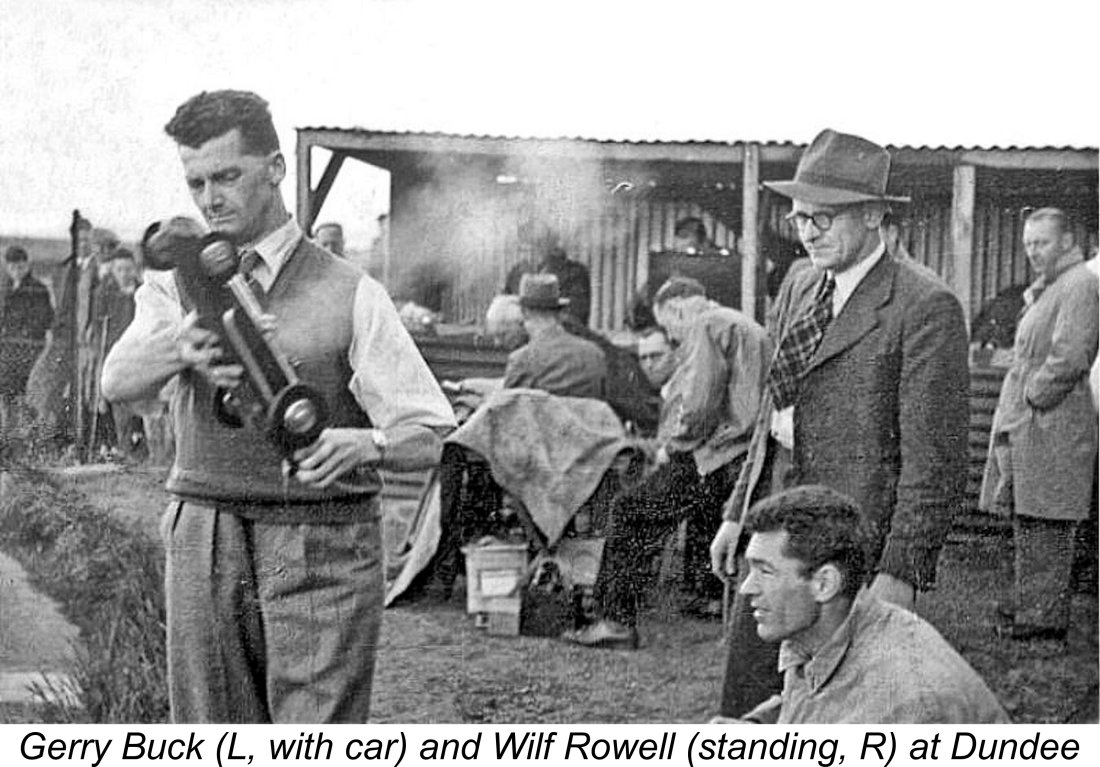 Despite this, a perusal of the race reports from 1950 shows that several prominent competitors adopted and raced Rowell Sabres, including Joe Riding and Gerry Buck. Gerry made the trip up to Dundee in August 1950 both to attend the Scottish Speed Championship meeting and to take delivery of his own Sabre fitted with the newly-introduced Mk. II Series 2 engine. Note the fact that no-one in the accompanying illustration is wearing ear protection while in the immediate vicinity of a running 10 cc racing engine! Hearing loss, anyone?!?
 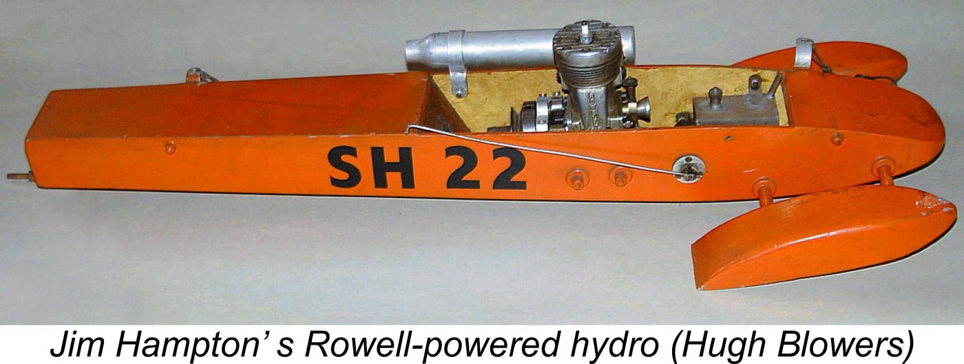 A similar situation existed in the tethered hydroplane world. Rowell supported the MPBA International Regatta in 1950, but the engines were not a great success in this discipline. Jim Hampton ran a hydro which was fitted with a Mk. 1 Rowell engine that Jim claimed to be very reliable and capable of consistently producing runs of around 40 mph. However, this was very far from competitive by 1950 standards.
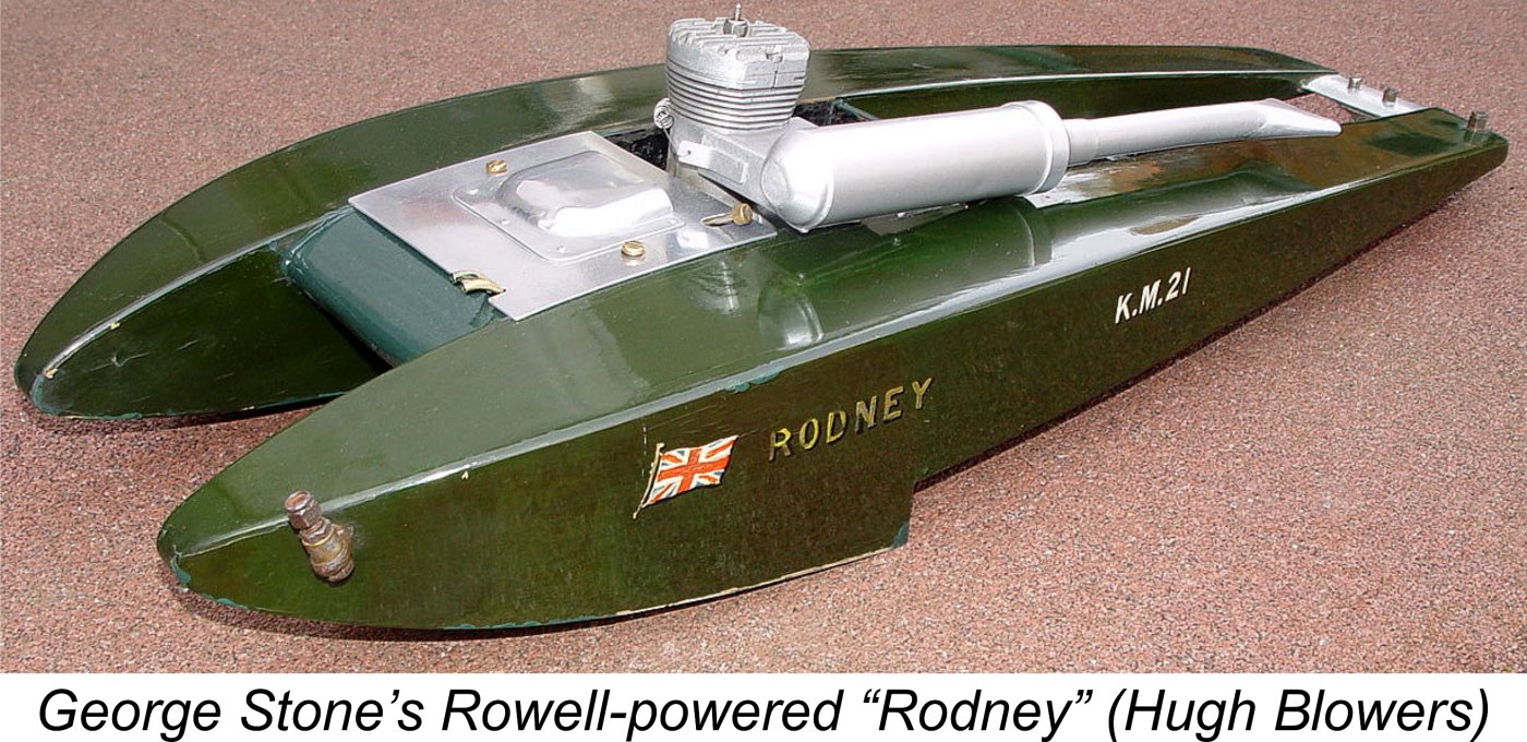 of the American-made Dooling, he fitted a Rowell into his hull "Rodney" in 1950 and issued his "try to beat me with a British motor" challenge. So equipped, "Rodney" achieved a speed of 54.74 mph, backing up Stone's challenge by becoming the fastest British-engined hydroplane at that time, albeit well short of matching the speeds achieved with the Dooling.
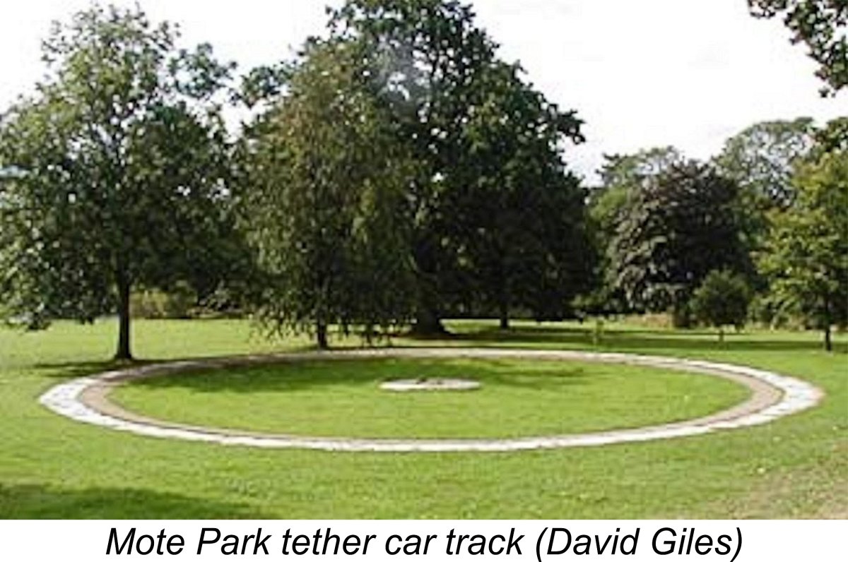

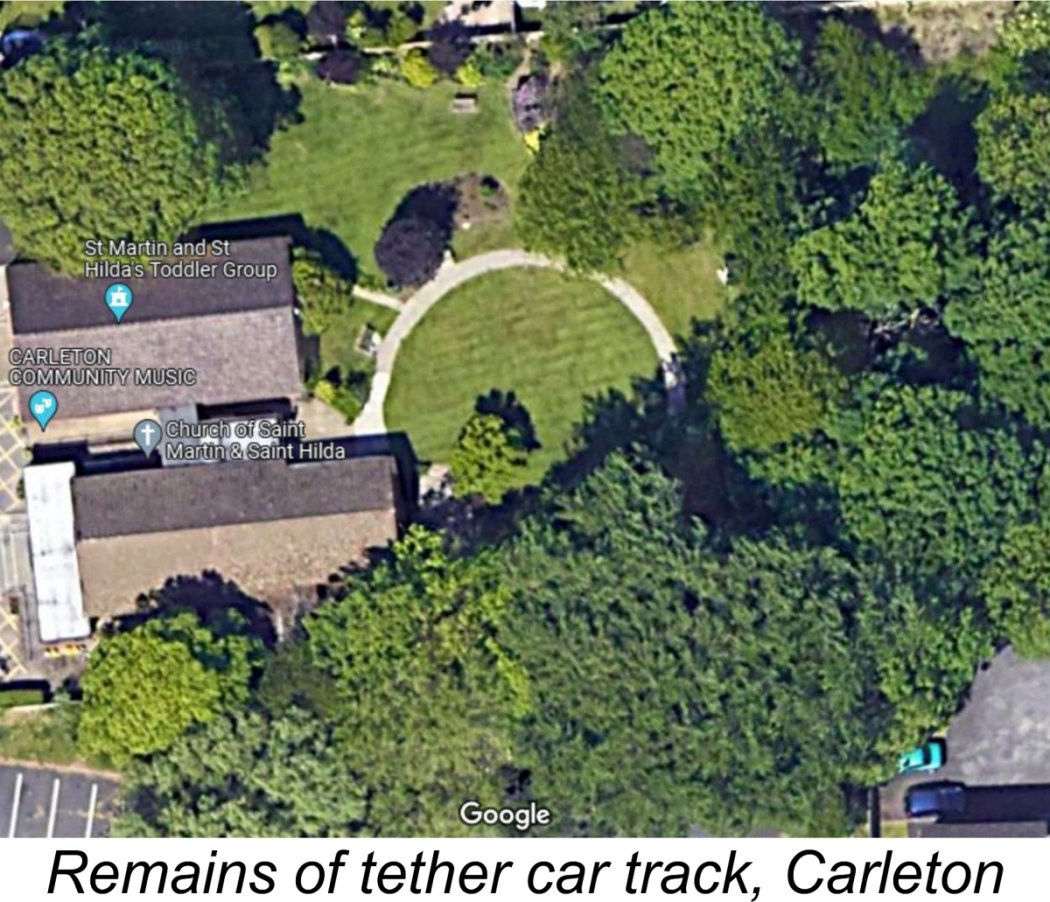
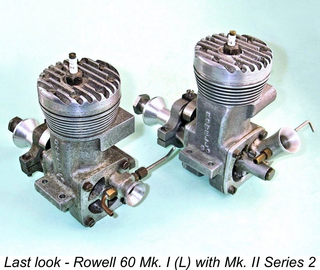 I hope that you've enjoyed this in-depth look at one of the rarer and more exclusive model racing engines of them all. The Rowell 60 was (and is!) a fine engine which did great credit to its designer and manufacturer. Original examples in complete and unmodified condition turn up very seldom these days, and when they do they command some pretty fancy prices. Accordingly, the laws of supply and demand dictate that most enthusiasts will never own one - those of us who do may count ourselves fortunate indeed. However, we can all enjoy contemplating one of the more sincere efforts on the part of a British company to produce a racing engine of real merit. I hope that this article has allowed you to do just that!
| |