
|
|
The Reeves Goblin 2.5 cc diesel
Examples of the Reeves engines are relatively thin on the ground these days. In fact, for many years the two diesel models mentioned above were the sole representatives of the Reeves range in my possession. Next to arrive were nice examples of the two Reeves 6 cc sparkies, which allowed me to expand my coverage to include those models. The acquisition of a nice boxed example of the final model manufactured by Reeves, the ill-fated Goblin diesel of 2.45 cc (0.149 cuin.) displacement, has now allowed me to complete my coverage of the Reeves range on this website by undertaking an in-depth analysis of that model to complement my earlier reviews. My previous articles included summaries of the history of the Reeves range in general. For the convenience of new readers, I’ll begin by repeating that information here. Anyone who is already familiar with this story is invited to skip to the following section of this article. Background The Reeves model aero engines were manufactured on a relatively small scale in Shifnal, a small market town in Shropshire, England. Shifnal lies a little to the south-east of Telford between Wolverhampton and Shrewsbury. The town’s relatively small size may be gauged from the fact that as recently as the time of the 2017 census, its population was still only 7,009 people. It was doubtless considerably smaller in 1946!
No street address was ever given for either location, making it impossible today to identify the former sites with any precision. In any case, the town has changed considerably since WW2 and the two sites have more than likely been re-developed in consequence. There has been speculation in the past that there might have been some kind of family or other connection between the Reeves model engine manufacturing venture and the well-known model engineering supply firm of A. J. Reeves & Co. (now Reeves 2000), which was established just after WW2 at Moseley Road in Birmingham at more or less the same time as Edward Reeves set up shop in not-too-distant Shifnal. However, no less an authority than the late Ron Moulton assured me from his own first-hand knowledge that no such connection existed. Moreover, direct contact with the present operators of A. J. Reeves’ successor company, Reeves 2000, has confirmed that they have no knowledge of any such connection. Case closed in my book .............
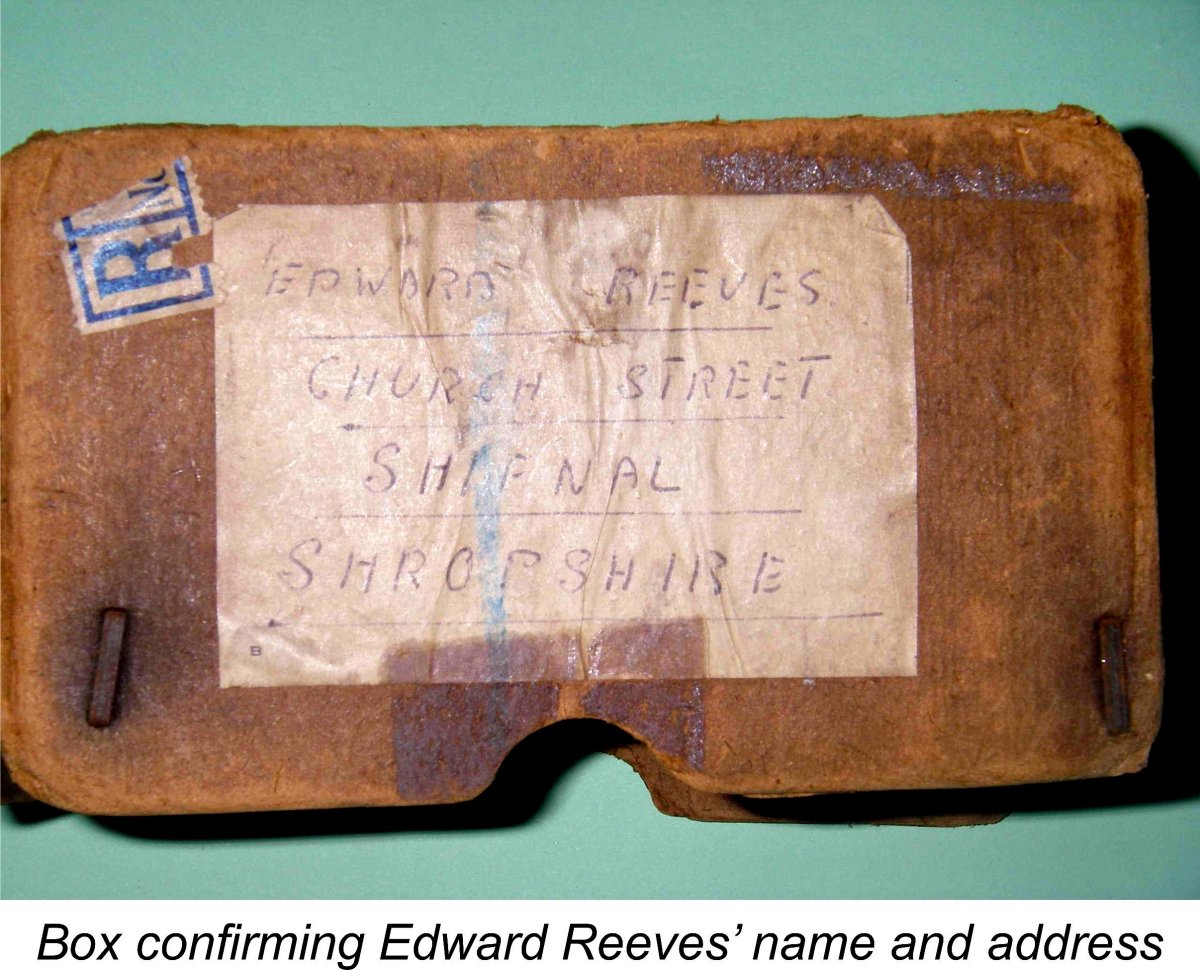
As far as I’ve been able to discover, the first-ever Reeves advertisement appeared in the “Trade” section of the Classified Advertisement feature in the June 1946 issue of “Aeromodeller” magazine, as reproduced at the left. This advertisement offered castings, blueprints and pre-machined components for a spark ignition engine which was available in both 5 cc and 6 cc displacements. A limited number of completed and tested engines were also reportedly available to first-comers. A 10 cc model was said to be in preparation, but there’s currently no evidence that this design ever materialized. The initial advertisement was repeated with minor variations in several subsequent issues of “Aeromodeller”. These advertisements were placed in the name of E. Reeves, Model and Precision Engineers, at the Church Street address. All that is known of this individual is that his name was undoubtedly Edward Reeves – quite apart from a couple of references to him by Peter Chinn, this is confirmed by the address on a surviving box which was used to return a 6 cc petrol engine to the maker for service in 1947. The date is confirmed by a piece of newspaper dated July 4th, 1947 which was used to line the box and is still in it! Many thanks to my good mate Kevin Richards for supplying this valuable piece of evidence!
Like the majority of the small post-war British engine manufacturing ventures having a similar genesis, the Reeves company appears never to have expanded beyond its small-scale artisan beginnings. Low-key grass-roots manufacturing concerns of this type generally followed one of three routes - one, they grew by merging with a competitor (for example, Allbon merging with Davies-Charlton Ltd.); two, they established themselves in a competition market niche based on performance and quality along with the ability to charge accordingly (like Oliver and ETA); or three (and most commonly), they faded relatively quickly from the scene (like Owat, M.S., Majesco, B.M.P., Dyne, Milford, Comet, M.E.C. and Leesil) or moved on to other work (like Rawlings, Yulon and Nordec). Edward Reeves never took advantage of the first possibility, and the second possibility was precluded by the fact that his products were never targeted towards the “performance” market, being very much in the nature of low-key sports engines. Despite this, the Reeves model engine manufacturing venture actually ended up lasting longer than most of the other small-scale independents, staying the course for over 6 years. It's presently unclear whether or not Edward Reeves continued in the precision engineering business after the termination of model engine production, although there are indications that this was his intention. Although he seemingly found it worthwhile to advertise nationally from time to time in the British modelling media, Edward Reeves never achieved the production volumes which would have been required to establish a real presence on the national scene and thus compete with the larger volume manufacturers such as International Model Aircraft (FROG), E.D., Elfin, Mills Brothers and Davies-Charlton/Allbon. Consequently, the Reeves range always remained on the fringes, never attracting much attention from contemporary commentators. Even in their hey-day, such as it was, the Reeves engines constituted something of a “cult” range.
Distinguishing features of this engine included the updraft intake beneath the main bearing; the tall cast iron cylinder with integrally-machined cooling fins; and the bolt-on bypass passage cover and exhaust stack. In his October 1952 test report of our main subject, the Reeves Goblin diesel (see below), Peter Chinn recalled this model from his personal experience as “a sound and likeable spark ignition engine”. A full review and test of this model may be found elsewhere on this website. It is indeed a very servicable unit! As with all Reeves engines, the emphasis in this design was on internal fits rather than external finish. Consequently, despite their somewhat utilitarian appearance the engines quickly acquired a solid reputation for being very well-made and dependable - Chinn’s evaluation was typical. Reeves was to maintain this “care where it counts” philosophy throughout the production life of his range, although as we shall see later he seems to have occasionally dropped the ball.
By 1948 the model diesel was well and truly in the ascendant in Britain, while the appearance of the commercial miniature glow-plug in America had already heralded the beginning of the end for the spark ignition engine both in that country and elsewhere. Edward Reeves clearly recognized this, and it was in 1948 that he took a significant step towards the future by ending production of the trusty 6 cc sparker in favour of his first diesel design, the so-called 3.4 cc model (which actually had a measured displacement of only 3.18 cc!). Although production of the spark-ignition version of the Reeves 6 cc model seems to have ended at this point, it does appear certain that a few examples were produced in glow-plug form. An incomplete and severely battered example of this variant appeared some years ago on eBay. Although the engine was both damaged and far from complete, it was an indisputable fact that there was no provision for a timer, proving the engine’s glow-plug heritage.
As usual with Reeves, the appearance of this engine was lacking in sophistication, with the initial visual impression being that it lay somewhere between the crude side of good and the good side of crude!! However, this impression was quickly dispelled when one handled an example - the internal fits and finishes were beyond reproach. Indeed, it was this model which was the subject of Reeves’ remarkable guarantee to the effect that if an oiled example of one of these engines as delivered failed to hold its compression at top dead centre for a minimum of one hour, the buyer could retain it free of charge!! I can only report that both of my examples still pass this test today, even after an unknown amount of running …………… The Reeves 3.4 diesel was a dependable if unspectacular sports performer by the standards of its day and was quite successful in the sense that the company was apparently able to sell all of its relatively small production. The engine was mentioned in quite favourable terms by Col. C. E. Bowden in the 1949 second edition of his book “Diesel Model Engines”, which can’t have hurt the cause. It was also included in the technical data tables which formed appendices to Ron Warring’s 1949 book “Miniature Aero Motors”.
One other model from this period about which we do know a little was a 4 cc version of the 3.4 which was generally quite similar but was “prettied up” a little and utilized a bolt-on cylinder assembly in place of the former screw-in system. This very rare engine cannot have been made in large numbers - it is almost never encountered today, although examples do exist.
The H.18 was tested by Lawrence Sparey, whose report was published in the March 1951 issue of “Aeromodeller”. Sparey measured an output of 0.1034 BHP @11,700 rpm, figures which are very well supported by my own tests of the engine. Sparey had little but praise for the engine’s design and construction, commenting particularly (and justifiably) upon the outstanding piston-cylinder fit. The H.18 remained in production for some time, still being advertised in “Aeromodeller” in November of 1951. However, by January of 1952 the company was no longer advertising a specific model but was instead hinting at new models to come. By April 1952 these hints had become reality in the form of the 2.5 cc Goblin diesel, another plain-bearing RRV model which was evidently intended to replace the H.18. The balance of this article will focus upon that model. The Reeves Goblin – Description
Like its smaller predecessor, the Goblin was a plain bearing engine, having a crankcase which was generally quite similar in style to that of the H.18. The integrally-cast main bearing housing was unbraced, again like that of the H.18. The Goblin also shared a common material selection, both piston and contra piston being of hardened steel and operating in a hardened steel cylinder liner. The con-rod was also of hardened steel. This material selection was actually a feature of all the Reeves diesels, clearly being a designer preference. It’s worth noting at this point that the use of a hardened steel piston in a hardened steel bore can be a problematic combination, as the makers of the mid-1950’s J.B. engines were to learn to their cost. The problem is that running-in wear is minimal, so the fit and finish have to be pretty near perfect as constructed. There's far less room for error than there is with an iron-and-steel combination, which will wear to a perfect fit even if set up initially a little too tight. Edward Reeves appears to have been an expert at lapping pistons into finely-finished cylinders - my two examples of the 3.4 model as well as my H.18 all have perfectly fitted steel pistons. However, he did sometimes get it wrong - my new and apparently unused example of the Goblin proved to be fitted just that little bit too tightly. Although the cold engine turned over smoothly when oiled, there was a detectable amount of "stiction" above the exhaust port level - the piston tended to stick in the bore when stopped part-way up the compression stroke. The surface finish of both the bore and piston were beyond reproach, but for my money they were fitted a little too closely for an all-steel combination. As we shall see later, such a combination has to be completely free from "stiction" at the outset to work effectively. At this point, the similarities between the Goblin and the H.18 end. In fact, all appearances to the contra The displacement is a little odd, because the manufacturers always referred to the Goblin as the "Reeves Goblin 2.49 cc racing diesel engine". Perhaps the workshop abacus was playing up that day ....... the characterization of the engine as a "racing" unit is also a little strange given the absence of ball races. However, it must be admitted that in other respects the engine does largely follow the established "racing" layout exemplified by such contemporary designs as the E.D. Mk. III Racer. Further differences are to be seen in the design and installation of the cylinder. The H.18 used a drop-in cylinder liner along with a cooling jacket which was formed integrally with the main crankcase casting. The liner was retained by the cylinder head, which was attached using three screws. By contrast, the Goblin employs an AMCO-style screw-in cylinder along with a screw-on cast alloy cooling jacket. The Goblin's twin exhaust stacks appear at first glance to be cast integrally with the main crankcase casting. In reality, they are a single separate cast alloy component which is held in place by the screw-in cylinder assembly. The engine can readily be operated with these stacks removed if desired.
By contrast, the Goblin uses "360 degree" annular transfer and exhaust porting, with four milled exhaust slots and four milled transfer slots having narow pillars of metal separating them. This was actually the feature which allowed the Goblin to be constructed using screw-in cylinder components. Although the annular orientation of a screw-in cylinder when tightened cannot be guaranteed, the final orientation theoretically makes relatively little difference to performance when annular porting is employed. The arrangement used in the H.18 did have the advantage of allowing for the transfer port to overlap the exhaust almost completely, giving a very short blow-down period. However, there was only one modestly-dimensioned transfer port which was fed by a single bypass passage of rather limited area at the front of the upper crankcase. From a gas flow standpoint, this arrangement was less than optimal - the lower entry into the bypass passage was encumbered both by the full-disc crankweb and by the piston skirt at and near bottom dead centre. The radial annular porting used in the Goblin represents a trade-off - overlap sacrificed for area and accessibility. Although it's impossible to provide any overlap with this type of porting, total port areas may be quite large. This type of porting had become very popular and successful by the time of the Goblin's introduction. Indeed, with its annular porting and disc valve induction, the Goblin was in most respects a very up-to-date design by 1952 standards. Like all engines utilizing this type of cylinder porting, the Goblin's port timing was very much a compromise forced upon the designer by the need to allow for an adequate transfer period. The exhaust ports open very early at only 100 degrees after top dead centre (ATDC) for an exhaust period of 160 degrees. The transfer ports open some 30 degrees later for a transfer period of 100 degrees. Overall, these figures appear to represent an excessively long exhaust period allied to a shorter than ideal transfer period.
The hardened steel crankshaft is a one-piece component having a counterbalanced full-disc crankweb, like its H.18 predecessor. It is extremely well finished and fitted. It must be admitted however that this component seems very much on the skimpy side for a diesel engine of this displacement. It has a main journal diameter of only 0.250 inch, which is itself a bit on the marginal side to start with. It's true that a number of successful 2.5 cc designs from other makers (such as the E.D. Mk. III Racer and the D-C Rapier) had shafts of this diameter, but their shafts were extremely well supported in ball races. Moreover, in the case of the Reeves the already somewhat marginal situation was further aggravated by the designer's decision to drill out the centre of the shaft at a diameter of 0.157 inch, presumably to lighten the engine albeit at some cost in terms of increased crankcase volume with consequently reduced crankcase pumping efficiency. The E.D. and D-C shafts mentioned above were not lightened in this manner. Admittedly the Goblin's shaft is not saddled with an induction port which would act as a stress-raiser, but even so the resulting wall thickness of only 0.047 in. (1.19 mm) seems to me to be very much on the inadequate side. Indeed, there is documentary confirmation that this view is not unfounded, as we shall see in due course. A quick calculation shows that the drilling-out of the shaft reduces its cross-sectional area by some 39% - somewhat less than I would have expected, but still very significant, especially when it comes to resisting shear stresses. I would definitely prefer to have that extra metal there to resist cyclic shear and bending stresses. We will have occasion to recall this comment in a later section of this article. The one positive aspect of the drilling-out of the shaft was the fact that a tiny hole was cross-drilled into it part way along the journal to improve the supply of lubricant to the rather long plain bearing.
It seems clear that Edward Reeves had recognized this limitation by the time that he got around to designing the Goblin. The cast alloy backplate on the latter model features an inlet tract which is formed as cast to delay the closure of the induction phase considerably. The measured timing on my example of the Goblin is from approximately 40 degrees after bottom dead centre to 40 degrees after top dead centre, quite rational figures which yield a total induction period of some 180 degrees. This is a considerable functional improvement over the design of the H.18. The fact that the cast alloy disc is counterbalanced also represents a step forward. Like that of the H.18, the backplate of the Goblin is secured using three countersunk machine screws. This inspires a word of warning - if you ever acquire one of these engines, do not over-tighten these screws! The wedging action of the countersunk head could easily split the rather flimsy "mouse ear" lugs on the backplate. The rest of the engine is pretty much identical in concept to that of the H.18, with no particularly remarkable features to be noted. In common with all of my Reeves engines, all fits and tolerances in this particular example are extremely close, with ultra-fine surface finishes on all working parts.
It seems likely that all of these engines were similarly numbered. If any reader has additional serial numbers to share, I’d be delighted to hear from you! The key question to be answered is whether or not the sequence started at B1 or The engines were supplied in sturdy and clearly-labelled cardboard boxes, complete with a guarantee slip, a concise but well-written and informative set of instructions and a test card showing the starting settings supposedly determined during the engine's factory test run. The recommended fuel was a mixture of equal parts of paraffin (kerosene) and heavy engine oil of unspecified type, to which between one and two parts of ether were to be added at the user’s discretion. A running-in period of one hour on the bench was suggested. Recommended airscrews were 9x6 for running-in and free flight use, 9x6 or 8x8 for control-line stunt and 9x9 for control line speed work. It must be said that these sizes appear excessive for an engine of this specification and displacement, and indeed Peter Chinn mentioned in his published test (see below) that he found it necessary to use somewhat smaller sizes to achieve anything approaching peak performance. The Reeves Goblin on Contemporary Test As stated earlier, the Reeves Goblin was to all appearances a thoroughly up-to-date design by 1952 standards with its disc valve induction and its well-developed annular porting. Accordingly, it was scarcely surprising that the engine soon attracted the attention of the resident engine guru at “Model Aircraft”, the ever-informative Peter Chinn, who first noted the "recent addition" of the Goblin to the 2.5 cc class in his "Accent on Power" column in the September 1952 issue of "Model Aircraft". Chinn's unattributed test of the engine subsequently appeared in the October 1952 issue of the magazine. Unfortunately, this test seems to have played a significant role in bringing about the demise of the Reeves range in general and the Goblin in particular.
However, that was about it as far as positive comments were concerned. Chinn began by commenting upon the rather rough finish of the cast alloy cooling jacket. This was the least of the problems, though – a far more significant criticism was an excessively loose contra-piston which actually hammered up and down in the cylinder at the lower speeds. The engine would not hold its compression settings as a result, although this problem reportedly diminished at the higher compression settings required to achieve higher operating speeds, along with more elevated operating temperatures. It’s worth noting in passing that the use of hardened steel for the contra piston may have had much to do with this behaviour. A steel contra piston operating in a steel bore has a well-recognized tendency to freeze in the bore when the engine gets really hot. Consequently, engines featuring this material specification not infrequently have rather loose contra pistons when cold. My Reeves H.18 has such a contra-piston, which feels a little slack when the engine is cold but expands to a perfect fit when hot, never sticking in the bore while holding its settings perfectly.
But the worst was saved for last. Chinn had to report that he was unable to complete his performance evaluation due to the fact that while the engine was running at 11,000 rpm the crankshaft sheared through immediately forward of the crankweb. This failure naturally precluded the measurement of any performance figures at higher speeds, also preventing Chinn from following his usual procedure of re-checking the figures obtained on the initial series of tests. According to Chinn’s test report, the engine survived only one hour of running time before this failure occurred. Once again, Chinn did his best to be fair to the manufacturers. He attempted to contact them, both to discuss this failure (which should have been covered by the sixty-day materials and workmanship guarantee with which the engines were supplied) and to obtain either a replacement crankshaft or another example of the engine for re-test. However, he had to report that his efforts to contact the manufacturers had been unsuccessful, implying that Edward Reeves may already have been winding up his involvement with model engine manufacture as of the second half of 1952 after making a limited number of examples of the Goblin earlier in the year. The best that Chinn could do under these circumstances was to state that the engine was delivering some 0.17 BHP at 11,000 rpm when the failure occurred.
Although Chinn exercised his usual professional restraint throughout, this report must have done much to seal the fate of the engine in the marketplace. You had to look hard to find a Reeves engine to buy at the best of times, and it would appear that after reading this test report people stopped looking ................... This was a pity, because the Goblin was an interesting design with plenty of development potential which was in many ways a quite attractive unit. Moreover, it must be said that the basic design of the engine seems sound enough - elimination of the central drilling of the crankshaft was probably all that would have been required to create a perfectly sound and dependable unit. Even without that modification, the fact that a limited number of used examples still survive intact today indicates that they didn’t all suffer the fate of Chinn’s example - indeed, Chinn himself expressed the opinion that he had simply got a flawed example of the engine. This view is supported by the fact that in his 1977 “Collector’s Guide to Model Aero Engines” the late O. F. W Fisher recalled using the Goblin to power a three-engined helicopter!! Seemingly he at least got the engines to work OK! Reeves Finally Responds Although Chinn had not received a response to his crankshaft inquiry by the time when he completed his test report on the Goblin (probably early September 1952 allowing for Editorial lead time), the manufacturer eventually did make contact with the magazine. Appended in very fine print to the end of the test of the OK Cub .049 glow which appeared in the December 1952 issue of “Model Aircraft” was the following statement: “We have now heard from the manufacturers of the Reeves Goblin engine, featured in the October issue, which, it will be recalled, suffered a shaft failure. The manufacturers state that this was due to incorrect hardening of the crankshaft. The hardening, which incidentally is not carried out by Messrs. Reeves Engineering Co. themselves, had been made too deep, and since the Goblin shaft is hollow and of moderate thickness, this had resulted in its becoming brittle and failing under severe test. The makers state in fact that they themselves experienced a number of shaft breakages and that following this they had scrapped the batch of crankshafts from which the defective ones were taken. Unfortunately, it appears that our test engine escaped unnoticed. The makers have however offered to replace the defective shaft. The Reeves Goblin featured in our test is shortly to be superseded by an improved “Mk. 2” model which it is hoped to include in the Engine Test series at a later date”. I’m uncertain about what to make of this. There’s no evidence that the cited Mk. 2 version of the Goblin ever appeared. It’s also strange that Reeves delayed for so long in responding to Peter Chinn’s request for a comment. A timely response to his inquiry in advance of the test's publication would have done much to minimize the impact of the failure. To me, this looks like a last-ditch attempt to rehabilitate the Goblin’s reputation in order to facilitate the liquidation of existing unsold stocks of the engine. If so, it almost certainly made no difference – probably very few readers actually read the fine-printed comment! More on this topic in its place below. The Reeves Goblin Re-Appraised The fact that my Goblin was clearly a very late example led me to believe that it might well have one of the cited improved shafts, hence more than likely being able to survive a test at my hands provided that I exercised perhaps even a higher level of care than usual when running an engine of this rarity. All of my other Reeves diesels had come through their tests with flying colours, and I saw no intrinsic reason to believe that the Goblin would do any less, particulaly if it had a properly heat-treated shaft. Accordingly, I decided to go ahead with a limited test of this interesting engine.
I was also confident that a new stronger shaft could be made if required, although I sincerely hoped that this would not be necessary. Accordingly, I resolved to conduct the test in as cautious a manner as possible, avoiding over-compression like the plague and keeping the total amount of accumulated running time down to a maximum of 40 minutes, whatever the results. Although this example appeared to be new and unrun apart from its presumed factory test, all surface finishes were so good that I saw no reason to go to the full one-hour break-in recommended by the manufacturer. The one potential issue was the slightly sticky piston/cylinder fit - this would clearly affect the engine's performance. However, with an all-hardened steel combination it would probably take more running time than I was prepared to invest to free things up significantly. In any case, a hardened steel piston does not require the heat cycles which are so essential to the running-in of a cast iron piston. I therefore decided in advance to limit the running-in period to twenty minutes, after which I would make a short series of brief test runs to get some idea of the engine's performance potential at that stage. I might not realize the Goblin's full potential with this amount of running, but I would hopefully at least be able to test Chinn's earlier findings. I also decided in advance that rather than taking readings for a pre-determined range of test props and then subsequently analysing the data, I would calculate the indicated output at each speed tested on the spot before moving to the next lighter load. In this way, I would become aware immediately of the point at which I had passed the engine's peak. I would end the test that point, thus minimizing the required running time and avoiding unproductive over-speeding. Finally, I also decided to use a lightweight prop for the break-in period. This decision stemmed from a line of reasoning which seems to be worth repeating here. It should be obvious that the crankshaft of a single-cylinder two-stroke model engine is only being powered at most for around one-third of a complete revolution. The rest of the time, the shaft is being turned by the angular momentum of the airscrew. There is thus a cyclic reversal of torque-related stress over the course of a single revolution of the shaft. This fluctuation in torque has the effect of causing the prop to turn at a slightly uneven speed - it is accelerated on the power stroke and slowed during the compression stroke. When the engine fires, the force generated by gas pressure upon the piston acts upon the crankpin to generate torque in the shaft, thus turning it. This torque will be applied in the direction of rotation viewed from the rear. Naturally the prop resists this torque, absorbing it both aerodynamically and in part by accelerating during the power stroke, thus gaining the extra angular momentum needed to carry it and the other working components through the un-powered balance of the revolution, including the compression phase. Indeed, once the power stroke ends, the accumulated angular momentum of the prop is all that's available to keep the shaft turning over. In particular, the prop has to apply sufficient torque to the shaft to overcome the very considerable resistance of compression allied to a tight piston fit. A moment's thought should convince the reader that this resistance sets up a torque in the shaft which is opposite to the direction of rotation, thus representing a reversal of the torque experienced by the shaft. A classic stress reversal situation - an essential element of any fatigue failure of the material involved. Now here's the crux of the argument. At any given sp The result will be that with a lighter prop the shaft will experience a reduced magnitude of cyclic stress reversal, albeit at the cost of an increased rate of cyclic acceleration and deceleration. For our purposes, the key factor is the cyclic stress reversal - when dealing with a shaft of questionable structural integrity, the use of a lighter prop will tend to reduce the magnitude of this reversal. A good point to recall when testing any engine of doubtful structural integrity. Taking this argument into account, I settled upon a carefully-balanced BY&O 9x4 wood airscrew, which is a "slow" wide-bladed 9x4 weighing only 11 gm as opposed to the 22 gm of the APC glass-reinforced nylon item that I would otherwise have used. Using this prop and exercising judicious use of the compression control would hopefully do much to reduce stress on the shaft during the planned 20-minute break-in period. After that, I would just have to hope that the short-term use of standard test props did not create a problem.
In fairness to Edward Reeves in view of the earlier criticism regarding the piston fit, I have to admit that when lubricated with the oily castor-based fuel which I was using, the engine felt pretty good. Much (but not all) of the "stiction" detected previously had disappeared, allowing the engine to turn over quite smoothly when flicked. Naturally with such a close-fitting piston, compression seal was outstanding - you could probably set the thing at top dead centre, go off for lunch and come back to find it still holding the compressed gas! Based on the engine's "feel" at this stage, Reeves probably felt that he had achieved a perfect fit. However, the proof of the pudding is in the eating! The first issue that I encountered was the fact that as received, the compression setting of this apparently new-in-box engine was way too low for starting - far too low in fact to be accounted for by the use of different fuel. I actually had to increase compression by over 1½ turns of the comp screw to get any kind of a firing reaction. I will admit to being very puzzled indeed by this observation. Engines which are test-run at the factory (as this one was claimed to be) are generally left at their test settings when packaged for shipment and sale. There's no doubt at all that this example was never tested at the supplied setting, either by the manufacturer or by a subsequent owner. One might suspect that the setting had been altered by a previous owner, but doing so would require that the engine be dismantled and the contra-piston pushed up in the bore. Any rational motivation for such an action with a new engine is difficult to discern.
Taking the above observations into account as well as additional evidence to be discussed below, I must admit to having considerable doubt that this engine was actually test-run at the factory as claimed. We'll consider the possible implications of this in a subsequent section of this article. Although the instruction sheet claimed that choking alone would induce sufficient fuel into the engine to achieve a start, I found that it was very easy to flood the crankcase using that approach. I ended up using a single choked flick to fill the fuel line, followed by a small exhaust prime. Once correctly set, the engine started very easily indeed using this procedure.
The fact that the problem was a tightening piston became very apparent when one turned the engine over immediately after it stopped - the dreaded "stiction" was back in full force! The engine never actually seized - rather, the piston expanded within the bore to the point where friction power losses and associated heating overloaded the system to the point where the engine could no longer keep running. Once the engine cooled down completely, happiness was restored - the engine felt fine once more and was very easy to re-start. But the same problem persisted - it was impossible to run the engine for any length of time at anything approaching an optimum setting. The sequence of events was very clear. The fit when cold was very close indeed, which naturally made for very good starting. Once running, however, the piston heated up more rapidly than the cylinder, since its exposed heating surface at ignition was greater and it was not directly exposed to the cooling airflow. Since its coefficient of thermal expansion was the same as that of the cylinder (both components being of hardened steel), this caused it to tighten slightly in the bore. Now a vicious cycle began - the tightening of the piston created additional heat as a result of the added friction. The piston was less well able to dissipate this heat than the cylinder, with the result that the temperature differential between the two components widened. This caused the piston to tighten still further, creating even more heating, and the cycle continued until the friction of the ever-tightening piston stopped the engine. Here we see a perfect example of the reason why a hardened steel piston working in a hardened steel bore is not a particularly good idea. If the fit is perfect as constructed, all should be well and you'll have a really long-wearing set-up. But if it's even slightly too tight, as in this case, merely running the engine in won't solve the problem, since running-in wear will be minimal. In fact, by the time the piston/cylinder fit is eased to perfection, the rest of the engine will either have failed or become worn out! The only short-term fix for this problem would be to intervene in order to create a slightly looser fit of the piston in the bore. This would require dismantling it to lap a little out of the bore, thus easing the piston fit, or (perhaps better yet) making a new piston out of cast iron. As matters stood, I chose to continue testing the engine as delivered by the manufacturer. I soon settled into a routine which I hoped might ease things a little. I would start the engine and let it run for a couple of minutes a bit rich and slightly undercompressed. It would keep running OK under those conditions. I would then try to pick things up by leaning out the mixture and increasing compression. The engine would pick up nicely, with very smooth running, but would quickly begin the sagging cycle noted earlier. At that point, I would stop it by pinching off the fuel line. I would then allow complete cooling before repeating the process.
I found that the contra-piston in this example was perfectly fitted. It felt a touch looser than usual when cold (exactly like my Reeves H.18), but tightened to an ideal fit once warmed up - typical of a hardened steel component in a steel cylinder. It held its setting very securely at all times while never showing the slightest tendency to stick in the bore. What a pity that the same couldn't be said for the working piston! Another welcome finding was the fact that the cylinder assembly showed no signs of unscrewing at any time. This is a chronic fault of many engines having screw-in components. I had not disturbed the factory assembly, which held firm throughout the test. After my planned 20 minutes of running in this manner, things had improved marginally - the engine would rev out reasonably well for a short period of time on a slightly rich needle, but leaning it out all the way immediately initiated the heat/sag cycle described earlier. I actually departed from my original plan by putting on a further ten minutes, just to gauge the effect. Sadly, there was little detectable improvement over this period. It was becoming apparent that it would take far more running-in time than I was prepared to risk to free things up to the point where steady leaned-out running could be achieved. Since I was now closing in on my self-imposed 40 minute running time allocation, I decided to try to obtain a few figures for a number of test props. My approach was to start with the engine completely cold, get it going and adjust as quickly as possible for best running. Then I immediately obtained a speed reading before the sagging cycle really set in. As soon as I had a reading, I stopped the engine. It should be clear from this description that the very ordinary results which I obtained in this way represent the minimum that this design can achieve. In reality, by the time I hit maximum revs, I only had a few seconds before the sagging became problematic. Even before that point, the friction losses must already have been building up. As a result, I had absolutely no doubt at all that the engine would better the figures reported below by a considerable margin if it was properly fitted. For what they're worth, here are the spot-checked best speeds obtained with the various props tested, together with the partial power curve derived from those figures:
It's clear that I didn't reach the engine's peak, such as it was under the test conditions. The problem was that the Goblin was so reluctant to run "flat out" that there was clearly no possibility of extracting a truly representative performance from it. For that reason, I saw little point in continuing, especially since the figures that I was getting were obviously well below the engine's potential. I was also past the 40 minute running period that I had allocated for the test, and the engine was still in one piece. A good excuse for quitting while I was ahead! I put on one more run on the BY&O 9x4 to see if things had improved at all with a few faster runs. Finding that they hadn't, I terminated the testing.
I was objectively certain that my engine would at least equal Chinn's figures if it was properly freed up. Indeed, the functional design of the Goblin seems pretty sound in performance terms - based upon years of experience, I would certainly expect a well-fitted example to get past 0.200 BHP and peak at around 12,000 rpm or so. That kind of potential seems to be there in the design. For the moment, I had to leave it at that. Overall, my experience left me with an impression that things were going downhill somewhat at the Reeves manufacturing facility during the Goblin era. For one thing, there seems to be a strong possibility that my example never actually got a test-run at the factory despite the manufacturer's assertion - if it had, the problem with the excessively tight piston would have become glaringly apparent, making the need for corrective action prior to sale quite unmistakable. Moreover, there was absolutely no trace of castor oil residue. The issues of the incorrect compression setting and inappropriate recommended needle setting heighten this impression still further. It appears that corners may have been cut, with highly detrimental effects upon quality control............. In terms of the engine's design, several legitimate criticisms may be made. First, the shaft is undeniably under-nourished for an engine of this displacement. A modest increase in main journal diameter together with elimination of the central drilling would probably have done much to ensure the engine's dependability and longevity, also conferring the benefit of a reduction in crankcase volume. There would of course be a weight penalty, but I would readily trade that for greater structural integrity and the greater pumping efficiency resulting from a substantially reduced crankcase volume. A larger-diameter shaft would doubtless impose elevated levels of viscous drag, but I would expect the consequences of this to be minimal. Another major design issue is the lack of bracing on the main bearing housing. As designed, this portion of the engine looks as if a hard crash could easily cause a fracture at the point where the housing joins the main crankcase. I would have made it to a larger outside diameter, perhaps also externally expanding it in taper fashion towards the front of the crankcase. Again, the weight penalty would be minimal. Finally, I would definitely have preferred to see the piston made of cast iron instead of hardened steel. A cast iron piston would soon run in to a perfect fit even if assembled a little too tightly initially. The present design specification would be fine if perfectly fitted at the factory, but the slightest error (which is all that my example exhibited) is enough to render the engine practically unuseable. I'd sum up the Goblin as a basically sound and well-made design in purely functional terms, but one in which a number of key design dimensions and material specifications urgently required reconsideration. Perhaps if the company had continued in business, we might have seen such an improved model. However, events overtook any such intentions, as we shall see in a subsequent section of this article. But before going there, it may be instructive to give further consideration to the kinds of modifications which might have resolved the Goblin's problems. The Goblin as it Should Have Been
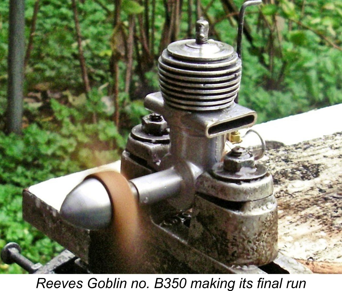
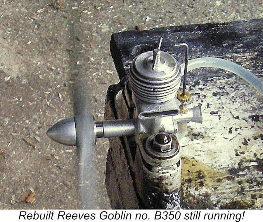
To this end, I approached my good mate Dean Clarke of New Zealand, owner of the Cre8tionworx workshop which produces limited numbers of extremely high quality model engines. As it turned out, Dean had already been entertaining notions of producing a limited series of Reeves Goblin replicas. Correcting the deficiencies in my engine would give him the opportunity to take measurements and finalize the design for his replica series. An obvious win-win here! So Goblin no. B350 made the long journey down to New Zealand, where Dean made a new stronger shaft without the oversized central drilling and produced a properly-fitted cast iron piston together with a light Upon its return to Canada, it didn't take me long to get the refurbished Goblin into the test stand. Since all of its working components had been replaced, it was clear that a full break-in would be required prior to any testing being done. For this purpose, I elected to used the BY&O 9x4 wood airscrew that I had tried earlier prior to the rebuild. I quickly found that the engine's starting and handling characteristics had been unaffected by Dean's modifications. Consequently, I experienced little difficulty in putting on a series of slightly rich and under-compressed 5 minute runs, leaning out briefly at the end and then allowing complete cooling prior to a re-start. The engine showed no signs of nipping up when leaned out, while the fact that it spun the BY&O 9x4 prop at 9,700 rpm during its leaned-out bursts represented a huge improvement over the 7,600 rpm measured earlier prior to the rebuild. Encouraging! Once I judged that the break-in was complete, I tested the engine on a series of my calibrated test props, allowing complete cooling between runs to continue the series of heat cycles which constitute a major element of a proper break-in. The following data were measured:
The APC 7x6 WB is a wide-blade prop created by cutting down a standard APC 8x6 to fill a gap in the power absorption coefficients in my test prop series. As the data demonstrate, it was this prop that came closest to the engine's peak output. The rebuilt Goblin was quite happy to run fully leaned out for as long as required - the former sagging issue was completely absent, with running being completely smooth and mis-free. I had no difficulty in establishing a peak output of 0.221 BHP @ 11,200 rpm. This is well above the implied outputs suggested by Although the reduced internal friction resulting from the improved piston/cylinder fit at operating temperatures doubtless made a substantial contribution, I would guess that this improvement in torque development was due at least in part to the reduced crankcase volume resulting from the elimination of the central drilling in the crankshaft. The fact that the engine's peaking speed was not extended suggests that the limiting factors may be either the engine's bypass system or its cylinder port timing figures - perhaps a combination of both. That said, the engine still has some freeing-up potential. I suspect that some further running would result in a modest increase in its peaking speed and associated power output. Even as things stand, the performance of the rebuilt Goblin was pretty much in line with that of other plain bearing 2.5 cc diesels as of 1952. In February 1951 Peter Chinn reported an output of 0.16 BHP @ 10,500 rpm for the FROG 250, while in September of that same year he found a peak output of 0.21 BHP @ 12,000 rpm for the 1950/51 Elfin 249 PB model. Even as late as June 1955, Chinn reported an output of 0.22 BHP @ 12,750 rpm for the A-M 25 Mk. I of late 1954, two years after the Goblin had disappeared. It's clear that in performance terms, a Goblin built to the more appropriate specifications embodied in Dean Clarke's rebuild would have been positioned well within the mix of plain bearing 2.5 cc diesels as of 1952. The Reeves Goblin Replicas
Dean's plans actually went well beyond the release of a straightforward Goblin replica. In the end, he released three distinct versions of the Goblin. The first was a faithful replica of the plain bearing original, albeit with a few internal design shortcomings of the original Reeves production addressed on the basis of lessons learned from my example. There was also a second slightly hotted-up version featuring a twin ball-race (TBR) crankshaft - perhaps the Goblin as it should have been! As if this wasn't enough, Dean also developed a design for a crankshaft front rotary valve TBR unit somewhat more loosely based on the Goblin. Videos of all three variants running may be viewed at this location. End of the Line Considerable uncertainty surrounds the circumstances under which the Reeves model engine range came to an end. The previously-noted fact that in or around August 1952 (taking account of his editorial deadline for the October issue) Peter Chinn could not establish contact with Edward Reeves in connection with his test of the Goblin implies that the manufacturer was very likely already in the process of winding up his involvement with model engine production at that time. A straw in the wind in this regard is the previously–noted company name-change from Reeves Model Power Units to Reeves Engineering Co., which seems to have taken place at some point in or around mid 1952. The box with my own example of the Goblin (no. B350) bears the latter company name, almost certainly implying that it is a relatively late example of the engine. The elimination of any reference to model powerplants in the new company name would appear to suggest that Edward Reeves had plans to re-direct his energies into broader fields of precision engineering. There seem to be two possible explanations for such a decision. The first of these stems from the fact that, contrary to seemingly widespread belief at the time, the profit margin associated with model engine manufacture was never large due to the very high standards of care and precision required as well as the small and hence “fiddly” size of the individual components. Edward Reeves may simply have seen more money to be made in other fields. Indeed, this completely rational decision may well have pre-dated the appearance of Peter Chinn's test of the Goblin which pretty much sealed the fate of the Reeves model engine range. That said, the somewhat clouded circumstances surrounding the end of the range give rise to another possibility which must be considered. Before I delve into this possibility, I need to say in fairness to the manufacturer that it's very difficult for me to believe that he would not have undertaken sufficient bench and field testing at the pre-release stage to confirm that he had a dependable design. If he did indeed do so with positive results, then the crankshaft problem encountered by Chinn and the excessively tight piston in my example were nothing more than individual defects with those particular engines. There have been many other examples of such issues arising with other models. Indeed, the manufacturer's comment published in the December 1952 issue of "Model Aircraft" claimed specifically that this was the case.
Well, here's a possibility to consider! If a significant number of the Goblins that were sold following the engine's release broke their shafts in service within sixty days, Edward Reeves would have been inundated with claims under warranty. Worse yet, in such a case the provision of a replacement from available stock would not resolve the matter, since only a basic design flaw could explain a chronic tendency for the shafts to fail. In such a case, the replacement shaft would simply break in turn. The only fix would be to drop everything and spend a good deal of unpaid time making a batch of new stronger shafts without the central drilling. As an experienced model engine manufacturer, Edward Reeves would surely have recognized this immediately. Under such circumstances, it may have seemed expedient (if not exactly ethical) to duck below the radar and ignore the claims while making immediate plans to re-focus the successor company's efforts into other fields. This would explain Chinn's inability to contact the manufacturer during the course of his test, even though Reeves seems to have continued trading until the end of 1952.
This final advertisement is significant insofar as it "announces" the engine then on offer as being the “New Goblin Mk. II” 2.49 cc diesel. It would appear that Reeves had come to the realization that no-one was going to invest in the original model of the Goblin and that the only chance of selling more engines was to market them as re-designed Mk. II units. At this point I may as well come right out and say that I am currently unaware of any evidence whatsoever that such a model ever existed! There don't appear to be any surviving examples - at the very least, none have been reported. Moreover, if an improved variant did exist, surely an example would have been sent to Peter Chinn to allow him the opportunity to comment on the design revisions? As it was, even the illustration which was included in that advertisement showed the original model rather than any new and improved version. If a new and revised model actually existed, surely it would have been illustrated to drive the point home? It’s an almost inescapable conclusion that the engines on offer were actually unsold examples of the original model and that this was an attempt to imply that the engine had been re-designed to address the issues raised in Peter Chinn’s test. Once again, the ethics of such an approach are wide open to question. In one other respect, the wording of this final advertisement was potentially somewhat misleading. At first glance, it appeared that the selling price of the "new" offering had been reduced from £3 10s 0d (£3.50) to only £2 16s 0d (£2.80). However, a close look at the fine print reveals that this quoted price did not include 14 shillings (£0.70) Purchase Tax, which had been included in the previous quote. Add that in, and the real price (to British customers) was right back at the earlier figure of £3 10s 0d (£3.50)! Seemingly this was intended to imply a price reduction which did not actually exist............. All of this makes it appear highly likely that this was simply an attempt to recover tied-up capital by selling off existing stocks of the original model, taking advantage of the 1952 Christmas rush to do so. If (and only if) this scenario is correct, and particularly if there never was a Goblin Mk. II model, then it must be admitted that the demise of the Reeves range was clouded by some rather questionable marketing strategy. Edward Reeves would have been passing off a model which he knew to be potentially flawed as a redesigned unit in which the earlier problems had implicitly been addressed. Worse yet, he would already have been well into the planned change of business focus, hence having neither the ability nor the intention of honoring the sixty-day guarantee with which the engines were still supplied. Chinn's experience confirms at least that much. Regardless of how it came about, that December 1952 advertisement was the last that was to be heard of the Reeves model engine line. I have been unable to discover anything about Edward Reeves' further endevours. If any reader has knowledge of this, please get in touch! Conclusion
Sadly, by the time Reeves came up with first the H.18 and then the Goblin, other circumstances arose which forced him out of the model engine manufacturing business. A great pity - it would have been very interesting to see where the Reeves range might have gone next ......... Still, a range well worth remembering! If you ever get a chance to acquire an example of a Reeves engine, don’t hesitate – you’ll enjoy the experience!! Just look after that flimsy Goblin crankshaft ......or get a replacement made! _______________________________ Article © Adrian C. Duncan, Coquitlam, BC, Canada First published April 2024
|
||
 In previous articles which may be found here, I've recounted the story of several of the rather obscure model engine designs which were manufactured in somewhat limited numbers between 1946 and 1952 by Edward Reeves of Shifnal in Shropshire, England. This coverage has included in-depth reviews of the
  The Reeves company traded initially under the name of E. Reeves, Model and Precision Engineers, working from an address on Church Street in Shifnal. The company name was later changed to Reeves Model Power Units, along with a concurrent change of address to nearby Victoria Road. The latter is now part of the A464, constituting one of the main thoroughfares passing through the community. A final name change appears to have occurred in mid 1952, when the company began to identify itself as Reeves Engineering Co., still on Victoria Road.
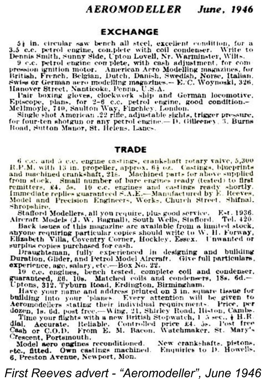
 The manufacturer’s initial address was simply given as Church Street in Shifnal. No street address was used, presumably because (in typical British small-town fashion at the time) Edward Reeves was evidently sufficiently well known as a resident of Church Street to ensure correct delivery without a number. The move to nearby Victoria Road must have come at some later point in time, certainly by 1949 if the advertising is anything to go by.
 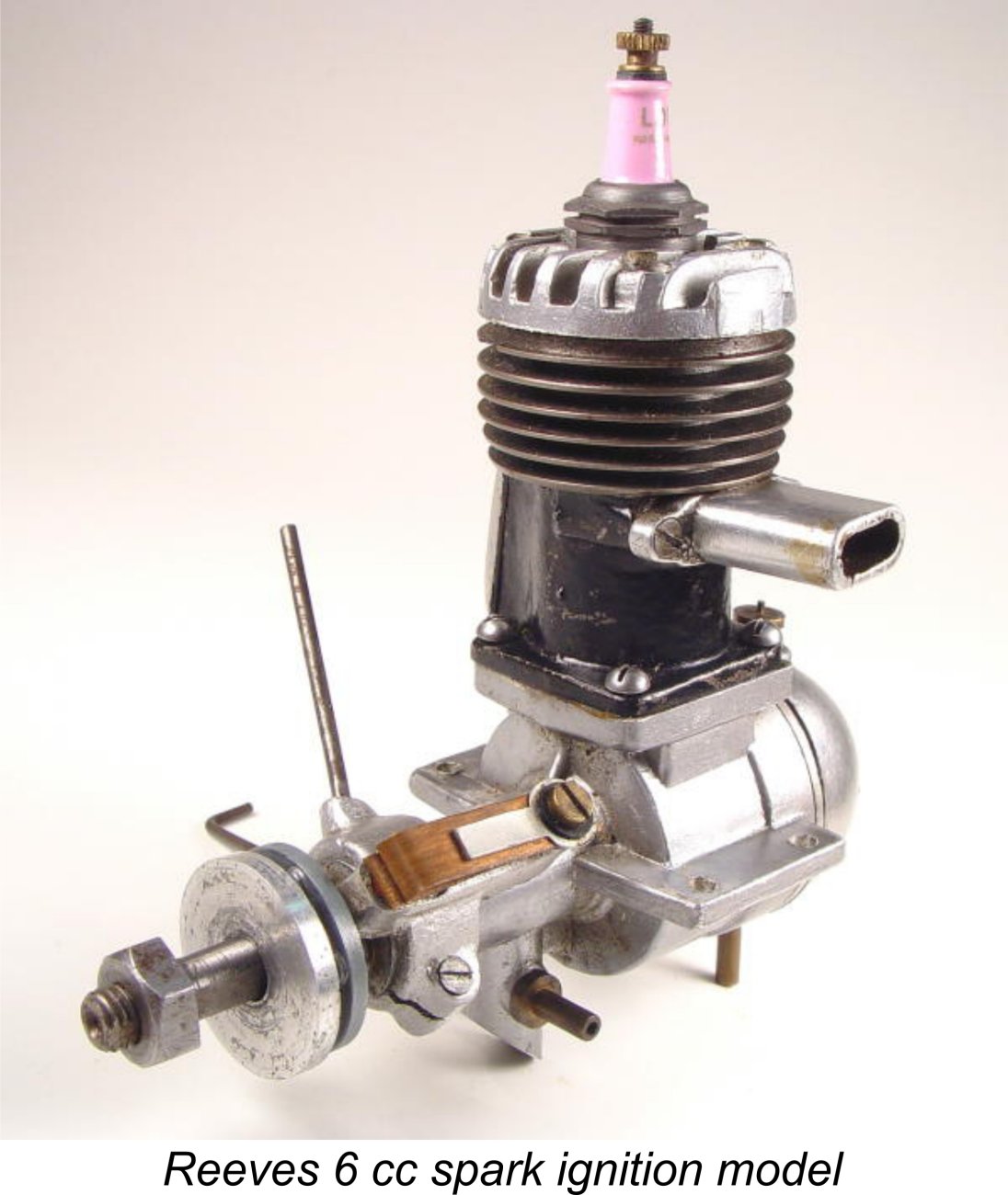 Reeves entered the commercial model engine field in mid 1946 with the first of two successive variants of a 6 cc crankshaft front rotary valve (FRV) spark ignition design. The 5 cc variant mentioned in the initial advertisements seems to have faded into the background fairly quickly, while the 10 cc model never made an appearance as far as the record shows.
 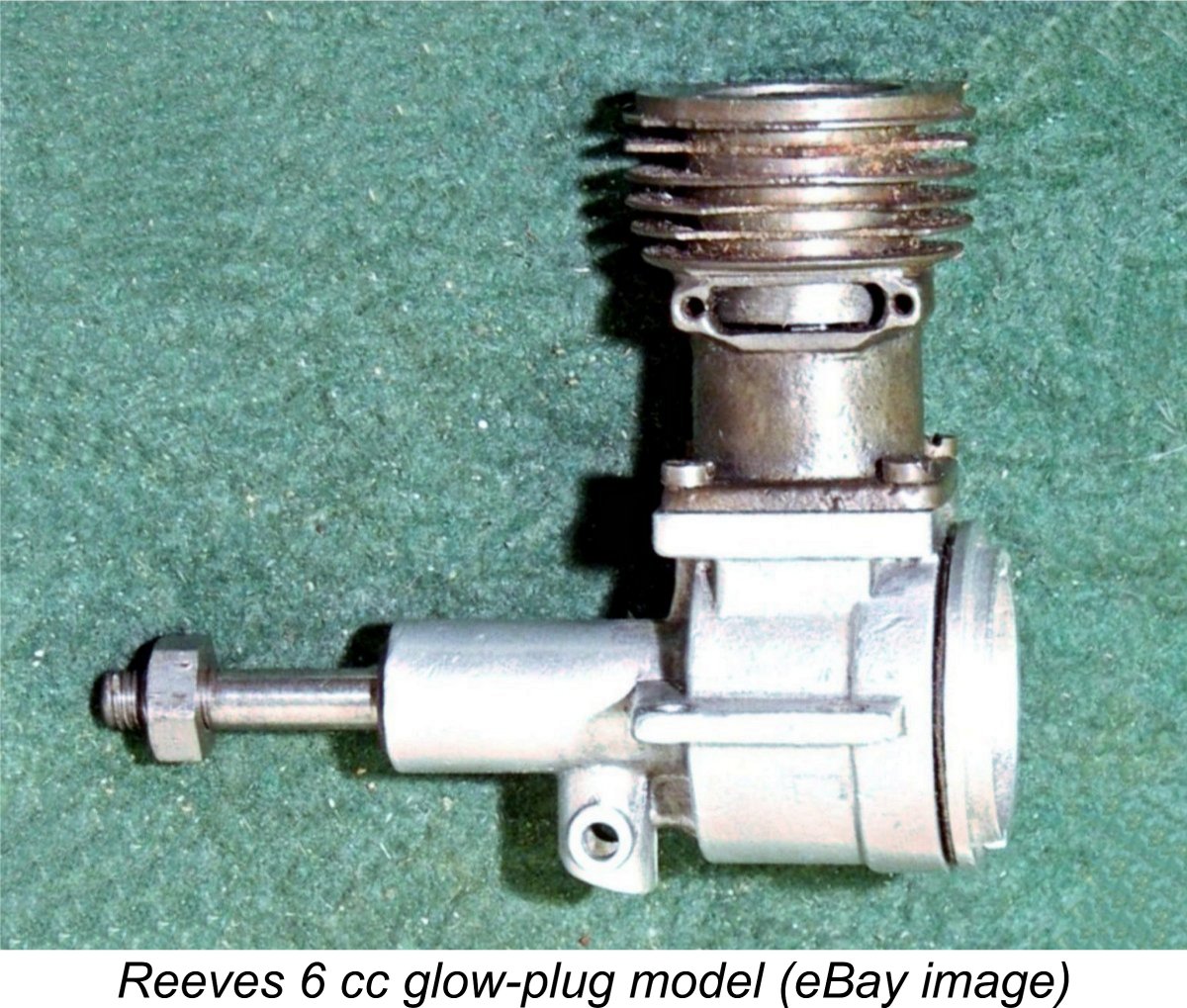 The successive variants of the Reeves 6 cc sparker enjoyed a two-year production run, selling steadily enough that the small workshop in which they were made was obviously kept quite sufficiently busy to justify continued production and further product development. As mentioned earlier, I was lucky enough to acquire two very fine and complete examples of this very competently-designed and well-made unit. The
 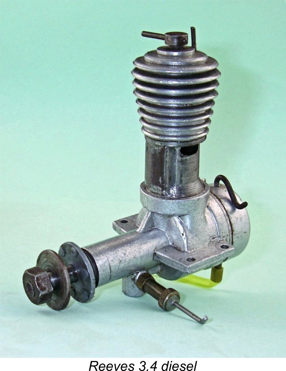 The 3.18 cc
 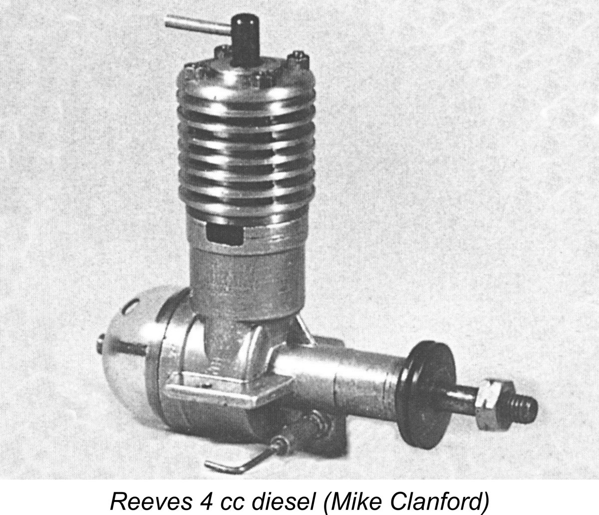 The Reeves 3.4 model was still being advertised in late 1949 - an advertisement appeared at that time in the 1949 “Aeromodeller Annual” in which the price of the engine was quoted as a quite reasonable £3 7s 6d (£3.38). This price apparently included the provision of a glow-plug conversion kit - a common practise among British manufacturers of the day. Castings were said to be available as well, and reference was made to “other engines” in the range, although exactly what these other models were was not made clear.
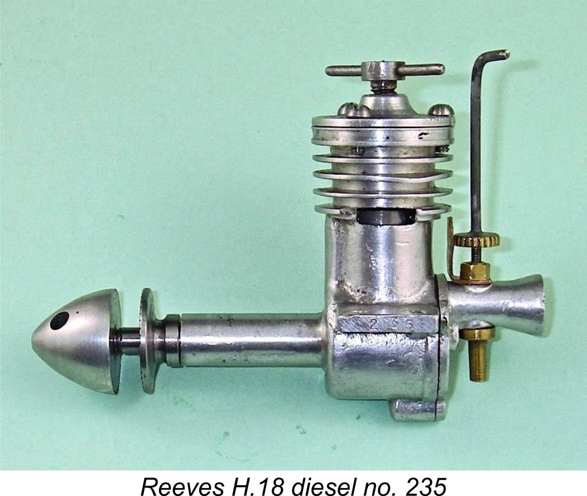
 At first glance, the Goblin gave the impression that it was simply a scaled-up and somewhat re-styled version of the earlier Reeves H.18.
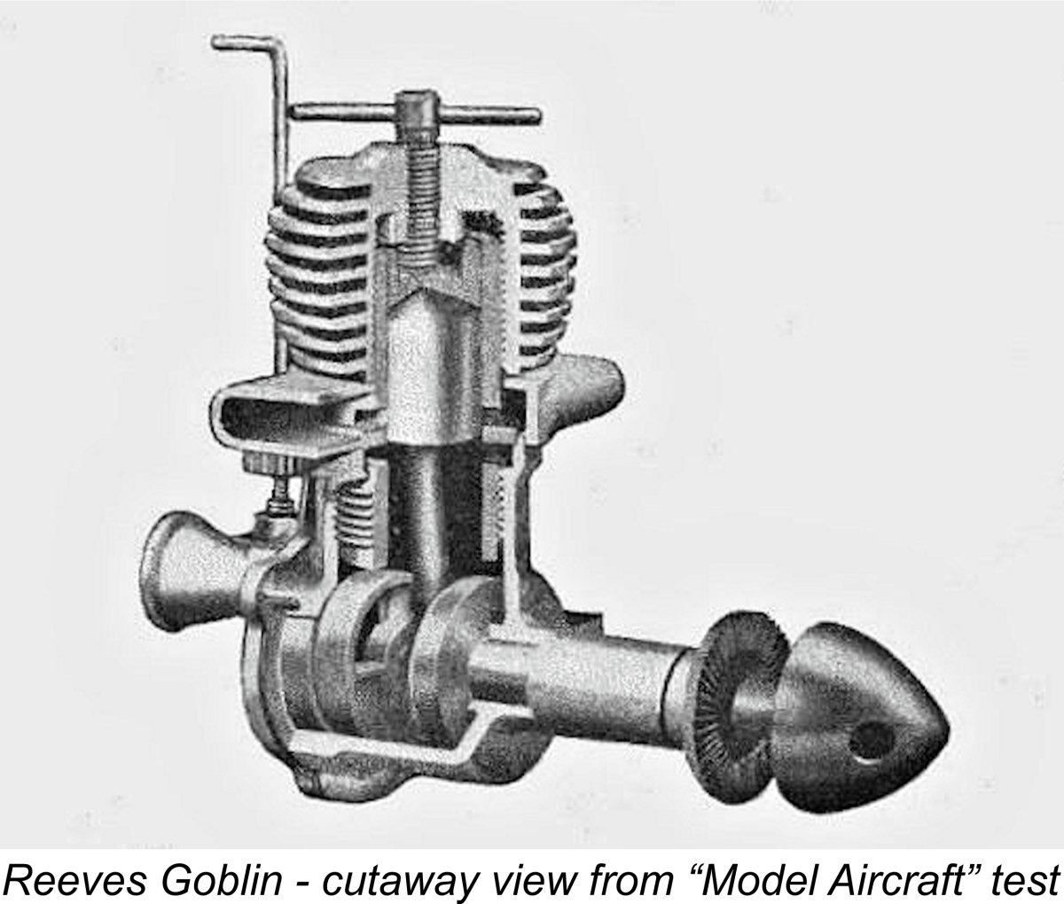
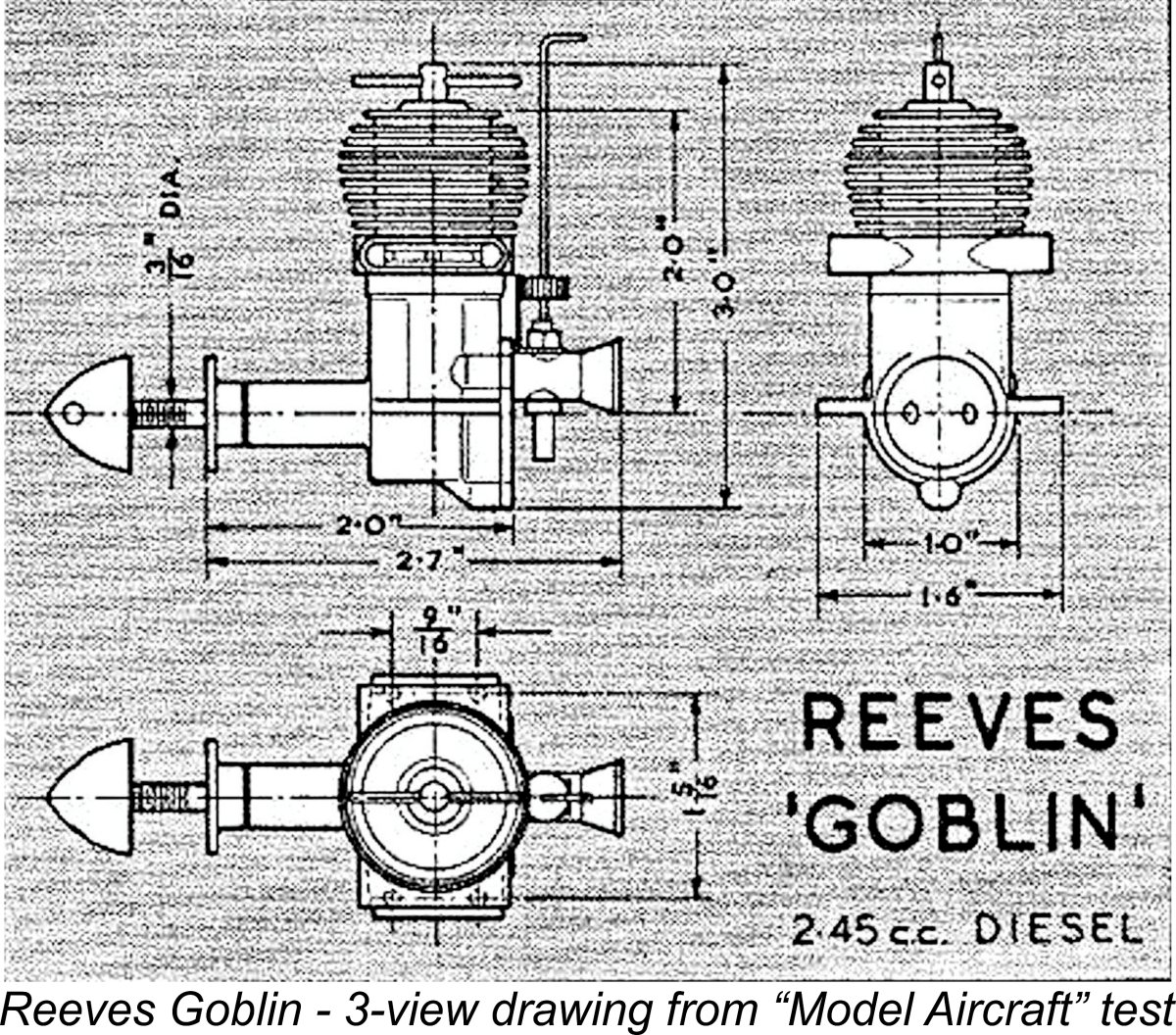 ry, the Goblin is a completely different design in functional terms when compared with the H.18. For starters, it's a long-stroke engine (unlike the short-stroke H.18), having bore and stroke measurements of 0.566 in. (14.38 mm) and 0.594 in. (15.09 mm) respectively for a displacement of 2.45 cc (0.149 cuin.). Claimed weight was a commendably light 4.1 ounces (116 gm), only 31 gm more than the smaller-displacement H.18. My own example of the Goblin actually weighs in at 4.3 ounces (122 gm).
 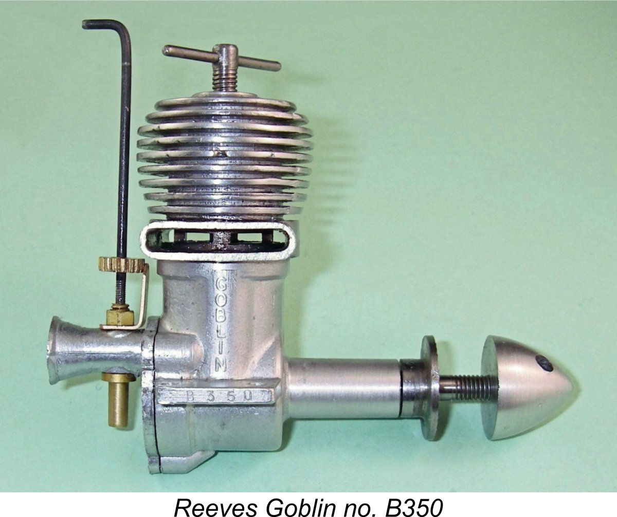 The cylinder porting of the Goblin is quite different from that of the H.18, which had two large rectangular exhaust ports, one on each side. These fed exhaust gas into two outlet ducts formed one on each side of the upper crankcase. A single transfer port was provided in the form of an upwardly-angled drilled hole located between the two exhaust ports at the front.
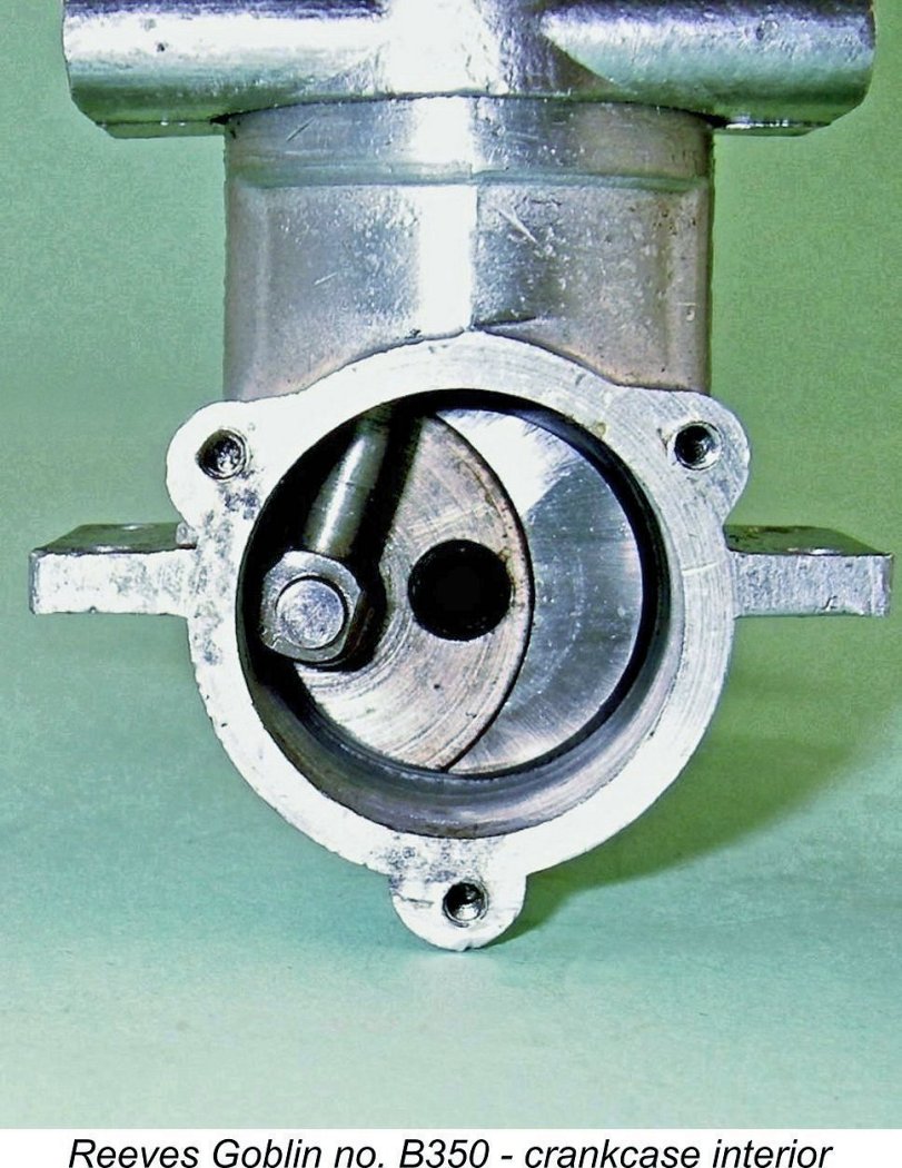 The four transfer slots are supplied with mixture by an annular cavity which completely surrounds the outer cylinder wall at transfer height. This annular passage is supplied through two vertical bypass passages of generous proportions placed one on each side, interrupting the female cylinder installation thread. Sound familiar?!? It should - it's none other than the bypass system patented in the USA by Charles Brebeck and used in his OK Cub series of model engines!
 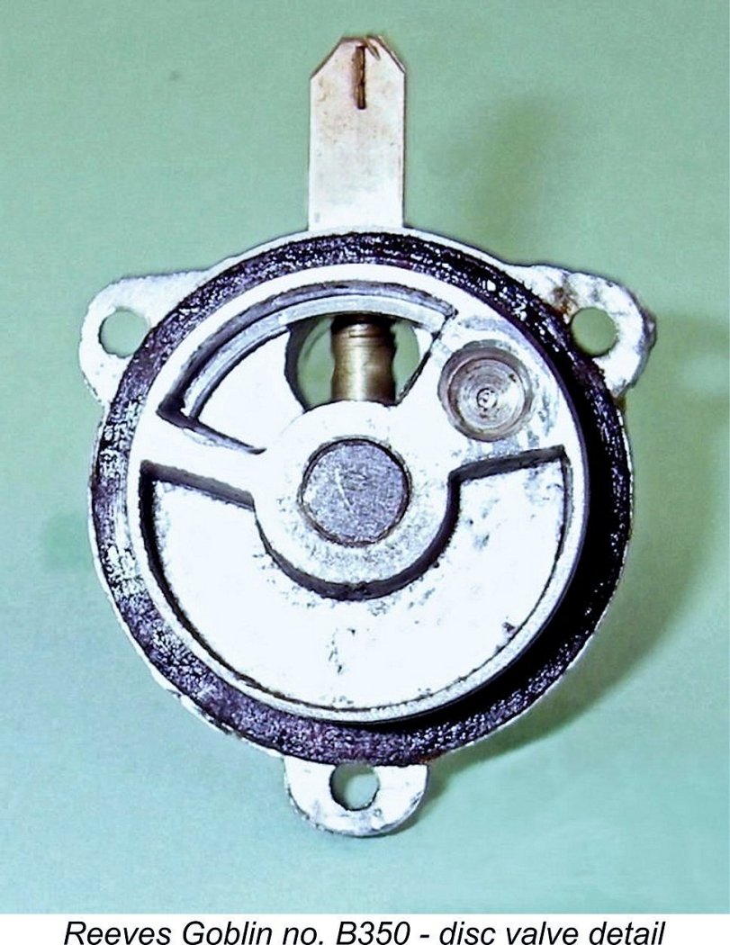 Looking now at the rear of the engine, readers of my earlier article on the
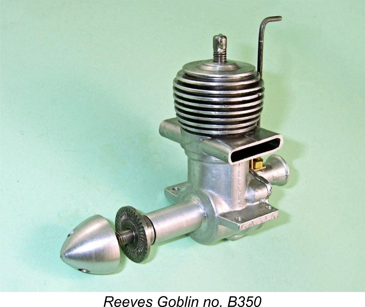
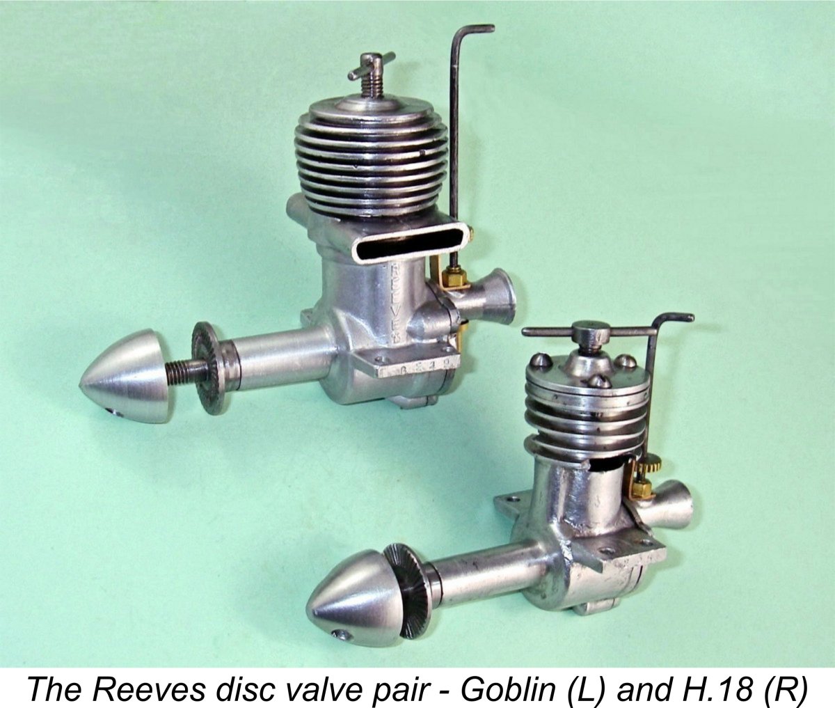
 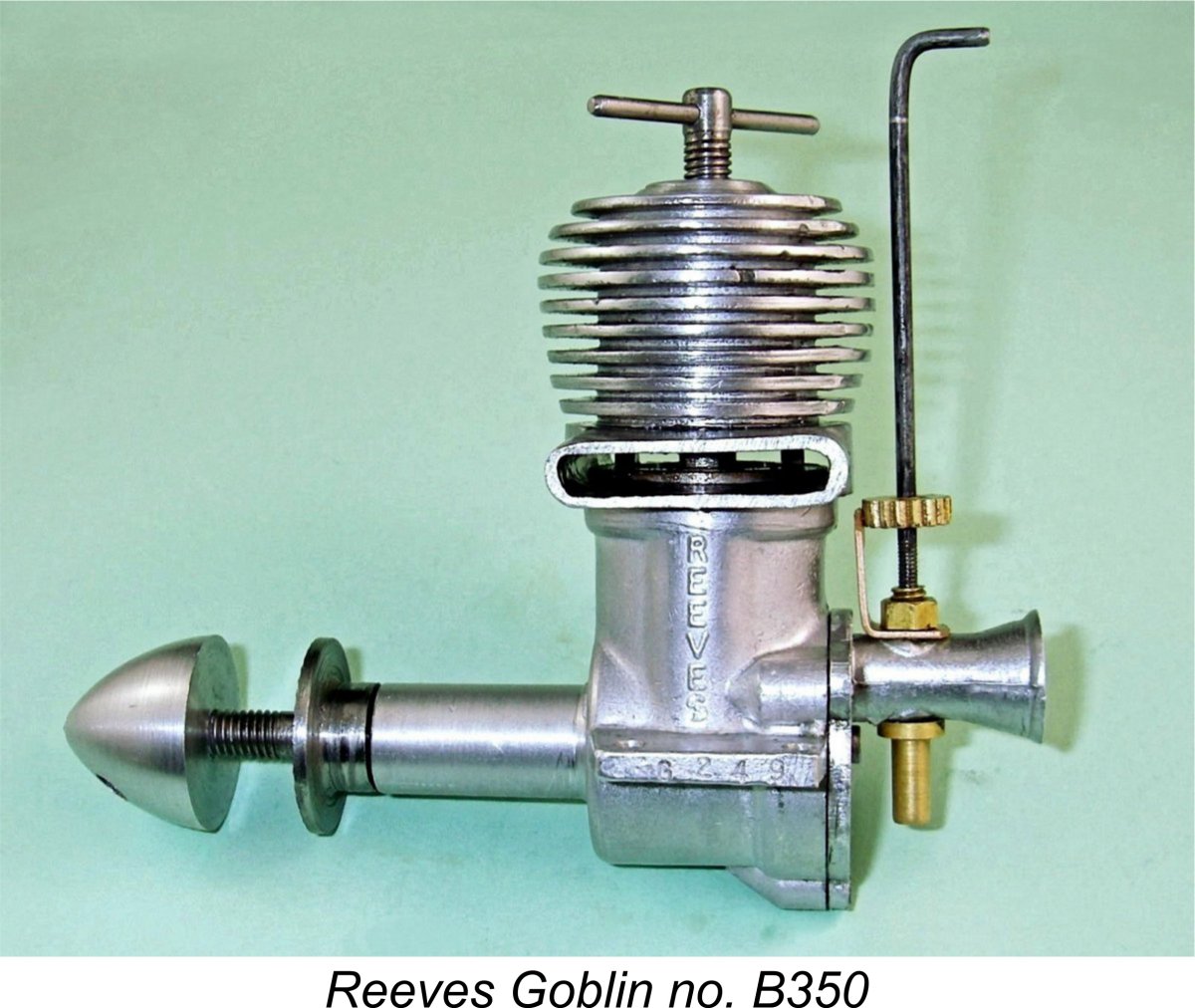 The Goblin bears a number of identifying marks. The name REEVES is cast vertically in relief onto the left-hand side of the upper crankcase (looking forward in the direction of flight), while the name GOBLIN is similarly cast in relief onto the right-hand side of the upper crankcase. The outer end of the left-hand mounting lug bears the neatly-stamped sequence G249 (presumably the manufacturer's identification code for the Goblin), while the outer end of the right-hand lug displays the stamped sequence B350. The latter is clearly this particular engine's serial number, since it is repeated on the warranty slip which is still with the engine.
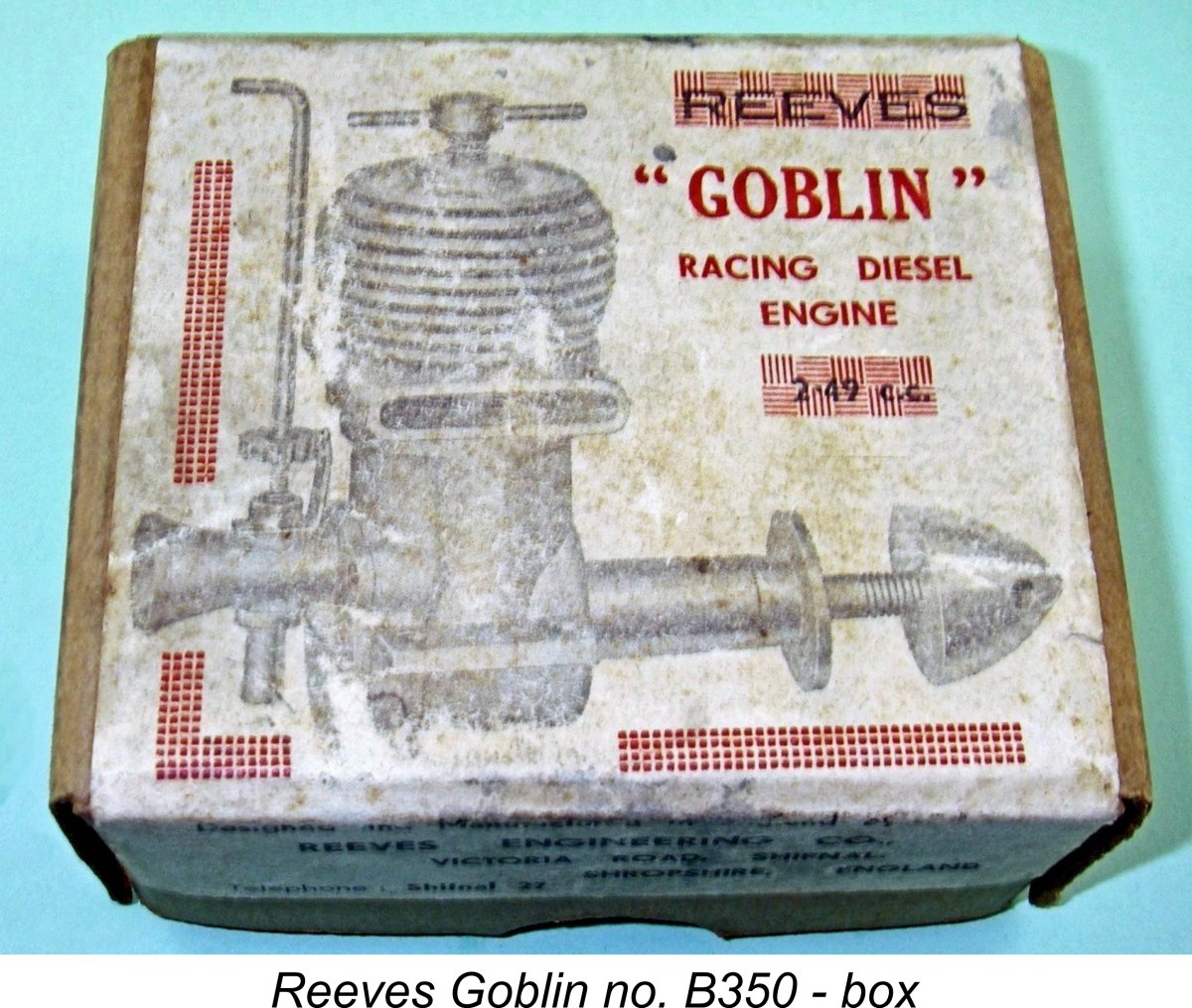
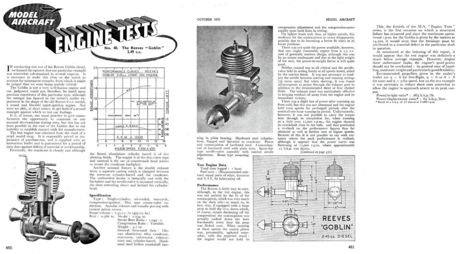 This test falls somewhat outside of Chinn’s normal approach in that it is generally negative in tone. In writing up his test reports (particularly when the subject was a British engine), Chinn tended to look for a positive spin, highlighting the favourable attributes of his test subject in comparison with any negative characteristics. In cases in which positive comments were thin on the ground, Chinn’s normal practise seems to have been to refrain from publishing any test at all, thus sidestepping the necessity of publishing a mainly negative review. This approach was likely driven by Chinn’s need to retain the trust of the model engine manufacturing community, who routinely sought his comments on their latest offerings at the prototype stage. There are a number of examples of such self-restraint being exercised by Chinn during his long and distinguished career as an engine tester.
 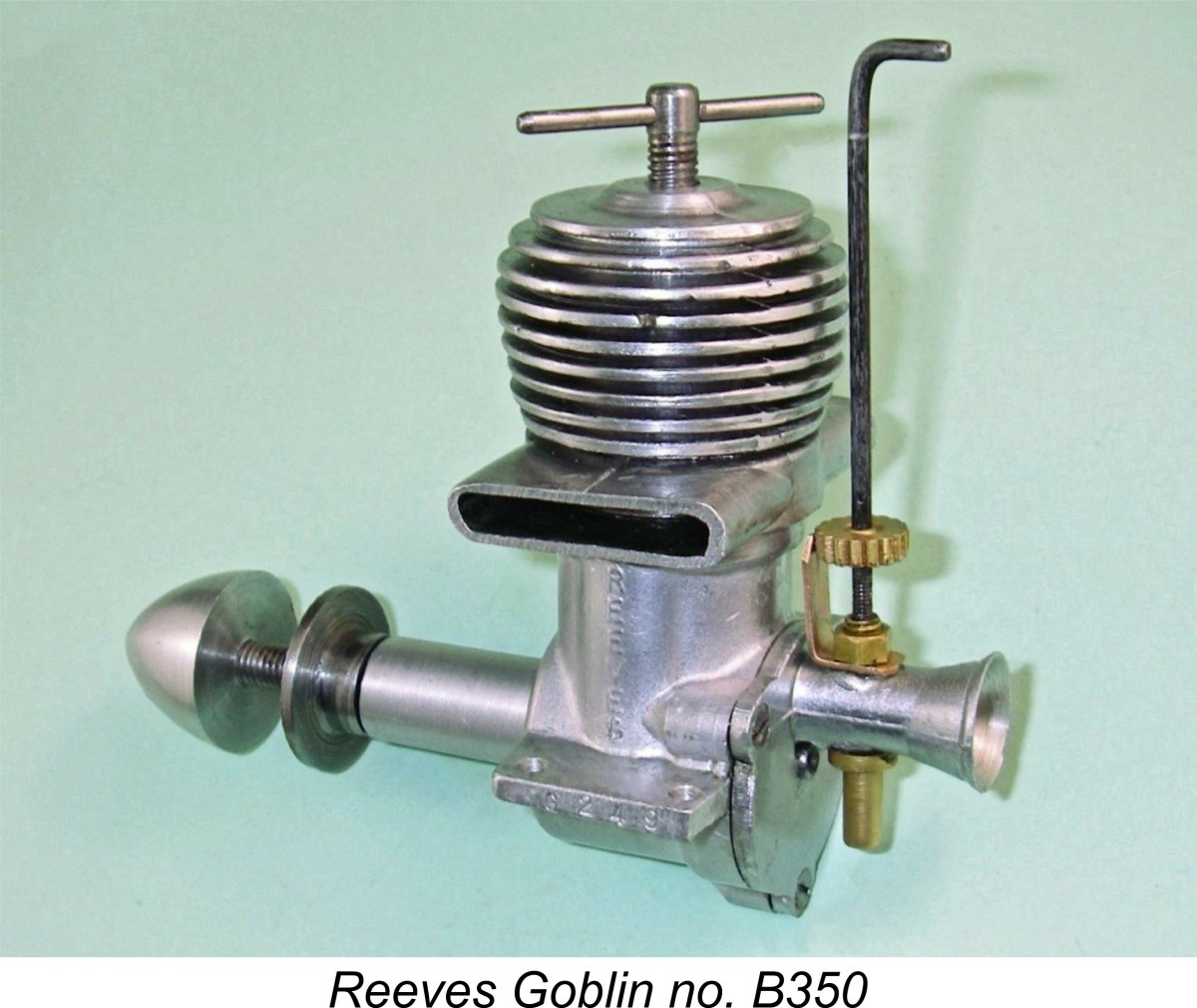 Unfortunately, the Goblin was an example of a British-made engine in connection with which Chinn found many points of criticism and did not refrain from publishing his findings. He did his best for the manufacturer by stating right at the outset that his test unit (which was obtained at random from a hobby shop) was almost certainly a sub-standard example. He also commented favorably upon the engine’s reasonable price and unusually light weight for its size. The Goblin was characterized as being “reasonably easy to start”, while the twin exhaust stacks were praised for their role in directing exhaust residues away from the engine (and model). Chinn likewise drew attention to the engine’s apparent operational flexibility.
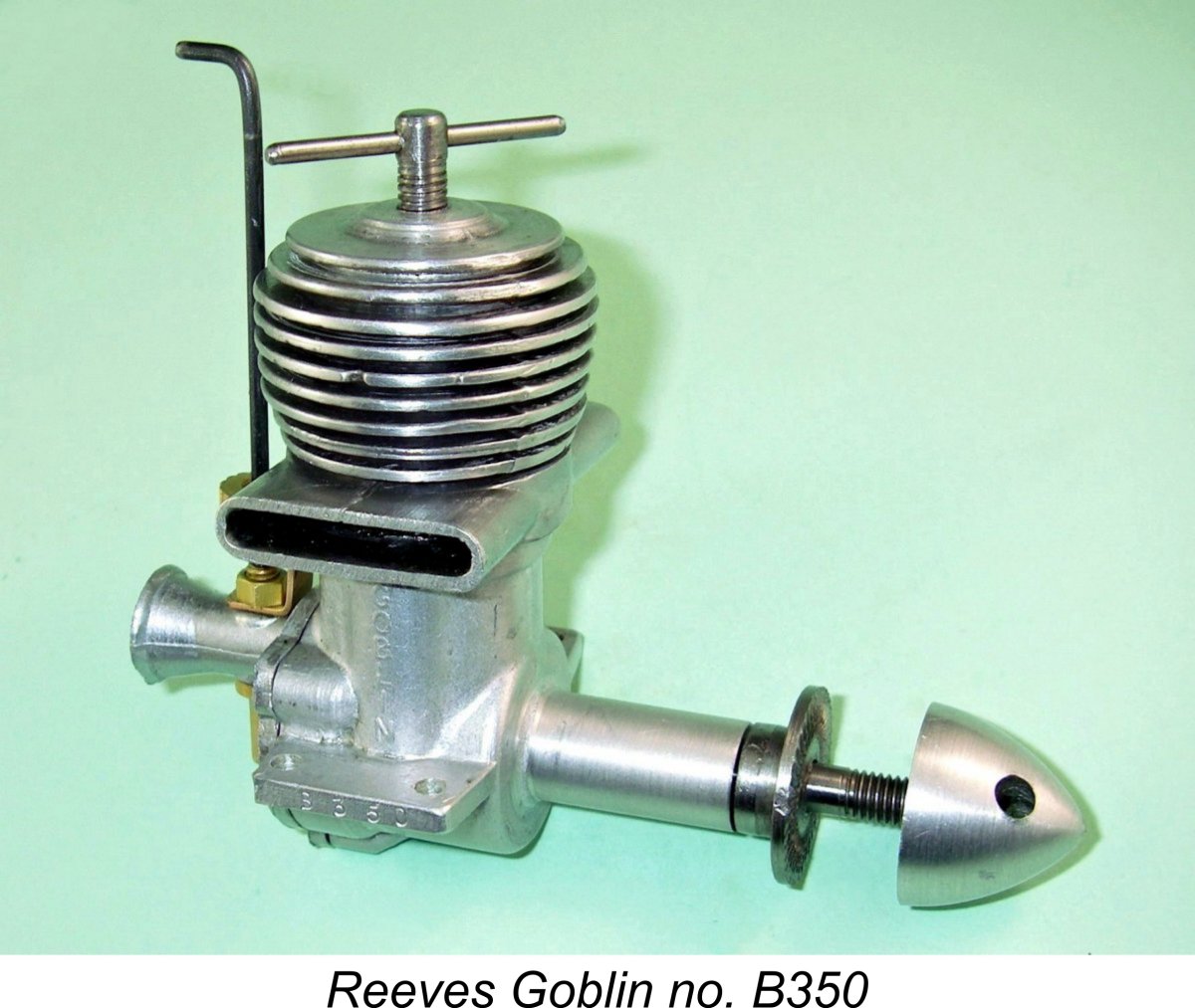 As far as performance went, Chinn stated that “there was not quite the power available …..that one might reasonably expect from a 2.5 cc engine of modern design”. Once again he did his best for the manufacturer by stating that although below expectations, the output was “by no means inadequate”. He also noted that the engine’s light weight meant that the power-to-weight ratio was “still quite good”.
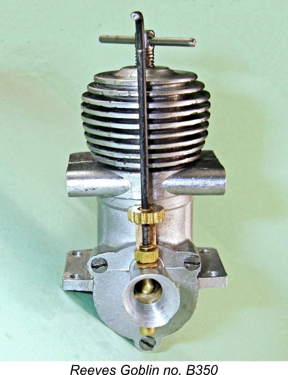 This of course represents the minimum peak output of the test engine, although Chinn also noted that the power curve appeared to be flattening out towards its peak at that point. It’s thus unlikely that his example would have delivered a significantly higher figure even if the crankshaft failure had not occurred. As noted by Chinn, the engine’s light weight of only 4.1 ounces was a point in its favour, while the implied power output of at least 0.17 BHP at 11,000 rpm was actually a quite acceptable figure for a lightweight plain-bearing 2.5 cc diesel by 1952 standards.
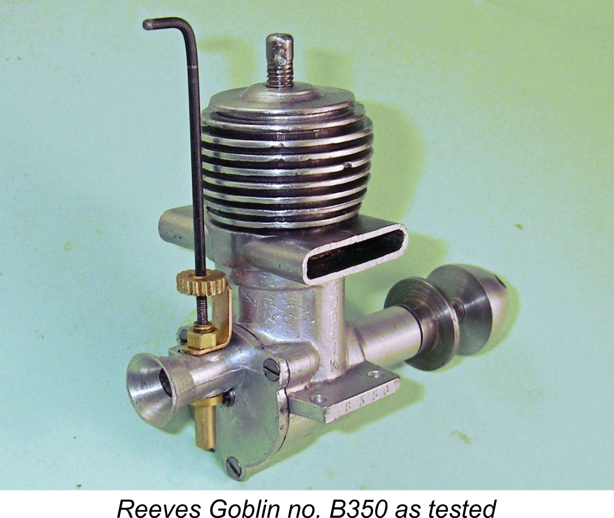 In making this decision, I was fully mindful of Peter Chinn's problem with the crankshaft as well as the very real possibility that this represented a chronic design fault rather than an isolated incident. However, part of this exercise was to determine if that incident was a "one-off" or if this was a chronic weakness with these engines. If a problem did develop, the question would be answered!
 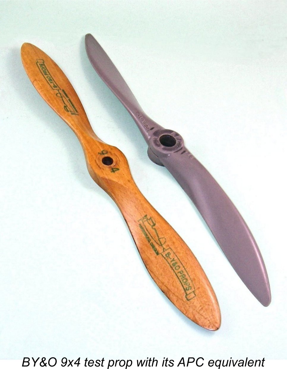 eed, a heavier prop will resist acceleration more effectively than a lighter one. As a result, it will require more torque to accelerate it, causing the momentary torque in the shaft during the power stroke to reach a higher peak. Conversely, on the compression stroke the lighter prop at the same speed will exert a lesser torque upon the shaft, albeit still sufficient to bring the piston back up to top dead centre against compression so that the cycle can be repeated.
 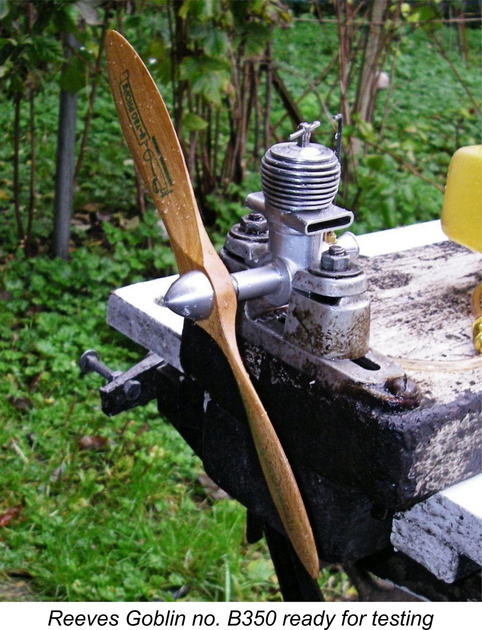 The Goblin was soon mounted in the test stand and all ready for action. I had made up some fresh fuel having a 30% oil content as well as 2½% ignition improver to maximise the engine's chance of survival by reducing compression requirements. With the BY&O 9x4 prop fitted and using this fuel, I primed the engine and got stuck in.
 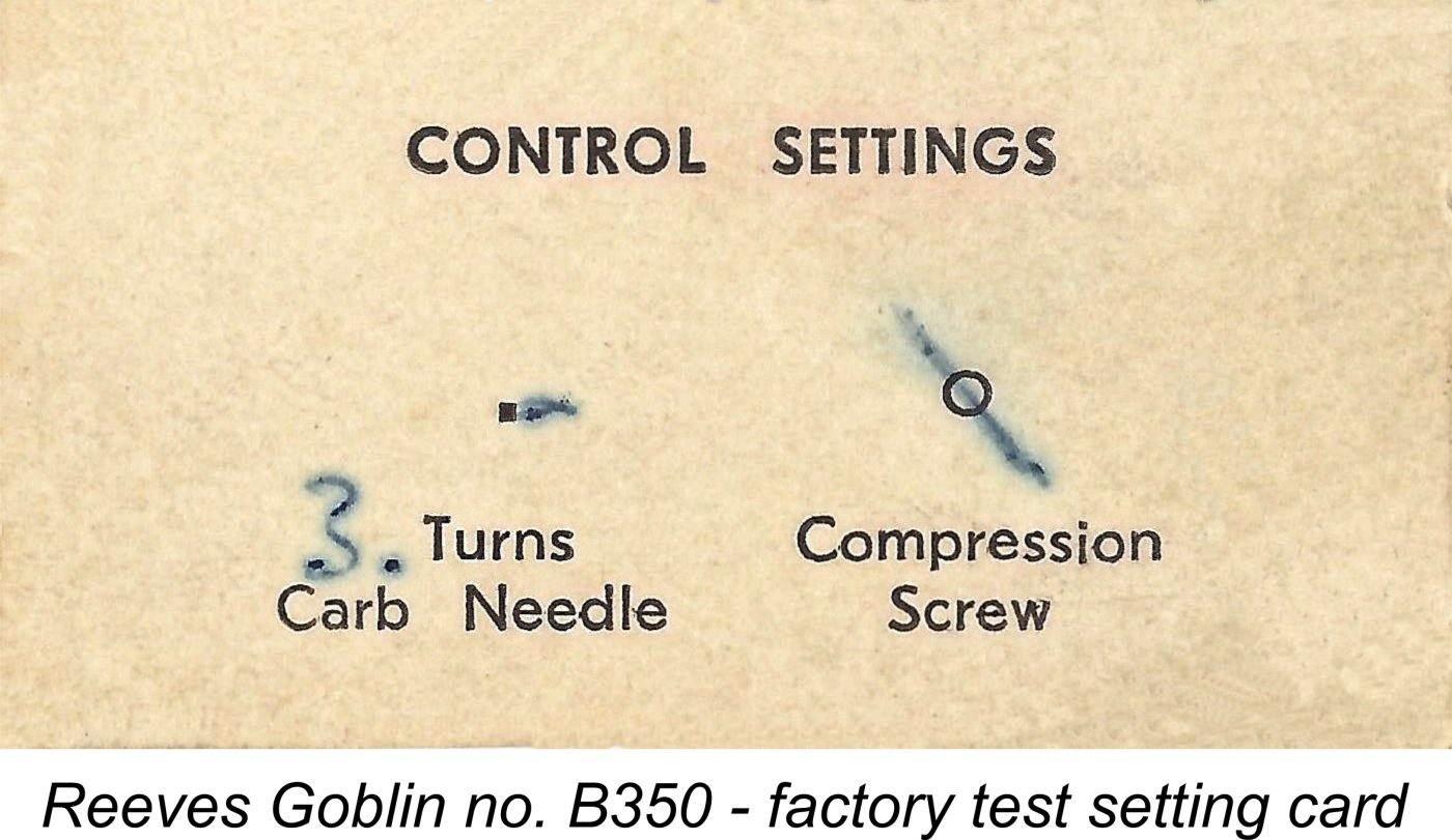 Once a compression setting was established which would generate a firing burst, the next issue was the establishment of a needle setting. I began with the needle set at three turns, as suggested on the engine's test card. However, the engine would not keep running at that setting - I had to open it out to 4½
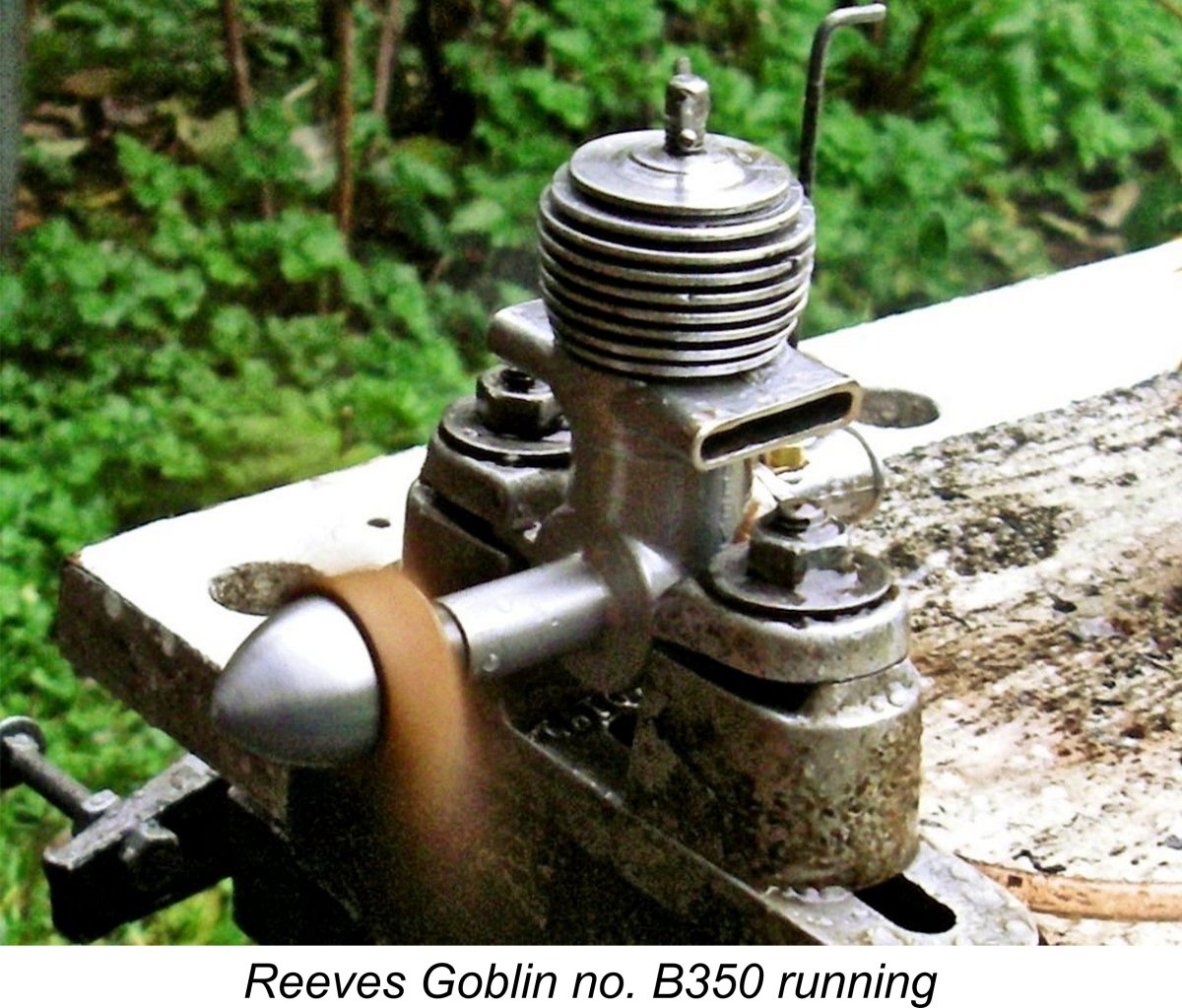 Once running, a new problem quickly became apparent. The engine burbled away quite happily when set rich and undercompressed, as it was for starting. However, when one leaned out the mixture and increased compression to smooth out the running, the engine quickly began to sound laboured, starting to sag at the same time. All the symptoms of an over-tight piston, in fact. Eventually it would labour to a halt despite all of my efforts to keep it going. Immediately after stopping, the cylinder felt extremely hot.
 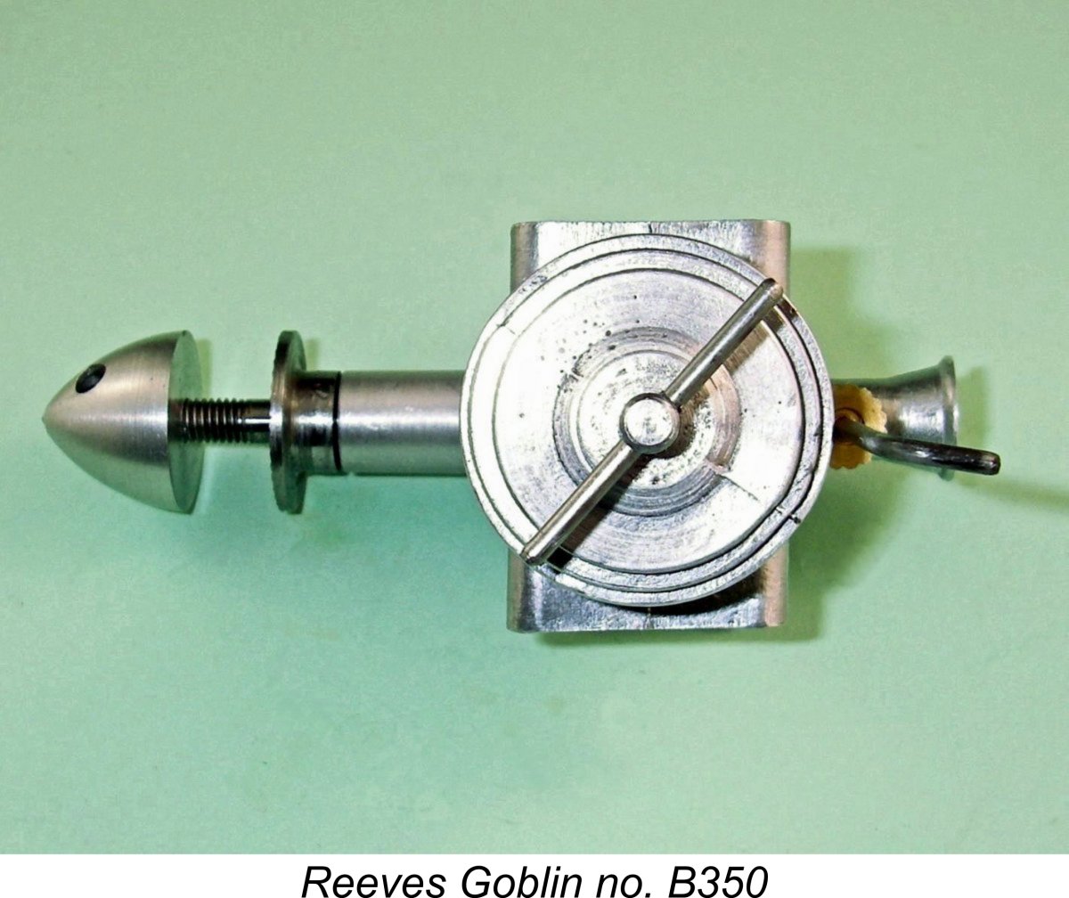 Throughout this procedure, the engine remained very easy to start from cold using the single-choke-and-prime approach noted above. I would not characterize the Goblin as a one-flick starter - it usually took a few flicks to get it going. However, I would definitely characterize it as a dependable starter, responding very consistently and requiring relatively little effort to get it going. Once running, the engine's exhaust note was notably sharp and penetrating, clearly reflecting the very early opening of its exhaust ports.
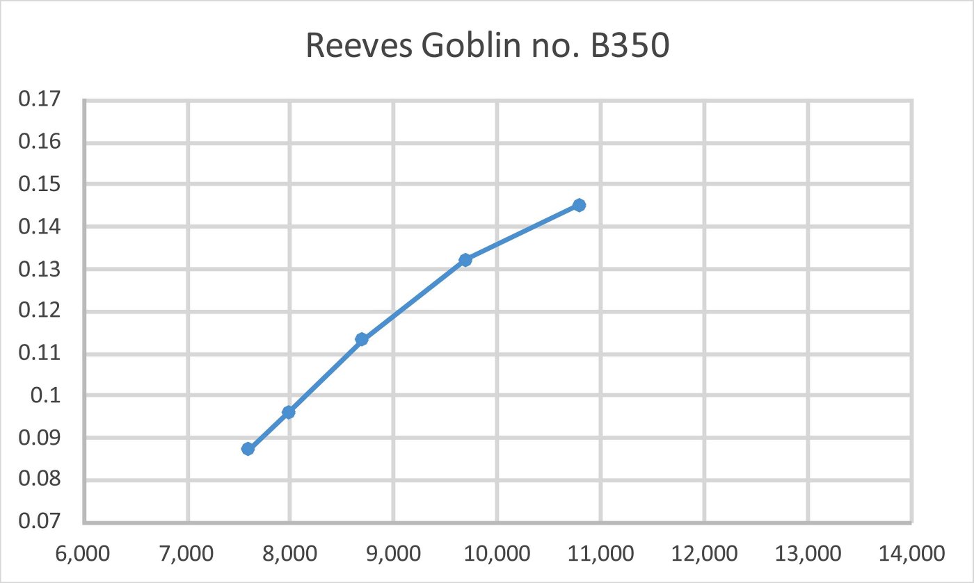
 I have to say that this was one of the most frustrating tests of my model engine career, since I was conscious all the time that the engine was by no means delivering its best. It's apparent that Peter Chinn's example ran quite a bit better than mine - presumably it had a properly-fitted piston, since Chinn made no mention of any over-heating and sagging issues. Moreover, the fact that Fisher reported having used the Goblin successfully confirms that my example may well be atypically tight.
  The test reported above had clearly demonstrated that my example of the Goblin was unuseable as it stood. I found this situation to be quite unsatisfactory, since it deprived me of any opportunity to determine just what the true potential of the design may have been. Since the engine was unuseable in any case, I felt that I had nothing to lose by taking action to correct the engine's major design deficiencies, after which a further test with hopefully more representative results could be conducted.
 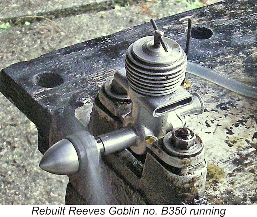 alloy conrod, leaving the rest of the engine unchanged. With the new components fitted, he
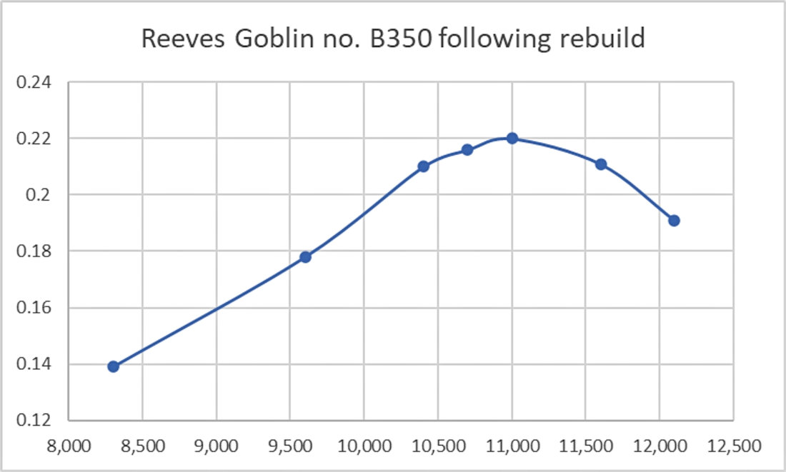
 the earlier testing of both Peter Chinn and myself. That said, it's interesting to note that the peak output was found to lie at just over 11,000 rpm, very close to the peaking speeds implied in earlier testing both by myself and Chinn. This suggests that the main result of Dean's rebuild was a significant increase in torque development rather than peaking speed.
 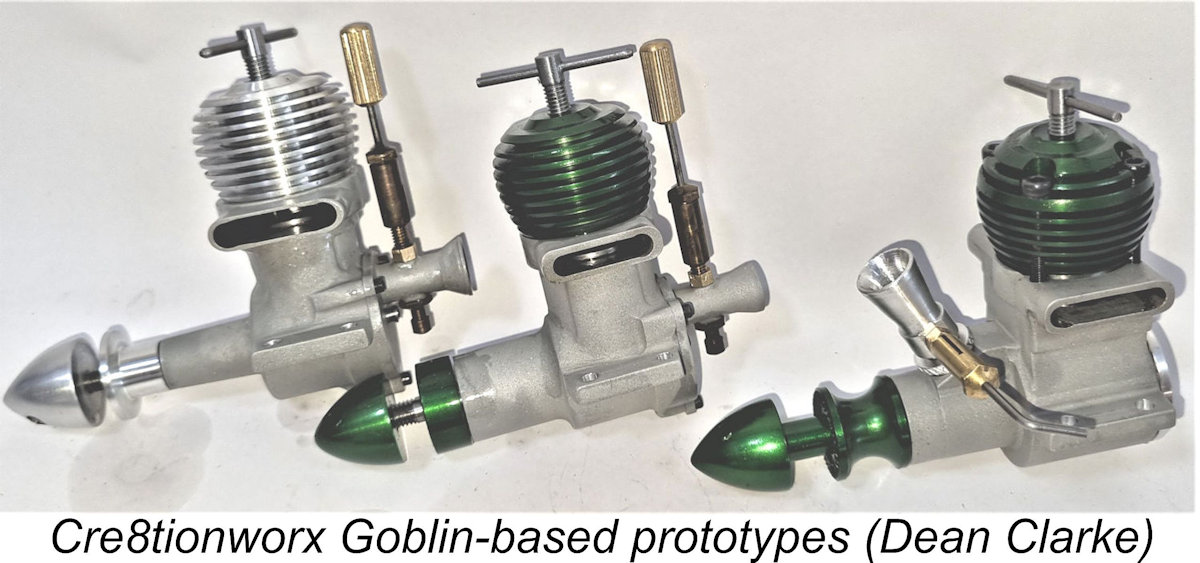 While Reeves Goblin no. B350 was in the more than capable hands of Dean Clarke for re-building, Dean took full advantage of the opportunity to finalize the design specifications for a replica of the Goblin to be produced as a limited edition by Cre8tionworx Engineering.
 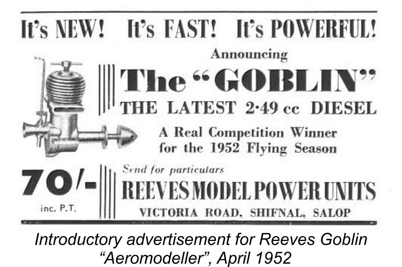 The fact that the later Reeves boxes bore the new company name is significant in my view when it comes to considering the following scenario. Reeves had gone to the trouble and expense of getting a stock of re-labelled boxes and papers made up with the new address, clearly implying that he had every intention of remaining in the model engine business at that stage, name change notwithstanding. Beginning in April 1952, he also spent money initiating a well-focused advertising campaign promoting the Goblin. The decision to abandon the field and end all communication with customers (as witness Peter Chinn's experience only a few months later) seems to have been triggered by a sudden and unexpected change in circumstances. What could these circumstances have been?
 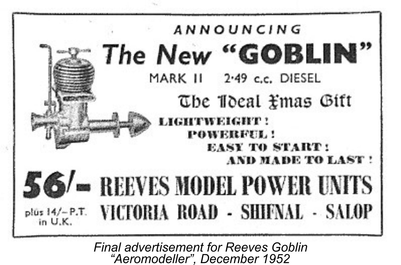 The publication of Chinn's test must surely have caused demand for the Goblin to evaporate overnight. This would have left Reeves with a considerable stock of previously-manufactured engines, which represented a significant amount of tied-up capital. It's clear that Reeves hoped against hope to liquidate this asset, because he continued to advertise sporadically for a few more months following the appearance of Chinn’s damning test. The final Reeves advertisement appeared in the December 1952 issue of “Aeromodeller”, still promoting the Goblin and still citing the company name as Reeves Model Power Units. This may be a sign that Edward Reeves was trying to maintain some distance between the Goblin and his newly re-named company.
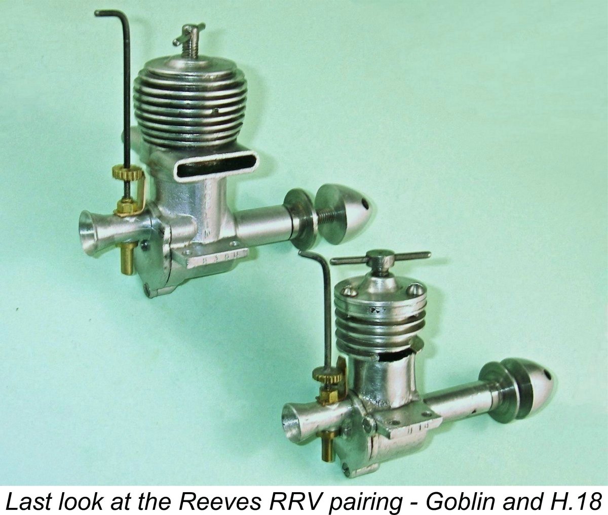 So there you have it – a summary of the sadly clouded swan-song of one of England’s more enduring but ultimately unsuccessful small-scale “artisan” model engine manufacturers. This was a range that started out with high hopes and excellent manufacturing standards, if a little behind the times in design and performance terms.
 | |