
|
|
The H-P Engines
The early post-war British H-P engines were marketed in relatively modest numbers by a firm known as Morborne Requisites Ltd. which was located in Barnet, Hertfordshire, England, a little to the north-west of London. However, the range actually had its origins in early 1946 when the initial designs were manufactured and marketed by a different firm under the Atlas name. Unfortunately, both the Atlas and H-P model engines were very sparsely documented during their period of production. As a result, documentary source information is thin on the ground. Moreover, due to their comparative present-day rarity, opportunities for examining examples at first hand are rather limited. I’ll have to do the best that I can on the basis of the somewhat scanty information that is available, including a number of images extracted from various publications or provided by my valued colleagues.
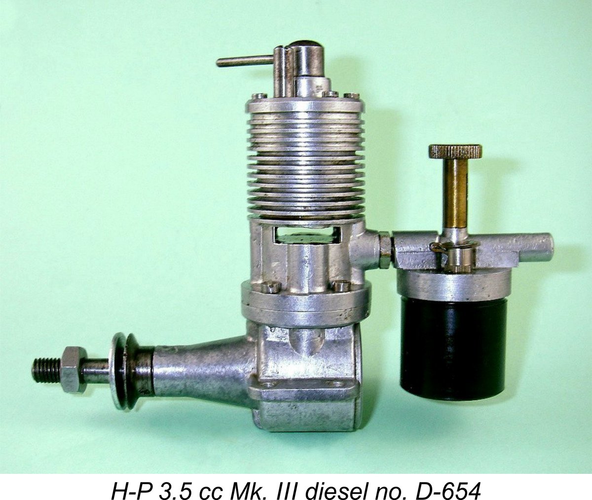
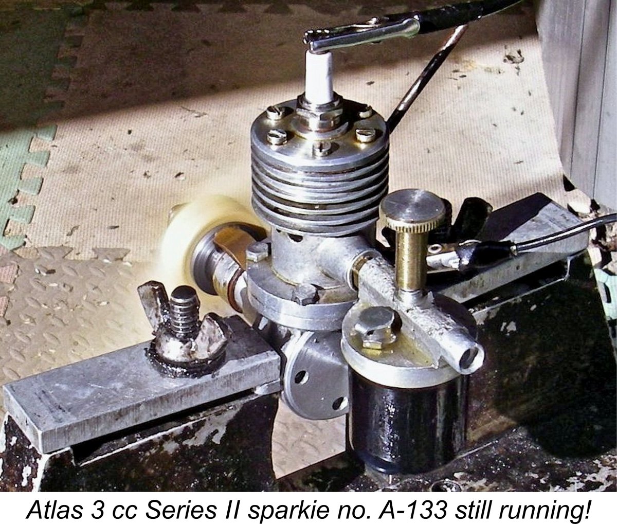
Thankfully, I do have good representative examples of both the Atlas and H.P. ranges in the form of an Atlas 3 cc Series II sparker and a Mk. III variant of the H-P 3.5 cc diesel. This provides an opportunity to evaluate the manufacturers' capabilities at first hand as well as undertake the first-ever published tests of both engines. As always when writing about any model engine range, it’s important to place the engines in their proper context. I’ll begin by attempting to do just that. Background Although large-scale commercial model engine manufacture had become very well established in the USA prior to the late 1939 onset of WW2 in Europe, the development of the industry in Britain was very much less rapid. In large part, this was due to the far smaller financially-empowered consumer base in Britain. The relatively high cost of model engines by comparison with the average Briton’s pre-war take-home pay packet initially restricted participation in power modelling to the better-heeled members of British society, some of whom were able to obtain engines from the USA.
In the interim, a number of individuals having both the required model engineering skills and equipment managed to produce their own engines on a very limited basis for their own use and that of their friends and club-mates. A number of these engines still survive today as “wotizit” units whose makers’ names are now lost to us. Many of these unattributed individually-built motors display outstanding workmanship which meets the best model engineering standards. Check out pp. 211-213 of Mike Clanford’s very useful if sometimes unreliable 1988 “Pictorial A-Z of Vintage and Classic Model Airplane Engines” to see a representative sampling of these products of talented unknown makers, such as that illustrated here.
Towards the end of the nineteen-thirties, a couple of British firms did manage to become established as somewhat larger-scale producers, most notably the Hallam company of Poole in Dorset, who produced a Also by the late 1930's, a few American engines were finding their way onto the British market. It is in this context that we first hear of Atlas Motors, who were advertising the availability of the 6 cc Baby Cyclone engine in 1939, doing so from an address in Dover, Kent. There was no indication that they were manufacturing engines themselves at this time. The onset of war in Europe on September 1st, 1939 effectively put a stop to this activity as the efforts of all of the nation’s more capable precision engineering firms became necessarily focused upon the war effort. Atlas Motors was among the many firms involved in such activities. The fact that the flying of powered model aircraft was officially banned for most of the war-time period had effectively stopped the power aeromodelling movement in its tracks anyway. Naturally, all of the engines produced up to this point had been spark ignition types – indeed, British power modellers were widely referred to as "petrol enthusiasts" or (more colloquially) “petroleers”! However, the model compression ignition engine (commonly if improperly referred to as a “diesel”, which it isn’t!) had made its commercial appearance in Switzerland during 1938 with the commercial advent of the Etha diesels. This new type of model powerplant underwent considerable development during the wartime years in those European and The end of hostilities in mid 1945 brought about a complete change. The September 1944 lifting of the wartime ban on the operation of powered model aircraft had already paved the way for a significant upswing in the popularity of power modelling. An additional factor was the greatly enhanced level of public “air mindedness” which had been fostered by the major role played by the Royal Air Force and its allied Air Forces in winning the war. Aeromodelling was on a roll! Consequently, a considerable pent-up demand for model engines in Britain quickly became apparent. This was doubtless driven in large part by a completely understandable post-war desire to return to normalcy by resuming peace-time hobbies as quickly as possible. In addition, the novelty appeal of model engines during those early post-war years remained just as great as it had been during the pre-war period. Although the cost of such engines remained highly significant in the context of the cash-starved British post-war economy, their novelty value encouraged people to save up and buy them anyway. Engines were in relatively short supply at the time, so any motor that would start dependably, run reasonably well most of the time and keep on doing so for a while was pretty much assured of a buyer. In response to this demand, a number of new large-scale model engine manufacturing ventures quickly got off the ground, notably International Model Aircraft (IMA) with their FROG “bicycle spoke” model engine range, Mills Brothers with their original Mills 1.3 cc model and E.D. with their 2 cc sideport designs. I’ve covered the early post-war products of all three of those companies in separate articles. The long-established Hallam and Rogers & Geary firms both resumed model engine production in addition. However, the field was by no means left entirely to the large-volume manufacturers. The end of the war had left a significant number of technically-skilled military and civilian personnel looking for fresh outlets for their talents. Those among them who were interested in model engines couldn’t all go to work for the relatively few major producers. Accordingly, a handful of them went into the model engine manufacturing business on their own account. The result was the emergence in early post-war Britain of a surprising number of small-scale “cottage industry” model engine manufacturers, some of them working quite literally in the proverbial garden shed (or cow-shed in the case of the makers of the Clan engines from Fife in Scotland!). The names of Healy, M.E.C., Ace, E.P.C., B.M.P., Wilsco, Dyne, Comet, G.H.G., Rawlings, Gerald Smith, Leesil, Owat, Masco (castings only), E.R.E., Milford, M.S. of Newcastle-upon-Tyne, the Model Aerodrome of Birmingham with their infamous Drome Demon and Seymour, Hylda & Co. (Foursome and Kalper) spring immediately to mind, and there were others. Indeed, there were almost certainly a number of such small-scale “artisan” ventures whose names are now lost to us.
Another such mid-scale firm was the Atlas Motors company which we first encoutered back in 1939 offering the Baby Cyclone engine from America. As of January 1946 the firm had relocated from its pre-war location at Dover to Studham, near Dunstable in Bedfordshire and was making coils for model aero engines. Interestingly enough, at this time the Atlas company was one of a number of small precision engineering firms owned by none other than D. A. Russell of “Aeromodeller” magazine fame. It has been credibly suggested that Russell’s good friend and close collaborator Lawrence H. Sparey may have had some involvement in the development of the Atlas model engines which began to appear in February 1946. More of this below in its place. Although by 1946 the model diesel was already well-known in British modelling circles, having reached a stage of development in Europe at which it was well able to compete with its spark ignition counterparts, many early post-war British manufacturers stayed with the tried-and-tested spark ignition format with which th This being the case, it's scarcely surprising that many early post-war British manufacturers and modellers alike returned initially to the spark ignition engines with which they had become familiar prior to the onset of hostilities. A perfectly rational approach - start out with what you know and develop more technologically-advanced designs as you go. E.D. and Mills were the most prominent exceptions to this, along with a very few others.
As far as can be ascertained at this point in time, the Atlas range seems to have got its start in late 1945, beginning with the appearance of a few examples of a pre-production spark ignition model which was cited as having a displacement of 3.5 cc. Examples of this engine were both on display and on sale at the Model Aircraft Exhibition at Dorland Hall in London which opened on December 14th, 1945. The advertised HIC 4 coil was also featured. Oddly enough, Mike Clanford reported the displacement of this early model as being 4 cc - who was right? Regardless of its actual displacement, this prototype featured a blind-bored steel cylinder having integrally-machined cooling fins. The first advertisement for this engine appeared in the February 1946 issue of "Aeromodeller", the displacement being given as 3.5 cc. This advertisement is reproduced at the right. This advertisement raises the first of many questions relating to the actual displacements of the Atlas and later H-P engines.The bore and stroke figures given in the advertisement yield a calculated displacement of only 2.54 cc! Even if we assume that the figures were somehow switched during the layout process for the advertisement, the displacement still works out at only 2.83 cc! So where does the claimed 3.5 cc come from? The issue of displacements will continue to bedevil us as we proceed to trace the history of the Atlas and H-P ranges.
The advertisement which is reproduced here at the left appeared in the June 1946 issue of "Aeromodeller". It's interesting to note that the engine was advertised as the "Atlas 5 cc diesel engine" despite the fact that it was unquestionably the Sparey 5 cc model in reality. This was to be the only diesel model to which the Atlas name was applied. Although a number of spark ignition accessories are included in this June 1946 advertisement, there's no mention of any Atlas spark ignition model engine. This seems to confirm that although the previously-mentioned prototype sparkie had unquestionably been advertised previously, it was not available in commercial quantities as of late March 1946, when the advertisement must have been submitted to meet the magazine's editorial deadline for the June issue.
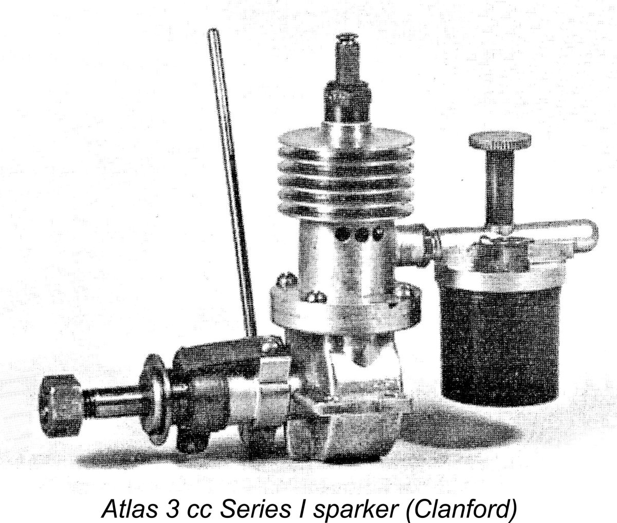
Following a further period of testing and assessment, the Atlas spark ignition prototype was further developed into a nominally 3 cc spark ignition model which made its appearance in series production form in mid 1946, certainly by September of that year. This initial production variant is generally referred to as the Atlas Series I model. It was offered in both kit and ready-to-run forms, as reflected in the accompanying advertisement from the October 1946 issue of "Aeromodeller". Sales were direct from manufacturer to customer. Note that the 5 cc diesel kit was no longer mentioned. The engine was specifically advertised as being of a nominal 3 cc displacement. This contradicts the 3.5 cc figure which has generally been assigned by previous commentators. The price of the kit was £2 2s 0d (£2.10). The complete engine ready to run was available at a price of £7 10s 0d (£7.50). Although the advertising continued to feature a photograph of the prototype engine, in reality the new spark ignition model featured a cast alloy cylinder jacket in place of the integrally-machined cooling fins and blind bore of the prototype. This cylinder jacket incorporated the cylinder head in unit as well as the bypass passage, which was placed on the right-hand side of the upper cylinder unit (looking forward in the direction of flight). The complete upper cylinder unit was located on an installation flange formed at the top of the lower crankcase casting, being secured using four machine screws.
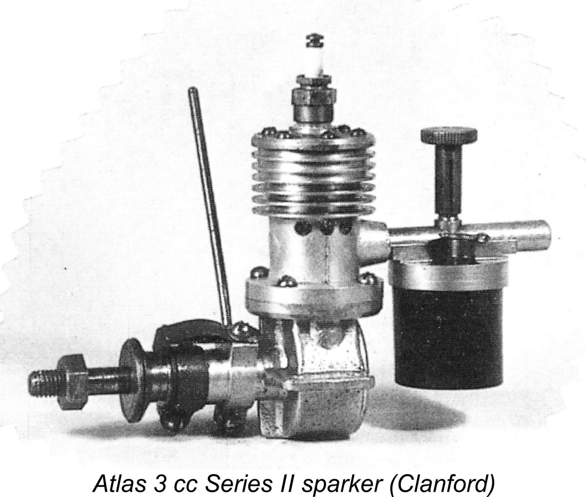
The Atlas engines seem to have quickly acquired a positive reputation among those who were able to obtain and use them. Surviving examples show the factory models to have been very well-made. Sales were evidently sufficiently encouraging that development continued, leading to the late 1946 appearance of the Atlas 3 cc Series II variant. Evidently the original Series I model did not remain long in production, hence its present-day rarity. The revised offering dispensed with the rather tricky cylinder assembly of its predecessor by employing a separate cylinder head which was attached using machine screws. In other respects, it was seemingly little changed from its predecessor. Attentive readers will have noticed that I've consistently referred to the production Atlas sparkers as having a nominal displacement of 3 cc. This contradicts most previous commentators, who have generally assigned a displacement of 3.5 cc to these engines. As it happens, I have a very solid basis for assigning that 3 cc displacement!
Interestingly enough, these are the precise figures cited in that original February 1946 Atlas advertisement but with the bore and stroke figures reversed! I suspect that the error was introduced during the layout process for that advertisement. The actual calculated displacement of 2.83 cc is completely consistent with the previously-reproduced advertisement for the Atlas Series I model, which cited a slightly exaggerated nominal displacement of 3 cc for the engine - a not uncommon upward rounding-off process. For some reason, this advertisement does not appear to have influenced the statements of earlier writers. It's a lesson to us all - before citing a displacement, check all available documentation and take measurements!! It's quite possible that other examples did have displacements higher than 3 cc, but at present we have no actual measurements to confirm this. Any volunteers?!? For now, I'm content to go with my own measurements plus the nominal displacement cited in the late 1946 advertisements. The measured compression ratio of my example is a rather meagre 5.5 to 1. In all honesty, I wouldn't give much for this engine's chances of running on glow-plug ignition or even spark ignition using methanol! The low compression ratio is probably due as much as anything to the need to accommodate a rather tall baffle on the transfer side of the piston crown.
A video of one of these engines running may be found here. Pity about the electric starter - we learn nothing about the engine's handling qualities ............ The Atlas 3 cc Series II models all appear to have carried serial numbers. These consist of the letter "A" (presumably for Atlas) stamped on one mounting lug, with the actual serial number stamped on the other lug. The backplates of these models are unmarked. These observations are extremely important in readily distinguishing the Atlas 3 cc Series II model from its very similar H-P 3.5 cc Mk. I successor. My own illustrated example of the Atlas 3 cc Series II model bears the number A-133. To sum up, we've seen that the Atlas Series I model was introduced in mid 1946, probably around July or August of that year. It was replaced later in the same year (certainly after October 1946) by the revised Atlas Series II variant. Both models appear to have had nominal displacements of 3 cc, just as advertised. The Series II model proved to be the final unit to be released under the Atlas name. Like its Series I predecessor, it seems to have had a relatively short production life, once again explaining the relative rarity of that model also. The Atlas 3 cc Series II Sparker on Test My illustrated example of the Atlas 3 cc Series II spark ignition model, engine number A-133, is in superb original condition throughout. It has been mounted and run, but appears to have had little use. Compression seal is excellent, while all bearings remain commendably free from play.
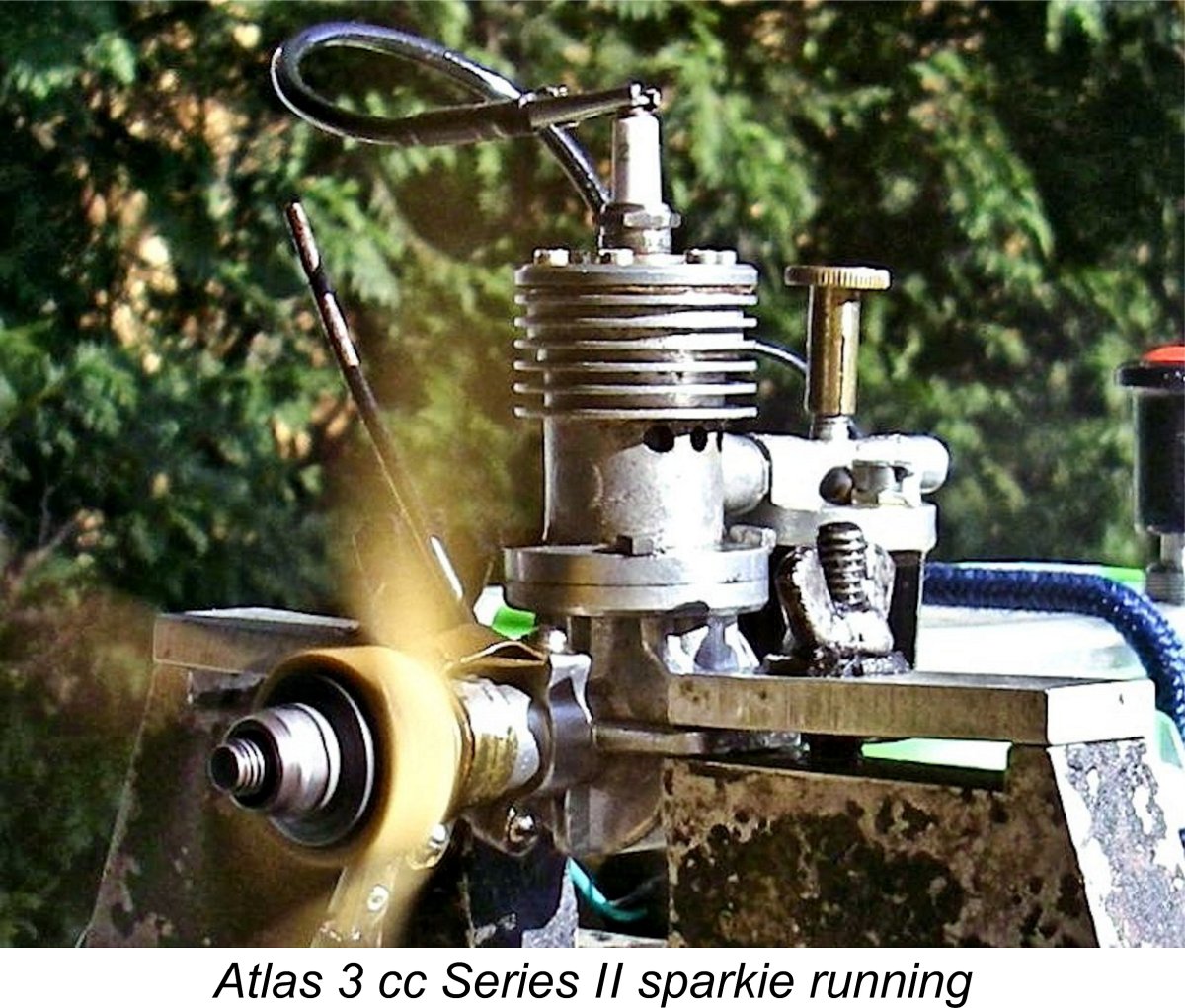
In view of the fact that this design dates from 1946, I wasn't expecting anything approaching a stellar performance. That said, the engine was clearly very well made and showed no evidence of any problems which might prevent it from running well. I ran the usual checks on the timer, finding that it functioned perfectly. The AC spark plug with which the engine was supplied was also found to be in excellent condition, allowing me to use that plug for all of my testing. I used my usual classic spark ignition fuel consisting of 3 parts Coleman camp fuel (white gas) to one part of AeroShell 120 SAE 60 mineral oil. For the initial start I fitted an 11x4 Zinger wood prop, which turned out to be a very good choice. I installed the Atlas in the test stand and hooked it up to one of my Larry Davidson spark ignition support systems. For those wishing to have a go themselves (highly recommended - it's great fun!), I've described the very straightforward construction of one of these systems in a separate article on spark ignition engine operation. After guessing the needle setting and filling the tank, I gave the Atlas a couple of choked flicks and then switched on the ignition before getting serious about going for a start. The engine began firing immediately but wouldn't keep going, seemingly flooding to a halt. As is so often the case with these old sparkers, I had clearly guessed wrong on the needle setting, in the rich direction as usual. It never fails to amaze me how little fuel is required to run one of these sparkies on white gas! I began with a setting of two turns open, but had to close down to only one turn before the engine finally started and kept going, still slightly rich.
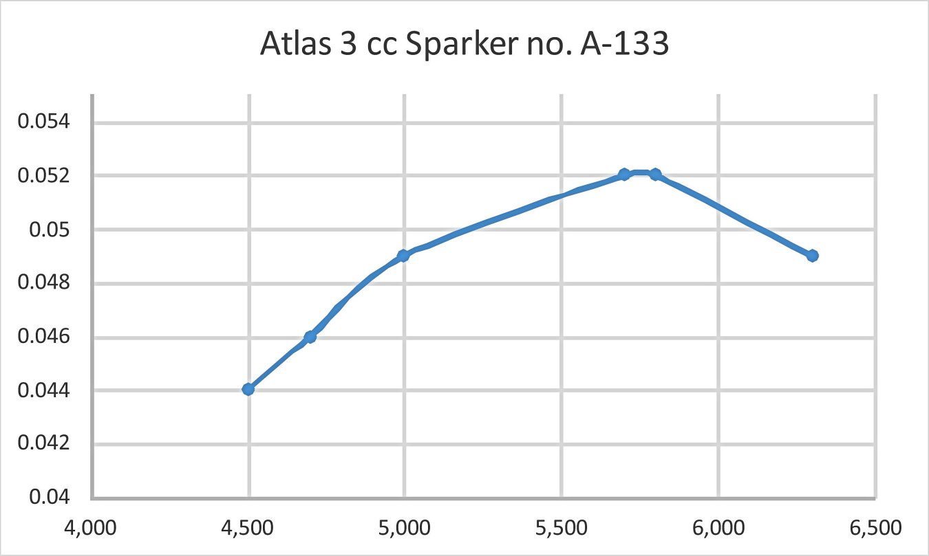
Running qualities were all that could be desired. The Atlas ran absolutely smoothly without missing a beat and with no tendency to sag. The timer clearly worked perfectly at all speeds tested. The engine seemingly ran forever on a tank - I invariably stopped it for prop changes using the ignition kill switch rather than waiting out the tank. Fuel consumption was clearly minimal. Vibration levels too were impressively low. All in all, this engine showed itself to be a very user-friendly and fine-running powerplant. That's the good news! The less positive finding was that the engine's power output was very much on the low side. The following data were obtained on test. All props were of the wooden variety - call me weird if you like, but somehow I just prefer testing sparkies using wooden props!
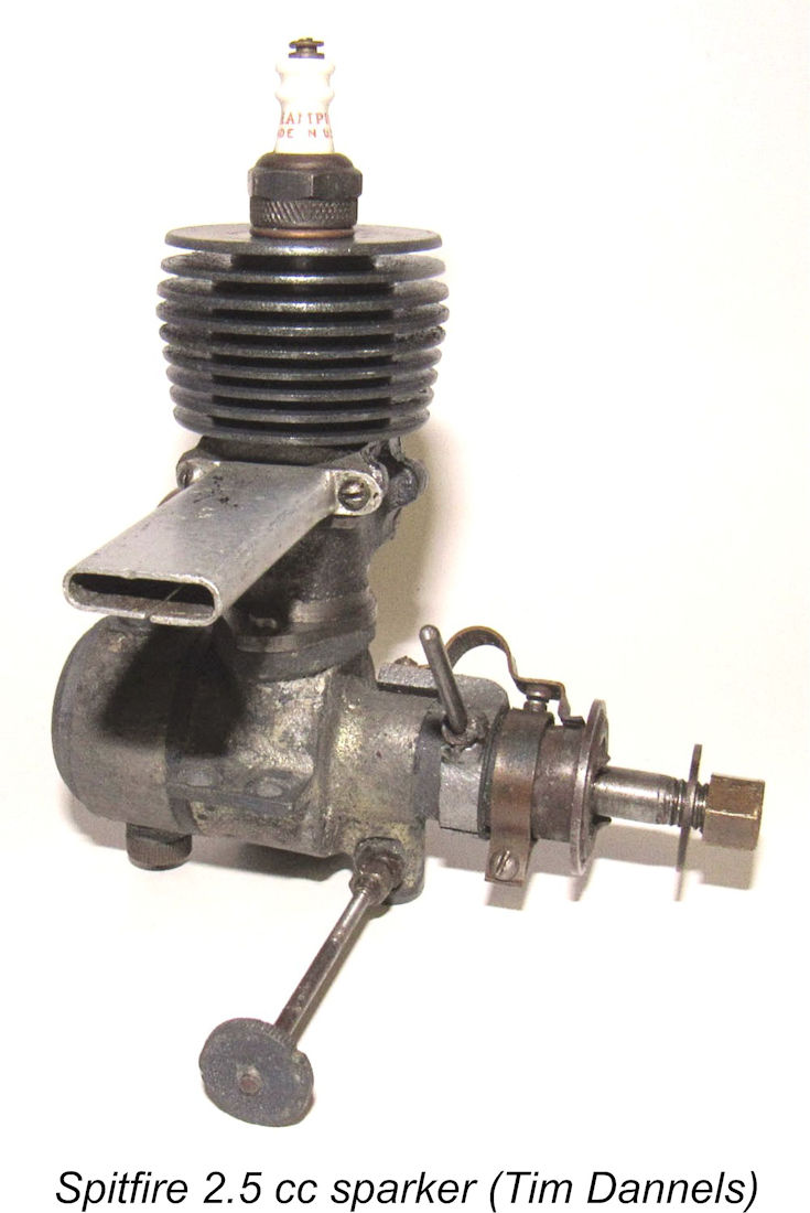
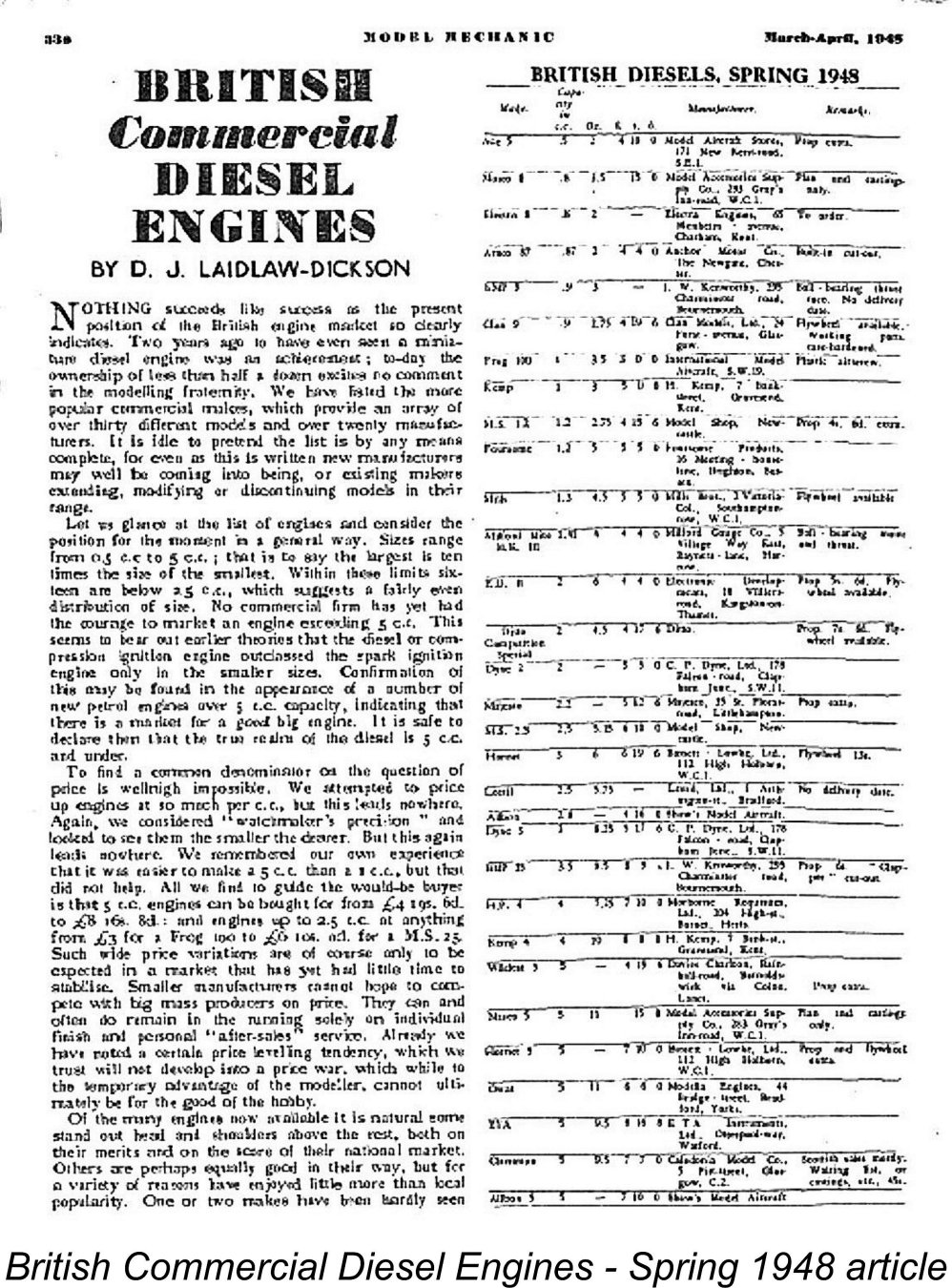
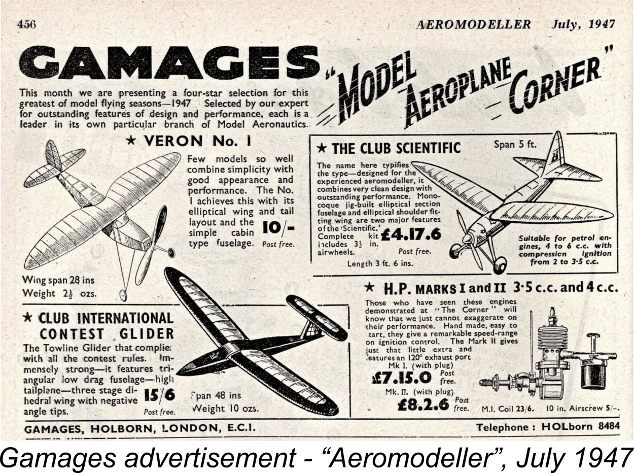
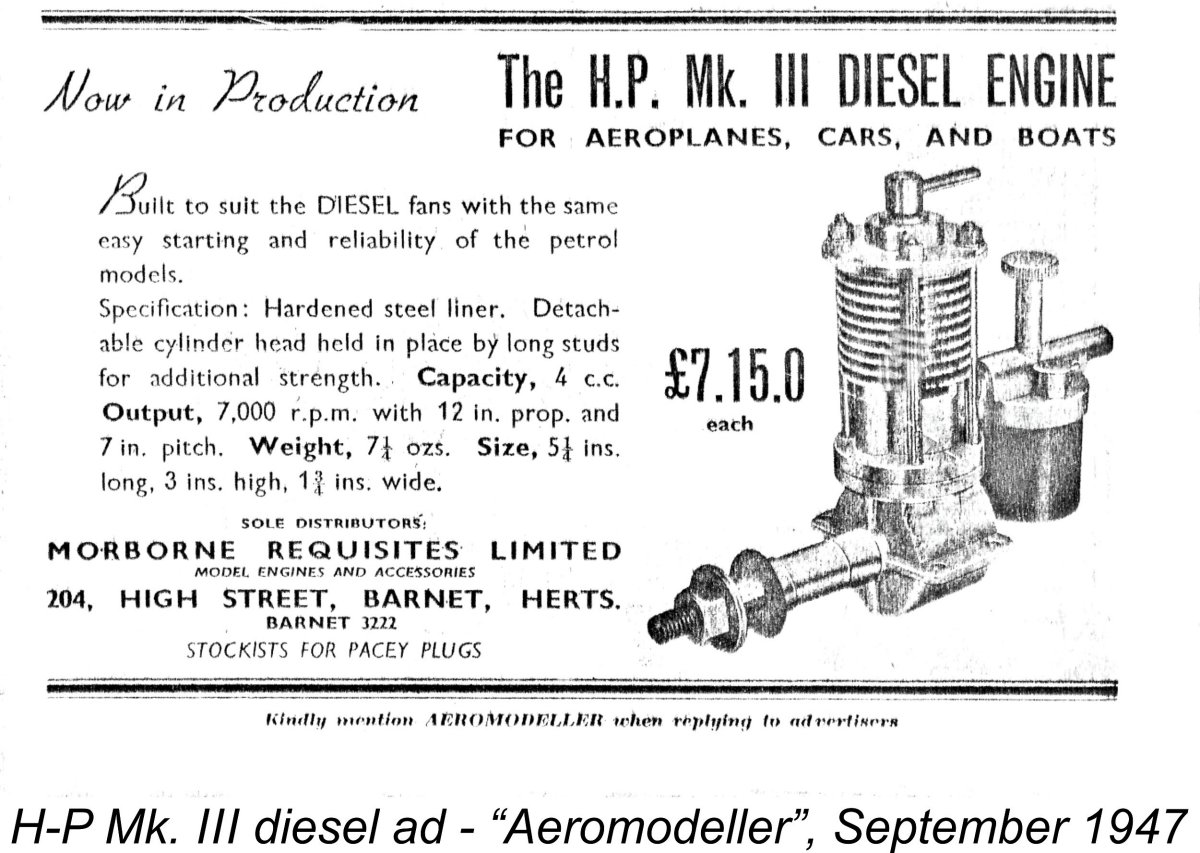
As can be seen, the Atlas turned out to develop around 0.052 BHP @ 5,800 rpm. Any 1 cc diesel of a year or two later would beat these figures. However, we have to remember that this is a pioneering sideport spark ignition design dating from 1946, at a time when British designers were very much in catch-up mode following the enforced WW2 hiatus and made a start by following the pre-WW2 design standards with which they were familiar. It didn't take them long to catch up and begin to move forward, leaving early designs like the Atlas on the sidelines. Even so, the Atlas 3 cc sparker as tested was a perfectly satisfactory model powerplant by 1946 standards for use in free flight sport models of moderate size. An 11x4 prop would suit it perfectly for such applications. Its excellent handling and smooth running would have recommended it to many users as of 1946. It also appears to be quite durable - no mechanical issues of any kind presented themselves during this very enjoyable test. Now, having put the Atlas 3 cc sparker through its paces, we can turn our attention to its successor range - the H-P marque. The H-P Models It was not long after the release of the Atlas Series II variant that a change of manufacturer led to the establishment of our main subject range, the H-P engines. As of December 1946 the Atlas engines were still being displayed by Atlas Motors under that name at the Model Aircraft Exhibition held during that month at Dorland Hall in London. However, in the first part of 1947 the marketing of the Atlas range was taken over by the firm of Morborne Requisites Ltd., who were located at 204 High Street in Barnet, Hertfordshire. The first advertising mention of Morborne Requisites in connection with these engines appeared in the Gamages advertisement of June 1947, which listed the "Morborne 3.5 cc petrol engine". This confirms that the Morborne takeover had occurred by April 1947 at the latest. Most peoples’ first question when discussing this range would probably be – why did Morborne designate these engines as H-P products?!? Isn't that the name of a very popular British "brown sauce"?!? Well, yes, but we're dealing here with model engines, not condiments! The change in the name of the range clearly implies a concurrent change of manufacturer, but the initials bear no relationship whatever to the marketing firm's company name. The confusion in this case arises primarily from the previously-unquestioned identification (by both Laidlaw-Dickson and Mike Clanford among others) of Morborne Requisites as the manufacturers of the H-P engines. In reality, it would seem that they were only the marketing agents for the range. A number of anecdotal sources have combined to identify the actual manufacturers of the H-P engines as a Barnet firm called Henleyston Products. In his excellent and highly recommended pictorial catalogue entitled "British Model Aero Engines 1946 - 2011", Ted Sladden identifies the manufacturers as Henleyston Products of Bruce Road in Barnet, Hertfordshire. Given the role of the Barnet-based Morborne Requisites in marketing the range, this makes perfect sense to me. This identification also makes immediate sense of those pesky initials – H-P stands for Henleyston Products! Case closed as far as I'm concerned ............ Interestingly enough, it appears that the H-P 3.5 cc model was marketed initially as the "H-P Spitfire"! The June 1947 "Aeromodeller" advertising placement from Henry J. Nicholls lists the engine by that name. The same issue carried an entry from Morborne Requisites in the "Classified Advertisement - Trade" section. This entry proclaimed that the "H-P It's clear from the advertising record that the application of the "Spitfire" name to this engine didn't last long - all later advertising reverted to the H-P name without the "Spitfire" designation. This may well have been done to avid confusion with the pre-war Spitfire 2.5 cc sparkie manufactured by Rogers & Geary of Leicester. The latter firm was still very much in business at this time, producing the Stentor 6 cc engines for Model Aircraft Stores Ltd. of Bournemouth. It's actually possible that they retained some level of ownership of the Spitfire name and asked Morborne Requisites to cease applying it to their products. To end any such confusion, the name of the range quickly reverted to just plain H-P, consigning the Atlas marque to model engine history. The Gamages advertisement of July 1947 reflected this name change, offering both the H-P Mk. I and Mk. II spark ignition models by those names in both 3.5 cc and 4 cc displacements. Unfortunately for the hard-working historical researcher, both the Atlas and H-P spark ignition models were pretty much ignored by the contemporary modelling media apart from their advertising appearances. Moreover, such references as do appear are often contradictory. This creates endless headaches when trying to sort out the various models. As summarized above, we seem to have a pretty good handle on the Atlas models, but their H-P successors are another story! It took the mid 1947 arrival of the H-P diesels (of which much more below) to promote some media attention. The H-P diesels were first mentioned in the July 1947 "Aeromodeller" advertisement placed by Henry J. Nicholls, implying that the engines first appeared in May 1947. Both 3.5 cc and 4 cc models were mentioned in this advertisement, both at the same price of £7 10s 0d (£7.50). The H-P diesels arrived on the scene too late to be mentioned by D. J. Laidlaw-Dickson in his ground-breaking late 1946 book “Model Diesels”. Fair enough, but they were certainly around when Col. C. E. Bowden was The first media reference to the H-P range that I can find came through the inclusion of the H-P 4 cc diesel model (see below) in the article by D. J. Laidlaw-Dickson entitled "British Commercial Diesel Engines, Spring 1948" which appeared in the March-April issue of the short-lived "Model Mechanic" magazine (which was edited by none other than our old friend Lawrence H. Sparey). The first page is reproduced at the right. Apologies for the poor quality, but it's the only scan that I could find! I don't have the original magazine issue. The H-P 4 cc diesel appeared in the list of then-current diesel models, but was not mentioned in the text of the article. Laidlaw-Dickson openly admitted that "there remain a host of engines that we have not even mentioned in passing, and readers should not infer any lack of qualities". Presumably space constraints forced the exclusion of many listed engines from the text, including the H-P. The only other contemporary media reference that I can find takes the form of the engines' inclusion in the list of British motors which formed an appendix to Ron Warring’s early 1949 book “Miniature Aero Motors”. Both spark ignition and diesel models are included. Based upon a careful review of their coverage, the compilation of the relevant lists in this book actually seems to have been completed by late 1948 - no engines known to have been introduced after that date are mentioned. One might think that this reference would do much to clarify the identification of the various H-P models. However, this is not the case. Warring seems to have been singularly ill-informed regarding the H-P engines – in fact, the evidence strongly suggests that he never actually had a chance to examine any of them personally. This would explain for example why he was unable to provide any bore and stroke figures, which would have done much to end the confusion regarding displacements. It seems that he was largely presenting information extracted from the manufacturer’s own promotional material. Presumably as a result, none of the H-P engines were included in Warring’s separate table of detailed construction data for British engines. This seems to confirm the suspicion that Warring had not had an opportunity to obtain such data, either from the makers or by direct observation. In particular, he had evidently had no opportunity to take dimensional measurements. This presumably also explains the fact that although the H-P range was included in Warring's table of British motors, the H-P engines were not mentioned at all in the main text. This lack of contemporary documentation brings up a point that needs to be made before I proceed. It has to be admitted that considerable confusion has always existed regarding the identification of the various H-P models. To take just one example, the model identified by Mike Clanford as the H-P Series II diesel in his very useful but at times misleading 1988 “Pictorial A-Z” book is cited by O. F. W. Fisher in his earlier 1977 “Collector’s Guide” as the Series I model! On architectural grounds (see below), I have to side with Clanford on this point, but the contradiction remains on the record. There’s also the issue of displacements, regarding which there's a great deal of confusion. Apart from the seemingly incorrect assignment of a 3.5 cc displacement to the Atlas predecessors of the H-P range, figures of 3.5 cc and 4 cc have been freely applied by different writers to the same H-P model, invariably without presenting evidence based upon direct measurements. A number of these claims are directly contradictory. Henry J. Nicholls added to the confusion by referring to both 3.5 cc and 4 cc models in his July 1947 advertisement in "Aeromodeller". This makes the secure classification of these engines extremely difficult.
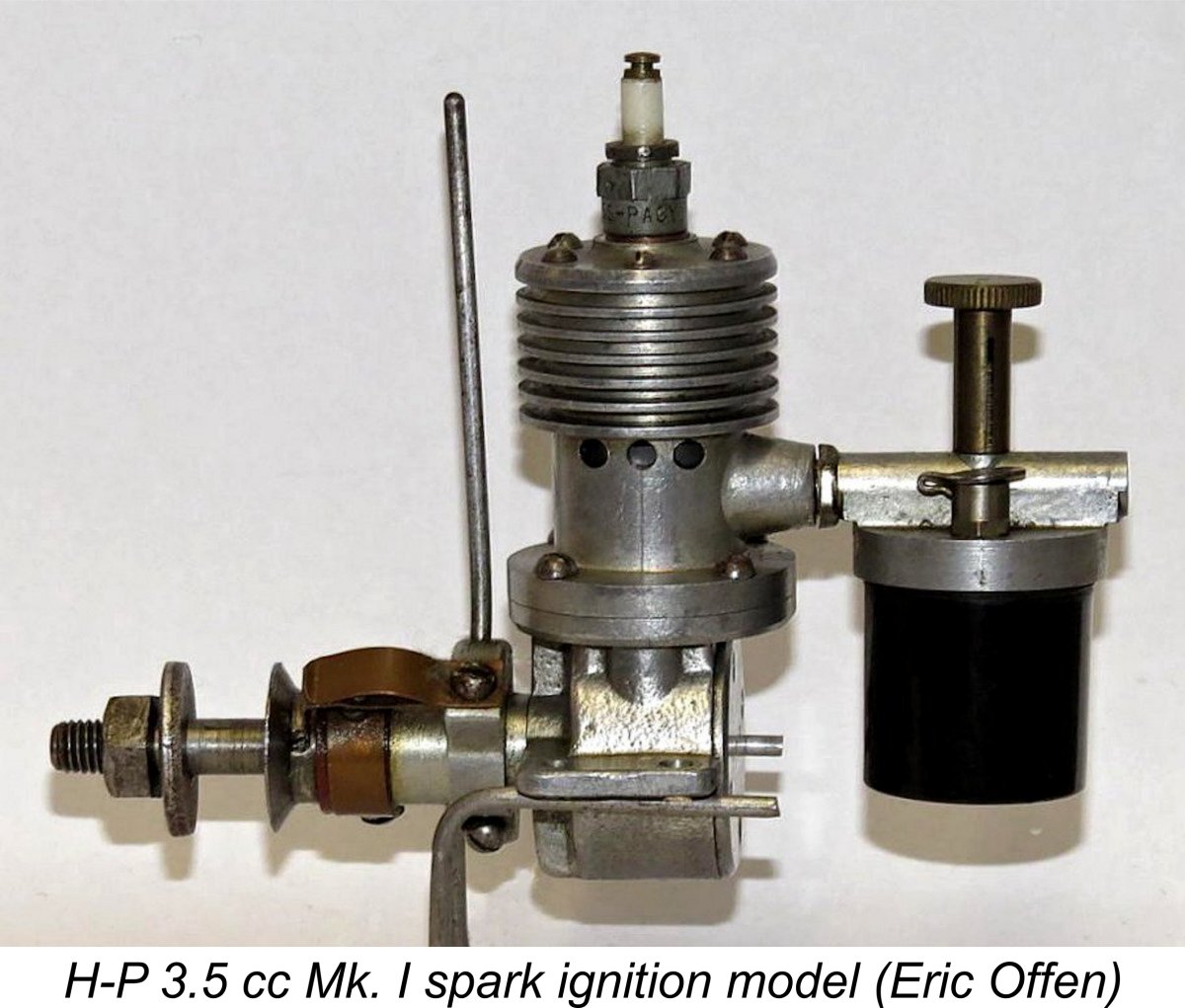
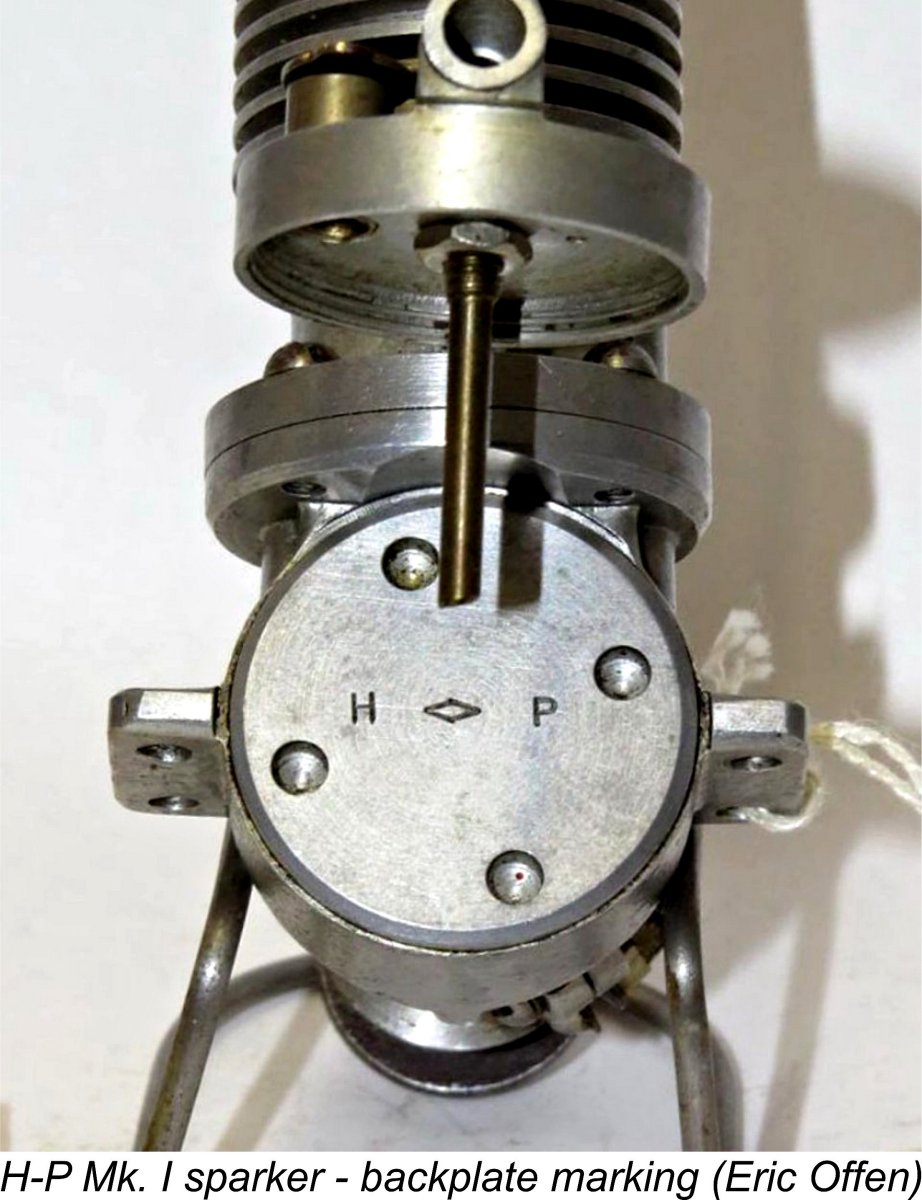
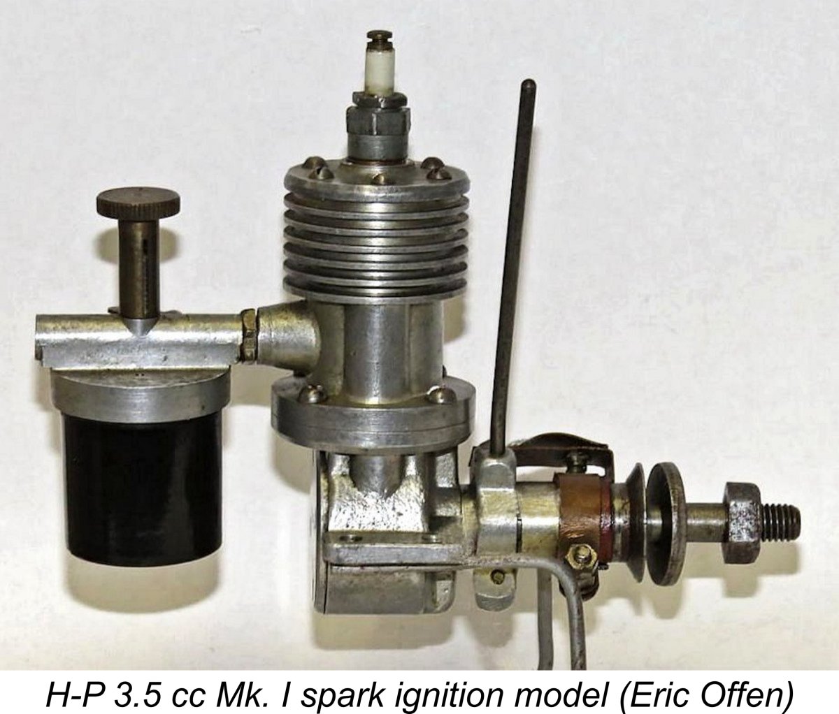
The fact that none of those citing such figures have confirmed that they were based upon direct measurement leaves their claims very much open to doubt. Indeed, they cannot all be correct! Regardless, if at least some of their figures are accurate, an increase in the engines' displacement from their Atlas forebears through bore and/or stroke adjustments is implied. There is actually some fairly persuasive evidence to suggest that this was indeed the case. With the above cautionary comments in mind, let’s take a look at the various models which are known to have been marketed by Morborne Requisites under their new H-P brand name. The first model to be marketed under the H-P banner in early 1947 seems at first sight to have been nothing more than a clone of the late 1946 Atlas 3 cc Series II spark ignition model as manufactured by the original Atlas company in Dunstable. However, the H-P version is invariably cited both by earlier writers and comtemporary Setting the displacement issue aside for the moment, the differentiation between the Atlas Series II and H-P Mk. I models can be a little challenging unless one looks very closely. The most indicative point of comparison is the serial number. The Atlas Series 2 models appear to have carried serial numbers with an A prefix - as stated earlier, my own example bears the serial number A-133. The engines marketed by Morborne Requisites carried serial numbers with an M prefix, presumably standing for Morborne. They also displayed the stamped letters H <> P on their backplates, while the Atlas models were not stamped at all at that location. The illustrated example from Eric Offen's collection bears the serial number M-411 along with the H <> P stamping. Here we encounter the first anomaly when it comes to the identification of these engines. Clanford claims that this model’s Atlas heritage was acknowledged through its being presented as the H-P 3.5 Series III model, thus continuing the Series designation begun by Atlas. However, this is at variance with the data presented by Warring, who made no mention of an H-P Series III sparker, instead listing both Mk. I and Mk. II (not Series I and II, note) variants of the H-P spark ignition model.
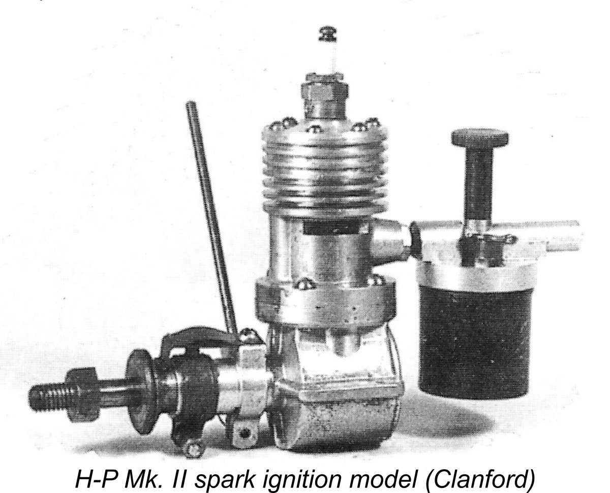
Warring’s version is further supported by the fact that the H-P spark ignition model is undoubtedly encountered in not one but two quite distinct variants. The first of these (presumably Warring’s H-P Mk. I model) is essentially identical to the Atlas Series II design. It retains the three drilled exhaust apertures placed on the left side of the cylinder opposite the single bypass and transfer porting, which was still located on the right hand side. It looks more or less identical to the Atlas Series II model. Eric Offen’s previously-illustrated example, which is unquestionably an H-P Mk. I model, bears the serial number M-411. The stamped initials H-P on the backplate confirm its H-P origin. The other variant (presumably the later H-P Mk. II model) features completely redesigned cylinder porting. The upper Unfortunately, it was also this model which was identified by Mike Clanford as the H-P Series III design. I’m personally convinced that this is incorrect and that it is in reality Warring’s H-P Mk. II model. Its later date than the unit which I believe to be the Mk. I is effectively confirmed by the fact that all of the later diesel models used the same re-configured upper cylinder design with a forward bypass and twin exhausts, one on each side. One matter in connection with which Warring’s evidence initially created some further confusion (as if we didn't have enough already!) is our old bugbear of displacements. Warring cited the displacements of the Mk. I and Mk. II variants of the H-P spark ignition model as 3.5 cc and 4.0 cc respectively. This clearly implies a Thankfully, some clarification is available on this matter in the form of an advertising placement by the London department store Gamages which appeared in the July 1947 issue of "Aeromodeller". This advertisement appears to offer authoritative confirmation of Warring's views. The panel covering the H-P engines confirms that both Mk. I and Mk. II variants of the H-P spark ignition model were simultaneously available at that time. More importantly, the displacement of the Mk. I version was cited as being 3.5 cc, while that of the Mk. II variant was quoted as being 4.0 cc. This is in complete accordance with Warring's claims. My sincere thanks to Maris Dislers for digging this advertisement out from his magazine collection. One might question why an increase of only 0.5 cc would be viewed as sufficient justification for the release of a different variant. However, it's important to realize that the differences between the Mk. I and Mk. II variants went well beyond their respective displacements. It would appear that the manufacturers saw a need to offer a revised model having a higher performance than the Mk. I version. The increased displacement was only one of a number of design changes clearly aimed at achieving this objective. Overall, the change in identification was clearly quite justified. The picture of the engine in this advertisement is clearly a Mk. I example. The panel mentions the fact that the Mk. II variant had a different exhaust porting arrangement, which is completely consistent with the information set out above. Somewhat strangely, the Mk. II version was said to feature a "120 degree exhaust port". The total annular space occupied by the twin exhaust ports of the Mk. II does indeed add up to around 120 degrees (60 degrees apiece), but this is a rather odd way of putting it! The Mk. II version was said to offer "just that little extra". At a premium price of £8 2s 6d (£8.13), it certainly should have done so!!
Clanford cited the displacement of the H-P Series III sparker (which I believe to be the H-P 4.0 cc Mk. II model) as 3.5 cc (.212 cuin), although he presented no bore and stroke dimensions to back this up. According to Warring, the engine (which he called the H-P Mk. II, remember) had an actual displacement of 4.0 cc and weighed 7.5 ounces (213 gm). Its selling price was given by Warring as as £7 10s 0d (£7.50) – down a little from the 1947 price quoted in the Gamages ad, but still a serious chunk of change in 1948 Britain when Warring was writing his book. This talk of prices highlights a point which needs to be made here. As of early 1947 model engine prices had not begun their subsequent readjustment to more closely reflect the purchasing power of the average potential customer in Britain, at least in the larger displacements. Companies such as IMA (FROG) and E.D. were leading the way in that direction with their far more economically-priced models, but at this point those companies were strictly involved with smaller engines of 2 cc or less. If you wanted a larger displacement engine, you had to look elsewhere and be prepared to pay for the privilege.
By 1950, most of the smaller-scale manufacturers listed earlier (including H-P) had vanished from the scene, significantly reducing the diversity of model engines remaining available to British modellers. The British model engine marketplace was never again to offer the number and diversity of different marques and individualistic designs which had peaked during the latter part of the 1940’s. 1947 marked another watershed for the British model engine manufacturing industry, because it was in that year that the spotlight shifted decisively from spark ignition to diesel. From 1947 onwards, few manufacturers introduced new spark ignition models – in fact, many existing sparkies were withdrawn from production in that year or soon thereafter. There were exceptions, of course, most notably in the large racing engine field with spark ignition versions of such units as the Rowell 60, Ten-Sixty-Six Conqueror and Nordec R10, but these were the exceptions. From this point onwards, diesels dominated the British modelling scene, as they were to do for several decades to come. It’s very clear that the promoters of the H-P range recognised this emerging trend, because they appear to have been very quick to switch their development focus from spark ignition to diesel. The two spark ignition models noted above (by whatever name!) were the last to appear under the H-P banner - from mid 1947 onwards, the manufacturers focused their attention strictly upon diesels.
Like its spark ignition companion in the range, this model was included in Ron Warring’s table of British motors in his previously-mentioned book. However, its identification was greatly confused (yet again!) by some inconsistent data which appears in Warring’s table. For one thing, the engine was identified as the H-P Mk. IX model. This identification is in no way consistent with what is known of the H-P nomenclature in general. (Sigh - here we go again ........!!). To make matters even more confusing, Warring cited a displacement of 0.208 cuin., which converts to 3.4 cc. Fair enough, but he then muddled things even further by rendering this displacement in its metric form as 3.9 cc (0.238 cuin.)!! Clearly another example of an unedited misprint – the two figures cannot be reconciled. It would appear that the 3 in the engine's actual displacement in cubic inches was incorrectly rendered as a 0 by the typesetter. Unfortunately, Warring once again stopped short of providing bore and stroke data, leaving us with no way of resolving this anomaly. He did however quote the engine’s weight as 6.5 ounces. The selling price was recorded as £6 10s 0d (£6.50) – a worthwhile reduction from the price of the earlier sparker. This unit once again raises the thorny issue of model identification mentioned earlier. In his 1977 “Collector’s Guide”, O. F. W. Fisher claims that the H-P Series I diesel (as he calls it) featured four studs which secured both the cylinder and the head. By contrast, Clanford’s illustration of the four-stud variant is identified as the H-P Series II diesel (see below), with a cited displacement of 4.0 cc. I have to say that apart from the use of a Series number as opposed to a Mark number, the architectural evidence seems to support Clanford’s model identification, at least as far as the Mark number goes. I base This appears to confirm that the first H-P diesel was simply a diesel conversion of the sparker, just as claimed by Clanford. Apart from the omission of the timer and the addition of a contra-piston, the most obvious external changes were the addition of a pair of strengthening buttresses at the sides of the upper cylinder casting below the exhaust ports as well as a vertical extension of that component to accomodate the extra cylinder length necessitated by the addition of a contra-piston. Later in 1947, a revised diesel model was introduced as the H-P Mk. II diesel. The unit illustrated by Clanford in his "A-Z" book and reproduced at the left is captioned as this model. However, the waters are seriously muddied by the fact Of equal interest is the advertisement's claim that the engine had a displacement of 4 cc. We need not split hairs over the question of Mark versus Series numbers except to say that the manufacturers themselves appear to have used the Mark numbering system very consistently. Whatever its true designation, in structural terms this model seemingly represented an effort on the part of the manufacturer to beef up the design somewhat. The most obvious external evidence of this is the switch from a machine screw assembly for the cylinder and head to the use of four sturdy-looking steel studs which secure both components. And it didn’t stop there – the main bearing housing too was considerably strengthened through the provision of a conical expansion at the crankcase end, which served in effect as a 360 degree buttress to increase the strength of the bearing. It must be admitted that this was a logical move – the un-reinforced configuration seen on the earlier Mk. I converted sparker does seem rather vulnerable to crash damage. It is this change in the configuration of the main bearing that convinces me that the four-stud model did indeed follow on the heels of the original Mk. I spark ignition conversion with its unbraced main bearing. It’s hard to see the designer going from a far stronger main bearing to a significantly weaker one and then back again. While the modification to the main bearing housing is readily understood, the same cannot be said of the switch from machine screw assembly to studs for the cylinder. The revised design seems to represent a step backward by adding an additional element of complexity along with a negative impact upon the engine’s aesthetic appeal. There must surely have been a reason for this design change, but at this distance in time it's a little difficult to discern! My valued Scottish mate Don Imrie has credibly suggested that this change may relate to temporary difficulties in securing a supply of suitable machine screws. Such fastenings may have been in short supply for a time, leading to a switch to the use of studs, which were easily manufactured in-house. A very plausible suggestion from Don, although there's no way of proving it to be true.
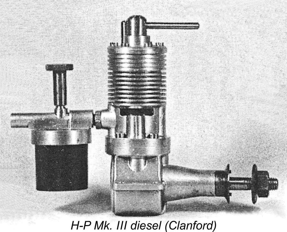
By early 1948, what was to prove to be the final H-P model – the so-called 4 cc Mk. III diesel (or Series III if you go with Clanford) - had undoubtedly made its appearance. Both Fisher and Clanford are (for once!) in agreement with the engine’s Series III identification, although Warring stays true to the Mk. designation which he applied to the other H-P models, designating this unit as the H-P Mk. III diesel. Since my own example is clearly factory-stamped "H-P MK 3", I'll go with Warring on this point........... All three sources also agree upon the engine’s displacement, which they all cite as 4.0 cc. Finally, we have unanimity all round! However, once again none of the above sources provides any bore and stroke data to allow the stated displacement figure to be checked. The H-P Mk. III diesel (or Series III diesel if you insist!) was actually little changed from its predecessor in external design terms. It retained the strengthened main bearing housing of its predecessor. The most obvious visible change was its reversion to the far neater machine screw assembly for the cylinder and head. Presumably the beefed-up and more costly construction using steel studs had been found through operational experience to be unnecessary. Alternatively, the supply situation with respect to suitable fasteners may have eased.
The measured example has nominal bore and stroke dimensions of 21/32 (0.656 in. - 16.67 mm) and 5/8 (0.625 in. - 15.87 mm) for a design displacement of 3.46 cc. The actual carefully measured (and repeatedly re-measured) bore and stroke dimensions of this example are 0.658 in. (16.713 mm) and 0.622 in. (15.798 mm) respectively – well within reasonable tolerance limits for small-scale production using the presumably worn-out wartime equipment which most early post-war British manufacturers were forced by economic considerations to rely on. Regardless, this particular example of the “4 cc” H-P Mk. III (or Series III) diesel is indisputably a 3.5 cc unit! It is of course possible that the Mk. III diesel was made in both 3.5 cc and 4 cc form, being bored or stroked out to 4 cc, although one would have to wonder why .......... however, there’s currently no hard evidence to settle this question one way or the other.
Production of this model seems to have continued into 1949, but almost certainly ceased quite early on in that year as far lighter, less costly and more powerful models progressively appeared from competing manufacturers. The final advertising appearance of the H-P engines was their inclusion in the August 1948 placement by E. Law & Son, in which the H-P Mark III 4 cc diesel, Mark IX 3 cc diesel and Mark II petrol units were all mentioned. The implication here is that the otherwise-undocumented H-P Mk. IX diesel mentioned by Warring did in fact exist. How much more confusion can my tired old brain take?!? The H-P spark ignition engines did make one more promotional appearance. The "Trade" section in the September 1948 issue of "Aeromodeller" included the following statement: “8, 4c.c. petrol engines "H.P." Mark II unused, £3 15s. 0d.(£3.75) each. 150 1/4in. Pacy plugs at 2/- each. For particulars apply Morborne Requisites Ltd., 204, High Street, Barnet, Herts.” It would appear that as things were winding down, Morborne found themselves holding a stock of eight unsold examples of the H-P Mk. II sparkie along with some 200 Pacy spark plugs which had presumably been purchased as a lot to be fitted to newly-manufactured engines but which were never used given the collapse of demand for the sparkers. Morborne were clearly liquidating remaining assets, but couldn't sell these items through their normal retailers, presumably as a result of the general diesel "takeover". It seems highly doubtful that the number of H-P diesels produced reached four figures. Whatever the final tally, the termination of production of the H-P Mk. III diesel signaled the end of the H-P range after only two years on the market under that brand-name. The H-P engines all appear to have borne serial numbers. Eric Offen’s H-P Mk. I sparker bears the number M-411, while my own H-P Mk. III diesel is numbered D-654. Fisher illustrated a seemingly identical Mk. III diesel which bore the number D-218. The letter evidently identifies the particular series to which the engine belongs, while the number presumbly indicates the engine's place in the production sequence for that series. In each case, the letter is stamped beneath the right-hand mounting lug (looking forward in the direction of flight) while the number is stamped in the corresponding location beneath the left-hand lug. Taken together, these numbers seem to imply that at least 411 examples of the sparkie and 654 examples of the diesel were made. If we factor in the Mk. II sparker and the Mk. I and Mk. II diesel models, we might reasonably postulate a total production figure of some 2,000 engines, taking all known H-P models into account. This in turn implies a relatively small-scale manufacturing operation with only a handful of employees producing some 80 engines monthly on average over the two-year market tenure of the H-P range. Of course, the possibility also exists that the spark ignition engines produced following the Morborne take-over simply continued the numerical sequence initiated by Atlas Motors, with only the letter prefix being changed. If this was the case, the total number of engines suggested by the serial numbers would be somewhat reduced. We'll doubtless never know ................ The fact that Fisher quoted a displacement of 4 cc for his illustrated diesel example is interesting. It would appear from the admittedly scanty evidence available so far that the manufacturers used a different letter to denote engines in a given series. This being the case, the fact that the two diesel examples (mine and Fisher's) are serial-numbered in the same sequence seems to me to make it unlikely that different displacements were involved – surely a larger 4 cc model would be assigned to a different serial numbering sequence having a different identification letter? One wonders if Fisher actually took measurements from his example ………… That’s about all that can be gleaned about these engines from a review of the scanty, incomplete and often contradictory documentary evidence. To learn more, we have to turn our attention to the engines themselves. Let’s make a start by examining the single example of an H-P engine that is currently on hand for examination – the Mk. III diesel, in this case of confirmed 3.5 cc displacement. The H-P Mk. III Diesel Described
This example bears the serial number D-654, with the three-digit number being stamped under the left-hand mounting lug (looking forward in the direction of flight) and the letter “D” stamped on the underside of the right-hand lug. The backplate is stamped with the identification “H-P MK 3” as written. No identification markings are cast onto the engine at any point. The H-P Mk. III is in essence an entirely typical sideport diesel of its era. Its main distinguishing feature is its use (in this 3.5 cc example) of short-stroke power train geometry. As noted earlier, the measured bore and stroke of this engine are 0.658 in. (16.713 mm) and 0.622 in. (15.798 mm) respectively for a displacement of 3.47 cc (0.212 cuin.). The engine weighs in at 8.08 ounces (229 gm) - a lot of weight for a 3.5 cc engine, even by 1948 standards.
The steel cylinder liner drops into the upper cylinder casting, semingly being shrunk into position. It is topped with a turned alloy head which is secured once again by machine screws. The contra piston is also of steel. Here we encounter one of the engine’s more unusual design features. The comp screw is not threaded though the cylinder head in the normal manner – instead it simply passes from below through an unthreaded drilled hole in the head and is located in position vertically by a shoulder formed above its lower threaded length. It is thus free to turn in either direction while remaining at exactly the same elevation relative to the head. The external cap of the comp screw is a separate component which is retained by the single control arm.
A little further thought should convince the reader that the left-hand thread will result in the comp screw working exactly as in the more conventional arrangement – turning it clockwise (viewed from above) will increase compression, and vice versa. Excellent justification for the use of a left-hand thread! The other effect of this arrangement is that it provides positive control of the contra piston in either direction – turning the comp screw anti-clockwise (viewed from above) will pull the contra piston up on its thread with no help needed from internal gas pressure in the cylinder. In other words, this design gives the comp screw a positive two-way effect. This could be quite handy during starting after prolonged storage. As received, the contra piston in this example was extremely loose. This may be explained by the fact that it is made of hardened steel – a contra-piston of this material has a well-known tendency to stick in a steel bore when hot. Steel contra pistons were often fitted a bit on the loose side to compensate for this. In this instance, the designer may also have been relying on the two-way positive control provided by the comp screw arrangement to keep things in place when running. If so, the manufacturers went a little too far with this example! A test run of the engine soon after it arrived showed that although the contra-piston sealed well enough, it would not hold a setting when the engine was running, even when hot. This made the establishment and maintenance of precise settings very difficult, even under bench test conditions. For use in the field, one would have to devise a means of securing the comp screw once a setting was established. For this reason, I ended up making a properly-fitted replica contra piston out of cast iron. This worked perfectly on test, allowing the engine to be adjusted very precisely, after which it would hold its setting securely.
Moving downwards, the exhaust chores are handled by two monumentally large milled apertures placed one on each side. The transfer ports consist of a row of three small drilled holes placed at the front of the cylinder between the exhaust ports. These are fed through a generously-dimensioned bypass passage formed in the interior of the crankcase at the front. The transfer ports overlap the exhaust ports almost completely. The induction port at the rear of the cylinder between the exhaust ports is a milled rectangular opening of considerable area. In conjunction with an intake tract of seemingly adequate diameter, the engine's breathing requirements appear to be well provided for.
The piston drives what appears to be a one-piece steel crankshaft through a seemingly very sturdy cast alloy con-rod. The bearings at both ends of this component are of more than adequate length. In particular, the full-length small end bearing doubtless contributes to the ability of the rather skinny gudgeon pin to deal with the loads imposed upon it. The standard of fitting is exceptionally good – almost no play can be detected.
Another somewhat questionable design feature (in my personal view) is the means of keying the steel prop driver to the shaft. This is accomplished by means of a small set-screw which engages with a blind hole in the forward extension of the crankshaft. The idea is presumably that in a hard crash the set screw will shear, thus preventing the development of potentially damaging stresses in the shaft itself. However, the screw seems to be a bit on the undersized side, hence appearing vulnerable to wear even in normal service. Moreover, the required hole in the shaft appears to create a stress concentration point in that component which may defeat its original purpose. The carburetor/tank assembly is connected to the cylinder intake stub through an externally threaded brass nipple. E.D. used a similar carburetor mounting system on the early variants of their 2 cc Mk. II diesel. However, they experienced a lot of trouble with breakages, hence switching to a more sturdy arrangement quite early on. I’d expect the H-P component to be similarly vulnerable. However, the consequence of a breakage is merely the fitting of a new replacement brass nipple. The quality of the engine’s construction is very high, particularly where it counts. All working fits are exceptionally good. With the proviso that the seemingly undersized gudgeon pin might give trouble over time, I’d expect this engine to give long and dependable service if handled respectfully. If they were all as well-made as this example, the H-P range would certainly count as one of Britain's higher-quality marques from the early post-war period. Fair enough – so here we have a very well-made and generally well-designed model diesel, albeit one which could benefit by going on a diet! How does it run?? Let’s find out!! The H-P Mk. III Diesel on Test
I was expecting this engine to be a low-speed torque producer rather than a powerhouse, selecting my props accordingly. As it turned out, the range of props that I did select neatly bracketed the region of the engine's peak output. Since the fitting of a new contra piston meant that I didn't have any idea of the range of compression settings that would be required during the new round of testing, I began with a standard 8BA machine screw in place of the compression stop pin which normally does double duty as one of the head retaining screws. I installed the H-P in the test stand, fitted an 11x7 Zinger wood prop and got right down to it. Since the engine had not been run for some years, it was rather full of storage oil. A small prime was required to get it to fire up and blow this out of the system. I also made life difficult for myself by guessing very much on the rich side as far as the needle setting went, flooding the crankcase as a result. However, it didn't take long to work through these difficulties and get the H-P running. Once the required range of compression settings was established, I re-installed the stop pin in the appropriate location. From that point onwards, it was all systems go!! The engine proved to be almost absurdly easy to start, never requiring another prime either hot or cold. A single choked flick was the only necessary preliminary, after which a few more flicks invariably resulted in a start. I found it best to open the needle about a quarter turn for cold starting, but hot re-starts were immediate at running settings. The test was further enhanced by the engine's excellent Once set, running qualities were all that could be desired. The engine ran very steadily without missing a beat. It also displayed no tendency to sag as it warmed up. The exhaust residue was completely clear at all times, indicating good combustion characteristics along with very well-mated moving parts. No trace of any issues with the engine's working components manifested itself at any time during a long and at times arduous test. In particular, that very skinny gudgeon pin behaved itself perfectly! A particularly welcome finding was the fact that (as anticipated) vibration levels were relatively low, no doubt due to the combination of a short stroke, comparatively lightweight reciprocating components and a generously counterbalanced crankweb. I had no compunction about running the engine well past its peak - indeed, it was quite happy to run at such elevated speeds, albeit of course with a reduced power output. Starting remained exceptionally good on all props tested. Overall, I'd rate this as one of the most enjoyable tests that I've conducted for some time. I was enjoying running this fine engine so much that I forgot for a while that I was supposed to be checking it out on different props! I did however get back to the task at hand, testing a range of loads which proved to bracket the peak very nicely. The figures obtained were as follows, together with the derived power curve:
As can be seen, the H-P delivered a very solid performance by the standards of its day, developing some 0.130 BHP @ 6,400 rpm. Plenty of low-speed torque on tap! The range of props which it would turn effectively was quite impressive - it was developing over 0.120 BHP at all speeds between 5,200 and 7,200 rpm. Any prop that held it to within that speed range in flight would be quite effective in service. For free flight use, I'd probably opt for something like a 12x5, while in control line service a 10x8 would probably work well. The engine came through its test with flying colours, seemingly ready to keep running as long as required and then some. Although it is undeniably a bit of a lump for the power that it develops, I'd have to rate this as a pretty solid effort on the part of Henleyston Products! Conclusion
Another factor which doubtless played its part was price. It would appear that the prices of the H-P engines were never really competitive in the context of the purchasing power of the average early post-war British aeromodelling enthusiast. There's little doubt in my mind that the quality of the engines fully justified their high prices, but manufacturers could only get away with playing the pay-for-quality game if they were servicing a niche market whose participants had reason to value quality to the point where they were willing to pay a premium price for it - the Olivers are perhaps the most famous examples of manufacturers whose performance-oriented customers valued quality to such a point. The potential buyers for the H-P engines were not in this category - they were essentially sport fliers who just wanted a dependable engine which could be bought at an affordable price. The H-P engines fulfilled the first requirement admirably, but came nowhere near meeting the second of these criteria. Presumably significant price reductions could only be achieved through a sacrifice of quality, something which the H-P manufacturers were evidently unwilling to contemplate. This impression is reinforced by the extremely thin advertising history of the H-P Mk. III diesel. Following its introduction in mid 1947, the sole advertising placement by the distributor came in September 1947 as mentioned earlier. Thereafter, its advertising appearances were confined to its inclusion in placements by various model shops. It was listed by Bud Morgan in December 1947, by N. and K. C. Keyser (K's) of London in January and February 1948, by Arthur Mullet in April 1948 and by Bud Morgan in June 1948. Its final appearance in a model shop listing came from E. Law & Son in August 1948. The engine thus seemingly had a promotional life of less than a year. Still, hats off to Henleyston Products for producing a range of model engines which displayed both better-than-average quality along with more than adequate performance for sport-flying use. They may not have lasted long in the marketplace, but these fine engines are definitely worth remembering! _____________________ Article © Adrian C. Duncan, Coquitlam, British Columbia, Canada First published February 2016 Updated January 2020 Second update February 2020 (test of Atlas 3 cc sparkie) Third update October 2022 (further chronological details)
|
||
 In this article I’ll attempt to summarize what I’ve been able to discover about the H-P range of model engines from the early post-WW2 period in Britain. I hasten to point out that these engines have nothing whatsoever to do with the far later HP engines made by Hirtenberger Patronen of Austria from the early 1960's to the late 1980's! The coincidence of the two companies' trade-names causes some confusion, but it is merely a coincidence! Moreover, the pioneering British range came first by a good margin of time.............
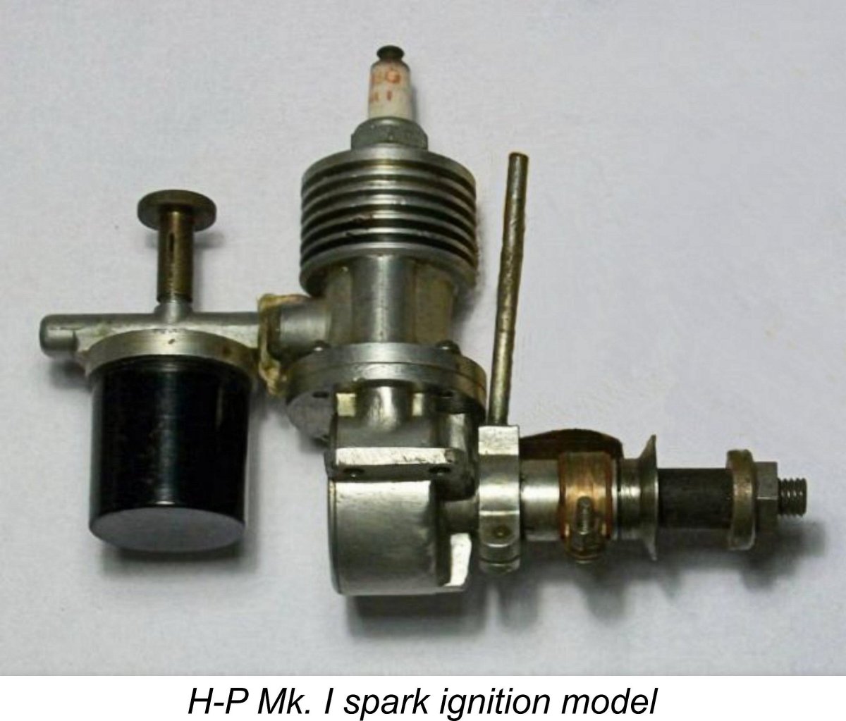 Indeed, I’m painfully aware that at present I actually know relatively little about the background to this rather obscure range. However, I would very much like to know more! Accordingly, this is one of those articles which I’m putting up here primarily in the hope that it may encourage others to share what they know or are able to deduce from an examination of examples in their possession. Any additional information received will be added to the following text with both grateful thanks and full acknowledgement! This article therefore represents no more than a start in recording the history of this range - much of it remains to be written in the future.
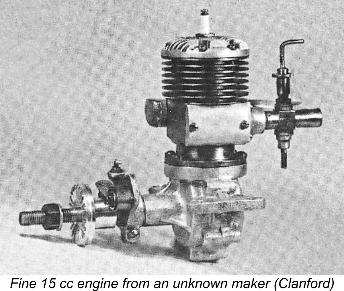
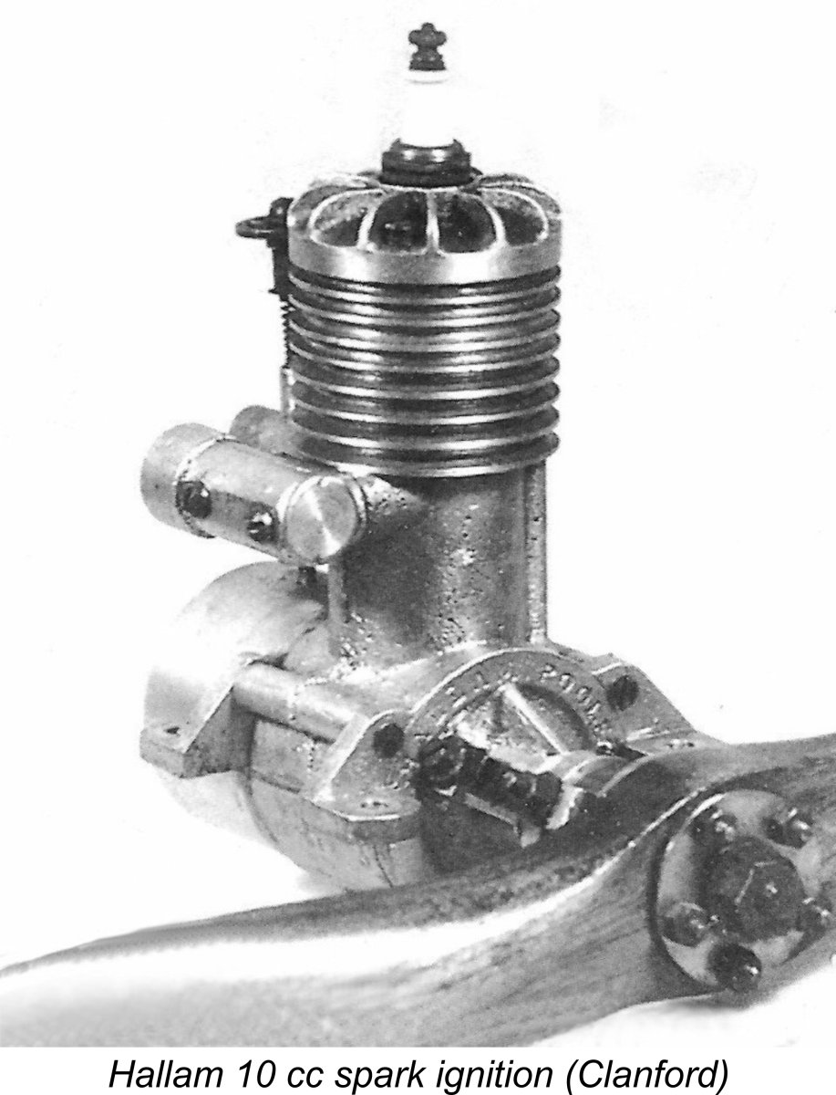 surprising diversity of model engines both before and after the war. There was also the remarkably prolific Leicester-based firm of Rogers & Geary, who produced the pre-war Spitfire 2.5 cc, Hornet 3.5 cc, Wasp 6 cc and (post-war) Stentor 6 cc engines for Model Aircraft Stores Ltd. of Bournemouth, later to become famous for their Veron range of model kits.
 Scandinavian countries which for one reason or another were not directly affected by the fighting. By the end of the war the model diesel had been developed into a formidable competitor for the “traditional” spark ignition models. Word of these developments quickly spread to Britain during the latter stages of the war.
 However, there was an area in between the major producers and the small-scale artisan operations which lay open to modest-scale series producers of engines for marketing primarily in their own specific geographic areas. Firms which entered the market on such a mid-scale regional basis during the early post-war period included the Anchor Motor Co. of Chester with their
 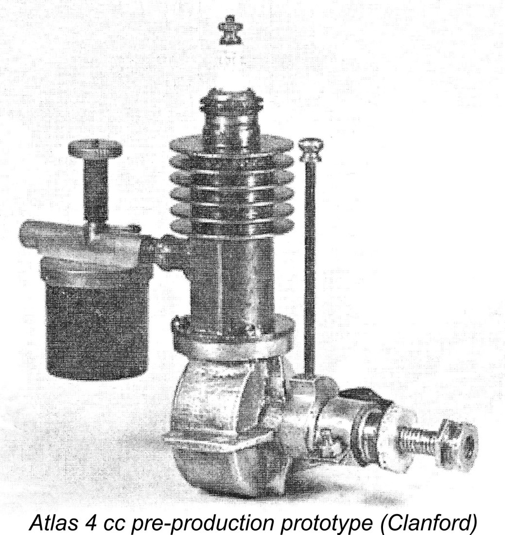 ose involved were familiar, at least initially. In many ways this was an inevitable consequence of model diesel development in Britain having been sidelined during the war years due to other priorities, while development in a number of occupied or neutral Continental countries had proceeded rapidly. This of course left British diesel designers playing catch-up at the outset, a game which they were to play very successfully, as history shows.
 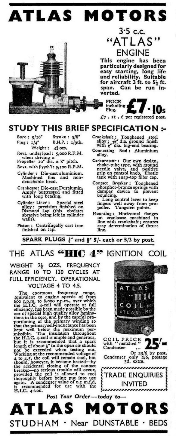 Atlas was among the firms which focused initially on the development of spark ignition engines designed very much along pre-war lines. Given the relative scarcity of information about the activities of this company as well as the many inconsistencies in the information provided with the advertisements, there’s not a lot of authoritative detail that can be shared.
 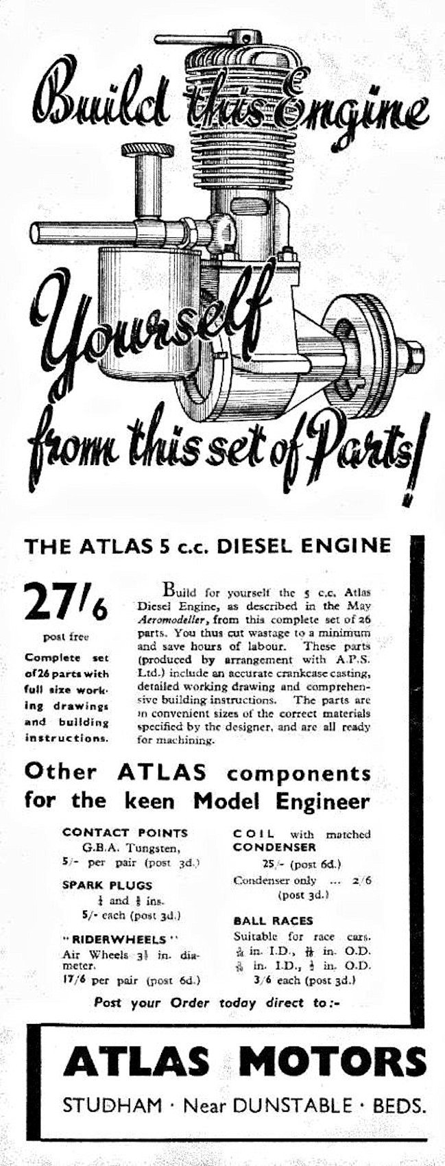 By mid 1946, Atlas Motors had became involved with model diesels, albeit not with a design of their own. In mid 1946 they began to advertise sets of plans, castings and
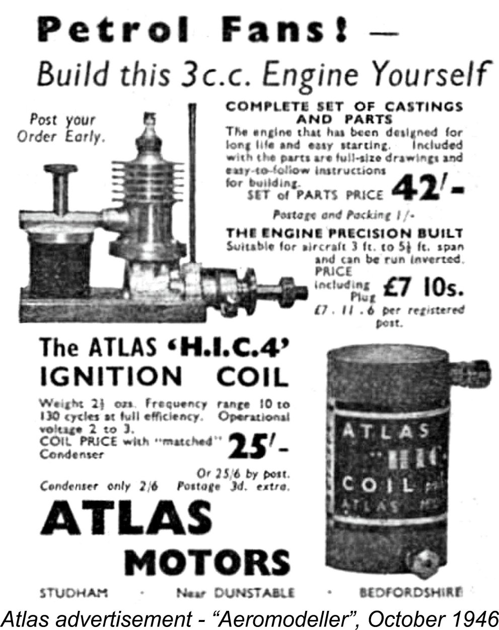
 For reasons which defy our understanding given their consistent use of metric displacement figures expressed in cc, British designers of the period preferred to work in fractional inch dimensions. I've measured and re-measured my pristine example of the Atlas Series II model, consistently coming up with nominal bore and stroke dimensions of
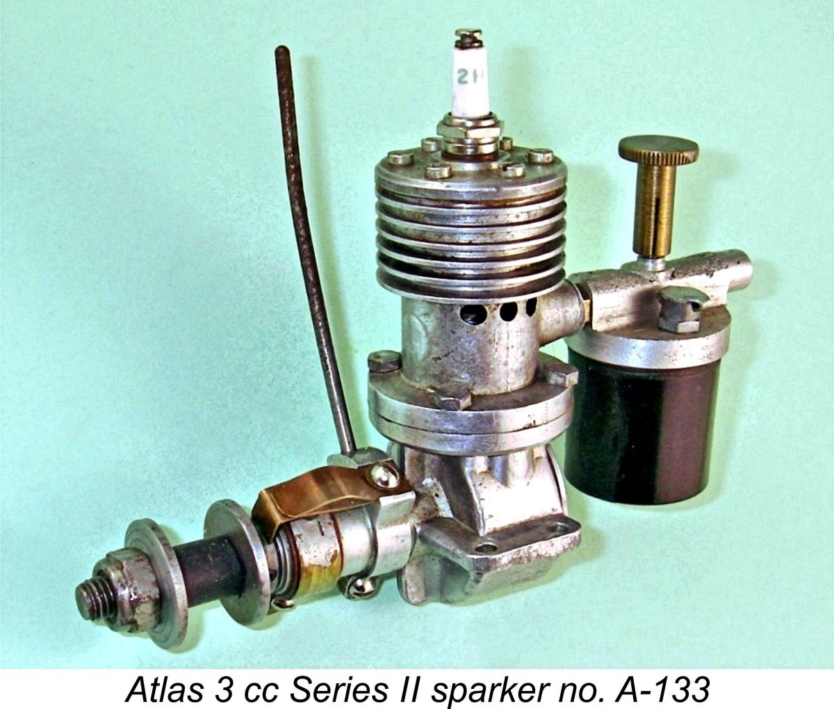
 Of course, nothing to do with the identification of the H-P engines is ever straightforward or unambiguous! Our friend Fisher adds to the confusion by specifically referring to the H-P Mk. II sparker as a 3.5 cc model, in direct contradiction to both Warring and the Gamages advertisement. AAARRRGGGHHH!@?!! This issue of displacements is one of the great uncertainties relating to the secure identification of these engines – we get no help at all from the various literature sources, or for that matter from the engines’ external features.
 British modellers had to wait until 1949 for the appearance of less expensive engines in the displacement categories above 2.5 cc (0.15 cuin.). When this did begin to occur, there was of course a price of a different kind to be paid – few of the smaller-scale or “artisan” manufacturers listed earlier were able to remain competitive. It was the economy of large-scale production that allowed the achievement of lower prices by the major manufacturers. Those lower prices meant that few of the garden-shed and low-volume operators could make economic sense out of remaining in business.
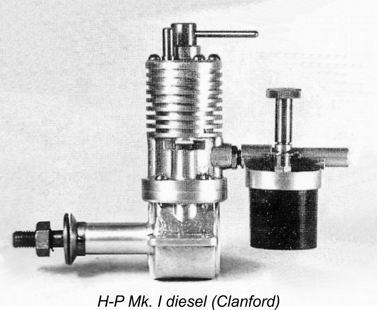 The first H-P diesel was the Mk. I model (or Series I if you believe Clanford on this point). This model seems to have reached the market around mid 1947. All sources agree that this engine was a direct development of the earlier H-P Mk. II spark ignition design. This makes it appear not unlikely that it had an actual displacement of 4.0 cc, although we presently have no firm evidence upon which to base this figure.
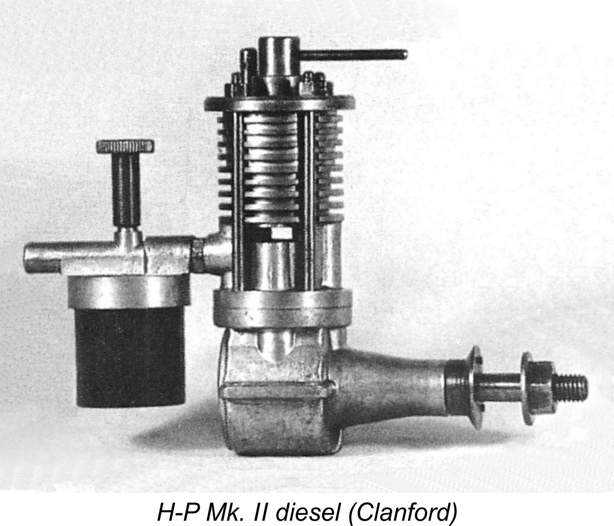
 It's worth noting that D. J. Laidlaw-Dickson went along with the previously-noted "Aeromodeller" advertisement by citing a displacement of 4 cc for the H-P entry in the table of British commercial diesels which formed part of his Spring 1948 article in "Model Mechanic" magazine to which reference was made earlier. He thus supported Clanford's displacement claim, although it's admittedly unclear which Mark of the engine he was talking about. As ever, the only way to resolve this question would be to take measurements from an actual example. If anyone reading this article has an H-P diesel having a precisely measured and confirmed displacement of 4 cc, I’d be immensely grateful to hear from you!!
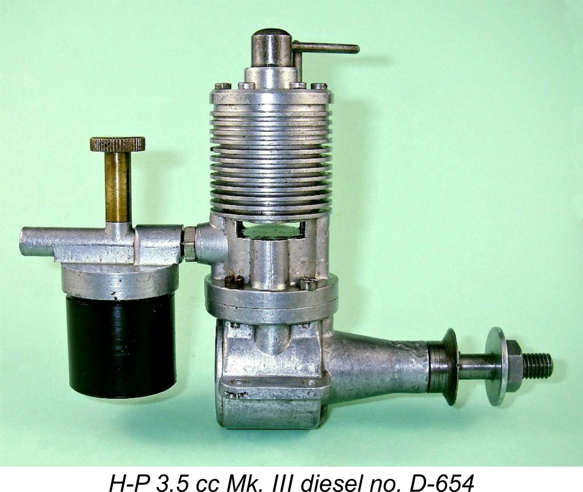 But now we get back (as ever) to the thorny issue of displacement. In this case, the factor that messes things up is my own illustrated engine number D-654. If measurements taken from this example confirmed the 4 cc displacement claimed by all of the above-noted sources, we’d be home and dry. The problem is that they don’t! Based upon precise and repeated measurements, it turns out a) that the claimed displacement is a considerable exaggeration, at least in this instance; and b) that this particular engine is slightly over-square – very unusual for a sideport diesel of the period in question, in which long-stroke geometry was generally favored.
 Warring stopped short of quoting a weight for this engine, thus reinforcing the impression that he probably never examined one personally. The illustrated example weighs a ponderous 8.08 ounces (229 gm) - considerably heavier than the contemporary
 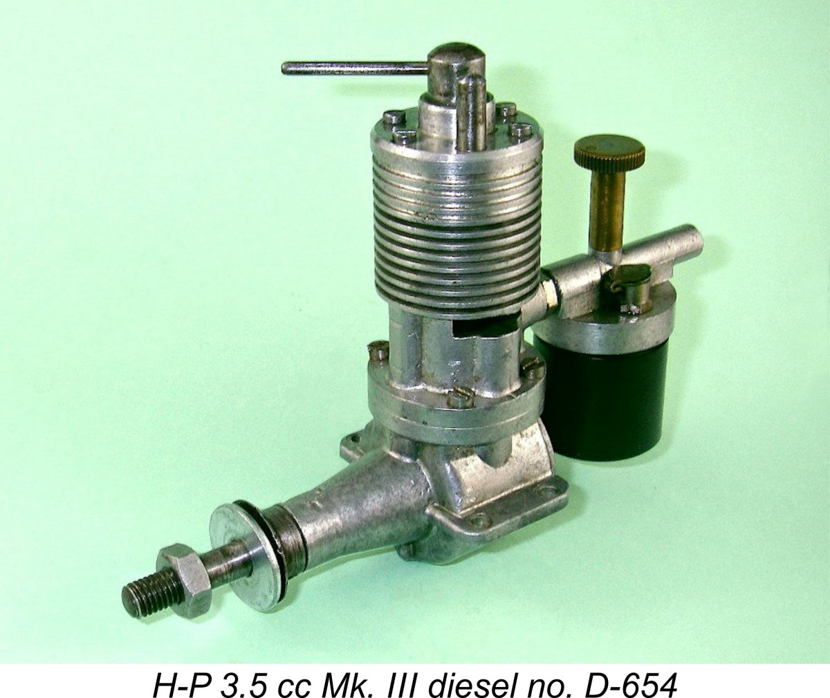 My illustrated example of this engine is in near-mint condition, seemingly having had little use, although it has clearly been mounted and run. This particular unit was given to the previous owner many years ago by one Terry Everit, who used to work part time at H-P in the late 1940’s. I am thus only the engine’s third owner in over 70 years!
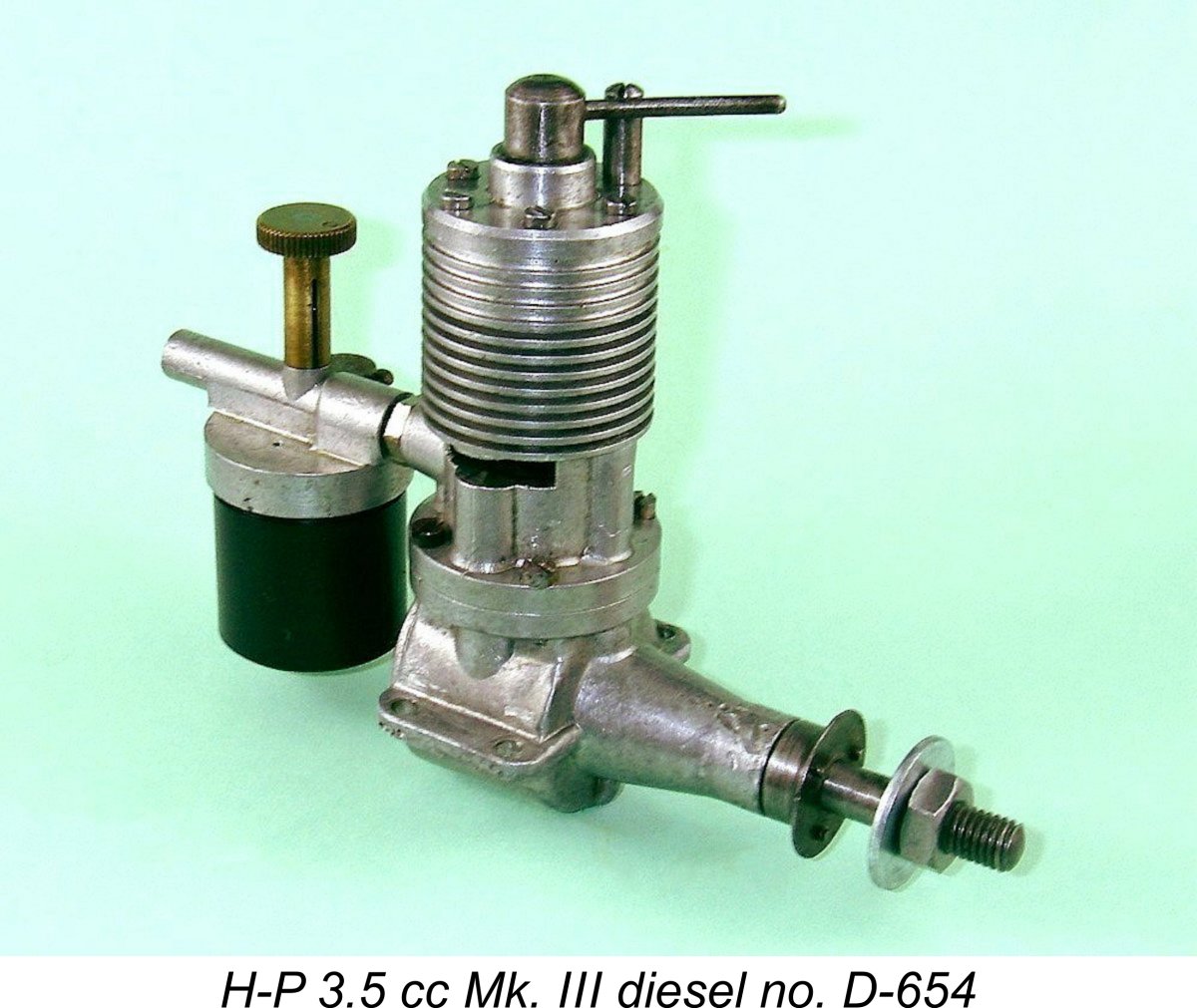 The H-P’s main external features are clearly visible in the attached images. As can be seen, the unit is built up around a main casting consisting of two separate components – the crankcase itself with its integrally-cast main bearing, and an upper cylinder casting which incorporates the bypass and exhaust porting, the inlet stub and the cooling fins above the exhaust port level. The upper and lower castings are united by an installation flange below exhaust port level, being secured by four machine screws.
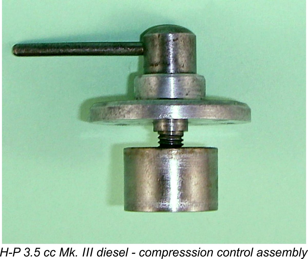 So how does this comp screw engage with the contra piston? Very simple – below its locating shoulder, the comp screw is externally threaded 2BA, but with a left-hand thread! This thread engages with a similar 2BA female left-hand thread formed in the centre of the contra piston. Hopefully a moment’s thought will convince the reader that the effect of turning the comp screw is not to change the elevation of the screw itself as in the usual case (since that is fixed), but to move the contra piston up or down due to the action of the comp screw’s threaded lower end on the internally-threaded hole in the centre of the contra-piston.
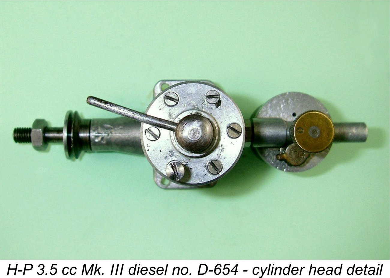 The final comment regarding the compression adjustment arrangements relates to the fasteners which secure the head in place. These have a very skinny thread of 8BA, the female threads for which are easily stripped if over-tightened – please take care!! Five of the six fasteners are conventional machine screws, but the sixth is a slot-headed steel stud with an 8BA spigot protruding from its base. The intent is clearly that after the required range of compression settings is established, the stud can be relocated to any of six available locations in order to limit the range of available compression settings. A good design, both to minimize the possibility of creating a hydraulic lock and to retain the correct starting and running compression range.
 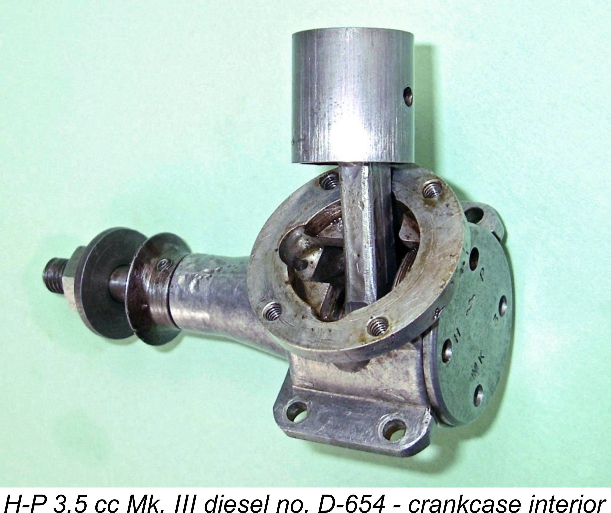 I was unable to fully dismantle the engine since the backplate appeared to be screwed home “for keeps”, resisting all my efforts to free it by fair means. However, I can report that the flat-topped cast iron piston is a relatively lightweight component having quite thin walls. I would actually have preferred to see a bit more metal left to form the bosses for the solid steel gudgeon (wrist) pin. The 0.125 in. (3.175 mm) pin looks to be very much on the skimpy side for a diesel engine of this displacement, although it too contributes to a lower-than-average reciprocating weight. It appears to be a press-fit in the very short bosses.
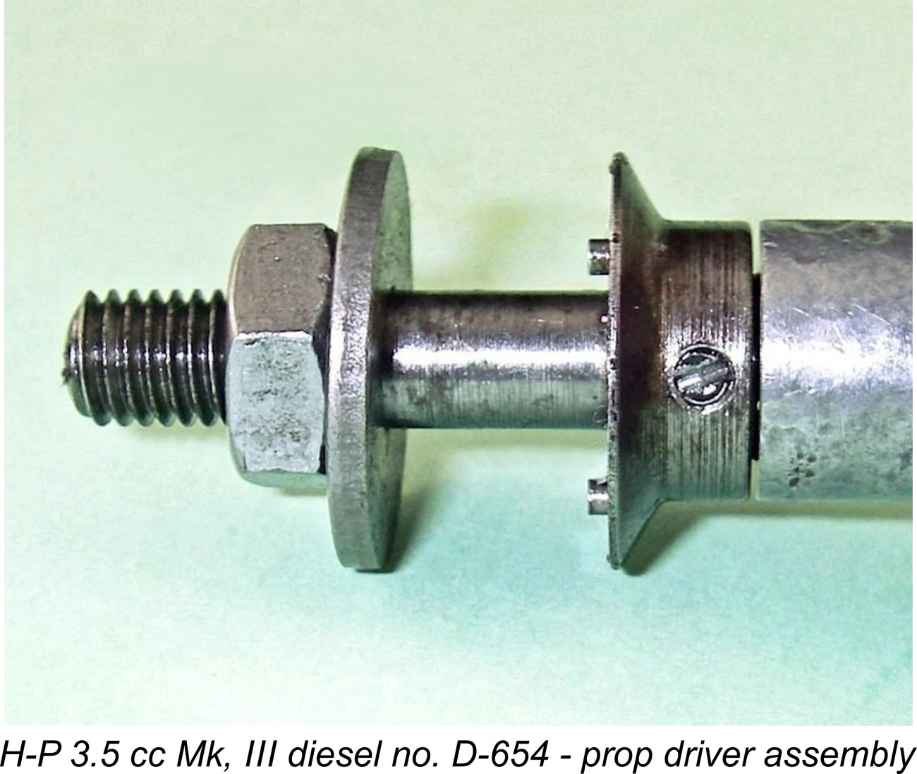
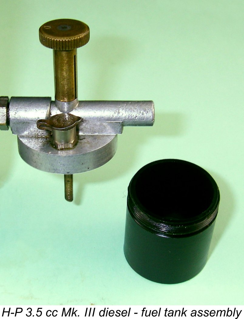
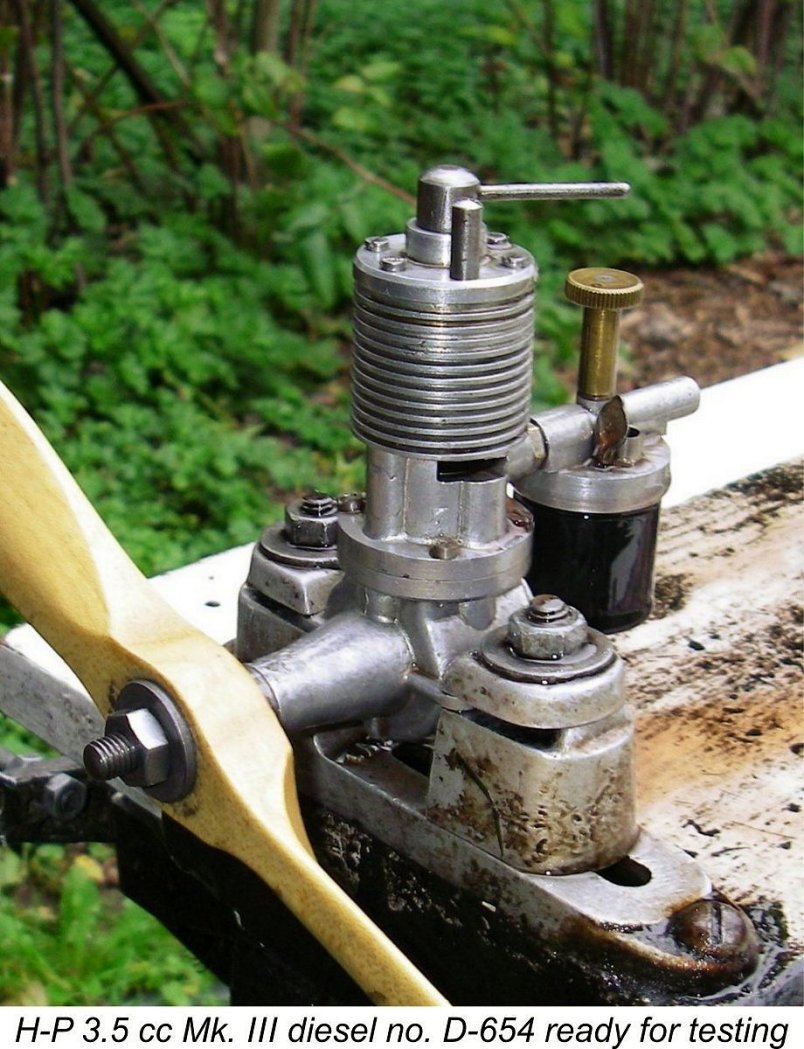 I’ve actually had this engine for quite a while, but had never got around to doing a full test due to the very loose contra-piston which was found to preclude the establishment and retention of stable compression settings. On its one previous running session in my hands, the engine had turned an 11x5 Taipan prop at 6,300 rpm. However, I was forced to maintain the compression setting by hand, making precise settings very difficult to establish and sustain while taking speed measurements. I felt at the time that the engine would probably do slightly better than this if provided with a better-fitting contra-piston. As related above, I made such a component prior to undertaking a full test of the engine.
 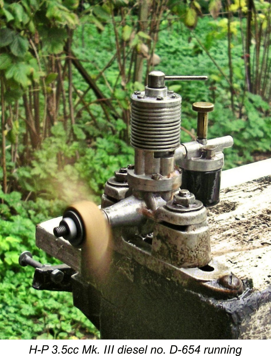 response to both controls. My replacement contra-piston proved to be perfectly fitted, holding its settings firmly while remaining readily adjustable at all times. The needle gave very positive feedback without being overly sensitive, making the optimum needle setting very easy to establish. The split thimble on the needle held its setting securely at all times.
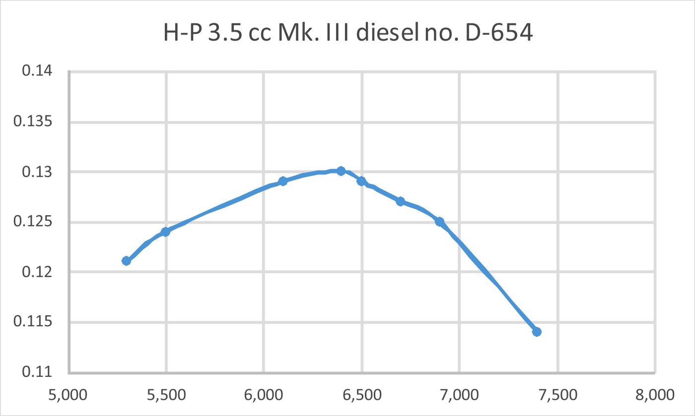
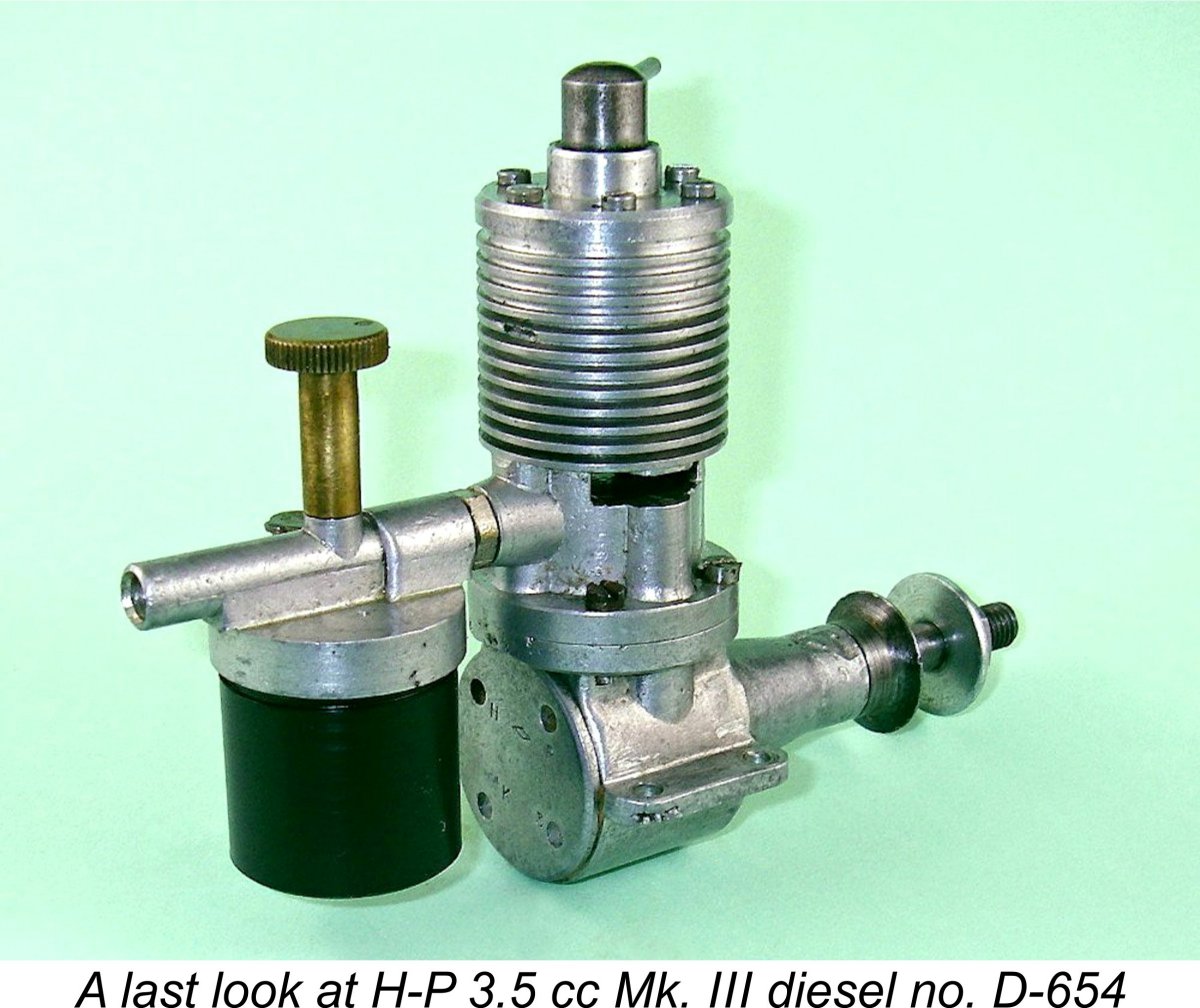 If my own tested example is any indication, the H-P range of model engines were products of a manufacturer who worked to very high standards and had a good grasp of model engine design as it existed in 1946-47. The downfall of the range almost certainly came about in large part because the company lacked either the resources or perhaps the incentive to develop the new updated models which would have been required for the range to remain competitive.
| |