
|
|
The Mechanair 5.9 cc Spark Ignition Engine
Before getting started on this review, I’d like to thank my good mate Maris Dislers of Glandore, South Australia, for his invaluable assistance in tracking down a number of key advertisements which proved to be crucial in establishing the production and marketing history of this engine. As a result of his efforts, a number of statements made by earlier commentators have been conclusively shown to be in error, or at least to require clarification. The correction of past misinformation must surely be one of the chief goals of any responsible historian. The present article is a case in point – it contradicts or at least clarifies a certain amount of what has been said in the past about the Mechanair 5.9 cc sparker, by Mike Clanford among others. However, it does so on the basis of persuasive evidence which I've openly shared with the reader.
I also make a serious effort to uncover and present all of the available information so that no-one has to go through this exercise again. The inevitable result of this approach is that my articles tend to be very long. This has led to periodic criticism to the effect that I include too much information. I make no apologies for this – everyone is free to read as much or as little of my articles as they choose. That’s what the “scroll down” control is for - please feel free to use it! Having got that off my chest, it’s time to set the stage for the telling of the Mechanair story. Background
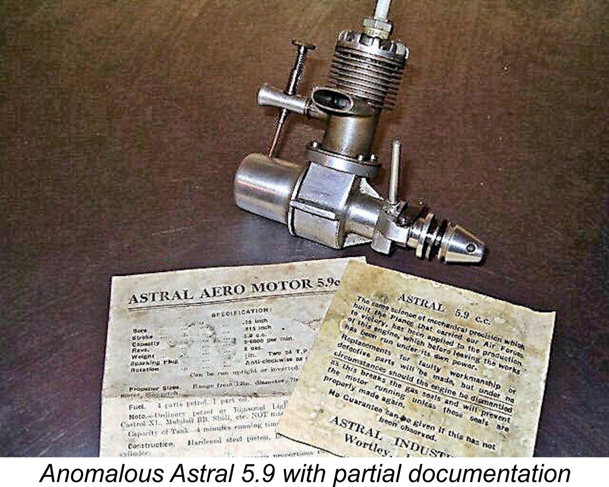
At the time when this article was originally published, I had seen no evidence to support the notion that the engine with which we are concerned here, or a predecessor, was ever manufactured in Leeds. However, things changed in that regard immediately after the article's first appearance on August 1st, 2019, when my good friend Ken Croft promptly sent me a couple of images in his possession which required a re-evaluation of this aspect of the story. Ken's images show what unquestionably seems to be a previously-unreported variant of the Astral/Mechanair 5.9 cc model. Although its crankcase, cylinder, timer and carburettor mounting arrangements seem to be identical to the corresponding features seen on the more familiar Mechanair 5.9 which forms my main subject here, it displays a number of key differences. Chief among these are the radially-finned cast alloy head, backplate-mounted fuel tank, very different venturi and needle valve and seemingly soldered-on exhaust stack. It also features an alloy spinner nut. The fuel supply arrangements on this engine represent one of the major differences between it and the "standard" Mechanair to be described below. The design eventually adopted (see below) was evidently prompted by the fact that it allowed the use of the tank with the engine inverted - a very popular orientation at the time. The earlier arrangement seen here made it impossible to use the back tank with the engine inverted. The subsequent improvement in mounting flexibility certainly suggests that the illustrated Astral unit preceded the standard Mechanair design. Ken did not have access to the actual engine shown in these images, nor had he ever seen an example of this model. Neither have I, for that matter - indeed, it does not appear in any of the standard reference works on British model engines (and I have 'em all!). It was also never advertised at any time. Ken received the images some years ago during the course of a discussion about Mechanair. Beyond what is visible in the photos, he has no information, nor does he know where the engine is today. Rather fortuitously, one of the two images includes portions of the documentation which evidently accompanied the engine. There's sufficient material displayed to confirm that the engine was called the Astral Aero Motor 5.9 cc and was apparently made or at least marketed by a firm calling itself Astral Industries of Wortley, a suburb of Leeds. The wording of the visible portions of the documents is identical to that later applied to the Birmingham-made Mechanair engines, of which much more below.
Before anyone gets too excited, it's important to recognize that this evidence does not confirm that the engine was actually manufactured in Leeds. As we shall see, beginning in mid 1946 the Astral Aero Model Co. marketed a somewhat modified version of this engine under the name of the Astral 5.9 cc model, although that variant appears to have been manufactured all along by Mechanair in Birmingham, who were also openly credited by Astral with the design. It's perfectly possible that Mechanair were also responsible for the newly-revealed variant as well - the fact that it was marketed by a different albeit seemingly related Astral company does not preclude this. The fact that Astral later cited Mechanair as the "developers" of the engine appears to add considerable weight to this possibility. Of course, it remains possible that this variant was in fact manufactured in Leeds by an offshoot firm established by Astral to engage in the model engine manufacturing business. However, why then would Astral later credit Mechanair with the development and manufacture of a design which they had previously developed in large part themselves? Also, after going to the considerable trouble and expense of setting up a precision engineering manufacturing workshop in Leeds, why would they abandon that effort after making at most a mere handful of engines? If the engine was in fact manufactured for a time in Leeds, that phase didn't last long and very few examples must have been produced there - the illustrated example is the only one that I have ever seen, even as an image. I personally think that it's far more likely that this variant was a Birmingham-built prototype of a design by Mechanair which Astral intended to market under the name of an offshoot company, Astral Industries. This would explain both its extreme rarity and the fact that the later examples underwent some modification - that's what happens to prototypes! Whatever the truth, by mid 1946 a somewhat modified version of the engine was unquestionably being manufactured by Mechanair, who were openly credited by Astral with the development and production of the engine. In the absence of any additional evidence, we have to leave the significance of this previously unreported variant and the possibility of its manufacture in Leeds as open questions. Once we get to the more familiar version of our subject motor, things become greatly clarified. A close consideration of the evidence makes it appear almost certain that this version of the engine was built to essentially the same design throughout (with periodic minor variations) and was designed and manufactured all along by Mechanair Ltd. of Warwick Road in Birmingham. The Astral Aero Model Co. merely acted as the marketing agents for the engine until December 1946 under an arrangement whereby they applied their own company name to an engine made by others. From the time when Astral Aero Model Co. openly entered the picture in mid 1946, we're talking about the same engine throughout, with minor variations. There's persuasive evidence to confirm that model engine manufacture was by no means the sole activity conducted by Mechanair Ltd. during the early post-WW2 period. Indeed, it's almost certain that it wasn't the firm's major activity - the model engine venture may well have been a sideline conducted as a "labour of love" at the instigation of a model enthusiast associated with the company management. The firm's main business seems to have been the manufacture of small portable air compressors for automotive or industrial use, an activity which continued well after the termination of Mechanair model engine production (see below). The company name is completely consistent with that product line, makng it appear not unlikely that air compressor manufacture was Mechanair's main business throughout. It's worth citing several pieces of evidence to support the above statements. An invoice dated November 30th, 1949 which is preserved in the records of the Sheffield Industrial Museums Trust confirms that Mechanair was still very much active in the compressor business as of that date and still located on Warwick Road. In addition, a poster on a forum dedicated to UK stationary engines reported owning a vintage Mechanair compressor of unspecified date which was powered by a small Villiers engine. I can find no evidence regarding the date on which the company first embarked upon this line of business, nor is it clear when operations were terminated beyond the established fact that Mechanair was still trading in 1951 (see below). The other major participants in our story, the Astral Aero Model Company, had entered the kit market in 1939 – a classic case of poor timing given the highly inconvenient September 1939 commencement of WW2. However, the company somehow survived the war years by offering kits of a variety of notable The company was sufficiently successful that for some years it was able to maintain a showroom at 245 Regent Street in London. However, it evidently either fell on hard times or was bought out by a competitor, since the final Astral advertisement that my good mate Maris Dislers was able to find in his extensive magazine collection was dated February 1949. The Astral company added a 5.9 cc spark ignition engine to its overall range in the first half of 1946, marketing it as the Astral 5.9 cc model. It was among the first wave of new British model engine designs to reach the market within the first year following the conclusion of WW2, but turned out to be the only model engine ever offered under the Astral name. Interestingly enough, they never appear to have advertised the previously-mentioned variant in Ken Croft's images at any time, reinforcing the notion that it may well have been a prototype.
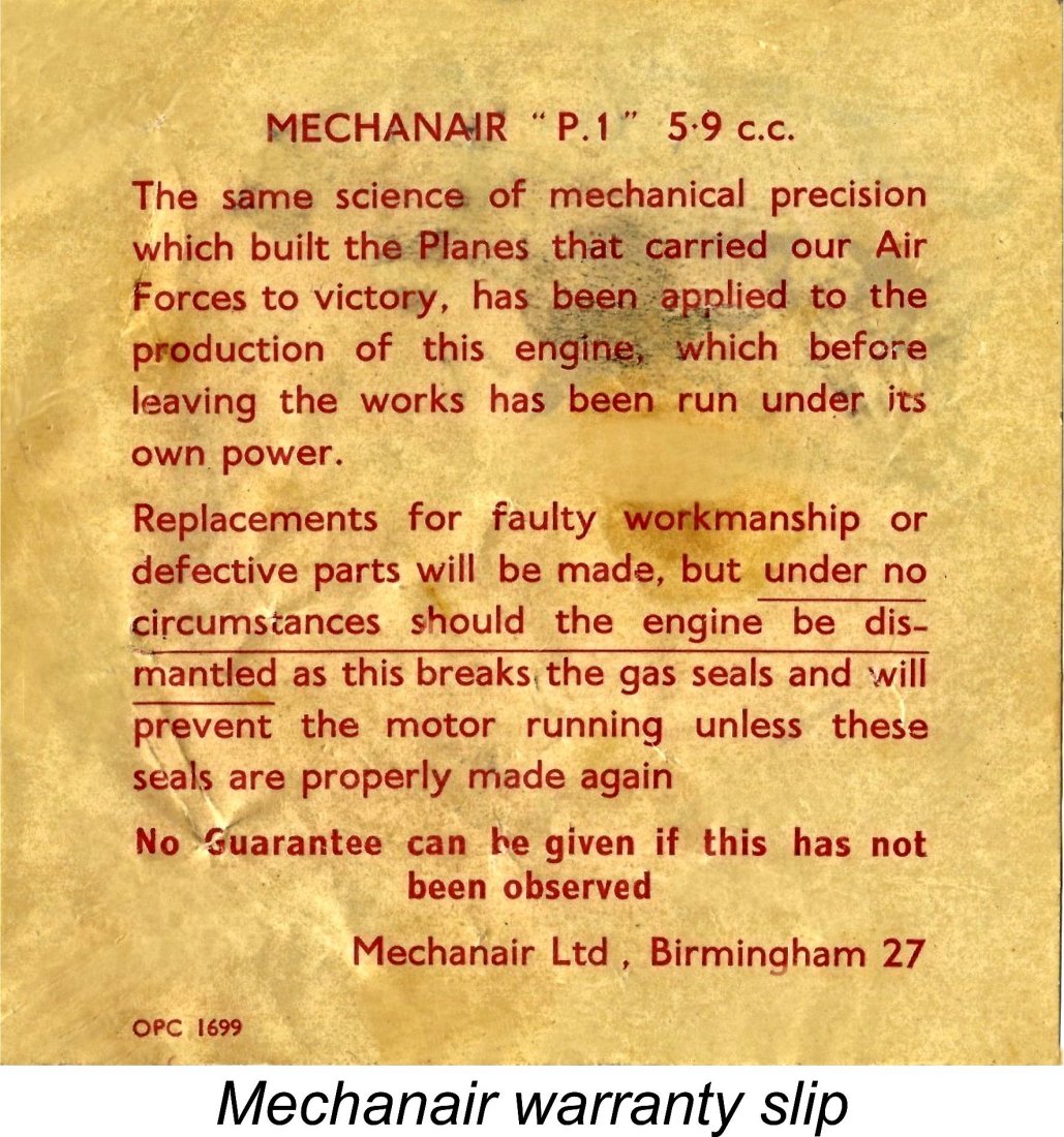
As discussed earlier, many previous commentators appear to have assumed that the Astral model was originally manufactured in Leeds by Astral themselves. In fact, a closer examination of the available In reality, the evidence appears to confirm that Mechanair Ltd. of Warwick Road, Birmingham 27 (the address given on the back cover of the engine's instruction sheet) had been the developers and actual manufacturers of the Astral 5.9 sparker all along, with Astral merely acting as their main marketing agents up to December 1946. There's no doubt at all that Astral themselves openly credited Mechanair with the development of the engine. The question of whether Astral approached Mechanair to request that they develop the engine or whether Mechanair first developed their design and then went looking for a marketing partner cannot now be authoritatively resolved. That said, the latter of these two possibilities actually seems to me to be more likely. The statement on the engine's guarantee slip that "the same science of mechanical precision which built the planes that carried our Air Forces to victory has been applied to the production of this engine" appears at first sight to imply that Mechanair had been involved in wartime precision engineering activities relating to aircraft production. The characterization of the manufacturers as a "famous firm of aero engine manufacturers" in the December 1946 advertisement reproduced above specifically suggests an involvement of some kind with aero engines, possibly as specialist component suppliers. Such activities would most likely have been terminated following the conclusion of In my personal opinion, the idea that Mechanair was involved from the outset is pretty much confirmed by the wording of the previously-cited Astral advertisements. First, there’s the comment which appeared in the July 1946 advertisement to the effect that the engine had been “developed for us (Astral) by a leading firm of engineers”. The use of the expression “for us” rather than “by us” clearly implies that this was in fact an outside job from the get-go. At the very least, it confirms beyond doubt that an engineering company other than Astral was heavily involved from the outset. To further reinforce this impression, the December 1946 advertisement reproduced above includes the statement that the engine was “produced for “ASTRAL” by the famous firm of Aero Engine Manufacturers: MECHANAIR LTD.”. Evidently Felix had escaped from the proverbial bag!! It appears very likely on the basis of this evidence that Astral had never at any time manufactured the engine and that Mechanair had been responsible for its development and production all along. This clarification led to the engine being briefly referred to as the “Astral Mechanair”, but very soon thereafter Astral evidently withdrew from their marketing agreement with Mechanair, taking their company name with them.
There's also some purely anecdotal evidence to the effect that a firm called the Model Aerodrome of 141 Stratford Road in Birmingham also marketed the engine for a time, but I have been unable to uncover any firm evidence to support this contention. All that I can say is that the Model Aerodrome was unquestionably responsible for the marketing of Britain's sole entry into the slag engine sweepstakes, the infamous Drome Demon of 1946. The key point here is that Mechanair had clearly moved rapidly to make arrangements for their engine to be marketed by a different firm or firms once Astral withdrew. Moreover, they were continuing to market essentially the same design as opposed to a revised version of an earlier Astral model, as suggested by some previous commentators. This phase of the engine’s marketing had unquestionably begun by February 1947, since as of that month we find the Mechanair being offered under that name by the famous firm of Gamages Ltd. in London - no mention of Astral. The relevant advertisement is reproduced above at the right. Interestingly enough, the engine was now offered by the name “Mechanair P1 5.9 cc petrol aero engine”. The P1 designation was never applied to the engine by Astral, being solely a Mechanair designation. This seems to imply that it was the company’s first petrol engine and that further models might have been in contemplation. The listed price of the engine was 8 guineas (£8 8s 0d - £8.40) – a relatively high price by the standards of the day, but not without parallel at that time. What kind of engine did buyers get for their substantial outlay?!? Let's find out! Description
In the table, bore and stroke measurements of both Mechanair models were given as 0.75 in. (19.05 mm) apiece. The problem is that these measurements yield a calculated displacement of only 5.43 cc (0.331 cuin.) as opposed to the engine’s cited nominal figure of 5.9 cc (0.360 cuin.). Even more oddly, the actual displacement of 5.9 cc is quoted correctly! The bore/stroke and displacement figures quoted by Warring cannot be reconciled.
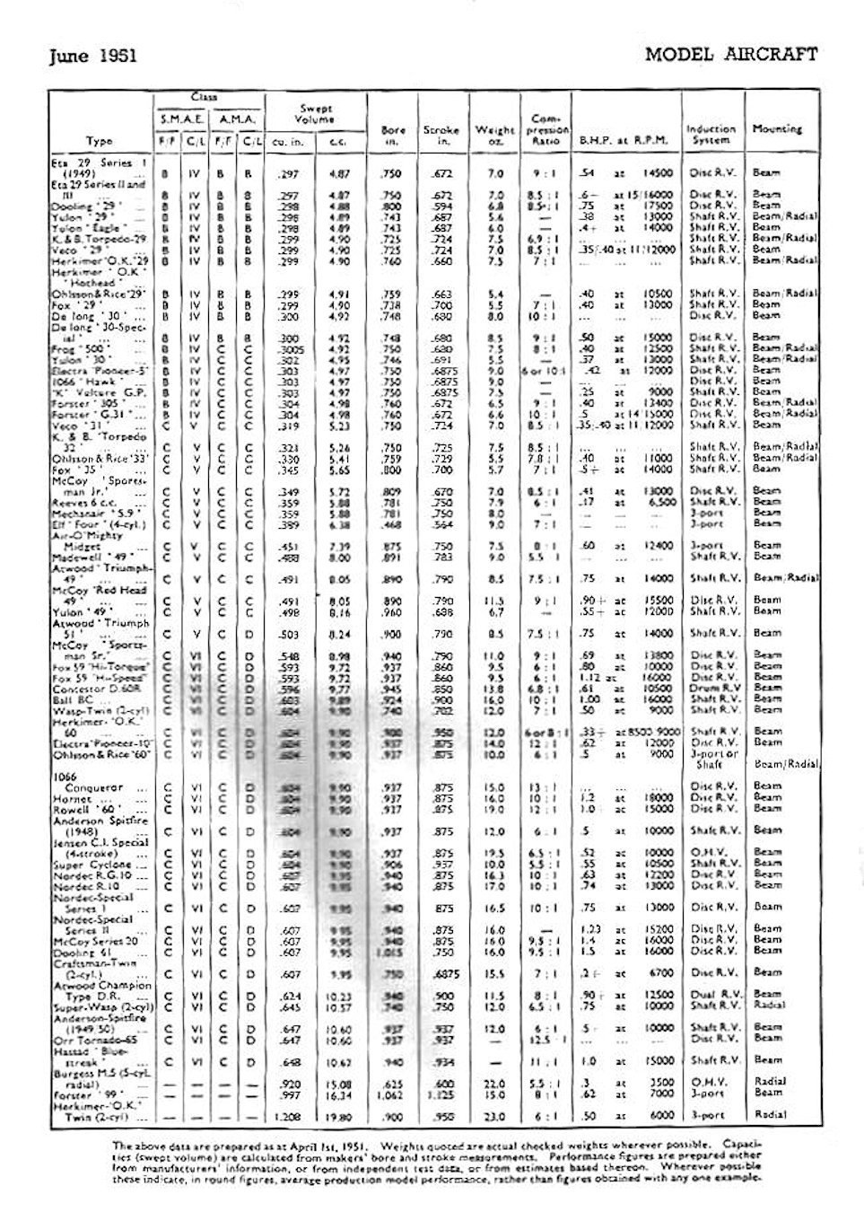
Even the normally reliable Peter Chinn got it wrong - in his table of spark ignition and glow-plug motors for 1948/1951 which appeared in the June 1951 issue of "Model Aircraft" and is reproduced at the right, he quoted bore and stroke figures of 0.781 in. and 0.750 in. respectively for the Mechanair. While these figures do yield the claimed displacement of 0.359 cuin. (5.89 cc) and the same stroke is cited by both Warring and Chinn, the bore quoted by Chinn differs significantly from that cited by Warring. In cases such as this where normally well-informed contemporary commentators present conflicting data, it seems best to give the deciding vote to the engines themselves. Carefully-taken direct measurements of my own three examples confirm that Warring's nominal ¾ in. (19.05 mm) bore dimension is correct, putting Chinn's figure in error. However, both writers have the stroke wrong! The nominal stroke of the engine is actually 13/16 in. (0.812 in. – 20.63 mm), which yields a calculated displacement of 5.89 cc (0.359 cuin.), exactly as advertised. This was an era during which British precision engineers preferred to work in fractions of an inch rather than decimal dimensions - the reasons for this escape me given their concurrent adherence to expressing displacements in cubic centimetres (cc), but there it is......... Interestingly enough, the previously-cited Gamages advertisement of February 1947 confirmed my measurements. The advertisement actually gave the stroke as being fractionally over my measured figure at 0.815 in., but this still reflects a nominal design figure of 13/16 in., allowing for "lathe operator's license". Presumably Gamages measured an actual example, something which neither Warring nor Chinn appear to have done (nor was Warring particularly careful about his displacement calculations!). Admittedly a rather inconsequential error, but we may as well get it right for the record! My illustrated test example of the Astral/Mechanair 5.9 cc unit weighs in at 251 gm (8.85 oz.) minus plug and 260 gm (9.20 oz.) with plug. Warring cited weights of 8.5 ounces (241 gm) and 7.75 ounces (220 gm) respectively for the two Mechanair models – with or without plugs is not made clear. Chinn splits the difference, quoting a weight figure of 8.0 ounces. Volumetrically-measured compression ratio is 6.75:1, a fairly typical and perfectly adequate figure for a non-racing spark ignition engine of the era. An 11x6 airscrew was recommended for free flight, with a 10x8 suggested for control line service. These seem to be quite reasonable recommendations.
The engine was built around a well-executed gravity die-cast crankcase which incorporated the main bearing housing in unit. This component’s chief failing was the rather skinny profile of the mounting lugs, which reputedly acquired an unsavoury reputation for breaking in a hard crash. This was actually a surprisingly common failing among early post-WW2 British engines – the need to build crash-resistance into mounting lugs had yet to be widely appreciated. Evidently a significant number of manufacturers had more confidence in the flying abilities of their customers than actual performances in the field would imply to be justified! The thin-walled steel cylinder featured integrally-machined cooling fins and was topped by a die-cast light alloy head which was secured with six slot-head machine screws. The head was centrally tapped to accommodate a 3/8–24 UNF spark plug. Almost all examples of the Mechanair which I have seen either in photographs or in the metal have been fitted with British-made Pacy spark plugs, making it appear likely that this was standard equipment as supplied. On this model, the head was not given any colour treatment, being left in its as-cast finish. The cylinder was secured at its base to the upper crankcase using four Allen-head machine screws. The engine utilized cross-flow loop scavenging with a lapped cast iron baffle piston. This piston was an extremely close fit in the bore - in fact, I would have said that it was if anything unnecessarily tight by spark ignition standards. A poster on one of the modelling forums stated that he had once purchased a new Mechanair Red-Head (see below) which had red running-in compound in its cylinder as received ex works. Evidently the company was aware that the piston/cylinder fit required a little freeing-up through the break-in process! A single rectangular transfer port was supplied with mixture through a bypass which was created by soldering a channel onto the transfer side of the lower cylinder. A pair of oval exhaust ports were placed on the opposite side of the cylinder. No exhaust stack was fitted.
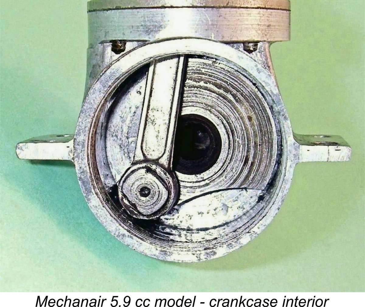
The gudgeon (wrist) pin was mounted inside the piston in an internal light alloy carrier, ensuring that the ends of the pin did not penetrate the piston walls. The design also minimized piston weight while at the same time reducing crankcase volume for better pumping efficiency. A single centrally-located Allen-head screw held the carrier assembly in place – the head of the screw is clearly visible through the exhaust ports protruding from the centre of the piston crown. The conrod was a sturdy-looking light alloy forging having an I-section column. The big end drove the crankshaft through a screw-in crankpin having a left-hand thread, as I was able to confirm later (see below). The steel crankshaft was hollow, presumably both for lightness and to promote better lubrication of the bearing, with a heavily counterbalanced crankweb.
When describing a spark ignition engine, an important additional parameter which needs to be quantified is the dwell period provided by the engine’s timer. This is the angle of crankshaft rotation during which the points are closed and hence in direct electrical contact with each other, thus supplying current to the coil's primary circuit. For a full discussion of this design parameter, see my separate article on spark ignition engine operation. For now, the important thing to understand is the fact that sufficient real time must be provided during each revolution to ensure full electro-magnetic saturation of the primary coil winding and its associated magnetic field before the points open to trigger the spark. The dwell requirement varies from engine to engine, the main factor being operating speed. A slow-speed unit like a Brown Junior, Atom .099, Bunch, Elf or even an early Ohlsson can operate successfully with a relatively short dwell period of 50 – 60 degrees or even less. A short dwell period both conserves the life of the flight batteries and reduces thermal stress on the coil, since it minimizes the proportion of running time during which the points are closed and current is flowing to the coil from the batteries. However, it also makes the engine more susceptible to ignition problems caused by point "float" - an inertia-induced delay in the points following the cam surface during the closing phase, resulting in a reduction of the effective dwell period. In addition, it limits the maximum speed at which the engine can be run because at higher speeds there's insufficient real time for the coil to become electro-magnetically saturated, as it needs to be to provide a good hot spark. This causes a misfire to creep in which cannot be eliminated using the controls, since the timer has now in effect become a rev limiter. In the case of the Mechanair, direct measurement confirms that the dwell period provided by the timer is of the order of only 40 degrees. Such an unusually short dwell period suggests that the engine was not expected to operate at high speeds. As we shall see below, testing proves this suggestion to be well grounded. Of course, since a short dwell period means that flight battery life should be well conserved, the use of the shortest dwell period that will work at the engine's design operating speed is well warranted. The tension of the flat leaf spring system that closes the points is relatively high, meaning that float should not be an issue at the kind of speeds for which the engine seems to have been designed.
At the rear, induction was provided for by a soldered-on spigot which accommodated the separate carburettor assembly. On the majority of examples, a split spigot was used. The delivery end of the venturi simply plugged into the unthreaded spigot, which was then tightened across the split using a sturdy wire collar around the outside of the spigot. The intention seems to have been to build some "give" into the assembly to minimize the possibility of impact damage. It also facilitated the re-orientation of the tank to accomodate inverted mounting, as depicted in the original Astral promotional images. Just to complicate matters, my own illustrated test example features what appears to be an original arrangement which is somewhat different and certainly far more secure. The spigot seems to have started life with the usual split, but this was not utilized. Instead, the spigot has been cleanly shortened and a separate externally Based on my long experience of such matters, I’d objectively say that this bears absolutely no evidence of being an owner repair – I’ve seen (and carried out) far too many of those to be easily fooled. This arrangement has been far too neatly and “invisibly” implemented. The very tidy soldering of the extension appears to be homogeneous with that of the main spigot to the cylinder. Indeed, it’s difficult to see how the additional soldering could have been carried out without disturbing the original spigot attachment unless it was carried out using the original jig to hold things in place. The clincher is the fact that the nickel plating of the cylinder extends to the entire spigot/extension combination. If this is a repair, it’s undoubtedly a factory job, since the nickel plating was applied after the repair was made. How many modellers have access to nickel plating equipment?!? Put another way, how many owners would bother with such a refinement? Finally, the fact that the engine appears to be virtually unused implies that this was indeed the original arrangement as supplied, since the unit appears to have had little or no opportunity to become damaged in the first place.
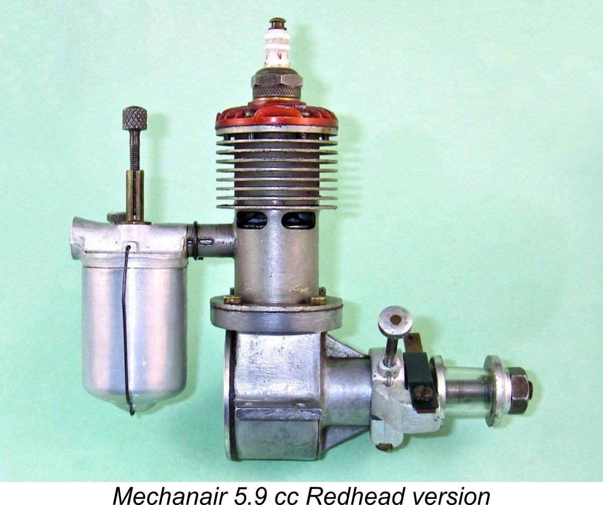
The die-cast intake venturi incorporated the tank top in unit. The externally-threaded needle engaged with a brass split carrier which was mounted on the top of the venturi. The tapered end of the needle crossed the venturi throat to engage with a surface fuel supply orifice on the opposite side of the intake. A brass venturi insert was held in the venturi throat by the needle, allowing for adjustment of the venturi throat diameter. The alloy fuel tank was held in position by a wire hanger. The engine was completed by a screw-in backplate which was configured to engage with a suitable pin spanner for assembly and removal. If you really must remove the backplate "just for a look", please use such a tool! Far too many fine old engines become irretrievably marred through the use of inappropriate tools.
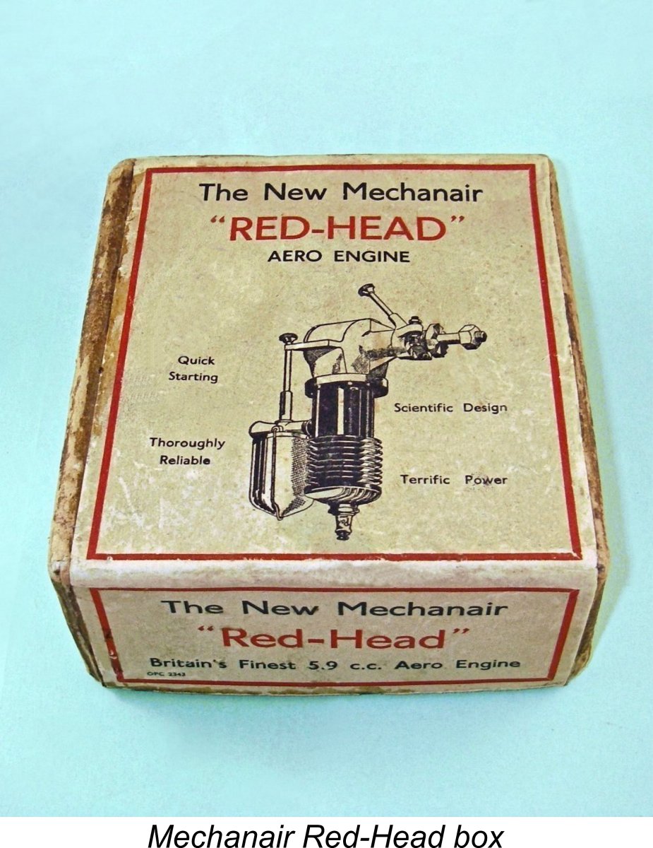
The final version of the engine was the Mechanair "Red-Head", so named because of its red-anodized cylinder head. The literature with my New-In-Box example still refers to the engine as the Mechanair P1 model, but there's no mention of the P1 designation on the box label. Instead, the engine is referred to on the label as "The New Mechanair "Red-Head" model. This implies that it was seen by the manufacturers as a distinct design. Considerations of economy may have dictated the ongoing use of the literature associated with the earlier P1 model - there are many precedents for such an approach.
This of course does not preclude the possibility of internal changes having been incorporated. Indeed, it seems probable that some internal changes were implemented, since my examples of the Red-Head both tip the scales at 273 gm with plug, some 13 gm more than my earlier plain-head P1 version. This is in direct contradiction to Ron Warring's Appendix II table, which claimed a somewhat lower weight for the Red-Head version of the Mechanair. As stated earlier, most examples of the engine were manufactured to accommodate a 3/8-24 UNF spark plug. However, the last 200 or so examples which were manufactured were reportedly tapped to accept the ¼-32 UNEF plugs which were then (1948) becoming the accepted standard. Warring’s previously-cited Appendix II table indicates that both versions of the Mechanair sold for the relatively high price of £8 8s 0d (£8.40), including coil and condenser. We saw earlier that the engine was being offered at this price by Gamages as of February 1947. This figure was equivalent to the before-tax weekly income of a relatively well-paid individual in Britain at the time.
It’s difficult to get a really good estimate of production figures because the engines never appear to have carried serial numbers. All that can be said is that the Astral 5.9 was on offer by that name for some 7 or 8 months from the first half of 1946 up to December of the same year. Thereafter, the successive P1 and Red-Head versions of the same engine (with minor variations) seem to have remained on offer by the Mechanair company under its own name until early to mid 1948, at which time the rising diesel tide then inundating the British modelling scene swept the engine aside along with the majority of other British general purpose spark ignition units.
Whether or not series production was terminated in 1948, as I personally believe, it's a seldom-noted fact that the end of series production was by no means the end of the Mechanair story! It appears that after series production ceased, the company found itself holding considerable stocks of unused parts for the engine. During the early 1950's the firm conceived the idea of recovering at least part of the capital which these components represented by selling them off as kits for completion by purchasers. The attached advertisement from the March 1951 issue of "Aeromodeller" magazine exemplifies this effort - the exact same advertisement was repeated in the April 1951 issue.
The best estimates that have been put forward to date suggest that perhaps 700 or so examples of all versions of the Mechanair were produced between 1946 and 1948 – a production period of around 2 years, give or take. Given the clear evidence that Mechanair was turning out a range of high-quality precision products, with the Mechanair 5.9 undoubtedly being merely one product among others, this estimate of an average of around 30 units monthly appears to be entirely credible. The monthly figure was doubtless considerably higher during the first six months or so prior to the progressive emergence of diesel dominance in Britain, tailing off thereafter until production ceased, probably in early to mid 1948. The estimated total is certainly consistent with the fact that although the engine is not all that commonly encountered today, it doesn’t quite qualify for the “unobtanium” title. The number of engines completed from the later kits is of course unknown, but there were probably a few. Based upon an examination of my own three examples, it’s readily apparent that these engines were built to the very highest standards by an extremely capable manufacturer. All key fits and finishes in my examples are exceptionally good - up to the best "model engineering" standards, in fact. The engines appear well able to give long and dependable service. The Mechanair 5.9 cc Sparker on Test Consideration of the Mechanair's very high quality of construction together with its main design features would lead one to expect it to be a dependable performer, albeit at relatively modest speeds. Indeed, it is generally characterized by those having operating experience as a very dependable and user-friendly engine indeed. Not a great deal of power by all accounts, but an easy-starting and sweet-running unit which clearly endears itself to its owners. Anyone wishing to see video footage of a Mechanair being started can do so through this link. It so happened that at the time when I arrived at the testing stage of my research on the Mechanair, I had been working on a completely separate "how to" article about the operation of spark ignition engines in general. In connection with that article, I had constructed a state-of-the-art transistor-switched spark ignition support system for use in bench testing classic sparkers. This system uses the engine's timer to trigger a switching transistor which controls the current in the primary circuit, thus taking most of the electrical load off the points (although they remain a functional part of the overall system). I had proved the efficiency of this system by running a very successful test of a 1946 Queen Bee sparkie, as reported elsewhere. A number of other spark ignition units had subsequently been successfully run. Now it was the turn of the Mechanair. The test example had clearly been mounted and run in the past, although it appeared to be little used, seemingly remaining in fine mechanical condition. In fact, it felt relatively stiff to me - the piston/cylinder fit was still very much on the tight side, implying that the engine was by no means fully run in. In addition, the drag produced by the timer seemed somewhat higher than usual, due presumably to the combination of a relatively large-diameter cam and a very strong spring closing the points. I began by putting the Mechanair through the full series of ignition system checks which are described in detail in my separate article on spark ignition operation. It passed all of these checks with flying colours, confirming that it was all ready to run. Bearing in mind the maker's recommendation of an 11x6 prop for free flight work, I elected to begin with a grey Taipan reinforced nylon 11x5 airscrew. This hefty prop provides a very strong flywheel effect, which is often an aid to achieving initial starts with an unfamiliar engine. It should also more or less duplicate airborne rpm for the recommended 11x6 prop.
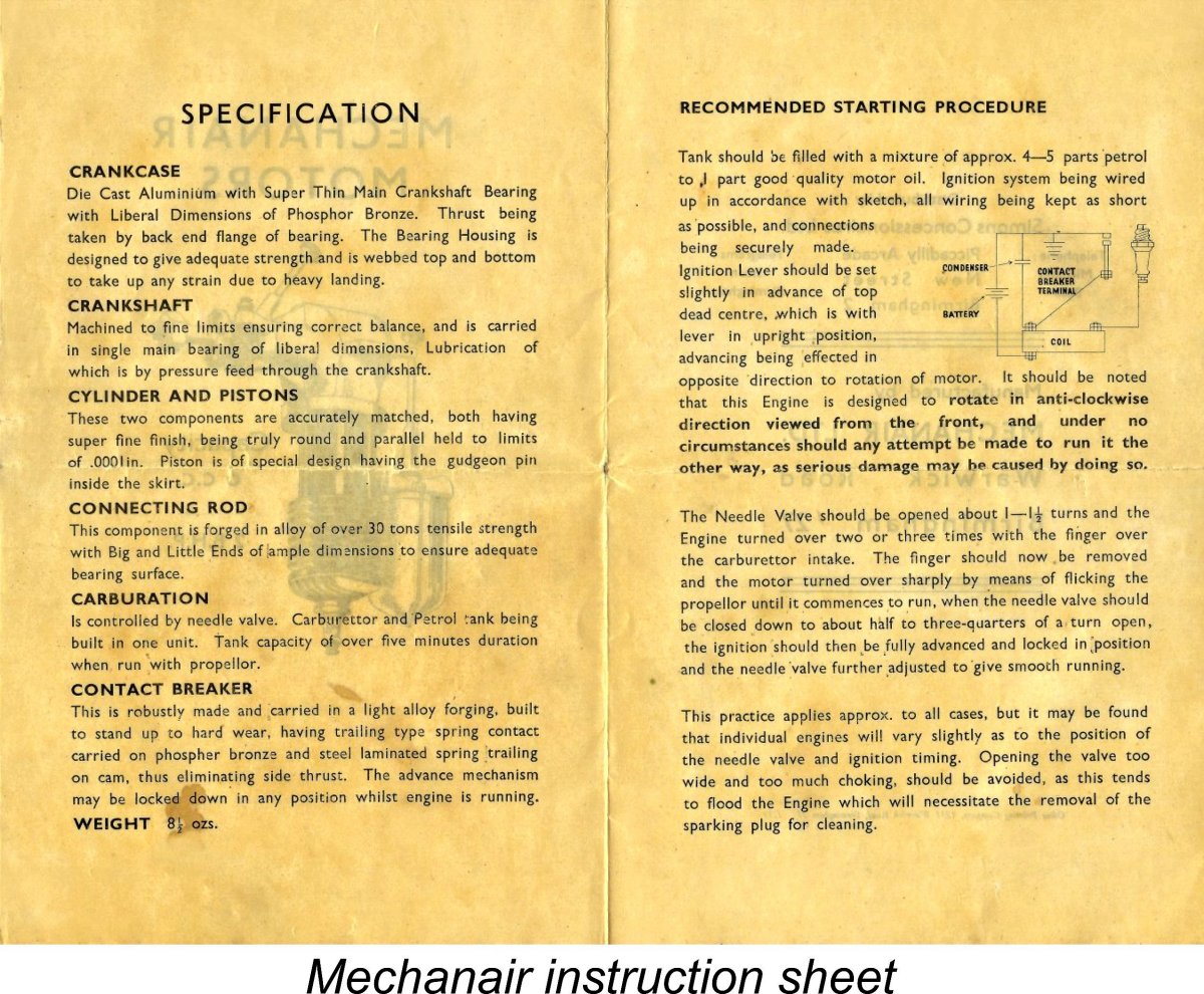
I used the same batch of fuel on which the Queen Bee and others had run so well, namely a mixture of 3 parts of Coleman camp fuel (white gas) to 1 part of SAE 60 mineral oil (castor oil doesn't mix with gasoline). The makers of the Mechanair actually recommended 4-5 parts of petrol (gasoline) to 1 part of "good quality motor oil" of unspecified viscosity, but I was taking no chances with the engine's finely-finished bearing surfaces, hence my use of a 3 to 1 mix. The manufacturer's instruction sheet suggested a needle valve seetting of around 1 - 1½ turns open for starting. I decided to adopt the higher of these suggestions - within limits, better too rich than too lean. As things turned out, this was a very poor decision! The instructions also recommended that once the tank was filled and the needle set, the only preliminary to starting should be two or three choked turns of the prop (with the ignition switched off). Thanks to the relatively low explosive limits of gasoline (the range of percentages of gasoline vapor in air which will ignite), only a very small amount of gasoline vapour is required in the cylinder to achieve a start. This means that an exhaust prime should never be necessary. As a general rule, this is true of all spark ignition engines, although there are certainly exceptions. I adopted the role of a new Mechanair owner back in the day by following the manufacturer's instructions to the letter. After ensuring that all ignition connections were secure, I set the timer at the pre-determined starting position in which the points opened just prior to top dead centre, filled the tank, opened the needle 1½ turns, administered three choked turns of the prop, switched on the ignition system, and I was all set! Or so I thought .......the first problem encountered was a marked tendency for the prop to become loose during flicking. The previously-mentioned absence of any taper or other means to secure the prop driver required that the prop be really well tightened down. When doing this, there was a tendency for the shaft to turn with the nut, which therefore did not turn on its threads to tighten its grip. I got around this by inserting an Allen key in the set-screw for the timer cam and using this to prevent the shaft from turning while the nut was tightened. This proved to be quite effective, allowing the prop to be mounted very securely.
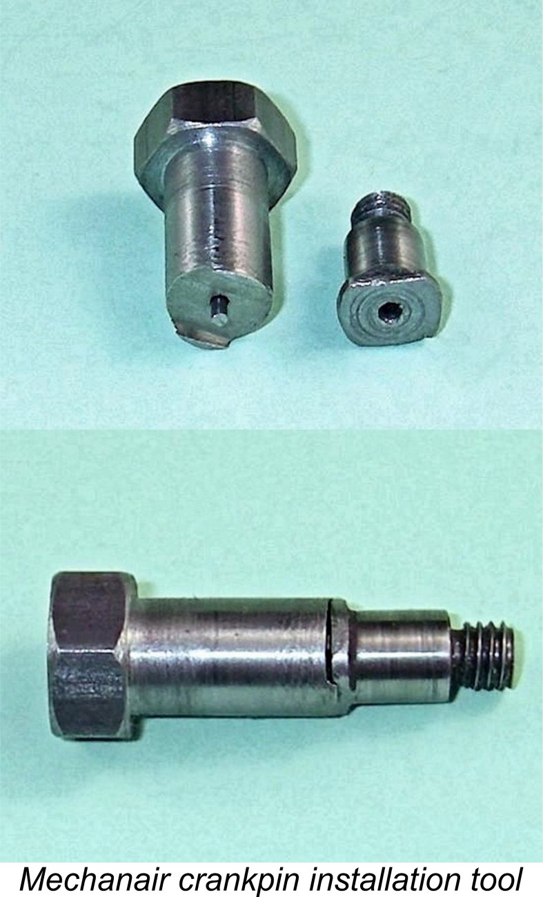
It turned out that this was a rather fortuitous occurrence, since it not only revealed a potentially serious developing fault but also clarified a construction detail regarding which I had previously been uncertain. It turned out that the crankpin is indeed a screw-in component, as surmised earlier. Moreover, it has a left-hand thread, as it needs to have in order for operating drag to tend to tighten it while the engine is running in the "normal" direction. This completely explains the otherwise odd comment in the instruction sheet that "This engine is designed to rotate in anti-clockwise direction, viewed from the front, and under no circumstances should any attempt be made to run it the other way, as serious damage may be caused by doing so". Reverse operation would doubtless have the effect of unscrewing the crankpin in very short order, with serious consequences indeed.
Regardless of the cause, this threw everything out of alignment, completely explaining the symptoms that I had been detecting. Thankfully, no permanent damage seemed to have been done beyond some scuffing of the internal backplate surface, so I was able to re-tighten the offending part very securely. Doing so required me to make a special tool as illustrated here. A tool of this kind must have been used in the original assembly of the engine - the crankpin has to be installed after the rod is in position, and there's no space to deploy a normal wrench of any sort. This could well explain the failure of our unknown previous owner to tighten the crankpin properly - without that special tool, it simply can't be done. That said, when the engine runs in the correct direction, the inevitable torque applied to the crankpin by its rotation within the conrod big end bearing should have the effect of further tightening the crankpin in its left-hand thread. This makes it seem pretty clear that this example the engine had never been run after being disturbed. It's worth mentioning in passing that this assembly seems to me to argue fairly strongly against operating this engine on glow-plug ignition. As I know from long experience, sideport engines operated on glow-plug ignition quite frequently start backwards. It would only take a fraction of a second operating in that direction to unscrew the crankpin and cause all kinds of damage. Better to stick to spark ignition, on which there's no possibility of a backwards start. Having installed the crankpin properly, I then checked the rest of the engine. Just as well - I also found that the fixed point had come loose during my failed starting attempts, quite probably explaining why the engine wouldn't keep going. I suspect that my deployment of the alligator clip used to connect the fixed point to the ignition system had somehow loosened the nut. Given the state of the crankpin, I'd have to say that this was extremely fortuitous - I dodged a bullet here! Having the engine actually start with the big end in that condition would almost certainly have caused some damage. I corrected the problem, making sure that all components were secure. While I was at it, I also checked the fuel system very thoroughly, finding no issues requiring correction. Base compression too was outstanding. As far as I could tell, the engine was now in first-class running condition. So back into the test stand went the long-suffering but now hopefully far happier Mechanair, still fitted with its Taipan 11x5 prop.
Naturally, I responded by progressively closing down the needle while continuing my starting attempts. I got down to 1 turn open - still no joy. Eventually at 2/3 of a turn open I finally achieved a start. Even at this setting, the engine ran very roughly with lots of smoke, but at least it was running! After advancing the timer setting a little, next order of business was to set the needle by closing it down still further. I found that the best running setting was a shade under half a turn - way below the manufacturer's recommended range. This was one instance in which dogged adherence to the instruction manual would get you nowhere - even one turn open was considerably too rich for starting! Thankfully, it turned out that the engine could be started on its running needle setting - all that was necessary was to retard the timer a little for starting. I quickly learned that the needle setting was unusually sensitive - a very small movement either way produced a significant response from the engine. Finding the sweet spot was thus a bit more fiddly than usual, but once it was found and the timer set for best running, the engine proved to be a very smooth and steady runner indeed, running the tank out cleanly. Both needle and timer held their settings perfectly, and the exhaust residues remained completely clear at all times. Subsequent starts followed a similar pattern. I quickly discovered that the engine definitely did not like a lot of fuel in the cylinder for starting. More significantly, it proved to be one of those engines in which the fuel tends to pool in the crankcase during starting, being thrown up into the cylinder en masse once a start was achieved. Consequently, the engine invariably started in mega-rich mode, even with the needle left at its running setting, taking a while to clear its throat and settle down.
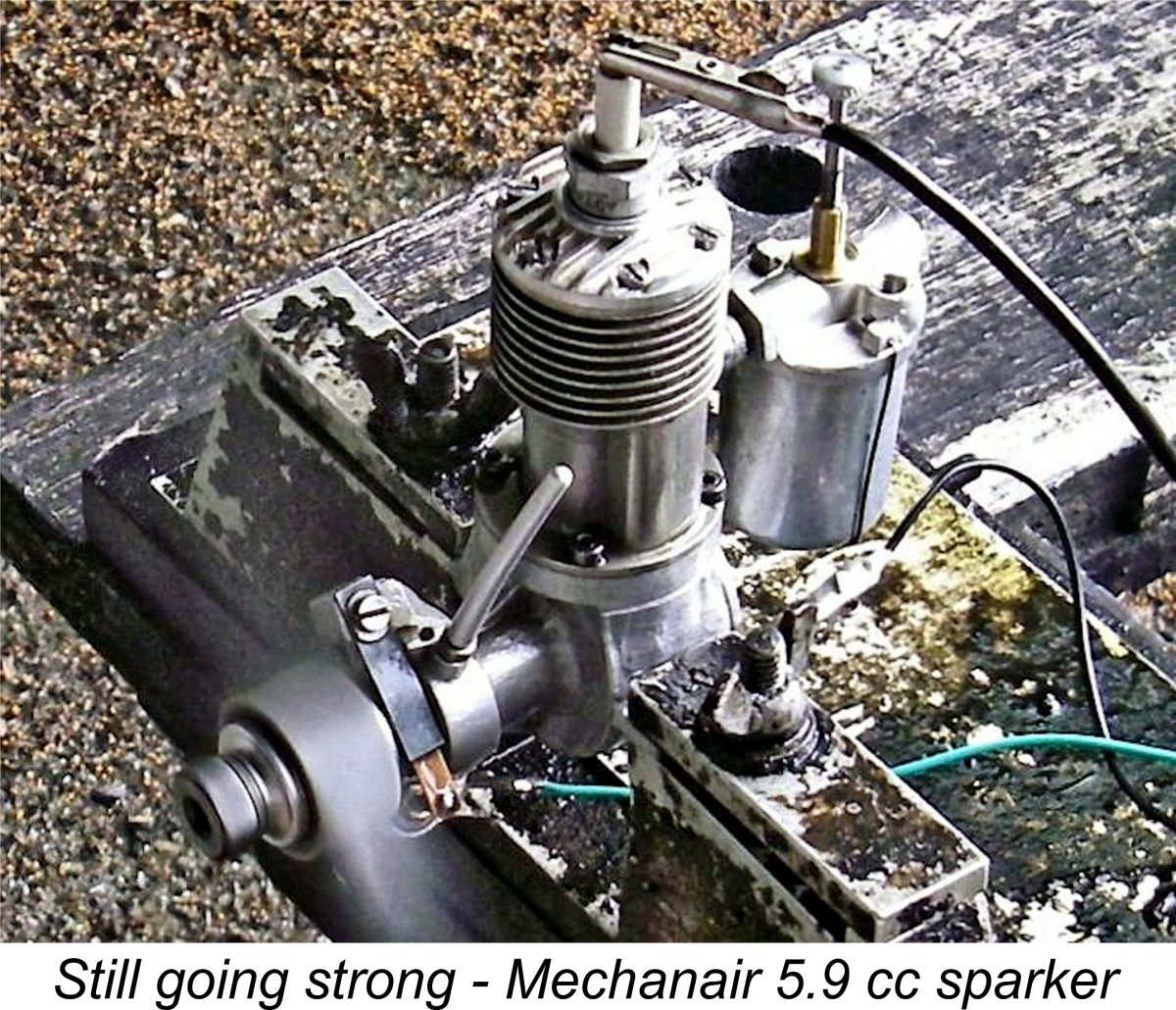
In all honesty, I would not rate this engine as a particularly easy starter - it's a little too "fuel-finicky" to deserve that rating. However, it has to be recalled that the engine was still relatively tight during this test. There's little doubt that starting would improve considerably if the engine was better freed up through some more running. On the bright side, once the Mechanair was running it performed very smoothly indeed with absolutely no misfiring or sagging, draining the tank dependably on all props tried. Moreover, it displayed no symptoms of mechanical distress at any time. There was some vibration, but it was by no means excessive. I'd objectively rate this engine's running qualities very highly. That having been said, there was no evidence of any significant power being developed. After putting a few slightly rich runs on the engine to free it up a bit, I began to take some prop/RPM readings. The engine turned the Taipan 11x5 prop at a smooth and steady but somewhat lacklustre 5,200 RPM, shifting a fair bit of air in the process but not developing much in the way of brake horsepower. I tried a much "faster" Zinger 11x4 wood prop, but the engine only got this one up to an equally smooth and steady 5,600 RPM. As things stood, this example of the Mechanair appeared to have already passed its peak output on the 11x5. This led me to try going the other way by using heavier loads. This proved to be the right way to go. The following data were eventually recorded:
As can be seen, the Mechanair was no ball of fire in the performance department, developing around 0.092 BHP @ 4,700 RPM. Still, those big props certainly move plenty of air, and the engine as it stands would undoubtedly do a creditable job of flying a large free flight sport or scale model. For such applications, the recommendation of an 11x6 airscrew seems entirely appropriate, since it would almost certainly allow the engine to operate at or near its peak in the air. However, I personally think that control line service might be a bit much to ask of this unit. At the end of this fairly lengthy running session, the Mechanair had freed up to a certain extent, although I'd still rate it as being relatively stiff when turned over. If given some additional running, I could easily see it freeing up to the point at which it might well get up to somewhere in the vicinity of 0.10 BHP @ 5,000 RPM, but not much more than that. The use of a methanol-based fuel would almost certainly release a little more power too, although the rather low compression ratio would probably inhibit operation on that fuel. The test engine remained in top-notch mechanical condition throughout, seemingly ready to do as much additional running as might be asked of it. Whatever its other shortcomings, the underlying quality of this engine shines through at every turn! The Dunham Mechanair Replica
It appears that the company was initially established to service the agricultural industry by supplying spare parts and undertaking repairs. However, the members of the Holmes family were all keen vintage model fliers. Recognizing the conflict between supply and demand which had made the acquisition of original vintage engines problematic for flying purposes, they evidently reasoned (somewhat optimistically as events proved) that a sincere attempt to create a range of high-quality replicas or retros would be well supported by their fellow British vintage enthusiasts. From the outset, the company’s design policy was to keep their replicas as true to the originals as possible while not replicating and thus perpetuating any obvious design faults. In keeping with this very rational philosophy, their engines displayed a number of design improvements over the originals, while recognizably retaining the character of those models. The first model engine produced by Dunham Engineering beginning in March 1981 was a look-alike rendition of our main subject, the Mechanair 5.9 cc model. This unit was clearly based upon the earlier “Blackhead” version of the original Mechanair, since it lacked the red head but replicated the original black cylinder finish. However, it must be said in all honesty that the Dunham “replica” differed sufficiently from the original that it may perhaps be more properly referred to as a look-alike than a true replica. For one thing, the bore was increased to raise the displacement from 5.9 cc to 6.9 cc - a gain of some 17%. Along with this increase went improvements to the design of the cylinder transfer and exhaust ports as well as an improved piston baffle configuration.
The resulting engine was a fine-running and durable Mechanair look-alike having a performance which was markedly superior to that of the originals. The Dunham Mechanair was also made available as a kit of parts in varying stages of completion. One offering was a complete set of finished parts requiring only assembly. The other was a home machinist's kit of castings and materials complete with working drawings. Despite its many fine qualities, this model did not prove to be a strong seller. This was likely due in large part to the significant departures from the original, which called into question the engine’s right to be called a replica as such. The relatively low sales figures achieved suggest that this may have put off a fair number of potential customers. As far as Dunham’s US distributor, the late and much-missed Bert Streigler, could later recall, around 75 examples of the Dunham Mechanair were sold in total in the USA. This was at least half the total, since Alan Holmes recalled later that overall production did not exceed 150 units. The number of examples sold as kits and subsequently completed by their owners is unknown. The Dunham Mechanair saga highlights a recurring problem (if we can call it that!) with replica engines. This is their tendency to quickly become viewed as collector’s items in their own right, with a consequent strong discouragement to their use for actual flying, followed by their semi-permanent disappearance into people’s collections. The Dunham Mechanair is a case in point – despite their considerably longer production life, far fewer of the replicas were made than the originals! Consequently, the engine quickly became viewed as a highly desirable collectible in its own right, resulting in a large proportion of them being purchased by collectors as opposed to active model fliers. It’s thus doubtful that many of them ever got used for actual flying purposes, which rather sidestepped the manufacturers’ intent in offering them in the first place ……….. Indeed, the fact that a substantial number of original examples of the Mechanair appear to have survived in very good condition meant that it was by no means out of the question to find an original rather than settle for a replica. The most commercially-successful replicas are those of original engines which are rarely if ever encountered in the metal. The Mechanair did not fall into that category. Conclusion The original Mechanair engines must be seen as a very sincere attempt on the part of their manufacturers to provide British modellers with a high-quality powerplant having a useful sport-flying performance coupled with a very long working life. In my personal view, these finely-crafted engines rank among the best of the early post-WW2 British general-purpose spark ignition offerings.
For a time at least, diesels were not widely available in sizes large enough to directly challenge sparkers in the Mechanair's displacement category, extending their working lives somewhat. However, this soon began to change with the mid 1947 appearance of larger diesels such as the ETA 5 and the D-C Wildcat. By the middle of 1948 the switch to diesels in Britain had become a landslide, with only a few die-hard spark ignition adherents remaining active. The 1948 introduction of the glow-plug to the British market also played a significant role. This spelled the end of the Mechanair and the vast majority of its fellow sparkers in commercial terms. The engines were set aside in favour of the all-conquering diesels (and glows in the larger displacements). They either went into the modellers' "maybe someday" boxes or were thrown out, since there was no second-hand market for them at the time. From a present-day standpoint, the one positive aspect of this rather speedy eclipse was the fact that many of the early post-WW2 sparkers were taken out of service long before they were anywhere near worn out. As a result, a significant number of examples were seen by their owners as being in too good condition to be simply thrown out. Since there was then no significant demand for second-hand sparkers, these engines were set aside "just in case" and subsequently forgotten. Many such engines have survived down to the present day in excellent condition under the dust, grime and oil gum, having been re-discovered 60 years later by the descendants of their original owners and placed on eBay. The exceptions to this rule were the fairly numerous examples which were tried by their owners using glow-plug ignition. These engines almost invariably lost their timers, while many were modified in various other ways. The sad thing about this from the standpoint of a present-day collector is that spark ignition engines of this type and era seldom work well on glow-plug ignition - for one thing, their compression ratios are typically far too low. In addition, they may have difficulty accomodating the somewhat higher working stresses imposed by glow-plug operation with its relatively narrow ignition timing range. Accordingly, few of these units remained long in service - just long enough to lose their originality or to experience structural failure. Regardless, nice complete examples of the Mechanair like those illustrated here still seem to show up from time to time. Any enthusiast having the chance to acquire such an engine should give it very serious consideration - this is a quality product! ____________________________ Article © Adrian C. Duncan, Coquitlam, British Columbia, Canada First Published August 2019
|
||
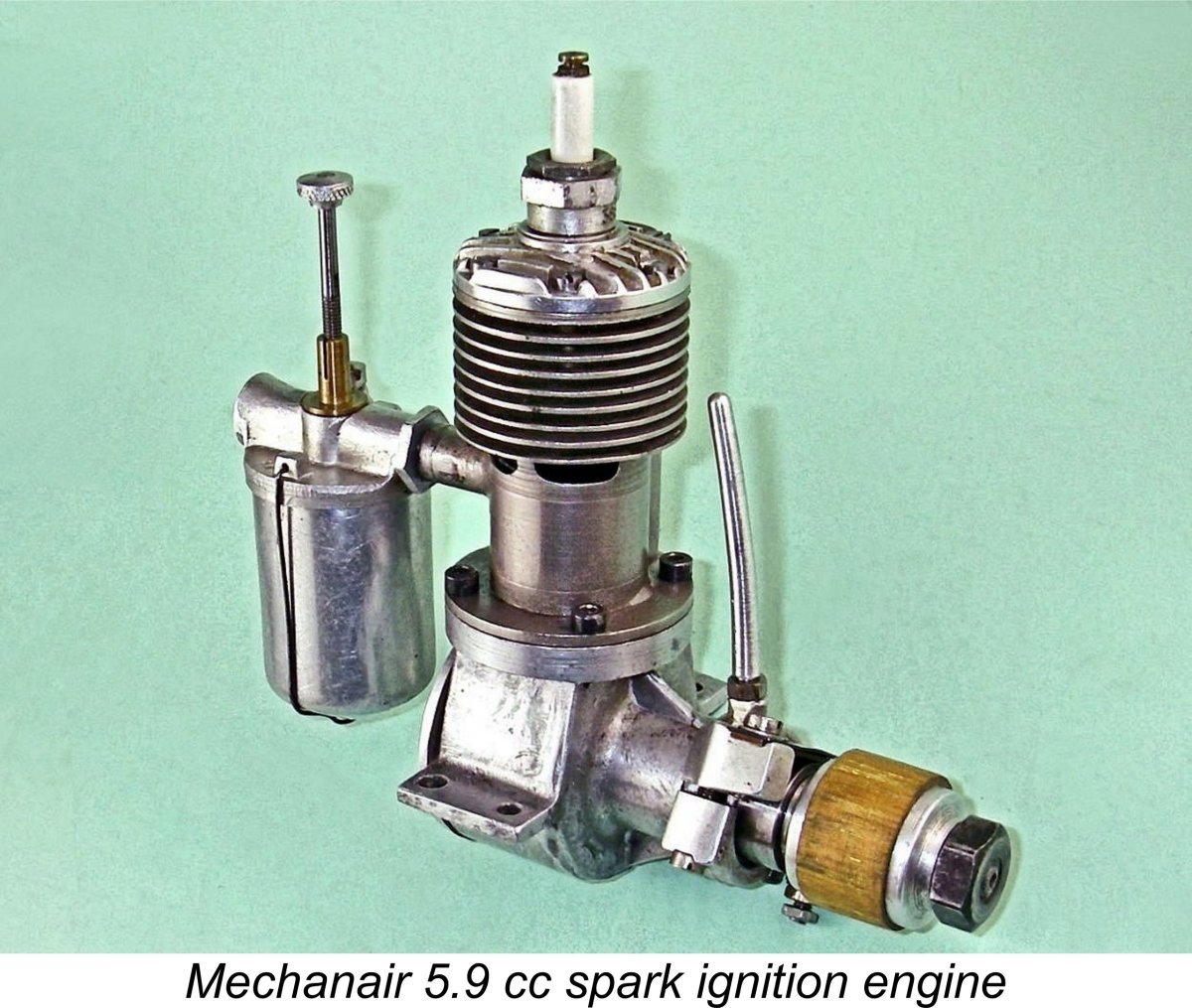 Here we’ll share a look at a worthy representative of the first wave of new domestic model engine designs to appear on the British market within the first year following the conclusion of WW2. We’ll be examining the Mechanair 5.9 cc spark ignition engine which was manufactured to very high standards in Birmingham, Warwickshire (now part of the West Midlands conurbation) between the first half of 1946 and early to mid 1948.
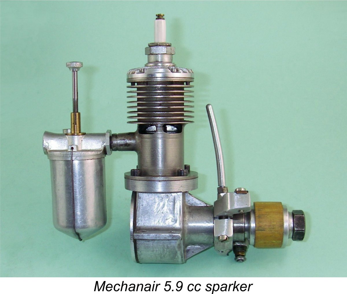
 Many previous commentators have characterised the Mechanair as a late 1946 development of the Astral 5.9 cc offering which had first been manufactured and marketed earlier in 1946 by the Astral Aero Model Company (Astral) of Dixon Lane Road in Leeds, Yorkshire. However, as far as I'm aware none of them have never presented any firm evidence to support this contention.
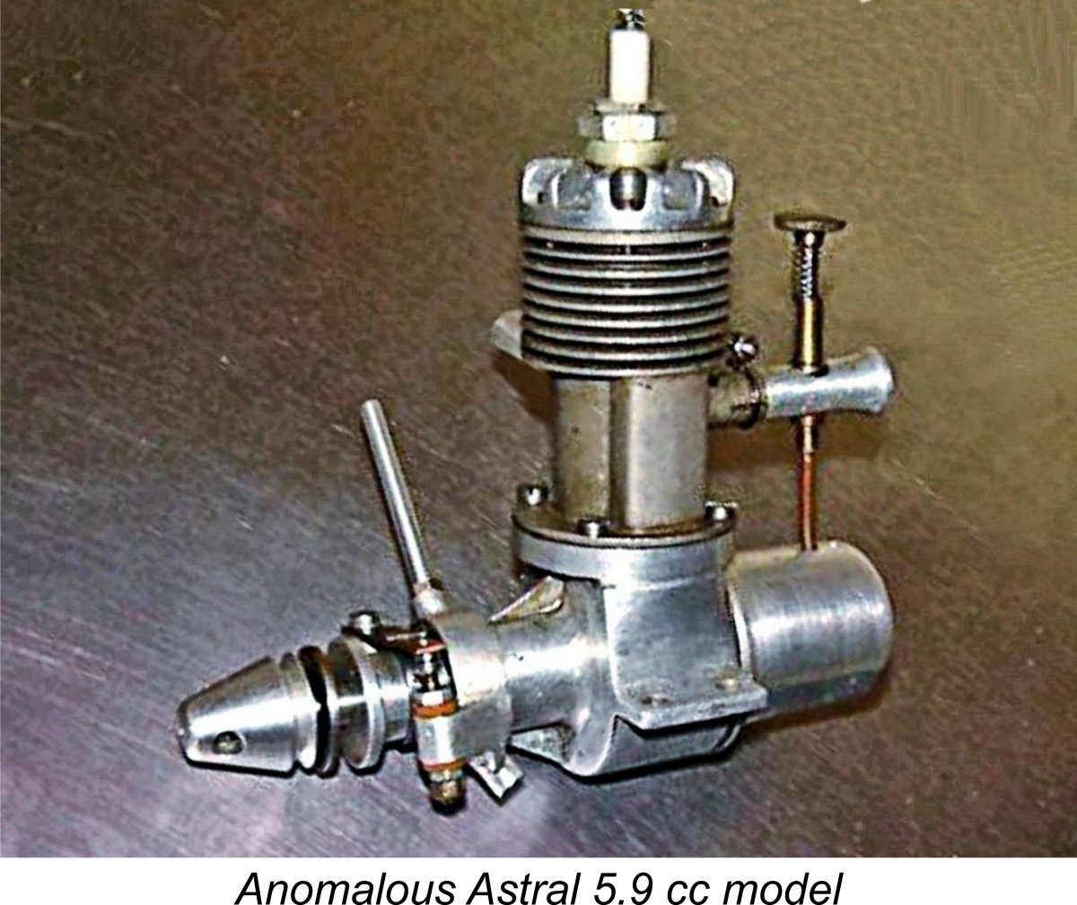
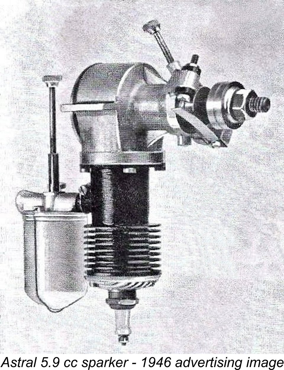
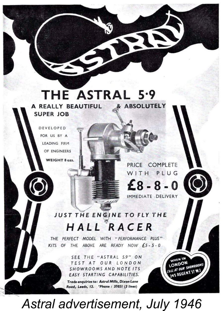 The company had certainly begun to market the more familiar illustrated version of the engine as of July 1946, when the advertisement reproduced here at the left appeared in that month’s issues of both “Model Aircraft” and “Aeromodeller” magazines. Astral continued to market this model under their own name up to at least December 1946, as witness the “Model Aircraft” advertisement from that month which is reproduced below. However, for reasons which are now unclear, Astral evidently abandoned their marketing role shortly thereafter, since by February 1947 we find what appears to be the same engine being marketed by Gamages Ltd. under the Mechanair name, with no reference whatsoever to Astral. The relevant Gamages advertisement is reproduced in its place below.
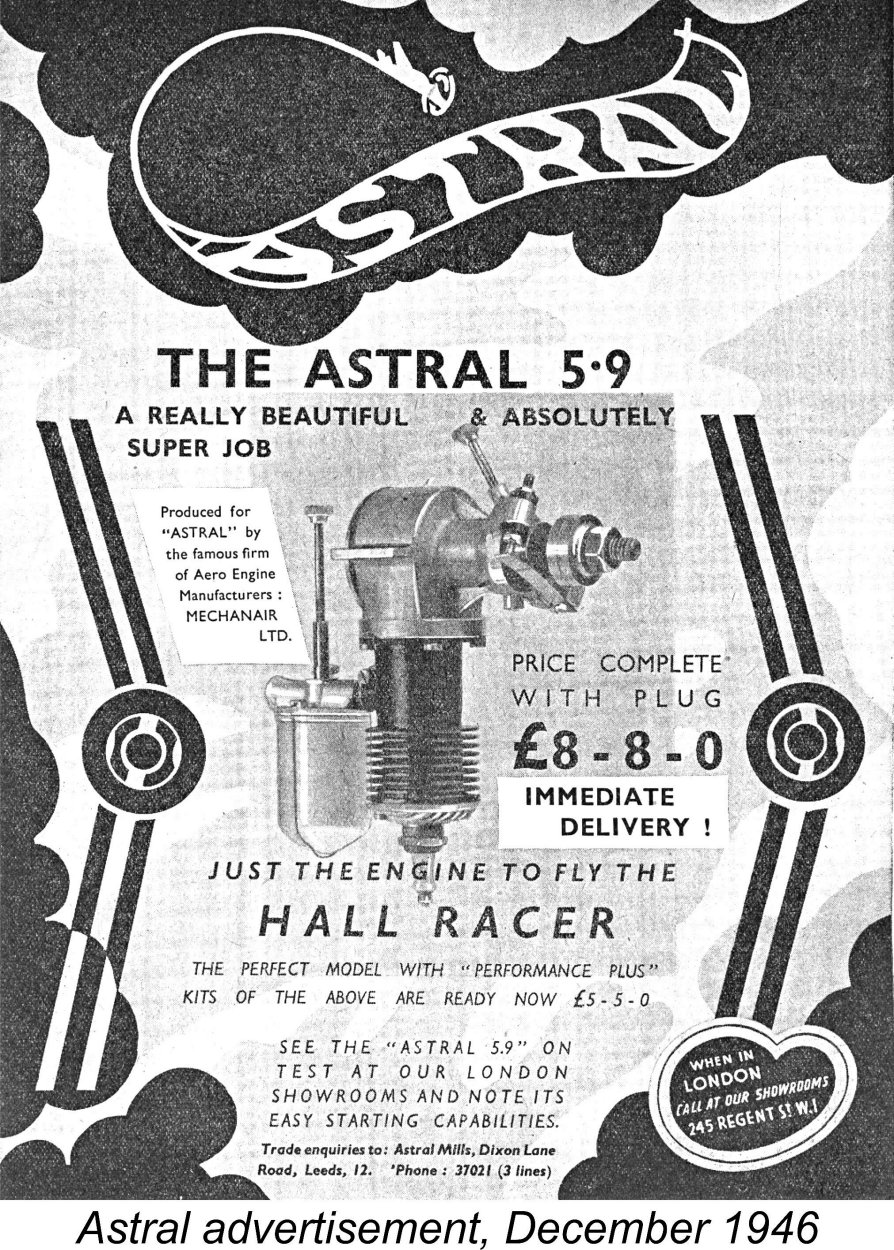
 the conflict. If this was indeed the case, the company may well have seen model aero engine development as a new line of work which might supplement their post-war business efforts. Others certainly did so.
 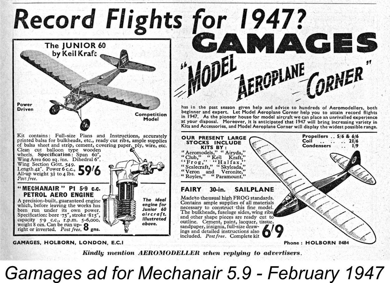 The withdrawal of Astral from the venture was by no means a body blow to Mechanair. On the contrary, they continued to market the motor under their own name, even using the same advertising image as that formerly featured by Astral. This seems to prove that Astral never actually owned the Mechanair design - they simply marketed it. The instruction sheet supplied with the later 1947 Mechanair "Red-Head" model (see below) stated that the engines were then being distributed by a firm called Simons Concessionaires Ltd. of Piccadilly Arcade, New Street, Birmingham 2.
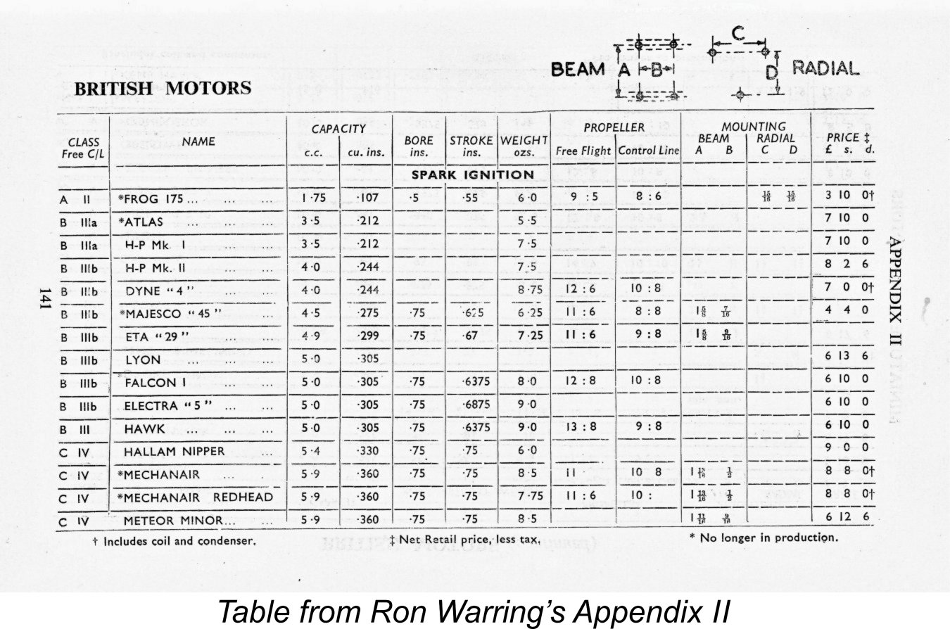
 This error in the table is particularly difficult to explain given the fact that the preceding entry, the Hallam Nipper, was quoted as having exactly the same bore/stroke dimensions, but its displacement was correctly cited as 5.4 cc based upon those
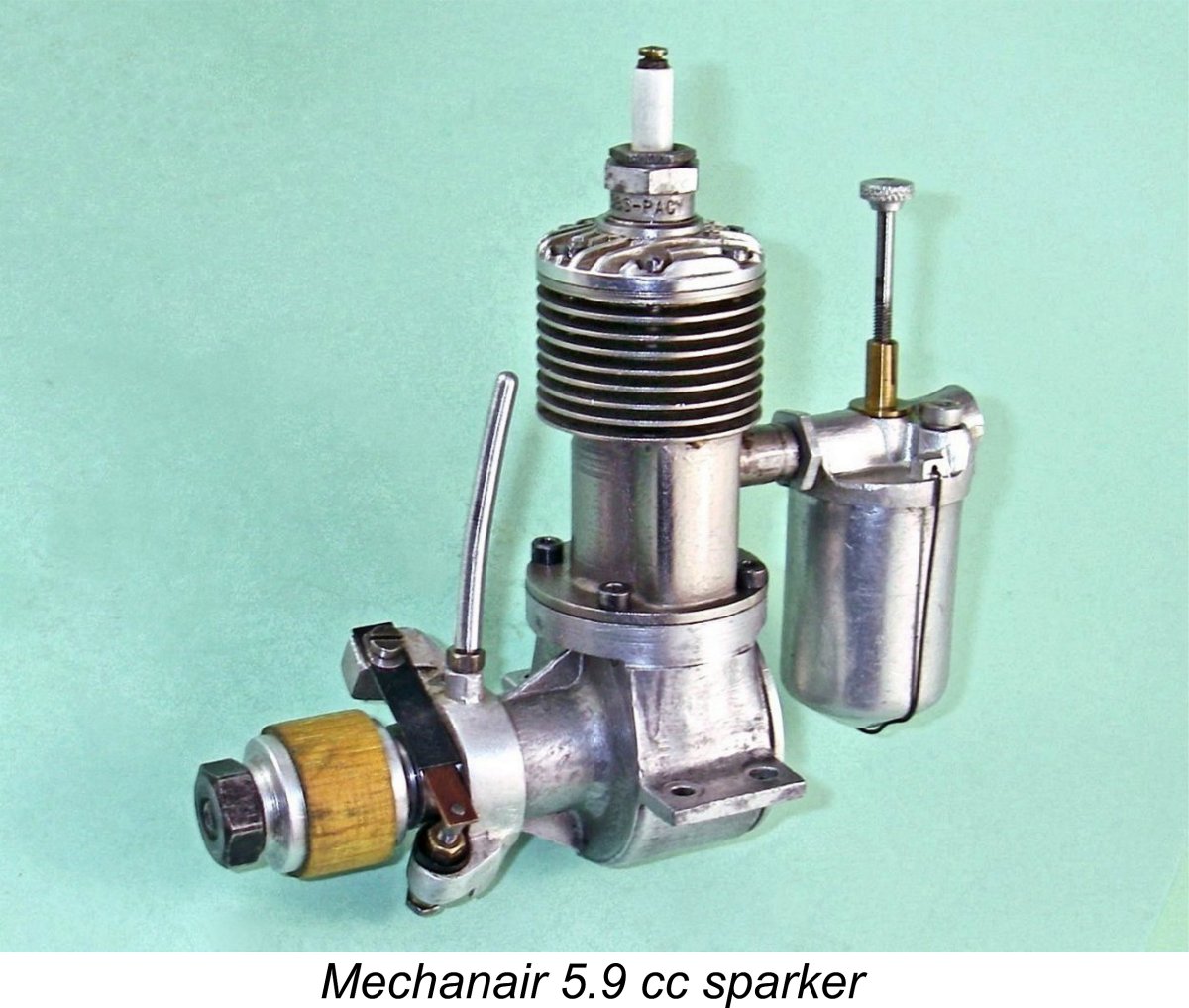
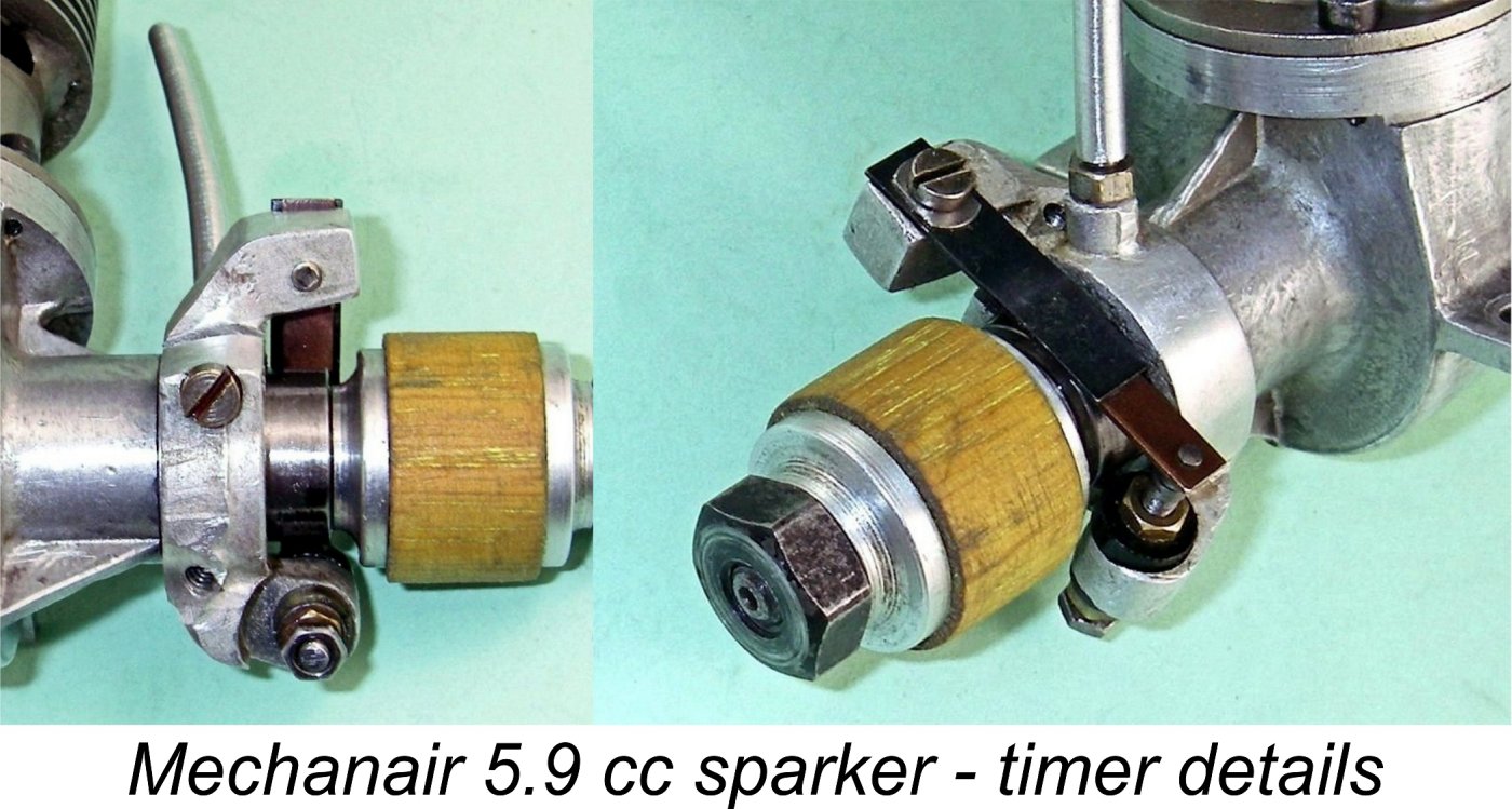 The engine was equipped with a well-designed open-frame timer which was actuated by a separate centrally-drilled hardened steel steel cam mounted on the protruding front of the crankshaft. This cam was secured to the shaft using an Allen-head set screw which engaged with a depression in the shaft surface to secure the cam’s radial location. Two alternative locations were provided for the timer control arm, allowing the arm to be advantageously positioned relative to the engine’s mounting configuration (upright or inverted). The design of the control arm itself seems to vary – I’ve seen quite a variety of such components on these engines. The most commonly-encountered design is a relatively short arm with a sizeable knurled control knob, looking very much like the later needle valve controls.
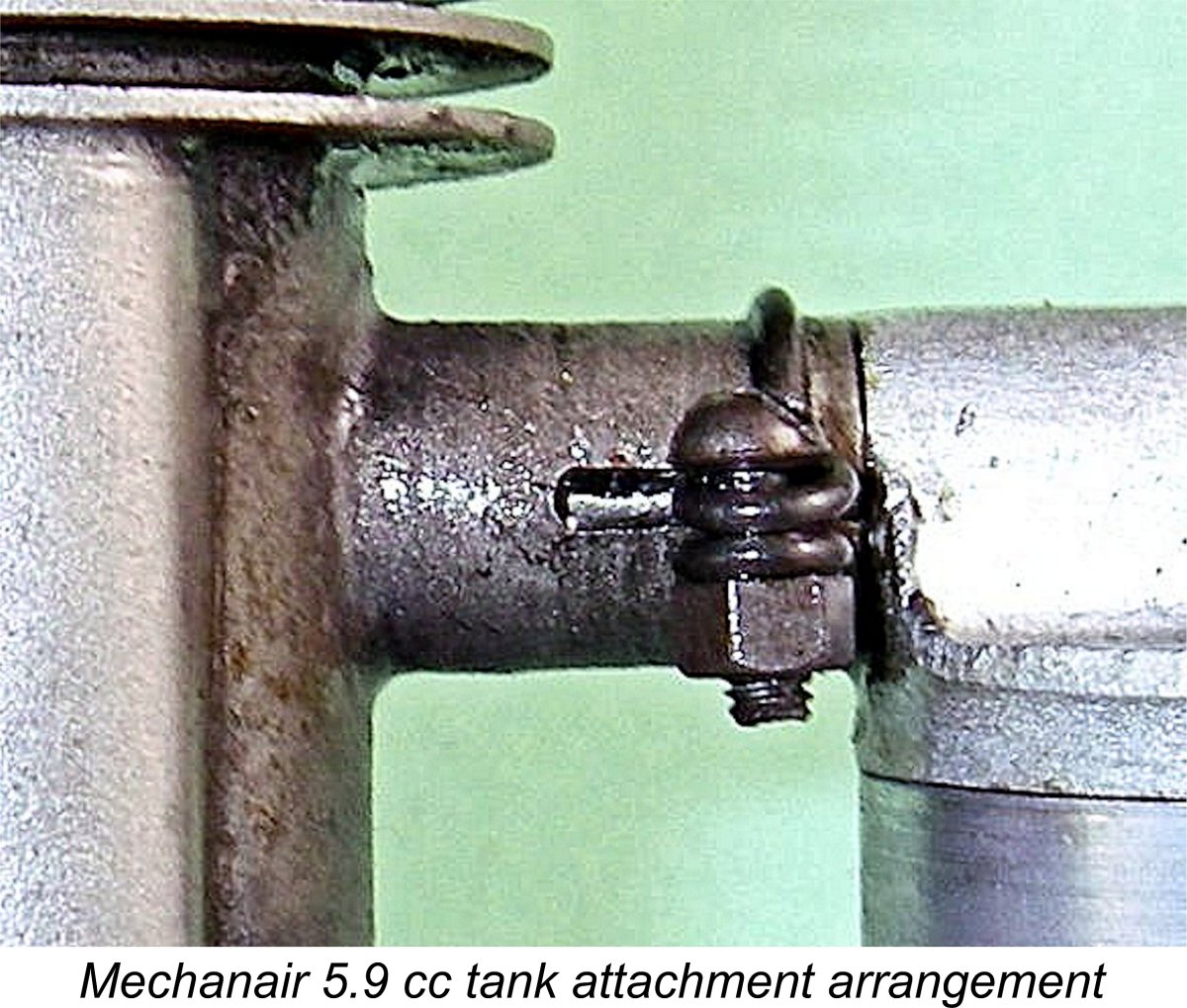 The alloy prop driver bore against the front face of the steel cam with no taper or other means of locking it to the shaft – complete reliance was placed upon friction between the faces of the cam and the driver. This arrangement was presumably directed towards protecting the crankshaft from crash damage by allowing for prop slippage under high levels of impact stress. With the very low starting torques associated with spark ignition, the assembly would not be expected to give trouble during starting. Later testing proved this to be the case provided the prop was really well tightened to begin with.
 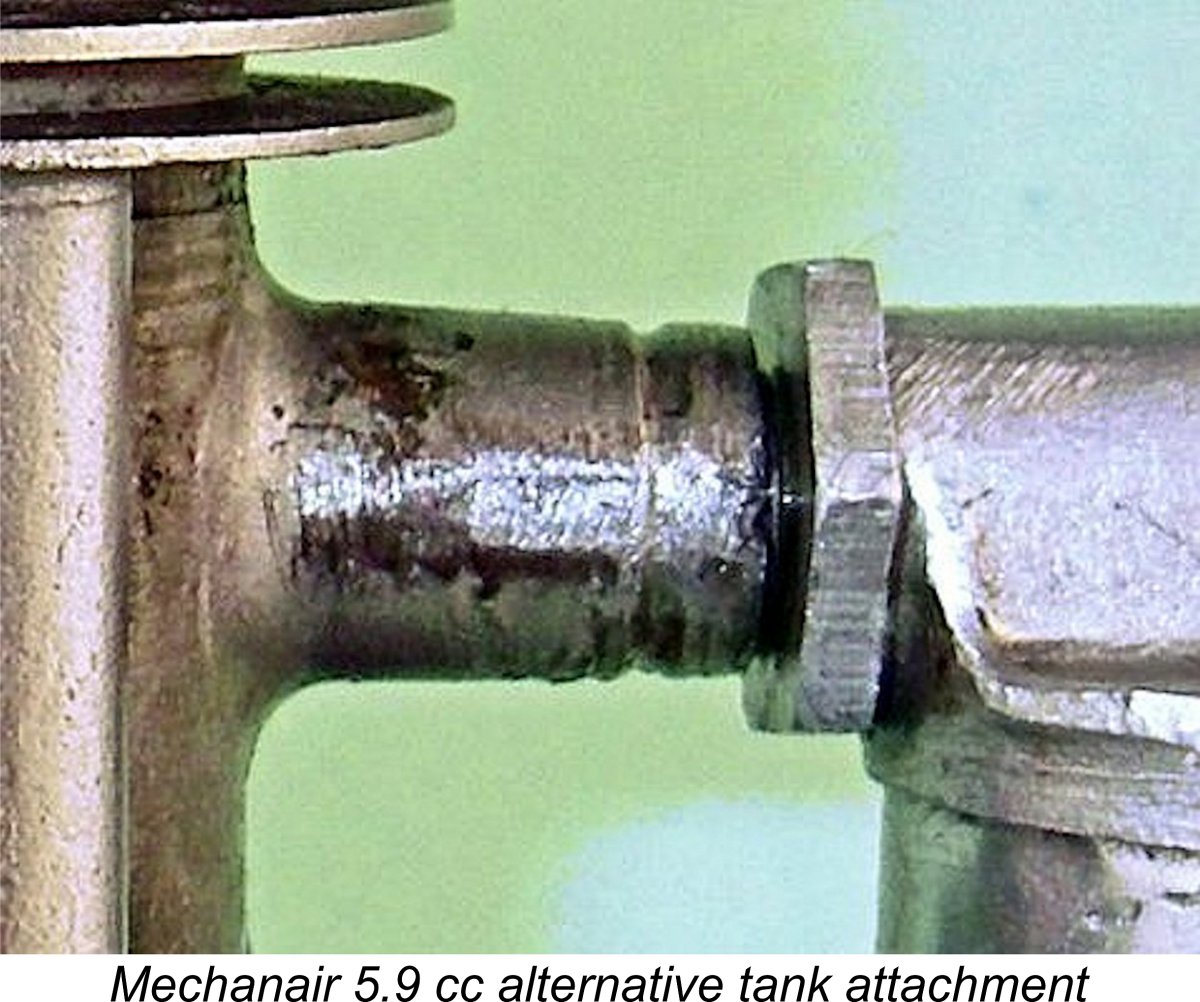 threaded extension has been very neatly soldered into it. The intake venturi is internally threaded and screws on to this extension, being held in position by a lock nut which bears against the delivery end of the venturi. A seemingly more dependable arrangement, it must be said, but offering no "give" in the event of an impact.
 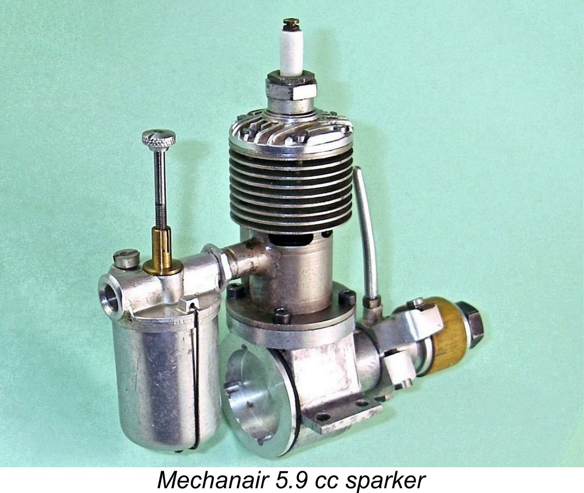 It is possible that this is a test arrangement which was applied to some examples, presumably after the introduction of the nickel plating on the cylinder. If so, it was quickly abandoned - almost all surviving examples of these engines feature the split spigot and wire circlip for carburettor mounting. That having been said, I’d be interested to learn of any other examples featuring this alternative form of carburettor mounting.
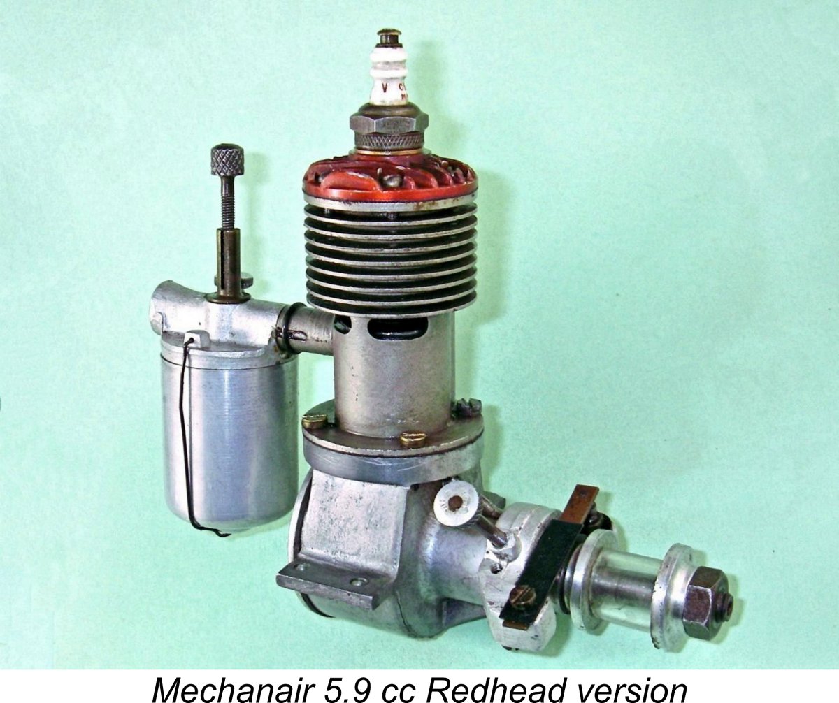
 On this variant, the nickel plated cylinder was retained, as was the split spigot and wire circlip system for tank attachment. In fact, apart from the head colour there are no externally-apparent differences between the two variants apart from the use of slot-head screws in place of Allen-head screws for cylinder retention.
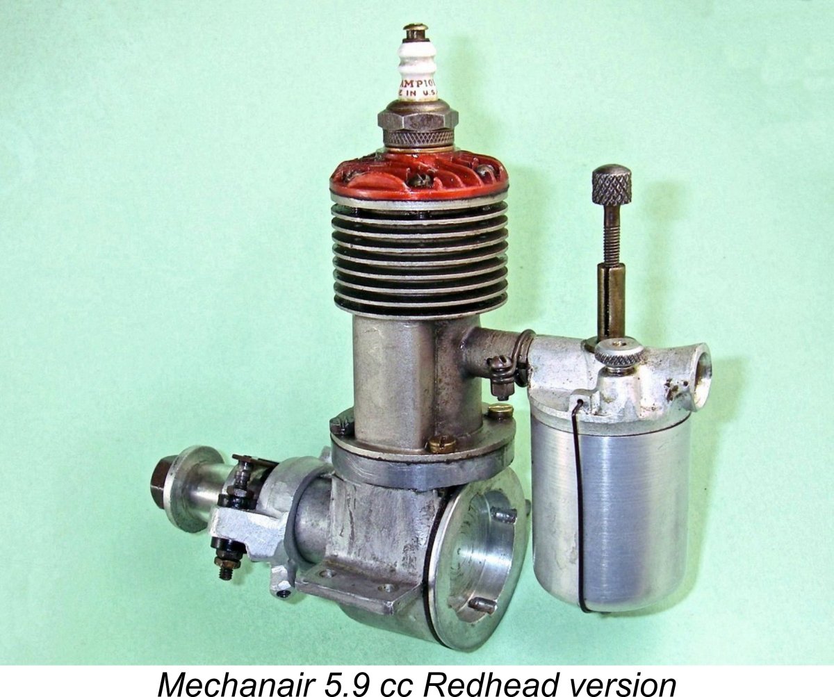
 Most previous commentators have cited 1949 as the year in which Mechanair production ended, but this does not appear to be correct. The basis for my statement is the explicit notation in the previously-cited Appendix II table in Ron Warring’s book that the Mechanair designs were “no longer in production” as of the compilation date of that table. A good deal of internal evidence derived from an analysis of its contents adds up to effective confirmation that the compilation of the table in question was completed by late 1948, which pretty much establishes the fact that as far as Warring was aware, Mechanair production had ended as of the latter part of 1948 and quite possibly some time earlier. However, the engine was evidently still in sufficiently wide circulation and use that Warring felt it worthwhile to include it in his table, along with a few other models of similar status.
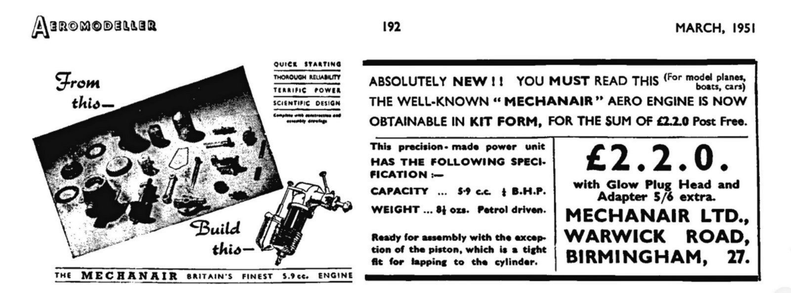
 Wanting to re-live the experience of a 1940's new Mechanair owner to the maximum extent possible, I dispensed with a preliminary test run on glow-plug, jumping right in with the spark ignition system hooked up. In the same spirit, I chose to retain the seemingly original antique Pacy spark plug, thus keeping the Mechanair as supplied in all respects.
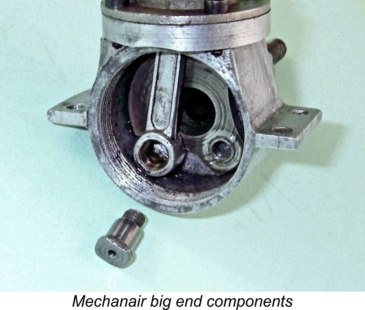
 For some unaccountable reason, this is exactly what had happened to my engine - the crankpin was half-way out of its thread! Since I had never turned the engine backwards at any time, I can only assume that the engine had suffered an internal "inspection" by a previous owner who had failed to re-tighten the crankpin properly. Alternatively, perhaps someone did try to run it backwards - since the cam is ground to a symmetrical profile, that would be only a matter of re-positioning the timer.
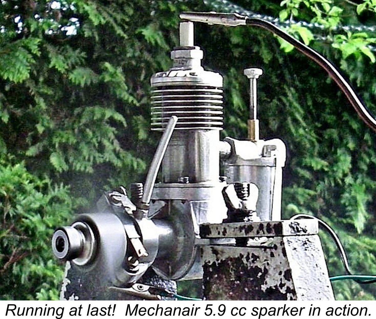
 The best approach proved to be to give the engine one choked flick to get fuel up to the carburettor, followed by a "dry" prime administered with the exhaust ports closed. The idea here was to minimize the opportunity for fuel to pool in the crankcase. Using this technique, the engine proved to be a dependable if not necessarily instantaneous starter, although it continued to bog down if I somehow got more fuel into the cylinder than it wanted. That was all too easy to do, unfortunately - any inadvertently excessive choking or unburned port prime went straight down to add to the pool in the crankcase.
 No discussion of the Mechanair 5.9 cc sparker would be complete without reference being made to the fine look-alike manufactured in small numbers between 1981 and 1987 by Dunham Engineering of 12 Lawns Ave., Orrell, Wigan, Lancashire, England. This company had been established some time previously by Alan Holmes Sr. in partnership with his two sons Alan Jr. and Barry. Alan Sr.’s wife Joyce acted as the firm’s business manager, making this very much a family business. A detailed review of Dunham’s model engine manufacturing activities may be found
| |