
|
|
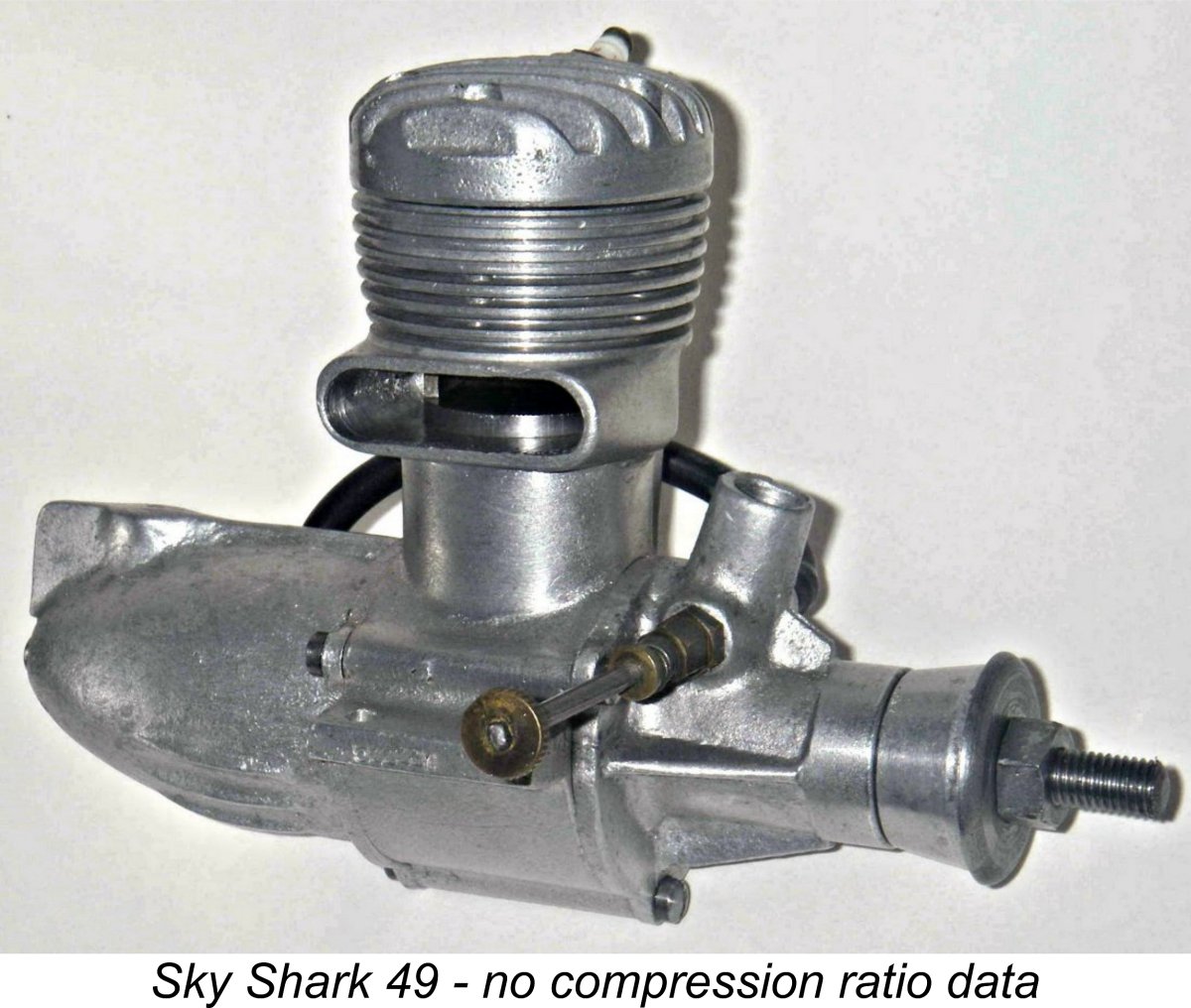
Measuring the Compression Ratio of a Glow-Plug or Spark Ignition Engine As any knowledgeble model engine user is aware, compression ratio can have a significant influence upon a glow-plug (or spark ignition) engine’s fuel preferences and ideal speed of operation as well as the optimal heat rating of its plug. This being the case, it’s important to know your engine’s But how do you determine the compression ratio of a given engine? Well, if the engine retains its instruction sheet, the manufacturer may well have specified the compression ratio. This is fine, although in my personal experience the actual figure can depart from the manufacturer’s number to a potentially significant degree. Moreover, many older classics or second-hand engines are no longer accompanied by their manufacturer’s data, nor is the required information readily available from other sources. The illustrated 1952 Sky Shark 49 from Japan was a case in point in my experience (its compression ratio turned out to be 7:1). In either case, there’s no substitute for direct measurement of your particular engine. OK ……. so how do you go about measuring your engine’s compression ratio? That’s what this article is all about! Heving noted that these comments apply to spark ignition engines also, please read on ………..
In passing, it’s worth noting that the quite distinct terms “displacement” and “capacity” have often been used interchangeably and hence incorrectly in the past. The British writers of the ‘Forties and ‘Fifties were particularly guilty of this. It should be clear from the previous paragraph that the engine’s capacity is the sum of its displacement plus its combustion chamber volume at top dead centre. Change the latter volume (as you can do freely at any time with a diesel, for example), and you’ve changed the capacity. The only fixed measure of an engine’s size is its displacement. Accordingly, that is the term that should always be employed. In mathematical terms, if we let CR represent the compression ratio, V represent the engine’s displacement and v represent the engine’s combustion chamber volume at top dead centre, then we can use the following formula: CR = (V + v) / v
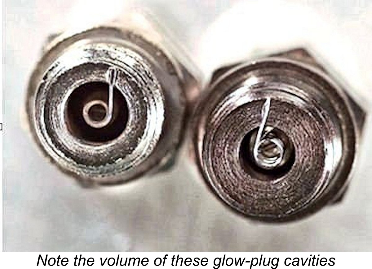
To take a simple example, let’s consider an engine having a displacement of 5.0 cc and a combustion chamber volume at top dead centre of, say, 0.7 cc. Adding the displacement of 5.0 cc to the combustion chamber volume gives us the sum total of 5.7 cc (the engine’s cylinder capacity). If we then divide that 5.7 cc figure by the combustion chamber volume of 0.7 cc, the units cancel out and we get a compression ratio of 8.14:1. Now it’s important to understand that this calculation defines the engine’s geometric compression ratio. It represents the degree to which the gas in the cylinder would be compressed if the compression started at bottom dead centre and continued all the way to top dead centre. In reality, however, this idealized condition is never encountered. In an atmospherically-scavenged two-stroke engine (no tuned pipe), no pressure can build up in the cylinder until the exhaust port finally closes as the piston moves upwards because any gas displaced by the rising piston will simply be forced out through the exhaust port (or back down the transfer port). Consequently, actual compression of gas in the cylinder can only commence after the exhaust port closes. Moreover, the volume of gas available to be compressed is limited to the total volume of the cylinder above the top of the exhaust port, which will be considerably less than the volume above the piston at bottom dead centre. However, the combustion chamber volume at top dead centre remains unchanged when viewing the situation in this light. It follows that if we take the volume of the cylinder above the exhaust port (including the combustion chamber volume) and divide that by the combustion chamber volume alone, we will derive a significantly reduced compression ratio, but one which nevertheless more accurately reflects reality in terms of the degree to which gas is actually compressed during operation. This is termed the effective compression ratio. The problem with effective compression ratio is that the cylinder pressures that it theoretically produces aren’t necessarily realized during operation of a given engine. Indeed, they may not even be constant. They can be affected by such factors as temperature, ambient atmospheric pressure, oil content in the fuel, engine speed variations, related changes in scavenging efficiency and the use of tuned pipes or superchargers to elevate the induction pressure in the cylinder. The actual operating compression ratio, termed the dynamic compression ratio, may therefore vary somewhat from the theoretical effective ratio. For this reason, almost all model engine manufacturers routinely quote the geometric compression ratio when characterizing their designs, since that is a fixed design characteristic. Long usage has more or less conditioned users to compare engines on this basis rather than on effective or dynamic compression OK, so now we hopefully have an idea of what we’re trying to measure. How do we go about it? Well, if you’re stayed with me this far you’ll understand immediately that we will need to know both the engine’s displacement and its combustion chamber volume at top dead centre. These two volumes are graphically depicted in the image at the right. Knowing those figures, we simply use the formula set out above to calculate the geometric compression ratio. In most cases we’ll know the engine’s displacement already. However, if the engine is an unknown quantity, we’ll have to measure it up to determine its displacement. I won’t bore you with the math – suffice it to say that the formula is: Displacement = 0.7855 x bore x bore x stroke. It follows that obtaining the displacement of an undocumented engine requires the measurement of the engine’s bore (or piston diameter) and its stroke (the distance that the piston moves from bottom dead centre to top dead centre). How you go about doing this depends on the measuring equipment on hand as well as factors like your willingness or ability to dismantle the engine. There are ways of measuring both bore and stroke Assuming that one way or another you’ve determined the engine’s displacement, the next requirement is to measure its combustion chamber volume at top dead centre. Here it’s important to understand that this volume will include the internal volume of the element cavity in the glow plug (or spark plug) itself. People tend to ignore this contribution to the overall volume, but it can actually be quite significant, particularly in small-displacement engines and with "hot" large-cavity glow-plugs like the left-hand example in the image at the left. Bear in mind that different plugs having different cavity sizes will have varying effects upon a given engine's compression ratio. Accordingly, the engine's compression ratio can vary to a surprising degree with different plugs, particularly in the smaller displacement categories.
Begin by removing the plug from the engine, thus securing direct access to the combustion chamber through the plug installation hole. Then set the engine very carefully at top dead centre and secure the shaft by some means to keep it at that point.
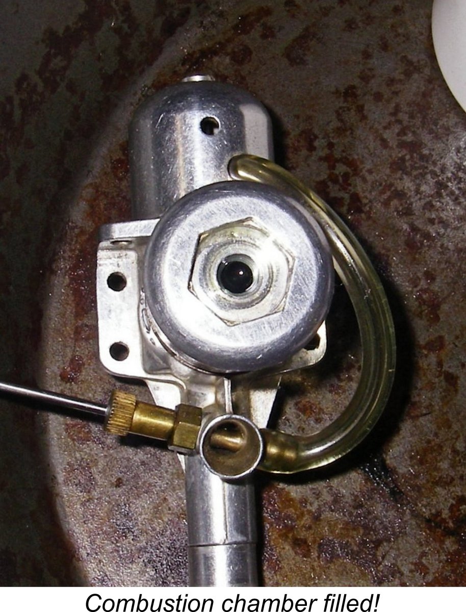
With the engine held in an upright position and the piston still at top dead centre, hold the nozzle directly over the hole and use the syringe plunger to start very slowly dripping oil from the syringe into the plug installation hole. Do this drop by drop rather than in a steady stream, making very sure that all the oil goes down the hole. The oil will of course begin to fill the Keep on syringing oil drop by drop into the combustion chamber until it is filled to the base of the plug installation hole and no more air bubbles emerge when the engine is rocked. Check that you’re still at top dead centre and Of course, as mentioned earlier you have to allow for the internal volume of the glow-plug. Being constitutionally lazy, I generally just add a few extra drops of oil based upon an eyeball estimate obtained through examination of a typical plug used in that engine. However, you can (and probably should!) go to the trouble of determining how many drops of oil it actually takes to fill the plug's element cavity. Even better, if you have the required knowledge and equipment you can easily calculate this additional volume through direct measurement of the plug cavity's dimensions, making a small allowance for the volume of the element itself. Your choice....... The final step is to take a reading of the new position of the syringe plunger after you’ve completely filled the combustion chamber with oil. The difference between this figure and the starting point will be the amount of oil that it took to fill the combustion chamber. This of course is the combustion chamber volume, more or less. You’re almost done! Add the combustion chamber volume that you just determined to the engine’s known displacement and divide that figure by the combustion chamber volume alone. Presto – you have your engine’s geometric compression ratio! The JB Atomglow seen in the above illustrations turned out to have a geometric compression ratio of 7:1. After completion of this process, it is of course wise to drain the oil out of the engine to prevent oiling up the plug on the next start. If the engine was scrupulously clean when you took the measurement, you can return the oil to its original container. However, if it shows any evidence of having become adulterated with engine deposits, it's probably best to add it to the contents of the oil recycling container. I hope that this has been sufficiently clear. I’ll try to respond to any queries that may arise. Good luck!! ___________________ Article © Adrian C. Duncan, Coquitlam, British Columbia, Canada First published June 2017 |
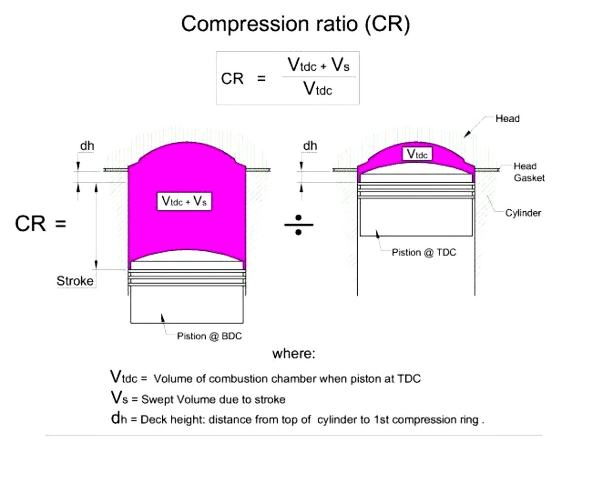 Before getting into the very simple techniques involved, it’s important to understand what it is that we are trying to measure before we try to measure it! In very simplistic terms, the compression ratio of an engine is a unitless numerical representation of the degree to which the fuel mixture in the cylinder is compressed by the rising piston on the upward compression stroke. At its most basic level it is the ratio between the volume of the cylinder above the piston crown at bottom dead centre (its capacity) and the volume of the combustion chamber at top dead centre when combustion occurs. The difference between the two volumes will be the engine’s swept volume, or displacement. The attached diagram will hopefully clarify the term somewhat.
 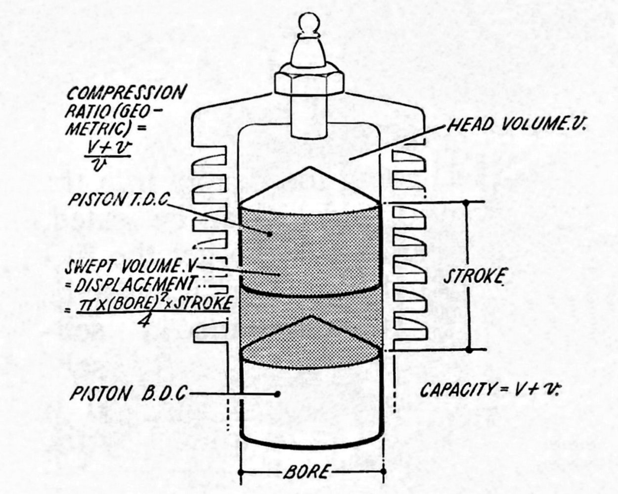 This is the formula which appears both in the graphical representation presented above and in the figure at the left. Put into words, the compression ratio is obtained by adding the engine’s displacement and its combustion chamber volume at top dead centre and then dividing that sum by the combustion chamber volume alone. Hopefully the attached diagram extracted from the 1958 publication “Model Aero Engine Encyclopaedia” will help to further clarify this.
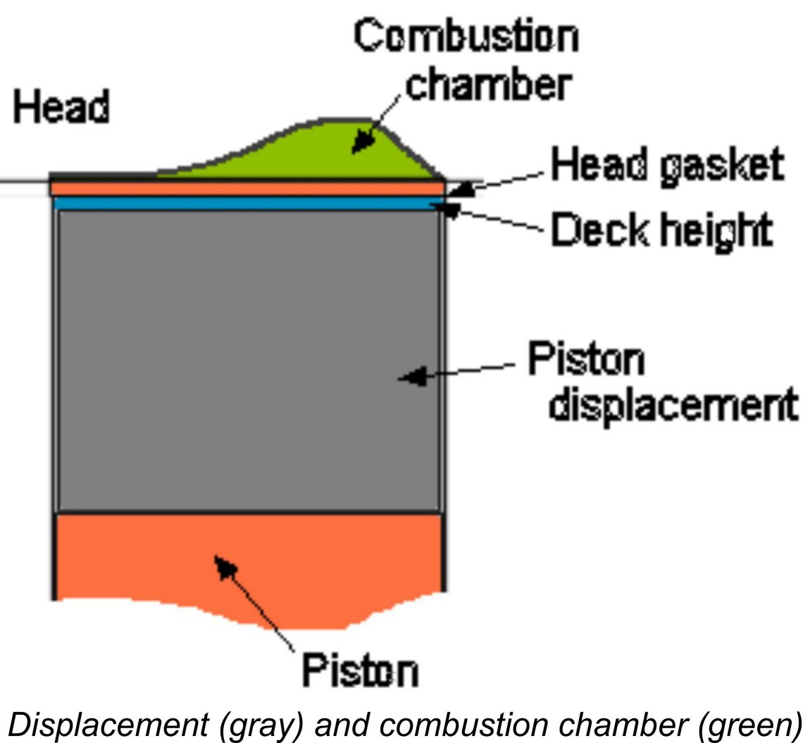
 To measure your engine's combustion chamber volume, you’ll need a small-capacity graduated plastic syringe like the one illustrated at the right. Suitable non-medical syringes are readily available very cheaply at many drug-stores. You’ll also need a small quantity of some form of engine-friendly low-viscosity oil. It’s critical that the oil be very free-flowing so that air bubbles can quickly move through it to the surface. I generally use
  Push the plunger of the syringe all the way in and then immerse the nozzle of the syringe in a small open container of oil. Fill it with oil by steadily pulling the plunger out. Once it's filled (plunger withdrawn to the max) hold the filled syringe with its nozzle pointing upwards and carefully push the plunger up to some convenient volume, which should

| |