
|
|
Canada's West Coast Wonders - the Queen Bee Engines
The "original" Queen Bee offerings with which we are concerned here were fine engines which were produced to very high standards by a small-scale artisan manufacturer. Their production took place in what amounted to a home workshop somewhat incongruously located in what is today the up-market Point Grey “university” district of Vancouver. A key factor in enabling me to tell this story was my being fortuitously put in touch with Hans "Johnny" Edwards of North Saanich, British Columbia. It turned out that Hans was actually a one-time teenage employee of the small family business which manufactured the Queen Bee engines. Although 88 years old when I made contact in early 2019, he remained as sharp as a tack, willingly sharing many vivid memories of his involvement with the Queen Bee venture. In addition to providing a number of "period" photographs, he was kind enough to support my research by passing along his own Queen Bee 29 spark ignition engine (no. 0118) which he had owned for over 70 years, having used it back in the day when the engines were current. This is another reminder of the urgent imperative which faces those of us who are dedicated to the preservation of model engine and aeromodelling history from the vintage and classic eras. Most of those who were directly involved during those eras have now left us, making it all the more important that we tap into the recollections of the relatively few such individuals who remain on deck. Without Hans’ input, many fascinating details of the Queen Bee story would have been lost forever. I’m also extremely grateful to my valued German friend Peter Rathke, who was instrumental in enabling me to acquire beautiful examples of the rarest Queen Bees of them all – the later .60 cuin. models. Without those engines to examine, my documentation of the range would have been seriously deficient. Now, having gratefully acknowledged the invaluable assistance that I’ve received, it’s time to get on with the story. I’ll begin with a general overview of the Queen Bee venture and the personalities involved, after which I’ll present some details of the various models in the order in which they appeared. Here goes …………….. The Queen Bee Story – an Overview The Queen Bee engines were designed and manufactured by a firm calling itself Salonen Brothers Tool & Engineering Works of 4569 West 10th Avenue, Vancouver. The main protagonist of this business was Al Salonen, a skilled toolmaker and precision engineer. The company name implies the involvement of at least one brother, but Hans Edwards retained no direct knowledge of any such person(s) beyond a vague recollection that one or more brothers may have helped Al with start-up financing. None of them evidently worked with Al in making the engines - at least, Hans never saw them doing so.
Al Salonen was clearly a keen aeromodeller from a relatively early age. Sheldon Jones found an article in the Vancouver Sun newspaper for June 8th, 1931 (right) which recorded his second-place finish in a multi-class model airplane contest held at Sea Island Airport (now Vancouver International Airport) under the auspices of the Vancouver Sun Airplane Model League. A noteworthy early example of media support for aeromodelling!
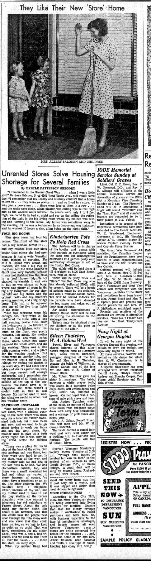
Al Salonen and his family were friends of the Edwards family, who lived nearby at 4534 West 4th Avenue at the time. Hans Edwards (b. Austria, 1931) was a teenage member of the Edwards family during the period under discussion. The family had emigrated from Austria to Canada in 1937 in response to Adolf Hitler's increasingly aggressive policies which were clearly leading towards war in Europe. The family name was Patzak, but Hans' father soon adopted the name Edwards after an American friend who had helped him greatly in earlier years. Due to the social climate of the WW2 and early post-war eras, when German-sounding names were not viewed positively, Hans was always known as "Johnny Edwards" until well past his teenage years. Hans (as I will continue to call him) knew the Salonen family well, including Al Salonen’s very pleasant and supportive wife and his two daughters Barbara and Carol. Having had the opportunity to observe Al closely for some years, Hans remembered him as being not the most affable of individuals. He evidently had a tendency to "speak as he found" very directly, with little regard for the effect of his comments upon the feelings of others. Hans remembered very clearly how curt and impatient he could be with those around him. Basically, he was a dyed-in-the-wool perfectionist who expected the same from others and did not suffer fools gladly, apparently never being hesitant or diplomatic about saying so! He was also very frugal, never owning a car until quite late in the day.
The company’s business address on the north side of West 10th Avenue between Sasamat and Tolmie Streets in Vancouver was not a location at which one would logically expect to find a precision engineering operation. The location was a few blocks east of the point where West 10th ended (and still ends today) at the rather formal entrance to the University of British Columbia (UBC) campus lying to the west of Blanca Street along University Boulevard. The immediate area was (and is) primarily residential – I lived very nearby for a few years myself while attending UBC following my 1966 arrival in Canada. However, the 4500 block on West 10th between Tolmie and Sasamat Streets was zoned for commercial use. It featured several well-known stores, including a spacious Safeway supermarket at the west end of the block. Just to the east of the Safeway store in the 4500 block on the north side of West 10th were several properties which had started life as small shops. One of these (no. 4569) served as Al Salonen’s home, with his workshop in the same building at the rear. This was an era in which many shopkeepers and small businessmen lived on their premises.
During the period in which the Queen Bee engines were manufactured, the teenage Hans "Johnny" Edwards was living with his familiy on West 4th Avenue and attending Lord Byng Secondary School a little to the south on West 16th Avenue. After school and on weekends, he used to head up to the Salonen workshop on West 10th, where he helped out with the production of the Queen Bee engines. His primary task was the making of the rather complex plastic fuel tanks with which the engines were equipped, but he also helped to set up the engines for testing prior to boxing and shipment. Apparently each and every one was tested before being cleared for sale. Hans recalled that the workshop was at the back of the Salonen residence at 4569 West 10th Avenue. To the rear of that was a small yard, where the engines were tested. Seemingly Al had to do this at certain specified times due to the noise, which understandably bothered a lot of people living on 8th or 9th Avenues behind the Salonen residence, to say nothing of the neighbors on West 10th. There’s simply no way that you’d get permission today for even a negotiated time-limited model engine testing program at this or any comparable location …………….different days!! Hans recalled that Al faced a seemingly endless series of problems and challenges in designing and constructing these units. He invariably worked away at these doggedly until he had them licked – there was no quit in his make-up! Overall, Hans confirmed that Al put a tremendous amount of effort into his As far as Hans could remember, Al made all the tooling and did all the machining himself, never employing any assistants apart from Hans at any time. His wife helped out a lot with various other tasks, including cleaning the tested engines, packing them and keeping the books. Al also made the dies, and Hans believed that he was directly involved in the casting process, although not at the 10th Avenue location - Hans never saw any castings being produced there. The Queen Bees are certainly notable for the excellent quality of their gravity die-castings. After starting out with a .24 cuin. (3.99 cc) model, Al further developed this unit into a very similar but slightly larger .29 cuin. design. This became his best-known engine. Both of these models were of course spark ignition units, but in November 1947 the modelling world experienced a seismic shake-up through Ray Arden’s introduction of the commercial miniature glowplug. This led Al to quickly develop a glowplug version of his established 29 sparker. More of all these units in due course below. In addition, there were one or two examples of a .60 cuin. model which appeared in prototype form in both glowplug and spark ignition variants. More of these too below in their place. Al also constructed some half-a-dozen experimental diesel prototypes of unknown design and displacement – I’m presently unware of any surviving examples, hence having no details to share. If any reader can fill this gap in my knowledge, I'd love to hear from you!!
Tim Dannels recalled having been told that one of Al Salonen's brothers arranged for the production of these boxes. also contributing some start-up capital to the venture. Whoever was responsible, it would seem that Al ended up with an excessive stock of boxes for the 24 which he understandably wished to use up. Even so, a number of boxes remained unused at the end of Queen Bee production, subsequently entering circulation among collectors – I have several brand new empty boxes myself, as do a few other local enthusiasts of my acquaintance. As far as I can ascertain, the Queen Bee engines were never advertised nationally either in Canada or in the USA. Indeed, they completely escaped the notice of any contemporary model engine commentators, either in North America or elsewhere. It appears that Al Salonen was able to sell all of his relatively limited output locally by word of mouth or newsletter announcements among the members of the various model clubs in the Pacific Northwest area of North America. Even today, the majority of examples that still surface from time to time seem to do so in that geographic area. Many (but not all) of the Queen Bee engines bore serial numbers. According to information compiled by my long-departed Canadian friend Ron Polglase (from whom I acquired several of my Queen Bees), the very first engines produced (examples of the .24 cuin. model) did not bear serial numbers, but soon thereafter the engines in the series began to display 4-digit serial numbers. The sequence apparently started at 0001 and went up to around 0200, after which the numbering was once again dropped. The numbering sequence seems to have continued wihout a break across the transition between the .24 and .29 cuin. models. It's not completely clear at what point in the sequence this switch occurred - all that we can say for certain is that the transition came prior to the manufacture of engine number 0102, which is a 29. The total number of engines of all types produced does not appear to have exceeded 400 units. Apart from his ongoing model engine manufacturing activities, Al Salonen was also an enthusiastic and capable hands-on model flier who used his own Queen Bee engines to very good effect. His young protegé Hans "Johnny" Edwards very much shared this interest, naturally being a Queen Bee user himself. The image reproduced below at the right shows 15 year old Hans in 1946 proudly displaying his Queen Bee-powered control-line Speedster biplane. Unfortunately, Hans retains no images of Al Salonen himself.
Hans recalled that during the mid 1940’s when he joined, the Club President was one Howard Faulkner, who served as President from 1937 to 1946 inclusive. Hans was in awe of Faulkner’s achievements – apart from setting a whole series of records with his models, he was also the first member to bring an electric starter to a VGMC meeting, using it to start his Hornet 60 powered Class C speed model. Hans also recalled that Faulkner habitually rode a Harley Davidson motorcycle on which he was forever collecting speeding tickets! Much to my amazement, Hans confirmed that members of the VGMC used to fly control-line models at the Brockton Oval sports field in Vancouver’s world-famous Stanley Park. It’s pretty clear that model flying was far more widely tolerated in those far-off days - try flying a control-liner in Stanley Park today, especially without a muffler…………!
Since they lived in close proximity to each other, Hans and Al used to go down to the park together. Neither of them had a car, so they went by street car and got off at the entrance to the park. The rest of the trip to the field was completed on foot, model in one hand, the other holding the tool kit and fuel. Brings back memories – as a teenager in England, I used to travel by bus to various flying fields in the Sheffield area where I grew up, fully equipped with model, tools and fuel. That would provoke reactions from fellow bus riders today, especially on the return trip with everything reeking of diesel fuel! I loved that aroma (still do), but others didn't ........... One of Al’s most notable accomplishments was his performance at a contest held at Stanley Park. At that meeting, Al won the Class B control-line speed category using his own-design speed model powered by a presumably well-tweaked spark ignition Queen Bee 29. The model was quite an advanced design by then-current standards, using a drop-off wire dolly for take-off (see below for an image). Al won the contest at a then-impressive speed of just over 100 mph, setting a new West Coast Class B speed record in the process. Quite a performance from a simple non-racing plain bearing crankshaft front rotary valve (FRV) sparker!
One of Hans’ enduring memories was of a huge 12 foot wingspan power-assisted free flight model sailplane that he bought almost complete from another modeller and finished building himself. He is seen in the accompanying image with that model at Boundary Bay. As far as Hans could recall, the behemoth was powered by a Forster 99 spark ignition engine. Its intended mode of operation was that the engine would make a short run to get it aloft, after which it would complete the flight on the glide. The engine run was controlled by the then-common use of a pneumatic timer which shut off the engine’s spark ignition system. However, this model did not come to a happy end. On only its first or second flight, the pneumatic timer failed for some reason, allowing the engine to keep running overtime with a lot of fuel in the tank. The model flew away Out Of Sight and was never seen again. It probably came down somewhere in nearby Boundary Bay and either sank there or was blown out into Georgia Strait prior to sinking – given its size, if it had come down on land, someone would surely have found it. The Queen Bee model engine manufacturing venture itself also ended on a rather unsatisfactory note. As time went on, Al Salonen found that he couldn’t compete with the new mass-produced and hence lower-priced offerings from K&B, OK, Ohlsson and others. He was offering superior quality, but that came at a price that too few modellers were willing to pay. To attempt to compete price-wise would have meant skimping on quality, something which Al was not willing to do. At some point during 1950 he finally threw in the towel, reportedly expressing his quite understandable frustration (and also precluding any second thoughts) in characteristically direct fashion by throwing all of the Queen Bee dies and tooling into the nearby tidal waters of Vancouver’s Burrard Inlet! There they repose to this day ……………..
Following his two-year term of employment with Vincent HRD, Hans did not have enough money saved up to finance an immediate return to Canada. This being the case, he started a photo/camera business in Stevenage that he ended up running for 32 years! He finally reverted to his given name of Hans during that period as old anti-German sentiment waned, but retained the surname Edwards. The success of his photographic business enabled Hans to become an active Packard automobile enthusiast, which led him to create several award-winning restored Packards, the last of which, a Custom Super, went to New York City in early 2019. After selling the business in 1985, Hans lived in Spain for 5 years before finally returning to Canada in 1990. My very sincere thanks go out to Hans Edwards for his kindness in sharing the above reminiscences with us. Such personal recollections from one who was “there” are quite priceless in terms of adding human interest to the story of any model engine marque. In addition, I’m beholden to Hans for making his own personal Queen Bee 29 sparker (no. 0118) from the old days available to me for examination and testing. We'll meet that engine in action below ........... Now, having summarized the broader historical and human aspects of the Queen Bee saga, it’s time to take a closer look at the various model engine designs which emerged from Al Salonen’s workshop. As stated earlier, I’ll deal with these engines in the order in which they appeared. Queen Bee 24
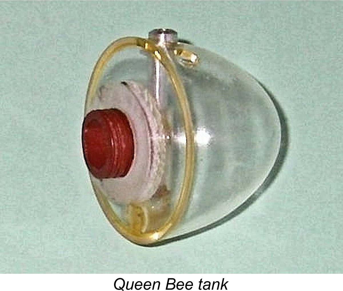
Admittedly, for conservation reasons I had to make these measurements with the engine still assembled, but they can’t be far out. I'm very experienced at taking measurements in this way, and my figures are averages of numerous measurements, all of which were very close to each other. My displacement figure is actually more reflective of the engine’s nominal .24 cuin. displacement than the figure on the box, which implies a nominal .25 cuin. displacement. These figures actually make a good deal of sense in another key respect. During the period in question, precision engineers in the British Commonwealth tended to produce their designs in fractional increments of 1/32 in. rather than decimals or metric units. The measured figures for the Queen Bee 24 correspond to nominal design dimensions of 11/16 in. and 21/32 in. respectively. However, despite commonly using this The Queen Bee 24 was a more or less conventional plain bearing crankshaft front rotary valve (FRV) spark ignition engine of its era. However, it did display some unusual constructional features. The light alloy cylinder head was an internally-threaded item which was seemingly screwed down really hard onto an externally-threaded spigot at the top of the meehanite cylinder before the fore-and-aft cooling fins were cut. Only in this way could their correct alignment relative to the engine’s porting have been assured. The measured compression ratio was a perfectly rational 7:1. The cylinder itself was held down by only two nuts which fitted fore and aft into the cylinder’s lowest cooling groove and engaged with a pair of short steel studs protruding upwards from the upper crankcase deck through the cylinder's location flange. A somewhat awkward assembly, it must be said. However, it did have the desirable effect of discouraging idle tampering by owners. The engine’s other unusual feature was its tank. This was a The tank's other noteworthy feature was the filling system. The tank was internally equipped with a vertical plastic tube which enclosed a lightly spring-loaded aluminium alloy plunger. The idea was that the tip of the filling syringe or other fuelling device depressed the top of the plunger to allow fuel to flow into the tank. When the filler unit was withdrawn, the plunger rose under spring tension to close the hole, leaving only a pin hole opening to permit the entry of air as the level in the tank went down. All very elegant and ingenious, but a bit on the complex side. It was the assembly of these tanks which was the major task assigned to young Hans "Johnny" Edwards. He did a nice job! The rest of the engine was basically conventional. The needle valve assembly consisted of a standard spraybar which engaged with a typical brass split thimble. The thread was 5-40 UNC - a pretty standard thread for North American engines. It's actually a very close match for a British 1/8-40 Whitworth thread. The needle itself was a straight steel component which was bent at its outer end to create a handle for adjustment. A screw-in backplate was used at the rear. The illustrated example weighs in at 175 gm (6.17 ounces) complete with plastic tank and plug. The tank and fuel tubing together account for only 6 gm (0.21 ounces) of this. When describing a spark ignition engine, an important additional parameter which needs to be quantified is the dwell period provided by the engine’s timer. This is the angle of crankshaft rotation during which the points are closed and hence in direct electrical contact with each other, thus supplying current to the ignition coil's primary circuit. I've discussed this parameter more fully in my separate article on spark ignition engine operation. Since sufficient real time must be provided during each revolution to ensure full electro-magnetic saturation of the coil before the points open to trigger the spark, the dwell requirement varies from engine to engine, the main factor being operating speed. A relatively slow-speed unit like a Brown Junior, Atom .099, Bunch, Elf or even an early Ohlsson can operate successfully with a relatively short dwell period of 50 – 60 degrees or even less. A short dwell period conserves the life of the flight batteries, since it minimizes the proportion of running time during which the points are closed and current is flowing to the coil from the batteries. However, it also makes the engine more susceptible to ignition problems caused by point "float". In addition, it limits the maximum speed at which the engine can be run because at higher speeds there's insufficient real time for the coil to become electro-magnetically saturated, as it needs to be to provide a good hot spark. In the case of the Queen Bee 24, the very well-made timer was of the conventional enclosed pattern as seen on many spark ignition engines of the era. Direct measurement confirms that the dwell period provided by this timer is of the order of 50 degrees. Such a relatively short dwell period suggests that the engine was not expected to operate at very high speeds. However, it also means that flight battery life should be well conserved. The tension of the leaf spring that closes the points is relatively high, meaning that float should not be an issue at the kind of speeds which might be expected. Most (but not all) of these engines bore serial numbers which were neatly stamped onto the front face of the crankcase. The un-numbered examples of the 24 are the early ones. In his interesting but frequently inaccurate book "Collector's Guide to Model Aero Engines", the late O.F.W. "Peter" Fisher included a photograph of incomplete Queen Bee .24 no. 0038. My own illustrated example carries the number 0050. These are the only numbers presently known to me. It seems almost certain that the total number produced fell short of three figures - by the time that engine no. 0102 appeared, the 24 had been replaced by the 29. The standard of the engine’s construction is extremely high. The most exacting model engineer would be proud of having produced a one-off unit of this quality. Queen Bee 29
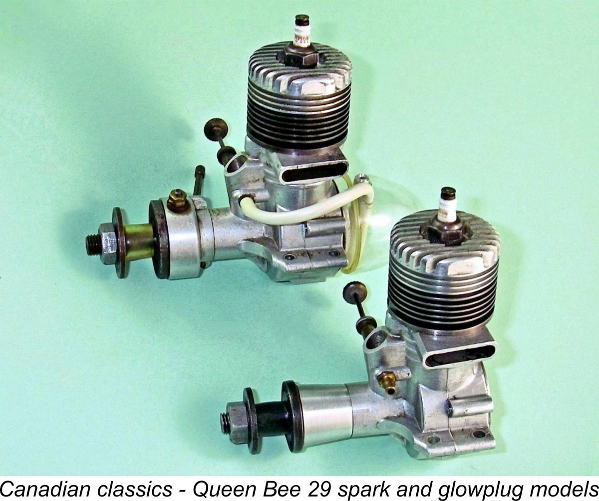
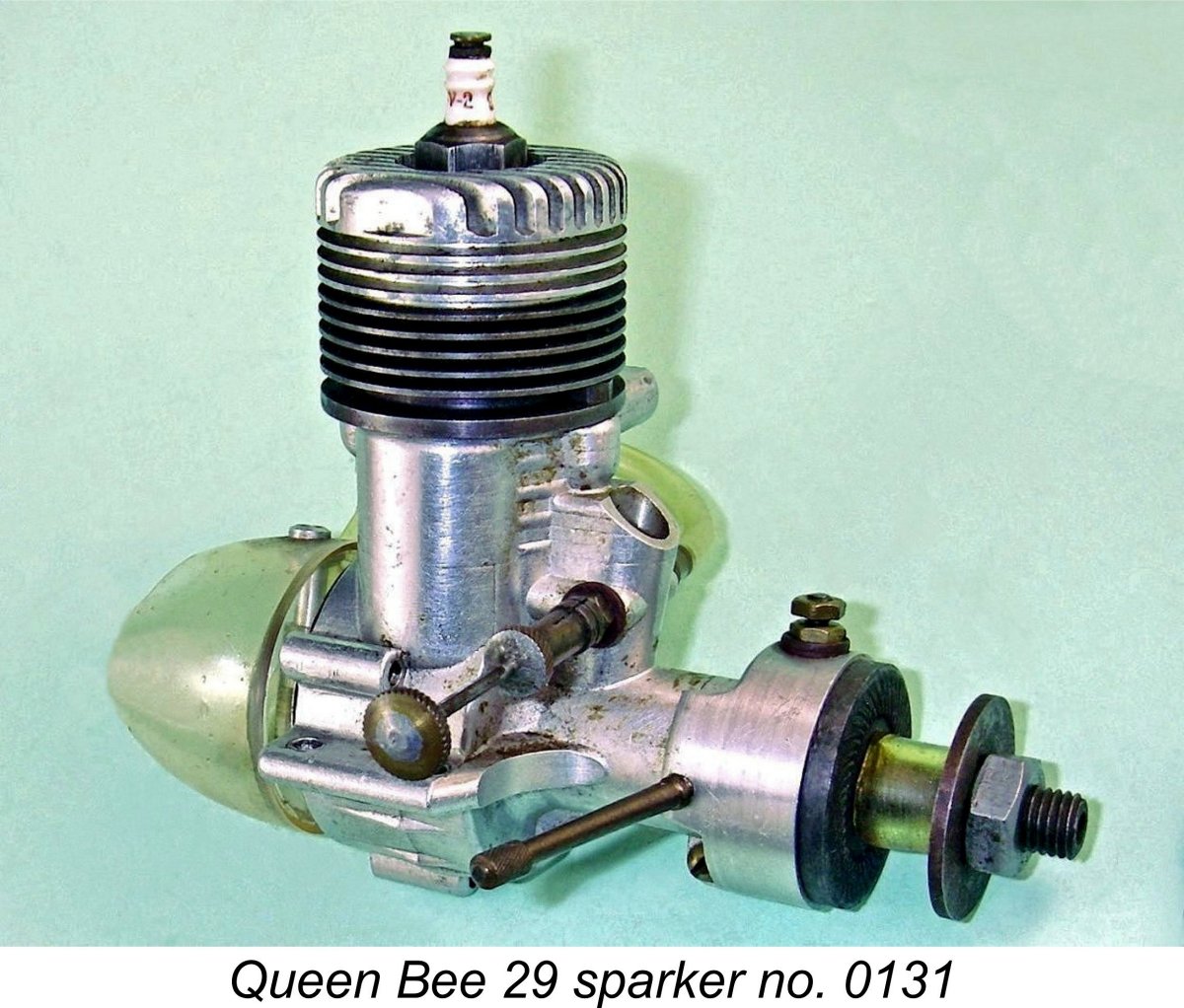
The resulting engine was known as the Queen Bee 29. Previous writers have all cited its displacement as 0.297 cuin. (4.87 cc). However, once again I have been unable to confirm these figures through direct measurement of my own two examples. Repeated measurements (admittedly with the engines still assembled) consistently yield average bore and stroke figures of around 18.25 mm (0.719 in.) and 17.46 mm (0.687 in.) respectively for a calculated displacement of 4.57 cc (0.279 cuin.). Once again, these figures imply a design which was drawn up using fractional dimensions, in this case 23/32 and 11/16 in. In other words, both bore and stroke appear to have been increased by 1/32 in.
The same timer and cam grind were used, giving the same relatively short 50 degree dwell period. However, I’d be prepared to bet that the Queen Bee 29 which powered Al Salonen’s record-breaking 100 mph model illustrated at the left was well tweaked, including the creation of an extended dwell period through a cam re-grind. It was likely also running on methanol fuel, perhaps even with some added nitro. I'm extremely grateful to Hans Edwards for preserving and sharing this historic image. As noted above, the Queen Bee 24 and 29 look very similar, to the point that they have often been confused. Without taking actual bore and stroke measurements it’s a bit tricky to tell one from the other The most easily observable points of distinction are the mounting lugs – those on the 24 only extend to the front of the crankcase, while those on the 29 are extended forward onto the main bearing housing. Careful inspection of the attached comparative image at the right should make this clear. In addition, the cylinder head on the 24 has a rounded profile, while that of the 29 has a basically square profile. The lowest cooling fin on the 24’s cylinder has a slightly reduced diameter, while all fins on the 29 have the same diameter. The bent outer end of the 24's needle has been replaced on the 29 by a knurled brass disc to facilitate adjustment. Finally, the bypass passage on the 29 is visibly somewhat larger. Both models carry serial numbers stamped onto the front of the crankcases. As stated earlier, no serial numbers above 0050 are presently known for the 24, although they almost certainly went somewhat higher. For the 29 model David Axler reported owning engine nos. 0102, 0115 and 0116. My two examples of the 29 carry numbers 0118 and 0131. Reportedly the numbering sequence for the 29 went up to around 0200, after which further examples were un-numbered. More serial numbers are definitely required to clarify this point. In particular, it would be really useful to have confirmed numbers which provide a closer indication of the point in the numbering sequence at which the transition from the 24 to the 29 occurred. If you are able to supply any such numbers, please get in touch!
Needing to check the new system through an actual running test, I proceeded to set up Hans Edwards' old Queen Bee 29 no. 0118 to give it a try. Running on a blend of 3 parts Coleman camp fuel (white gas) to 1 part of SAE 60 AeroShell 120 mineral oil, it didn't let me down, starting on the third flick after its 70 year layoff and running flawlessly throughout. After spending some time becoming conversant with the finer points of spark ignition engine adjustment, I was able to get the Queen Bee spinning its APC 10x6 test prop at a comfortable 8,600 rpm, implying an output of around 0.240 BHP at that speed. I consider this to be a pretty good performance for a 1946 .279 cuin. sparkie running on white gas. The engine was running absolutely smoothly at this speed, confirming that its timer was still functioning very well despite its relatively short dwell period. Even so, I doubt that the engine as it stands would run much faster without some extension of that dwell period. I didn't try to push it any further on this occasion. Subsequent restarts showed that the very easy starting on the first attempt was no fluke - the engine continued to start almost immediately every time. Overall, I was thoroughly impressed both with its performance and its quality of construction. Queen Bee 29 Glowplug
The Queen Bee 29 glowplug model need not detain us long, since it was in effect nothing more than a standard 29 spark ignition model on which the timer was replaced with a tapered aluminium alloy press-on sleeve. In addition, a smaller-diameter prop driver was used. The engine’s working dimensions were of course unchanged, but the weight was reduced to 166 gm (5.85 ounces) as a result of the omission of the tank and timer. The plastic tank was omitted since it would not have withstood use with glow fuel, so poor Hans Edwards was out of a job! On some examples, the internally threaded recess in the backplate for the tank mounting spigot was also omitted, although my example retains that recess. Presumably Al Salonen was using up left-over spark ignition backplates which were already on hand. This model was produced in relatively small numbers. It is far less commonly encountered than the spark ignition version. That said, examples may crop up that are owner-converted sparkers. Some of these are easy to spot, since they carry serial numbers, which original At the same test session at which I tried the Queen Bee 29 sparker as described earlier, I also ran an abbreviated test on the glowplug version, just for comparison. Using a fuel containing 15% nitro (all that I had on hand at the time), the engine proved to be an instant starter and a fine runner. This example is seemingly little used and hence still rather tight, evidently requiring some careful running-in to bring out its best performance. Even so, on a few brief spot checks it was found to be spinning the same APC 10x6 prop at a cool 9,500 rpm, implying an output of around 0.321 BHP at that speed. Quite a bit faster than its spark ignition companion, but one must remember that it was running on the inherently more powerful methanol base fuel with the added benefit of that 15% nitro. It's likely that on straight FAI fuel the two engines would deliver quite similar performances. When time and opportunity coincide, I hope to test this assertion at some point in the future. Queen Bee 60 Spark and Glowplug
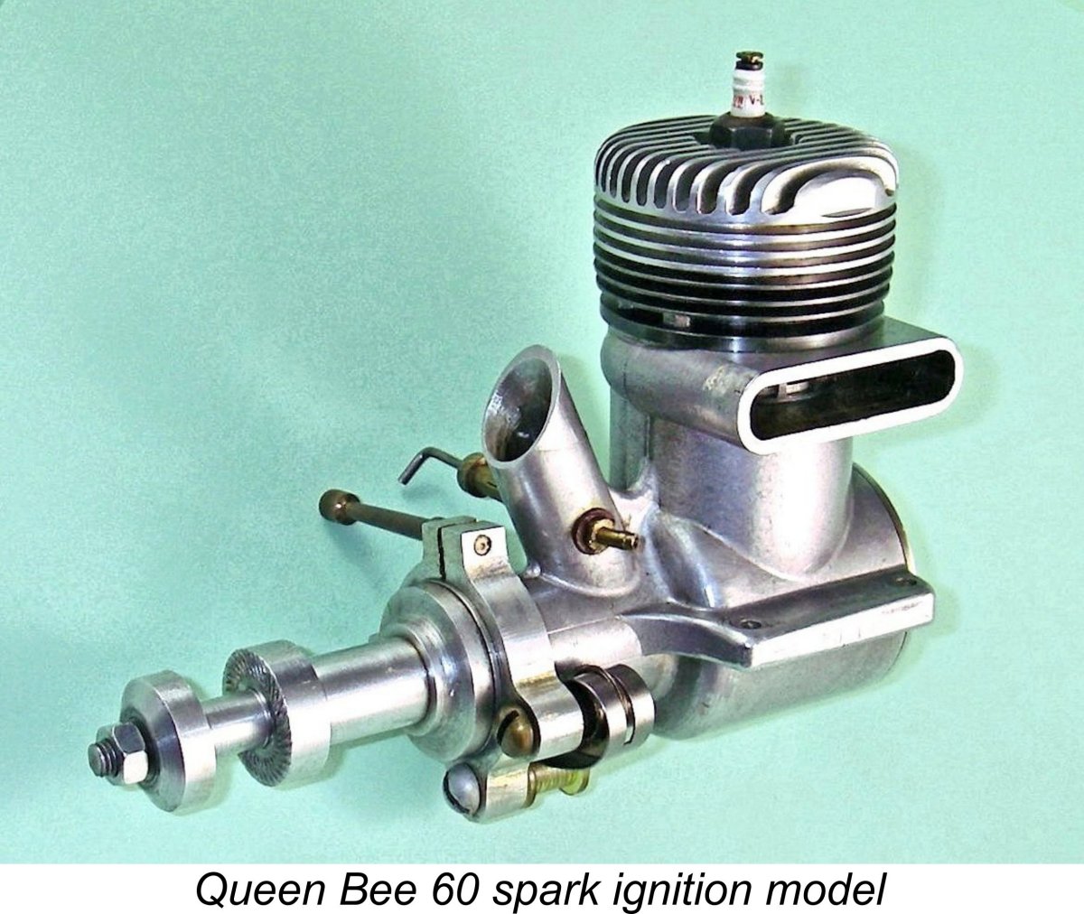
However, two experimental models that have somehow survived are the prototype Queen Bee 60 models which were made in both spark ignition and glowplug versions. Thanks to the kindness of my friend Peter Rathke, both of the known surviving examples are in my possession today – they’ve come back home! The only apparent differences between the two units are the omission of the superbly-made automotive-style timer from the glowplug version, along with the use of a somewhat different prop mounting assembly and a simplified front housing which lacks the necessary aperture to allow the cam follower to contact the cam surface. In all other respects, the two models appear identical.
Measured bore and stroke figures for the two engines are exaggeratedly over-square at 25.4 mm (1.00 in.) and 19.905 mm (0.75 in.) respectively for an actual displacement of 9.65 cc (0.589 cuin.) and a bore/stroke ratio of 1.33:1. Unmistakable signs of Dooling influence, methinks! The very short stroke accounts for the rather squat appearance of the engines. They are relatively light for racing models of their displacement, tipping the scales at 398 gm (14.04 ounces) for the sparker and 376 gm (13.26 ounces) for the glow.
The engine as-is would certainly run just fine on glow-plug ignition – indeed, all indications are that it has done some running in the past. An alternative possibility is that it was originally assembled as a fully functional spark ignition unit, but subsequently broke its original shaft. If so, the broken shaft was replaced with a glow component to restore the engine to service. We’ll never know …….. The quality of construction of these two engines is absolutely top class. The compression seal in both examples is outstanding. Both units have clearly been mounted and have done some running, but both remain in superb mechanical condition. No model engineer could do a better job on an individually-constructed one-off.
The survival of these partly-finished components is fortuitous in that it allows us to understand the way in which the cylinder and head engaged with each other. The cylinder was provided with a protruding externally-threaded spigot at the top, onto which the internally threaded cylinder head was screwed down. I think it's a reasonable assumption that all models were constructed in a similar fashion. I'd also suggest that such an assembly was most likely sealed with some kind of compound both to prevent gas leakage and to discourage either accidental or intentional unscrewing. Conservation issues In the interests of conservation, several points should be mentioned here. Firstly, none of these engines should be dismantled without really good cause. Any desire to “just have a look” should be strongly resisted! Removal of the backplate probably can’t do much harm, but please use the appropriate pin spanner to avoid marring the component.
In addition, there’s the issue of the screw-on cylinder head with its carefully-aligned cooling fins. If that alignment were to be disturbed, it would likely be very difficult indeed to re-establish both the correct cylinder head alignment and a good head seal when re-fitting the head. Moreover, there's also the previously-noted probability that some kind of sealing compound was used when assembling the engines, which would make removal well-nigh impossible in any case. Definitely best left alone ……..the absence of any provision for obtaining a purchase on the heads for dismantling and re-assembly strongly implies that the maker wished to discourage any such activity.
Alternatively, some owners have enlarged the rear mounting holes in the beam mounting lugs to allow bolts to be inserted at an angle to clear the radial mount lugs. These are very understandable modifications, but please don’t do either! Instead, use studs which enter the beam mounting holes from below and deploy separate nuts on top of the beam mount lugs to secure the engine. Mounting in a test stand is of course unaffected by this issue. The other key point of which to be keenly aware is that if you’re ever lucky enough to find a spark ignition example which retains its screw-on plastic tank, you need to know that those tanks become incredibly brittle with age, shattering with almost no provocation. Handle them with the very greatest care, and do not attempt to run the engine with the tank fitted!! Conclusion Production of the Queen Bee engines was quite small – probably no more than 400 units of all types were constructed in total. However, all of them were built to the very highest model engineering standards. The surviving examples stand as a testament to the skill of a talented and dedicated maker who unquestionably placed quality before profit, hence sadly finding himself unable to survive as a model engine manufacturer in the post-WW2 mass-production era. These engines are by no means common today, but they haven’t quite attained the status of unobtanium – their quality ensured that they didn't break or wear out, so people tended to keep them. Consequently, examples do surface from time to time. If you ever get the chance to acquire one of these fine powerplants, I’d definitely recommend giving it serious consideration! _________________________ Article © Adrian C. Duncan, Coquitlam, British Columbia, Canada First published May 2019 |
 In this article, I’ll present a summary of the only model engine range ever to have been commercially produced in my own back yard on Canada’s West Coast – the early post-WW2 Queen Bee engines from Vancouver, British Columbia, just a few kilometres from my present-day home in Coquitlam. These are not to be confused with the far later Cox Queen Bee .074 glowplug unit which appeared in 1987 from a completely unrelated source. There's no connection whatsoever beyond the name.
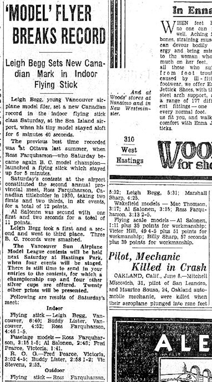
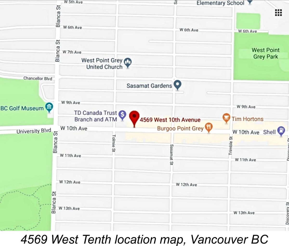
 No traces remain today of Al Salonen's former premises. The entire commercial 4500 block has been extensively remodelled, with the numbers for the reconstructed commercial buildings which now occupy the east half of the block ending at 4545. It appears that no. 4569 was a victim of a later eastward expansion of the Safeway parking lot. Even the Safeway store itself is now closed, with re-development of its site (including the location of Al Salonen's former premises) just getting underway at the time of my visit in April 2019.
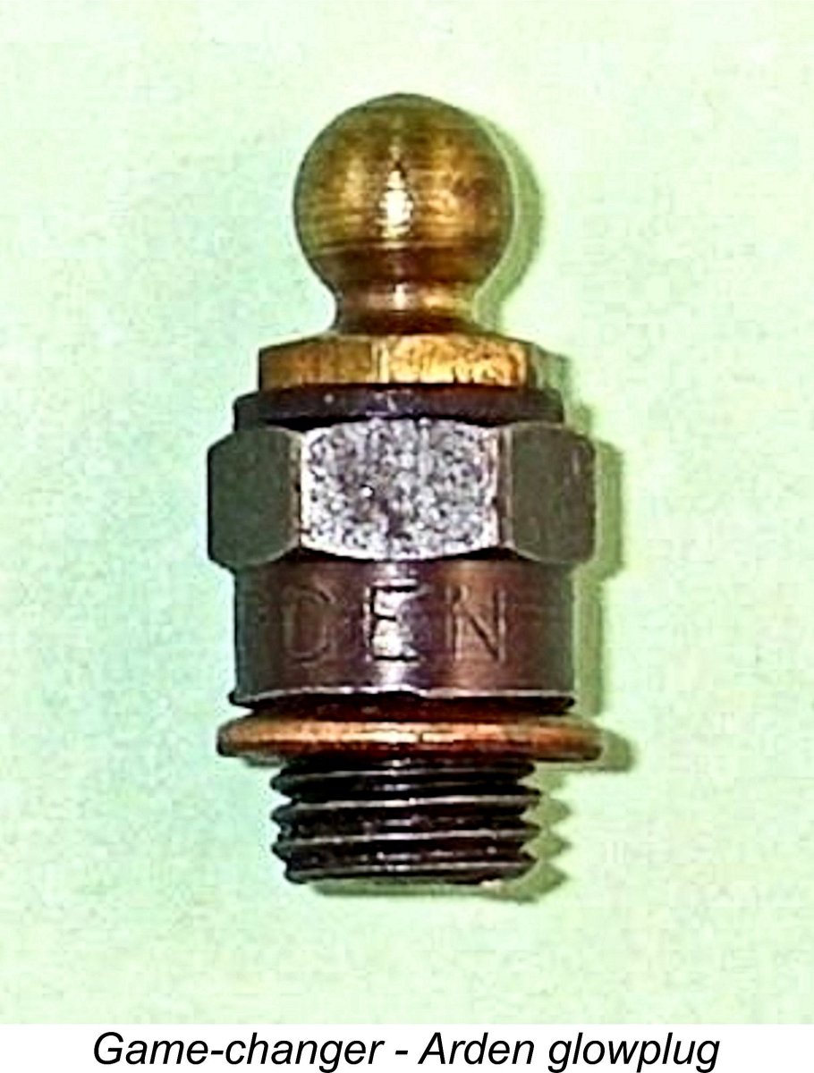
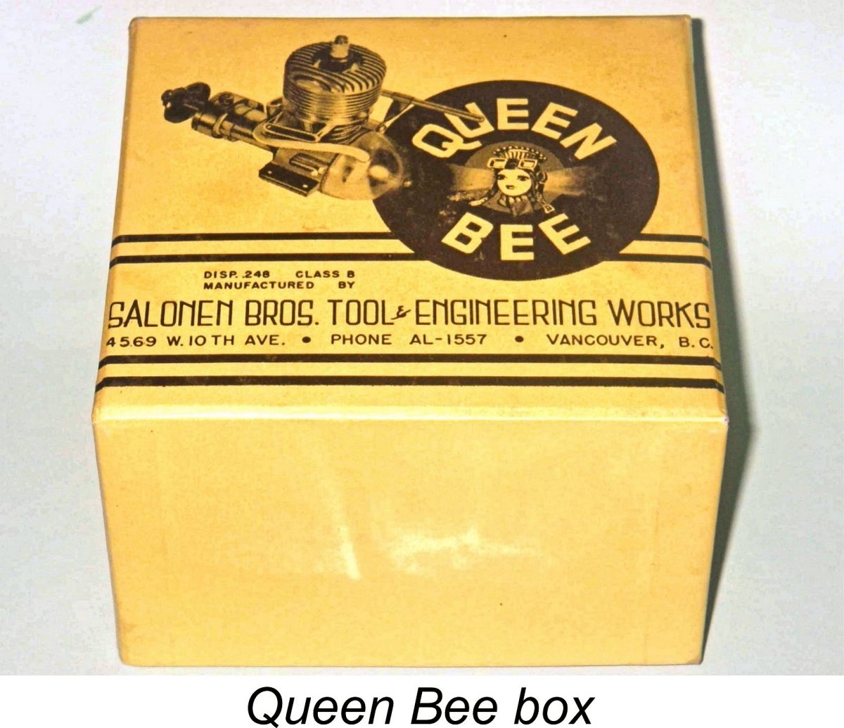 The engines were packaged in very sturdy and clearly-labelled yellow boxes. These boxes were all labelled for the firm’s original offering, the Queen Bee 24 – the nominal displacement of that model was prominently featured. They were too small to contain the later .60 models, but these were never marketed commercially in any case. Interestingly enough, the boxes were never updated to reflect the later 29 models - the same box was used for those engines also.
 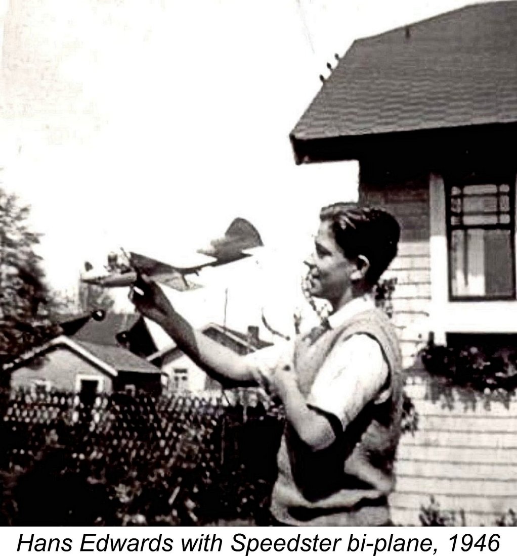 This shared interest gave rise to a circumstance which actually represents a very distant but nonetheless real connection with my own latter-day modelling activities. Both Al Salonen and Hans "Johnny" Edwards were active members of the Vancouver Gas Model Club (VGMC), one of Canada’s longest-established model clubs, having been formally established way back in 1935. The club is still going strong at the time of writing (2024), and I’m a paid-up member! It was in fact our latter-day Club President, the late Bruce Duncan (no relation!), who very kindly put me in touch with Hans Edwards back in 2019.
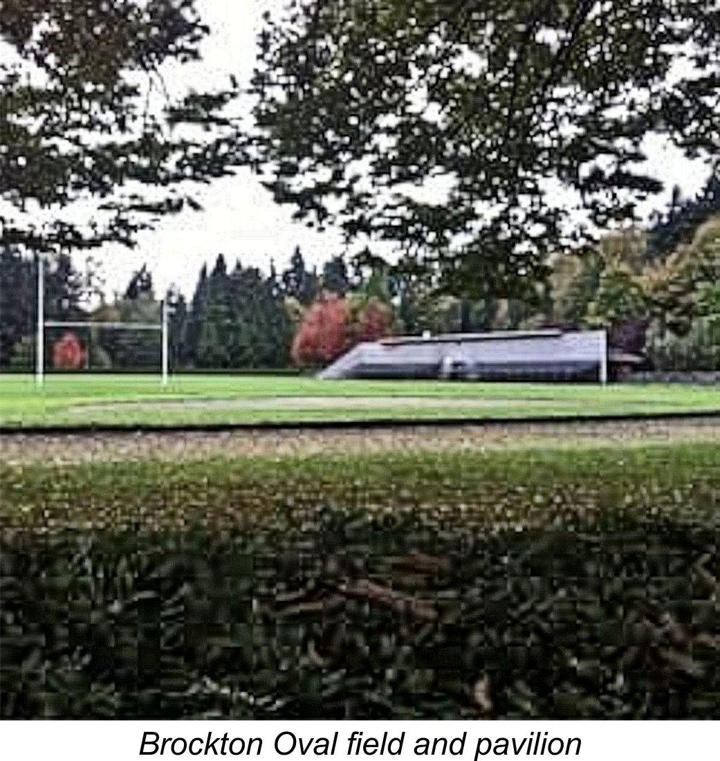
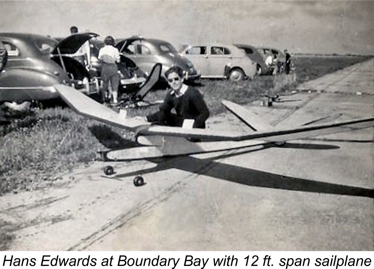 During the same period, the members of the VGMC also flew free flight models. Much of this activity took place a little to the south of Vancouver near Boundary Bay at the decommissioned wartime military airfield formerly associated with Canadian Forces Base Ladner. After a lengthy period of mixed use (including model flying and motorcycle rider training), this WW2 airfield was finally re-opened for general full-sized aviation use in July 1983 under the name Boundary Bay Airport. It remains in use today (2024) as a light plane and flight training field. It is actually Canada's busiest general aviation airport and the country's fifth-busiest airport overall based on the average number of daily flight movements. Consequently, it is no longer available for model flying.
  Hans Edwards’ personal association with Al Salonen ended in 1951 when, after a period of attending UBC, he went to England to work for a couple of years at the
  The first model to appear from Al Salonen’s workshop was the Queen Bee 24 spark ignition unit which made its debut in 1945. The displacement of this unit was given on the box as .248 cuin. (4.06 cc), but repeated measurements taken from my own example consistently yield bore and stroke figures of around 17.46 mm (0.687 in.) and 16.67 mm (0.656 in.) respectively for an actual calculated displacement of 3.99 cc (0.244 cuin.).
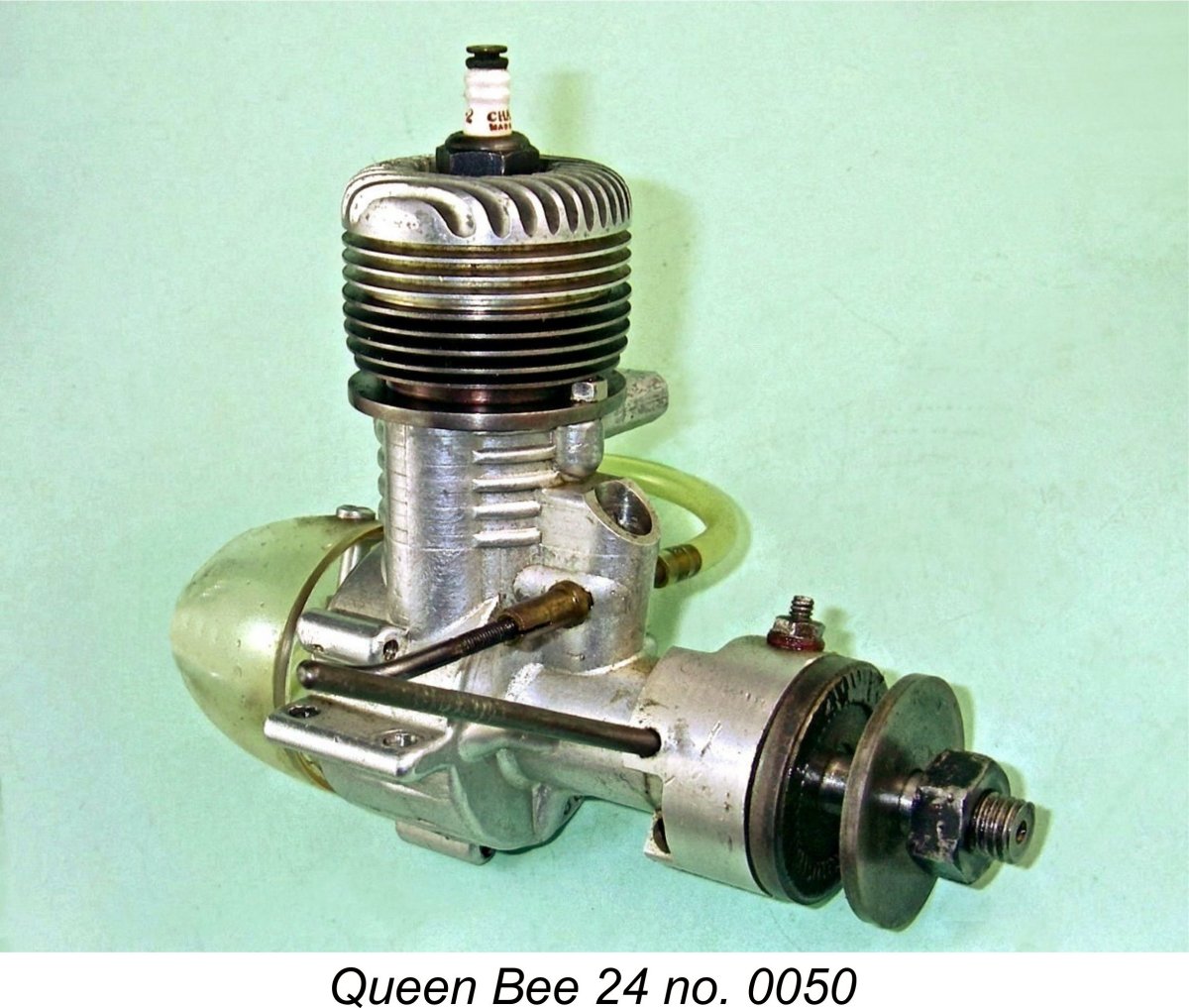
 After a certain number of examples of the Queen Bee 24 had been manufactured, Al Salonen decided that a somewhat higher performance model built up to the full Class B specification was required. This resulted in the 1946 replacement of the Queen Bee 24 by a revised model having a somewhat greater displacement. The engine was little changed in its essentials – the increased displacement was obtained by an increase in both the bore and stroke of the same basic design.
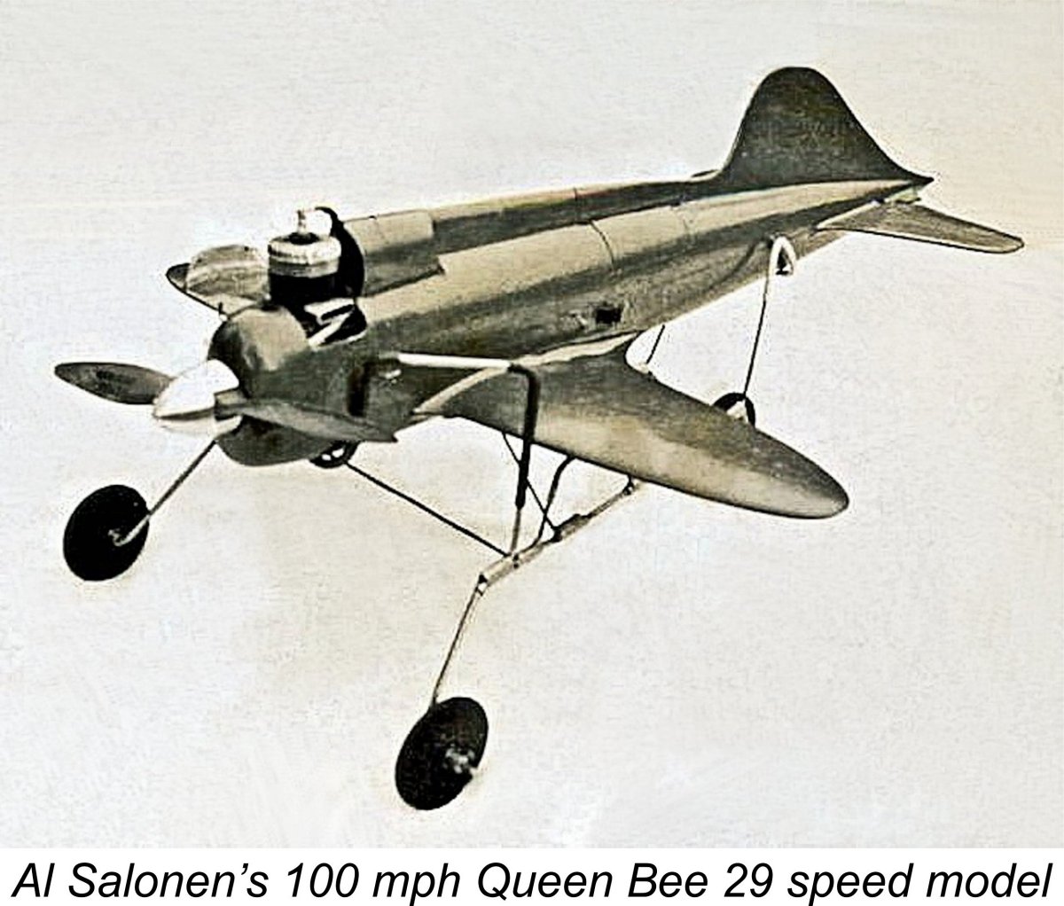 The construction of the Queen Bee 29 was identical to that of the 24, so there is no need to repeat that description here. The engine’s weight with tank and plug was very little affected – the new model weighed in at 179 gm (6.31 ounces) complete with plug and tank. Perhaps the most notable change was an increase in the measured compression ratio from 7:1 to a somewhat more sporty 8.5:1. Clearly Al Salonen was going after a bit of a performance boost.
 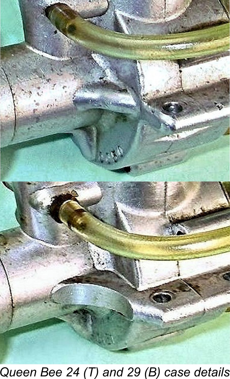 across the room. Even close up, the problem is compounded by the fact that apart from their serial numbers, neither the Queen Bee 24 nor 29 bear any marks of model identification. The 29 has very slightly larger cylinder and crankcase external diameters, but that’s not much help unless you have both models side by side. Even then, it’s not immediately obvious because the differences are not great.
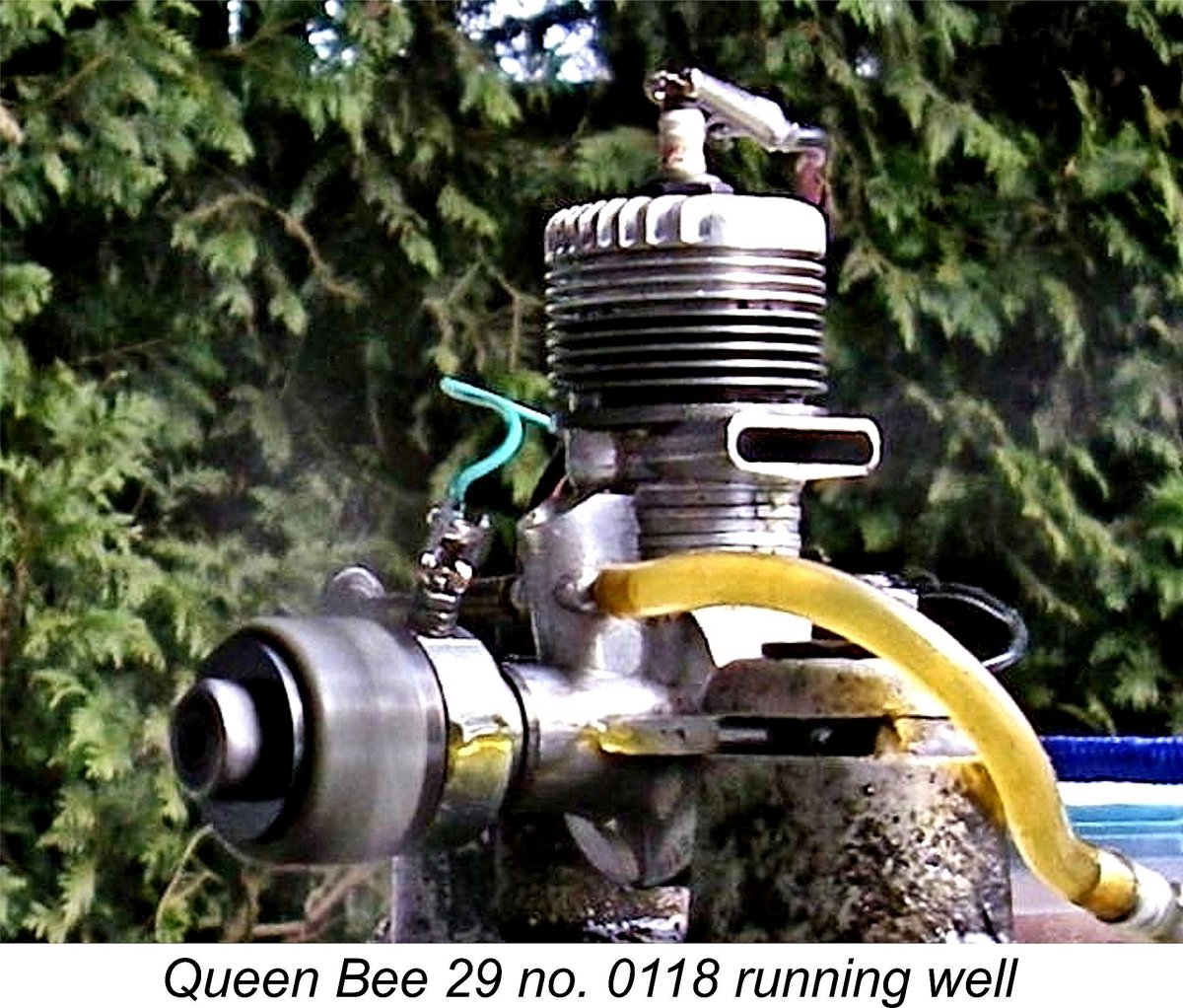 At the time when I was researching this article, I had just completed my work on the assembly of an ignition support system for bench-testing spark ignition engines. That very successful project is summarized in a
 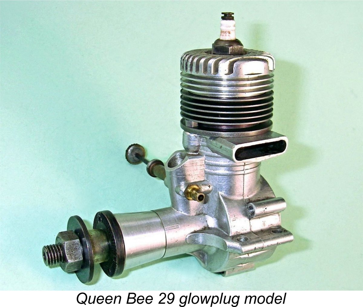 The final commercial offering from Al Salonen was a glowplug version of the Queen Bee 29. This model made its appearance in the first half of 1948 shortly after Ray Arden’s late 1947 introduction of the commercial miniature glow-plug - Al Salonen was quick to appreciate the significance of that event.
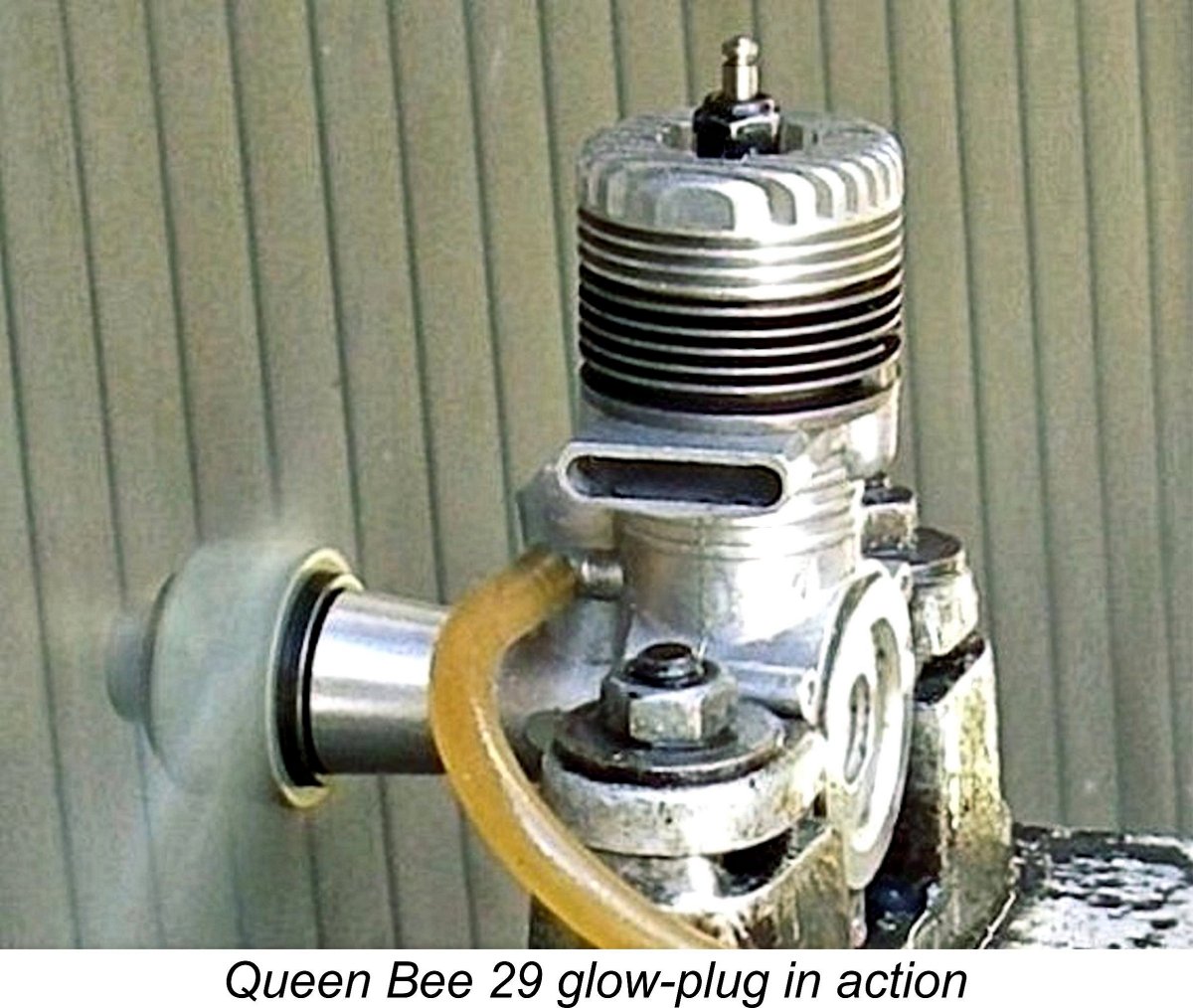
 As previously noted, Al Salonen seems to have enjoyed trying different concepts, producing a number of experimental prototypes along the way. Among these were some half-dozen diesel variants of unrecorded specification. None of these reached the production stage, and there are no presently-known survivors today. They may have ended up in Burrard Inlet along with the rest of the Queen Bee project!
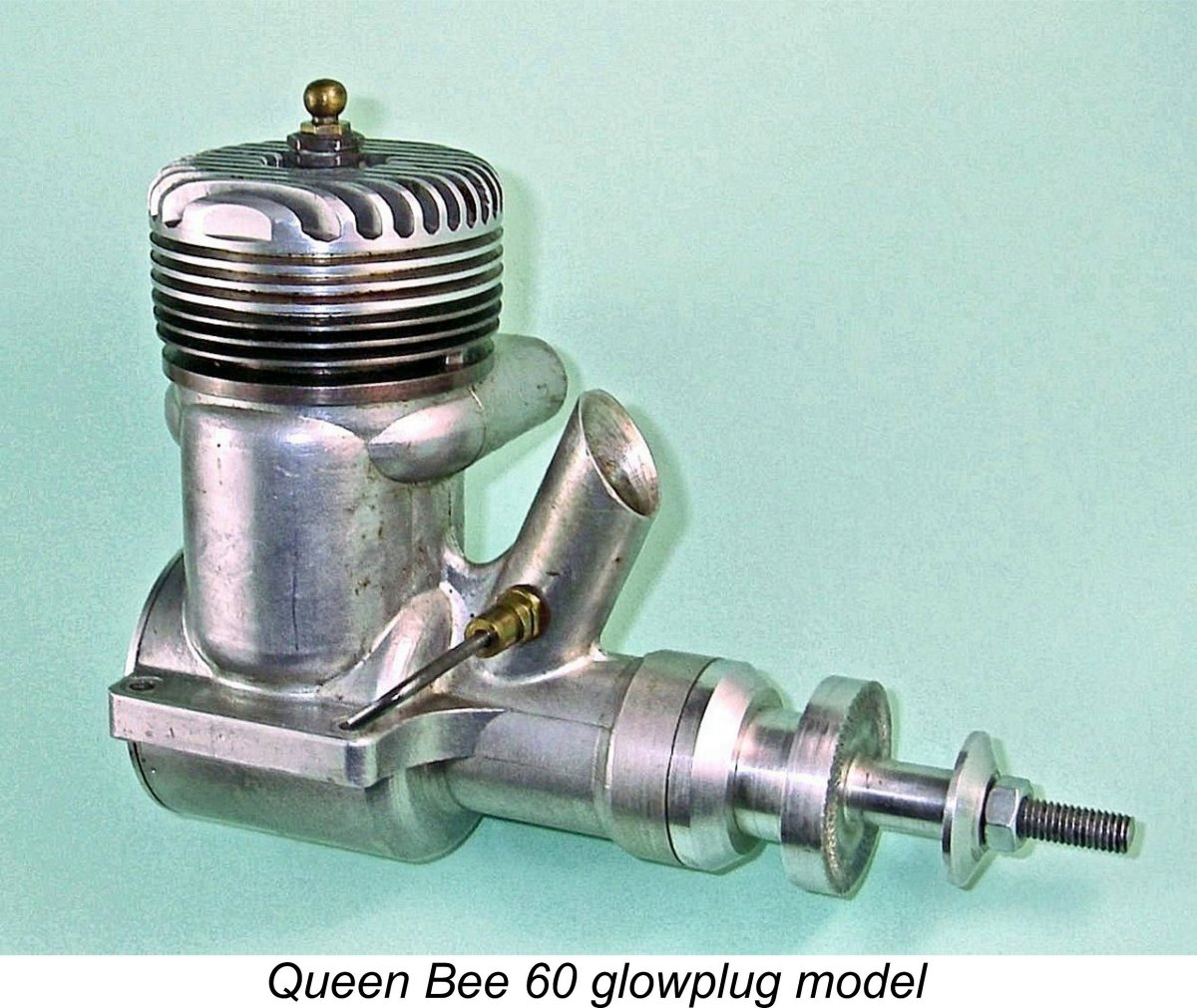 The Queen Bee 60’s were clearly intended to operate as racing engines. Setting aside their use of crankshaft front rotary valve (FRV) induction, both units display most of the typical racing engine features of their day, including short-stroke internal geometry, cross-flow loop scavenging, a ringed aluminium alloy baffle piston, a twin ball-race crankshaft, a big-bore intake venturi (9.5 mm/0.375 in.), a surface jet needle valve assembly and a very high compression ratio. In my opinion, Al Salonen went a bit over the top in the latter respect, because both engines sport carefully measured compression ratios of no less than 13:1 – about the highest of my acquaintance. I wouldn’t want to try running the sparker on gasoline …………… straight methanol/castor fuel and a cold plug are definitely indicated for both examples.
  The fact that these engines were still at the prototype stage is confirmed by the fact that although the illustrated spark ignition example was assembled as such in all respects, including the fully functional timer and modified front housing with cam access aperture, Al Salonen never got around to adding the cam to the shaft, evidently using a standard glow shaft in assembling what was in effect a mock-up. Consequently, the timer’s moving point doesn’t move! This may imply that the glow-plug version was developed first and the sparker was an afterthought which Al was in the process of trying out.
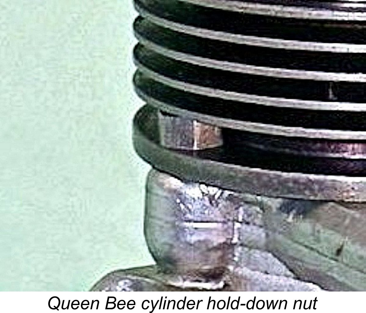 The cylinder is quite another matter! For one thing, the meehanite cast iron fins are easily broken or distorted. For another, the cylinder is retained by two nuts (or four in the case of the 60’s) on studs located fore and aft which act directly upon the cylinder installation flange located immediately above the exhaust port. The nuts are thus necessarily positioned inside the lowest cooling groove – shades of the original Allen-Mercury 25. Even using the appropriate tool and proceeding in progressive matching stages, their removal and re-installation is a royal pain which can easily cause damage to the readily-distorted cylinder.
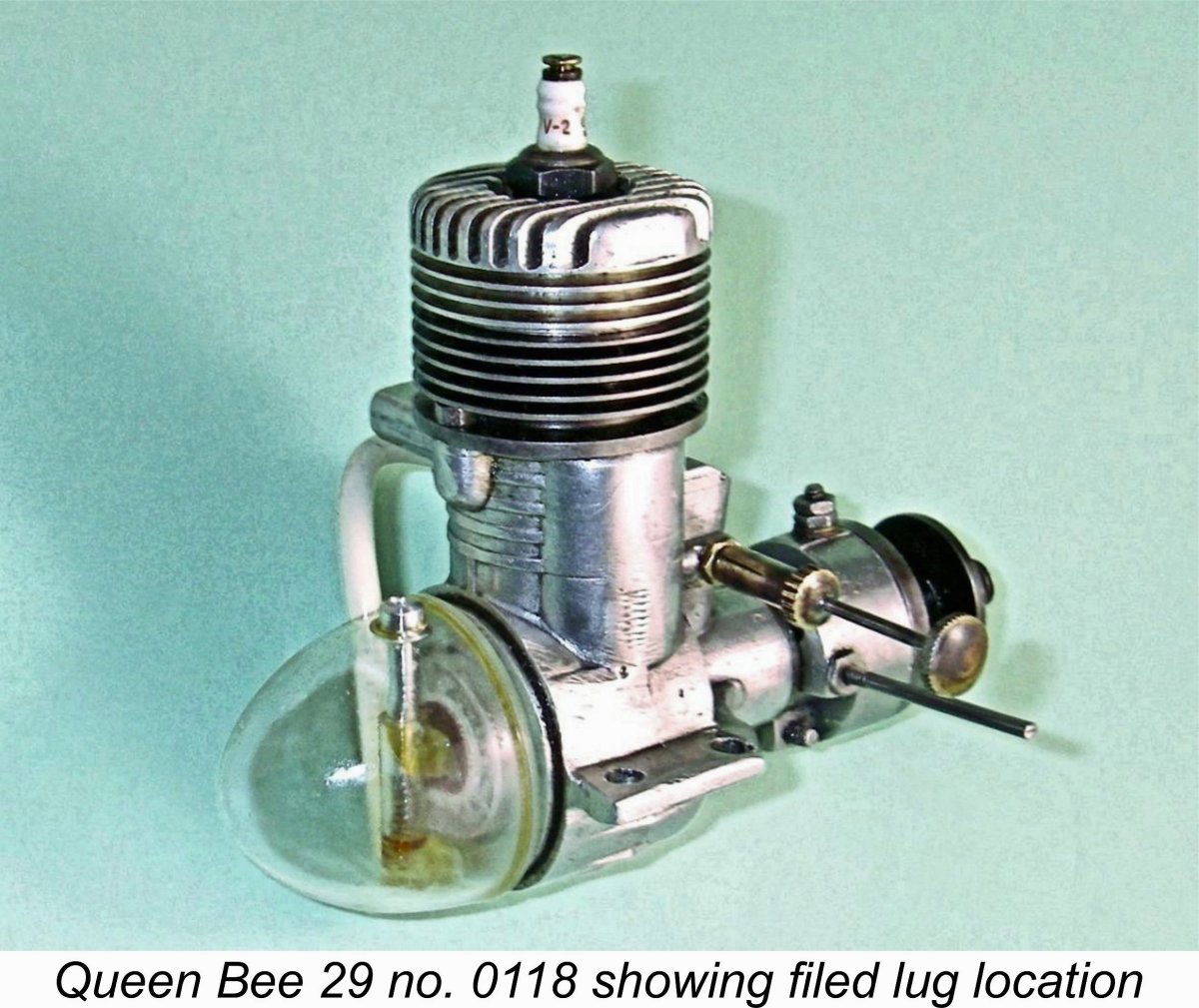
| |