
|
|
Calculating Model Engine Displacements
It’s clear that one of the first steps in the secure identification of an engine must be the determination of its displacement. In this very brief article, we’ll review how this is done. As a first step, it seems worthwhile to deal with one of the most common examples of confusion in terminology – “displacement” versus “capacity”. The attached illustration extracted from "Model Aero Engine Encyclopaedia" should help to clarify this topic.
By way of contrast, the capacity of the cylinder of an engine is the total volume of gas in the cylinder above the piston crown when the piston is at bottom dead centre. It should be obvious that this includes not only the piston’s swept volume V but also the combustion chamber volume v remaining above the piston when it reaches top dead centre. Consequently, an engine’s capacity (V+v) will always exceed its displacement. In the case of a variable compression diesel in which v can be altered at will, this figure is not even fixed, hence being useless as a definitive descriptor of an engine’s size. The purpose of the above explanation is to demonstrate that when we refer to an engine’s size we are always referring to its displacement. Unfortunately, many earlier writers on the subject of model engines, notably those whose work appeared in the British modelling media during the “classic” era, referred to an engine’s “capacity” when what they were really referring to was its displacement. Time to end any such residual confusion …………….
The first step is simple – we measure the bore by establishing the diameter of the piston across its working surfaces. Care must be taken to avoid marring the piston surface, but this is generally not a problem as long as the flat portions of the caliper jaws are employed and only light caliper pressure is used. Of course, the internal diameter of the bore can be measured directly if you have the appropriate measuring equipment. However, a standard caliper applied to the piston generally suffices for the present purpose.
Of course, with a glow-plug or spark ignition unit one can simply remove the plug and use the plug hole as an access point to measure the distance from the top of the cylinder head down to the piston crown at both bottom dead centre and top dead centre. Again, the difference will be the engine’s stroke. A standard engineer's caliper is once again very suitable for taking these measurements with sufficient accuracy for our purpose. Even if dismantling of the engine is not possible (or inadvisable for conservation reasons), there are ways and means by which the bore and stroke can be measured with sufficient accuracy without disturbing the engine beyond perhaps removing the backplate (in the case of a diesel) to measure the stroke. However, the measurement of the bore in this manner does impose some risk of bore or piston damage unless it is very carefully carried out, since it involves the taking of measurements through the exhaust port(s) - not recommended unless you really know what you’re doing. For that reason, it’s always preferable to measure the bore directly, as described earlier. OK, so now we have our measurements – say, B for bore and S for stroke. The next point to keep in mind is the issue of units. The key requirement here is to keep them consistent – either use inches or centimeters for both measurements. If you use inches, you‘ll get the resulting displacement in cubic inches (cuin.), while the use of centimeters will yield a result in cubic centimeters (cc). It will be appreciated that the piston crown sweeps a portion of the engine’s bore that takes the geometric form of a cylinder. The volume of a cylinder is its cross-sectional area times its length. In this case, the crooss-sectional is of course the area of the piston crown, which is defined by the equation π x B2/4, where the Greek letter π (pi) stands for the number 3.142 which is a natural constant defining the relationship of the diameter of a circle to its circumference and area. If we multiply this figure by the engine’s stroke S, we get its displacement. In summary, the displacement of an engine is the result of solving the equation: Displacement = π x B2/4 x S It save a certain amount of fiddling if we simply divide π (3.142) by 4, giving the figure 0.7855. This is the figure that I remember, rather than π! Now all that’s involved is to run the following sequence on your calculator, keping the units consistent: Displacement = 0.7855 x Bore x Bore x Stroke
To work out the engine’s displacement in cubic inches: Displacement = 0.7855 x 0.770 x 0.770 x 0.730 = 0.340 cubic inches. To work out the engine’s displacement in cubic centimeters, we have to remember to divide the figures in millimeters by 10 to convert to centimeters. This merely involves moving the decimal point one place to the left. Having done this: Displacement = 0.7855 x 1.956 x 1.956 x 1.854 = 5.57 cc Of course, once we have the displacement in either set of units, the conversion from one to the other is very simple. Since 1 cubic inch equals 16.387 cubic centimeters, all that is necessary to convert from cubic inches (cuin.) to cubic centimeters (cc) is to multiply the figure in cuin. by 16.387 to get the same displacement expressed in cc. To go the other way (from cc to cuin.), one divides by 16.387 rather than multiplying. However, we generally don’t even have to do this, since almost all calculators now have direct conversion functions. In summary, all that’s necessary when working out an engine’s displacement is to keep the units consistent when taking your measurements and remember the number 0.7855!! _____________________________ Article © Adrian C. Duncan, first published November 2015
|
 It’s not uncommon for a collector to encounter an engine whose identity is uncertain. Moreover, even when the engine’s manufacturer is known, there are many examples of engines from the same maker which look almost identical but have slightly different displacements. The most common examples of this are the fairly numerous 2.5 cc (.15 cuin.) and 3.25 cc (0.199 cuin.) versions of essentially the same engine - the PAW engines are good examples of this. The .049 and .051 cuin. versions of a number of American
  The displacement of an engine is the volume in the cylinder that is swept by the piston crown as it moves from bottom dead centre to top dead centre. The gas that occupys this volume when the piston is at bottom dead centre is necessarily displaced by the rising piston, either by being discharged through an open port or (once all cylinder ports are closed) by being compressed into the combustion chamber above the piston. The volume of gas displaced in this manner must equal the piston’s swept volume, which is designated as V in the attached diagram. Hence the term “displacement” and the term “swept volume” are synonymous – the former term is used purely for brevity.
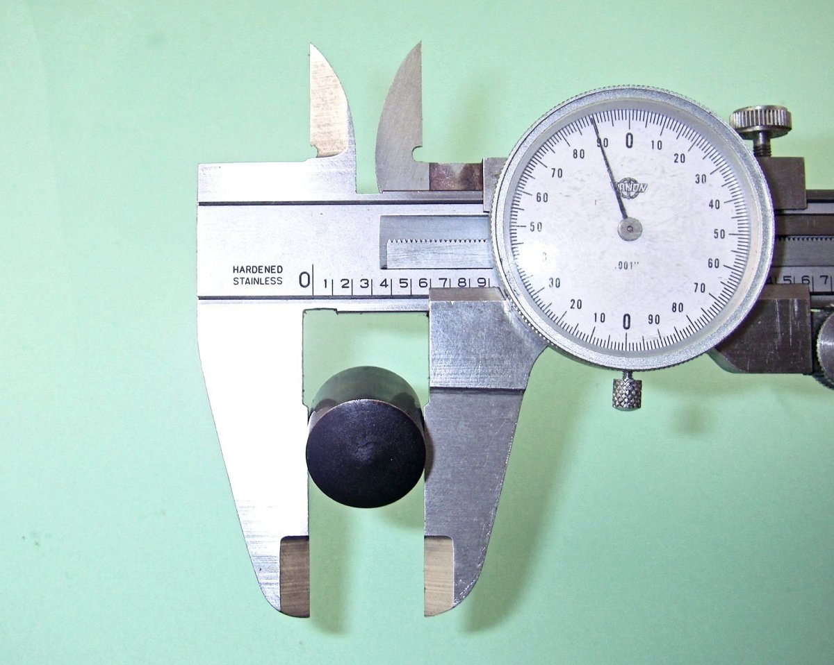 OK, so we have an engine whose displacement we wish to determine. Making such a determination requires that we know both the engine’s bore and stroke. For simplicity, we’ll assume that we are able to take the engine apart for measurement purposes. We’ll also assume that we have a suitable measuring instrument – an engineer’s caliper of the kind readily available at automotive stores and the like will suffice for this purpose.
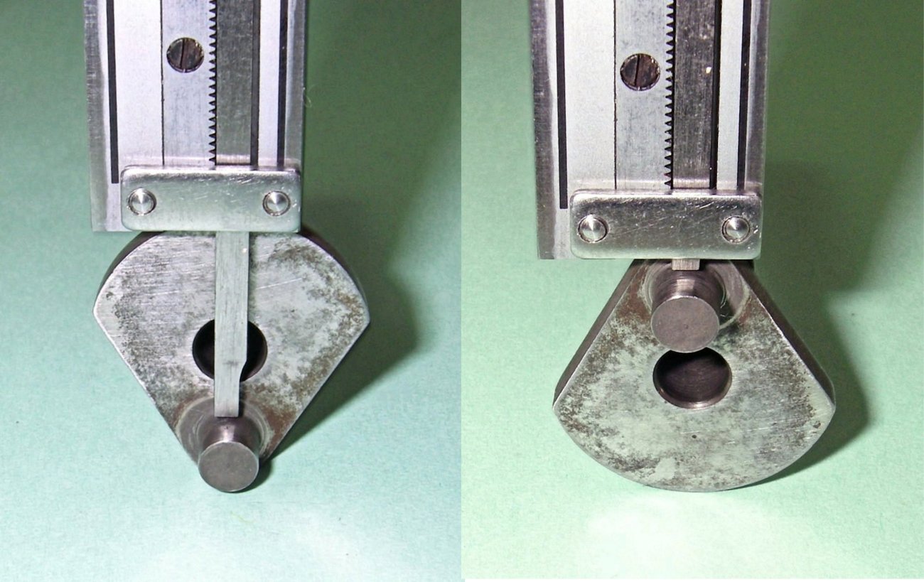 Measurement of the stroke is a little more complicated. The method that I’ve found most convenient with engines having a full disc or segmented disc crankweb is to measure the distance from the uppermost edge of the crankweb to the nearer surface of the crankpin at its nearest and furthest locations (corresponding to top dead centre and bottom dead centre respectively), doing so from opposite sides as shown in the illustration. The difference between these two measurements will be the engine’s stroke.
 Example:
 | |