
|
|
Peter Burford's Miniature Masterpiece – the PB 0.33 cc Diesel
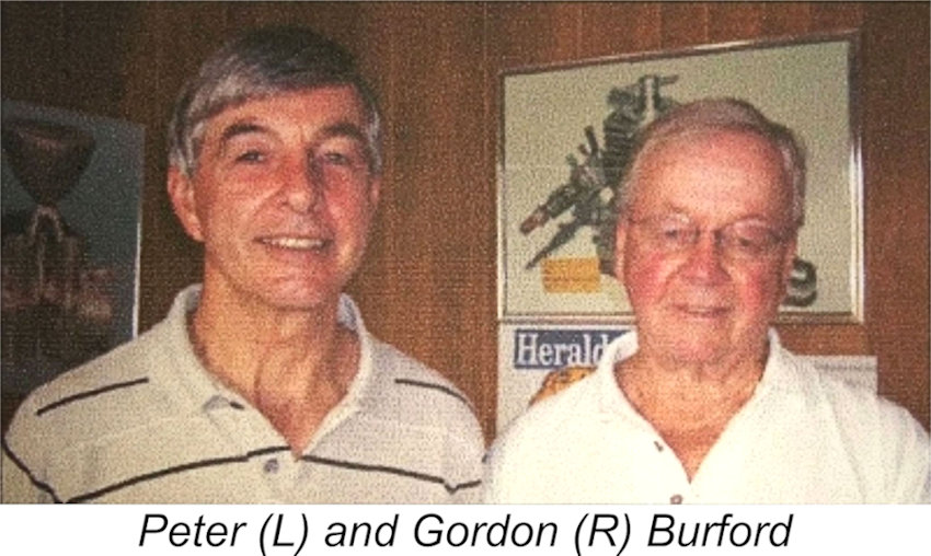
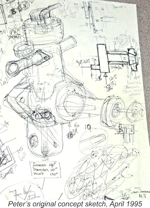
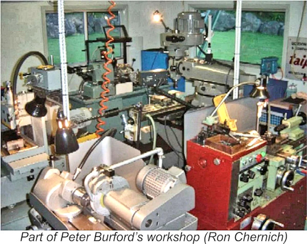
What seems to be less well-known is that from 1960 onward, Gordon was ably assisted by his eldest son Peter, who apprenticed with his father, eventually becoming the Plant Manager of the Taipan operation. Peter stayed with the family business to the end, designing what proved to be the final Taipan model, the superb Taipan 40, along the way. However, as of 1976 it had become obvious that despite offering a world-class product, it was no longer economically viable for Taipan to continue competing in a comparatively small niche market While Peter was operating his die-making and injection molding business on Australia's Gold Coast, he continued to observe his father's ongoing post-Taipan “retirement” activities making various small production-run engines, evidently deciding that it all looked like great fun. Peter never characterized himself as a modeller, although with Gordon for a father the flying of small control-liners and other types while growing up was unavoidable! This experience had inspired a modeller’s passion for small engines which stayed with Peter through the years. Even though he had been part of the decision that saw Taipan manufacture cease in 1976, Peter retained a suppressed desire to build a premium-quality engine in which manufacturing cost considerations would not be allowed to compromise the quality factor. The engine of his dreams would be designed, developed and So Peter knew what he wanted to do, but realized that he'd have to retire first if he was to do it on his own terms! Some people retire, then have to decide what to do with their sudden increase in spare time, while others see retirement as a necessary prelude to realizing a long-held ambition. Peter was one of the latter! I fully endorse his attitude – retirement should be a planned move towards something positive, not a move away from a work situation towards an unplanned future. Naturally, Peter couldn’t retire immediately, but in 1995 he took the first steps down the road which would lead 9 years later to the appearance of the engine of his unfulfilled ambitions. The picture here is Peter's original sketch for his 0.33 cc diesel dated April 3rd, 1995. The engine was drawn as a side-port with a crown-wheel compression screw, but the general layout is very close to the final product that would eventually appear in the metal 9 years later. By 2004, Peter was ready to fulfil his dream by releasing the Since Ron’s website was aimed as much at home-builders of model engines as it was at the collecting community, his article included a considerable amount of detail about Peter’s superbly-equipped home workshop and the technical details of the various production techniques employed. By contrast, my website is aimed squarely at the model engine collector community. Accordingly, the present article will focus primarily on the engine itself. In taking this approach, I’ll draw heavily upon the descriptions and images set out by Ron in recording his observations relating to the engine during his visit. Those interested in the equipment and techniques employed in the engine’s construction are referred to Ron’s earlier article. The PB .33 Diesel Described
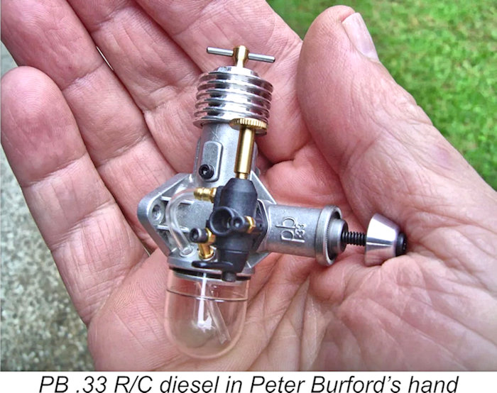
As we might expect with an engine of this displacement, the PB .33 is a very small engine. The accompanying view of the engine in Peter’s hand gives some idea, while the image of the engine beside a AAA battery which appears beow at the left provides a more definitive yardstick.
All steel parts were fully hardened and ground to extremely precise dimensions. In a departure from the more familiar material specification, the piston was hardened steel instead of the usual cast-iron. This "hard-on-hard" design means that the "pinch" of liner on piston at TDC must be very light, so good compression is achieved by grinding This concept clearly works very well in the PB 0.33 cc diesel. The piston/liner fit in my example (engine no. 0098) feels silky smooth when turned over, and the engine starts and runs very well indeed, as we shall see. If set up at Top Dead Centre with the piston lightly oiled, the compression seems to hold indefinitely. The engine was CAD-designed, with all tolerances being worked out so that no "mix and match" assembly would be required - even when all tolerances stack up the wrong way in a given example, Peter was confident that the engine would still perform up to specification. Pretty much an example of the Cox approach to tolerances! Even so, all engines were test-run by Peter before packing and shipping.
The hollow point removes any raised area at the centre of the comp screw, also accommodating any slight pip on the contra-piston center. This eliminates any possibility of point contact while This shot at the right shows the cooling head and the simple tool that was used to tighten it up. Not easily visible is the 2-56 nylon grub-screw in the step above the last cooling fin that applies extra friction to the comp-screw as mentioned earlier. Somewhat surprisingly, all threads on the engine are Imperial as opposed to metric - a fact that was doubtless appreciated by US owners. Have another look at the above image of the comp screw, paying special attention to the tommy-bar ends. The tommy-bar is 1/16 in. dia. music wire, with the ends ground spherical on special tooling built by Peter. Not only does this look good, but it assists the press fitting of the tommy bar into the comp screw, also providing a nice “feel” for the operator.
The wrist pin was just about the only component of the engine that Peter didn’t make - rather, it was a hardened steel needle roller. Somewhat unusually, it was pressed into the conrod small end and rotated freely in the piston bosses – the opposite of the more commonly-encountered setup. Peter created a special tool to be used for the pressing-in operation. The tool ensured perfect centering of the pin in the piston, preventing any possibility of the wrist pin and cylinder liner ever coming into contact with each other. Light counterbores at the outer ends of the piston’s wrist pin holes served dual purposes. They aligned the piston in the tooling used to insert the pin, also acting as oil reservoirs to assist lubrication during operation. Now look closely at the end of the crankpin seen in the above image at the left. With the pressed-in wrist pin and tall crankcase geometry, jiggling the conrod onto the crankpin would be nearly impossible with a conventional crankpin. The little bevel on the inner edge of the pin allowed the rod to be rocked easily onto the pin with the shaft at the TDC position. The amount of bearing surface lost was miniscule, also being confined to the lightly-loaded crankpin pressure surface around BDC. It may also act as an oil reservoir for the conrod big end. Other assembly-challenged engines such as the AHC diesel benefit from such a modification.
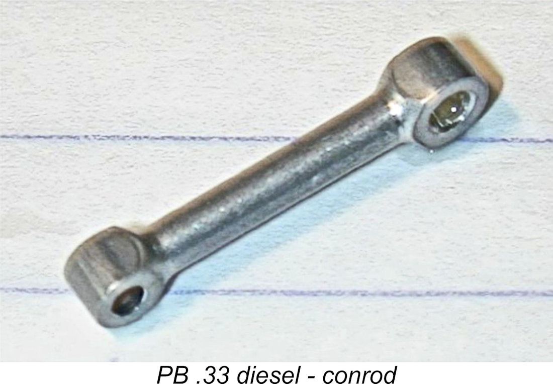
This means that the piston can only be assembled correctly facing one way. The inexperienced often neglect to note which way a piston faces when disassembling an engine, hence having a 50% chance of reassembling it with the piston facing in a direction that prevents it from running or at the very least essentially requires it to be run-in all over again - or more likely, run-out! In the same image, look at the finish on the edges of the crank-web, the ground pad at the crank-pin base that prevents the rod rubbing on the web, the oval induction port and the precisely-angled Schnuerle ports in the liner. It's as if each engine was being made to serve as an exhibit in a model engineering exhibition! The shaft was internally threaded at the front, with a 4-40 Allen-head screw being used to mount the prop. The prop driver was keyed by two little flats ground onto the shaft, just visible in the above photo. The steel prop driver was perfectly plunge-knurled and fully hardened. This hardening and a slight protrusion of the main bronze bush ensured that should anyone fit a Ron especially liked the tiny conrod pictured here. It was fully-machined from aluminium alloy and had the ends formed using the method that Ron had deduced while restoring a Taipan for one of his readers. This method, fully described on one of the Taipan Restoration pages, produces very clean profiles simply and safely. But that only takes care of about 280 to 300 degrees of the end. The remainder must be machined integral with the rod shank in such a way that it merges neatly with the profile job. The rods made by Peter were just about as perfect as you can get.
The intake position is a bit unusual – the far earlier Cométe, Cannon and Majesco Mite FRV engines had used a similar intake location, but it was far from common. While the engine can certainly be mounted with the cylinder poking up vertically like an Arden Atom, Peter envisioned it being mounted as a side-winder in a little control liner, with the head pointing towards the inside of the circle. This would place the venturi upright, with the tank pointing to the outside of the circle where centrifugal force would promote draining to the last drop while in flight. It would also enable a very neat twin-cheek cowling to be fitted in a scale installation. Notice that the tank is arranged so that the fill nipple would be above the filled fuel level in such an orientation, so there would be no leakage. A similar mounting orientation could of course be used in a free flight or R/C model if desired.
The view on the left shows the same engine viewed from the rear. Notice the serial number: four digits to accommodate the potential numbers envisaged. This one is 0000 - the production prototype (there were also pre-production prototypes). The injection-molded plastic backplate screwed into the recessed rear of the crankcase, registering on a narrow step in the case opening. The boost channel "bump" that also carries the liner locating screw is clearly visible in this photograph. The screw is fully supported by the full depth of the bump; just above that is the short internally-formed blind channel that connects the piston skirt port to the angled Schnuerle boost port.
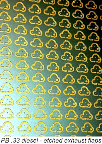
The lost wax (investment) casting process used to create the cases is a bit of a black art. Basically, a die must be created to produce a wax replica of the case which can then be potted (invested) in a formable material able to take the stress of molten metal once it is set. When this material sets, the wax is melted out to make room for the metal which replaces it (this is a special wax that leaves no residue - some use a centrifugal table to help get the molten wax out). Since making the wax "positive" pattern is a relatively gentle process, the die can be aluminium, which is easier and cheaper to machine than the steel die that would be required if it were to take the molten metal directly. Regardless, the die must be made so that the wax pattern can be removed once cast. This means that any protuberances into the wax must be designed so they can slide out somehow. Peter did a superb job in The piece of abstract art in the image at the right is a plate of stainless steel, photo-etched to form the little exhaust flapper which could be fitted at the owner’s discretion. Diesels don't really throttle all that well, partly due to the interaction between engine speed, combustion heat and compression setting. Peter thought that the engine would make a good "school-yard R/C" engine if it could be controlled a bit. He reported partial success: closing the flapper dropped the RPM by about 20%. It also dropped the noise to near nothing (you can't get nothing because the prop itself makes quite a racket, as electric users know). Ron thought initially that these flappers were punched, but Peter commented that there'd be no way to do this in stainless steel without leaving a burr, so he prevailed on his contacts to have the flappers etched out. He made enough of these plates to finish a run of 3,000 engines, if he chose to go that far.
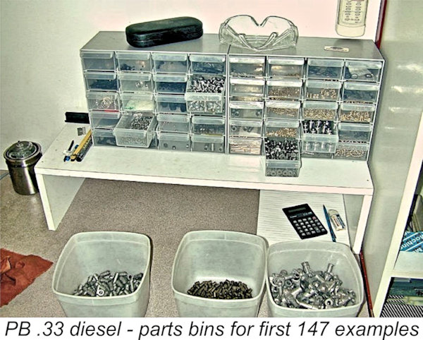
Ron was astounded to see at first hand the quantity and quality of tooling, jigs and fixtures that Peter had created to manufacture this engine. For those not clear on the distinction between a “jig” and a “fixture”, Franklin D. Jones’ publication entitled “Jig and Fixture Design” (The Industrial Press, 1942) defines a jig as a special tool that combines the work-holding function with means for guiding the respective tools to be used, while a fixture only holds the work while cutting tools The photo here shows the parts bins for the first production run of approximately 147 engines. The potential existed for the final production number to be far higher, as sufficient material and specialized tooling had been stockpiled to permit some 3,000 engines to be built in total if demand warranted this.
Ron made the general comment that Peter was a meticulous worker who was clinically neat in his approach to his work. Vincent Chai, who accompanied Ron during his visit with Peter, was a medical General Practitioner who observed whimsically that he wished that the average hospital was kept as clean as Peter kept his workshop!
The price was admittedly high: A$500, plus shipping. This was just under US$400 at the time. There were no agents, no bulk deals, and no discounts – if you wanted an engine, you bought it direct from the maker at the asking price. Peter knew that many would call this "overpriced", but he considered what it had taken to build them, pricing them to make each engine provide him with a modest return on his time and investment. If the market voted a resounding "no way" to the price, he was quite prepared to make no more of them. If this “take it or leave it” attitude seems extreme, there was a precedent: Peter confirmed the persistent story about an entire production run of unsold Taipans being used as fill under the concrete floor of the Adelaide Taipan factory. He should know, since he helped pour the concrete over them!
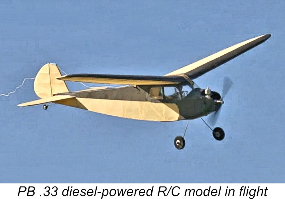
The challenge faced by Peter in justifiably setting such a high price was that far too many people looked at this engine purely as just another 0.33 cc diesel to be considered for use in model flying applications. Viewed in that light, there were far more modestly-priced engines of comparable displacement readily available to power those same models. Since the price of the engine was right up there at the "rare collectible" level as opposed to being in the What far too few people appreciated was the reality that the PB .33 was in the “rare collectible” category right off Peter’s workbench! It was sadly clear to me (and to some others like Ron) that despite the engine’s outstanding quality and original design (which had a high value in themselves), the engine was unlikely to become a best-seller at that price and that relatively few examples would end up being made as a result. Viewed as the rare and desirable collectible which it quickly became, its price was fully justified from the standpoint of a discriminating collector who liked small diesels. I’ve never regretted acquiring my own example while it was there to be acquired, and I feel good about the fact that the builder of the engine was the beneficiary of my custom! Peter’s final comment was that he built these engines to be flown, not merely to sit in a box or a glass case, as many of them doubtless did. Moreover, he practised what he preached, fitting examples to a number of models as seen in the accompanying photo. How well would a typical example have performed this function? Let’s find out! The PB 0.33 cc Diesel on Test My example of the lovely little diesel just described bears the serial number 0098. Like all the rest, it was supplied with all accessories, including examples of the high-quality molded 6x4 and 6x3 airscrews made by Peter. I didn’t have any performance data for those props, so I would have to use standard airscrews for which power absorption coefficients were known. However, I definitely planned to test both of the standard PB props along with all the rest. The manufacturer claimed speeds of 9,500 RPM with the 6x4 and 11,000 RPM with the 6x3, giving me an idea of the anticipated operating speed range. First step was to arrange for the mounting of the engine in a test stand. This was easily accomplished by drilling and tapping two suitably-spaced holes in a small piece of extruded L-section aluminium alloy.
The instruction sheet recommends a fuel consisting of a 35/35/30 mix of kerosene, ether and castor oil. A little cetane booster can be added if desired. Since that formula is pretty much my own regular test fuel formula, I was able to simply use what was in my usual test fuel container. Set up in the test stand, the little PB 0.33 felt absolutely superb. I followed Peter’s instructions to the letter, choking only sufficiently to fill the fuel line and then administering a “dry” exhaust prime (exhaust port closed). Above all else, flooding is the thing most devoutly to be avoided with very small-displacement diesels.
Once running, the engine proved to be quite responsive to the comp screw, but I found that the needle setting was a little ambiguous – the perfect setting was poorly defined. The right approach appeared to be to run the engine very slightly on the rich side rather than go looking for the absolute optimum setting. The considerable change in fuel head as the level in the tank went down underscored the desirability of using such a setting – the mixture became noticeably leaner as the fuel was consumed. I found it best to fine-tune the needle just prior to the tank running out. After a re-fill and re-start at this setting, the engine would run slightly rich initially on a full tank but would “come in” strongly towards the end of the run. When both controls were set in perfect harmony, the little PB .33 proved to be a very sweet runner, never missing a beat and generating very little vibration. I was particularly taken with the exhaust note, which was relatively subdued in terms of volume but retained a pleasing level of crisp "engine noise". I ran five tanks of fuel through the engine on the 7x5 and then proceeded to test a range of suitable props. The results are shown below.
I didn’t have power absorption coefficients for the two PB airscrews, but by slotting them onto the indicated power curve at the measured speeds, the coefficients applicable to these props could be determined quite readily. It’s worth noting that my example of the engine actually exceeded Peter’s performance claims for his own airscrews. The engine was claimed to turn the PB 6x4 prop at 9,500 RPM, but my example managed 9,900 RPM on that prop. It also beat the claimed 11,000 RPM on the PB 6x3 prop, topping out at a speed of 11,200 RPM on that one. It appears that I have a "good" example of the engine! The PB .33 delivered what I consider to be an excellent sports performance for a diesel of its displacement, developing around 0.038 BHP @ 10,300 RPM. Good power at moderate RPM - the peak power is more or less equivalent to that of a Cox Pee Wee glow-plug motor of identical displacement, but achieved at far lower RPM, allowing the use of a more efficient airscrew. It would do an excellent job of flying a small-field free flight model, also having enough power to keep a small control-liner airborne. Its excellent handling would have made it a pleasure to use in the field, while its sturdy high-quality construction would have ensured a long working life. I for one was thoroughly impressed! Conclusion
The engine is certainly a rarely-encountered and highly desirable collectible today. It was foreseeing this probable outcome as much as anything else that drove me to take Ron’s advice by investing in my own example. 22 years later, I remain very glad indeed that I did so! In 2024, the PB engine legacy was acquired by the 100% Aussie veteran-owned precision manufacturer and technical infrastructure provider, Secure Bits. Secure Bits respected the history of the Burford family, persuading Peter to remain available to serve as an advisor to Secure Bits. As of 2026, complete engines were no longer available, although some spares could be obtained from Secure Bits, who may be contacted by email at pbengine@securebits.com.au. ___________________________ Article © Adrian C. Duncan, Coquitlam, British Columbia, Canada First published October 2026 |
||
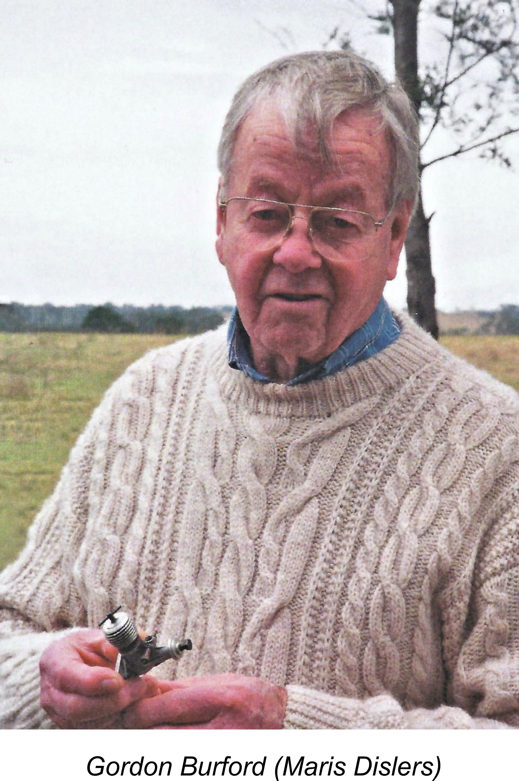 Most of my regular readers will have at least some familiarity with the name of Gordon Burford, Australia’s most famous model engine manufacturer. Over the years, Gordon was responsible for the design and production of the GB, Sabre and Taipan model engine ranges as well as a number of limited-edition replicas of such classics as the
  from an Australian manufacturing base. Accordingly, the business was wound up at that point, with Gordon supposedy retiring and Peter changing direction into injection molding and die-making.
 manufactured by himself alone in his extremely well-appointed workshop on the ground floor of his home nestled away in the foothills of the Tallebudgera hinterland some 90 km south of Brisbane.
 production version of his 0.33 cc diesel. It was at that point that he put in a phone call to the late Ron Chernich with an invitation to visit Peter at his home to inspect his workshop and examine the superb little 0.33 cc diesel which had been the fruit of Peter’s labours. Ron was only too happy to accept, recording the full details of his visit in an article which appeared in the
 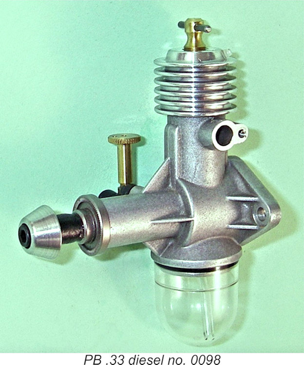 The engine that eventually emerged from Peter’s workshop in 2004 was the PB .33 diesel, a long-stroke Schnuerle-ported plain bearing front rotary valve induction compression ignition engine of 0.33 cc (.020 cuin.) displacement. Bore and stroke were 7.0 mm and 8.4 mm respectively for a displacement of 0.33 cc (.020 cuin.) exactly. The engine weighed in at a very modest 39 gm (1.37 ounces) complete with tank.
 Peter refuted Ron’s immediate impression that the quality of this engine was “uncompromisingly” high, stating that when it comes to model engines (including the PB .33 diesel), compromises are inevitable. Ron’s comments suggest that he was unconvinced by Peter’s argument! My independent review of this engine from both design and manufacturing standpoints fully supports Ron’s opinion – the engine was indeed built to an uncompromisingly high standard of quality.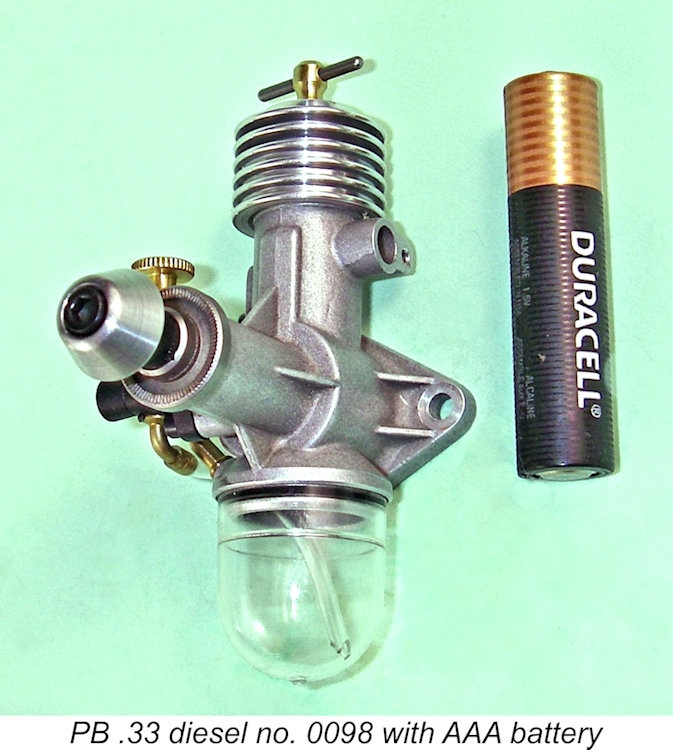
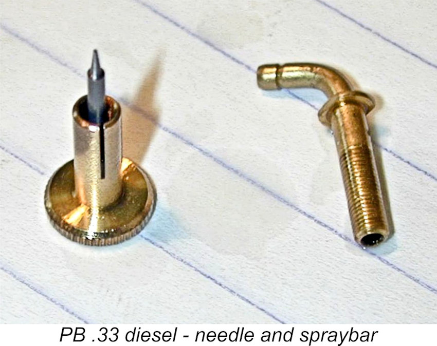 A further example of the basis for Ron’s “no compromise” viewpoint is to be found in an examination of the humble fuel needle. It was ground from 3/64 in. dia. music wire on the same center grinder that was used to grind the shafts and pistons. The needle was tapered for a length which was just long enough to meter through the jets, then quickly stepped out to full diameter to minimize the possibility of air leakage. The needle was pressed into the brass split thimble with such accuracy that there is no sign of binding as it is screwed into the spray bar. The very tip of the needle was neither sharp nor flat, but carefully rounded. The top of the brass thimble had a little circular depression added as an indexing mark. This was not cone-shaped, as it would be if touched with a drill bit, but spherical for no other reason than pure attention to detail. I think that I'll stick with Ron’s no-compromise theory!
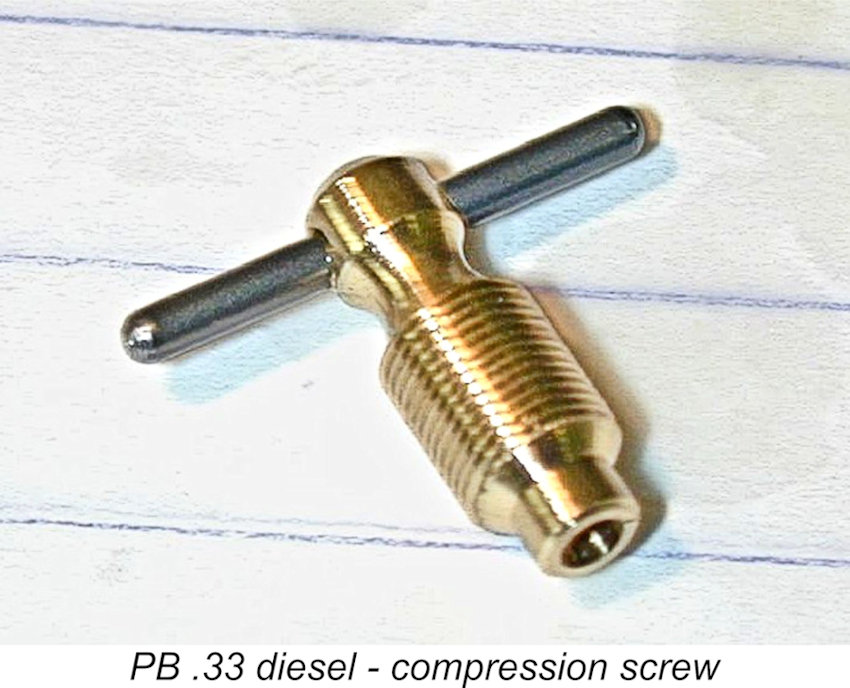 The compression screw was brass, with a fine thread and a comparatively large diameter to give a very pleasant "feel". Notice the hollow end-point. Years of experience with Taipan diesels led to this little touch. The center of the contra-piston will probably be slightly raised. So would the tip of a "flat" comp-screw end. These two not-quite flat surfaces will register against each other by way of point contact, providing very little friction when rotated against one another. The result is a comp-screw that will unscrew under vibration all too readily.
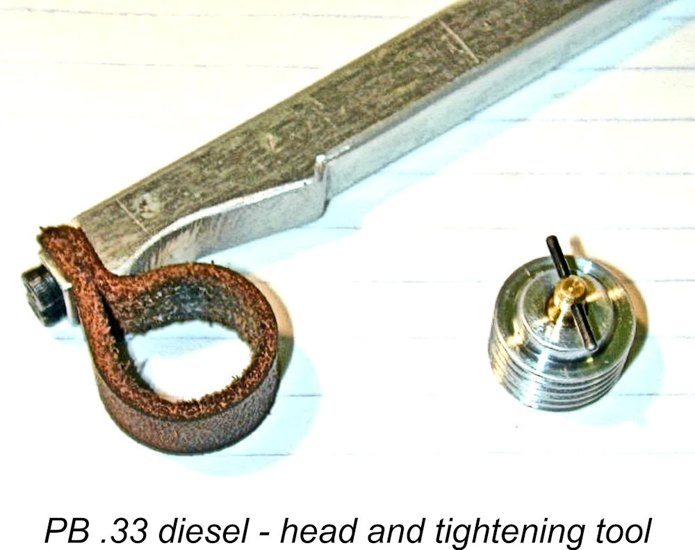 increasing the radius and area of the interface between the comp screw and contra-piston. The result is a greatly reduced tendency for the comp screw to unscrew while the engine is running. As a further precaution, a tiny nylon screw in the cooling head gives a bit more friction and a nice feel.
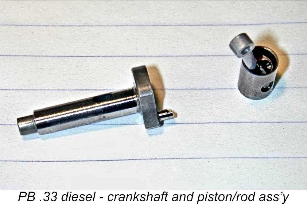 The image at the left shows the hardened mild steel piston and EN36A nickel steel crankshaft. Just visible if you know where to look is the piston skirt port which supplies the Schnuerle boost transfer port. This scheme has the theoretical advantage of assuring a flow of relatively cool mixture through the piston that helps keep the temperature down and assures lubrication of the wrist pin.
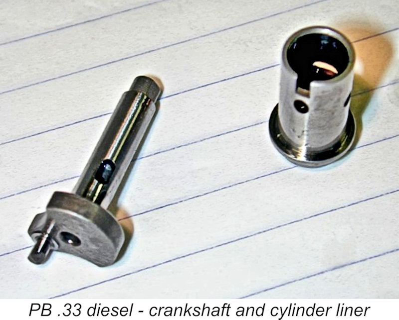 The view at the right shows the cylinder liner, which was a drop-in fit in the case. The slot in the liner registers with a 1-72 cap-head screw in the right-hand side of the crankcase to correctly align the ports and prevent the liner from rotating. Passages cast into the case at front and rear form the main bypass passages. The anti-rotation screw would block the boost passage, except that there isn't one in the conventional sense. Instead, a little channel cast into the bulge above the screw feeds the boost port with mixture fed from the previously-mentioned skirt port in the piston.
  pusher prop or use (AAAARRRRGGGHH!) an electric starter, the hardened driver bears against the bronze bushing and no harm would result (at least to the shaft!).
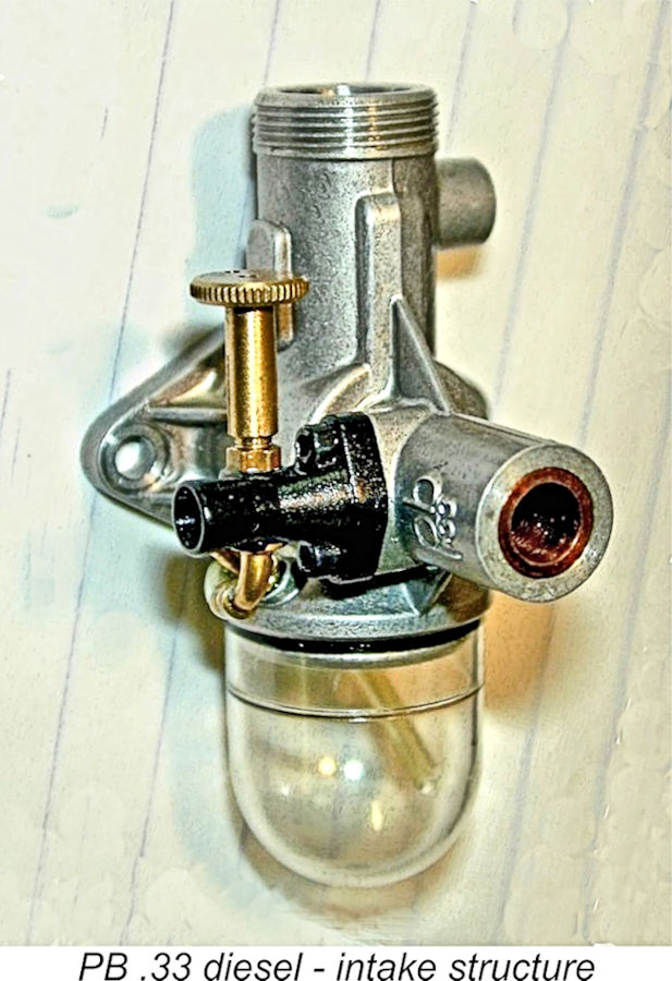 The intake structure was a plastic injection molding that mounted to what we'd usually call the right-hand side of the main bearing housing with 1-72 cap-head screws. Knowing a thing or two about injection molding, Peter was very particular regarding the specific plastic that he wanted for the venturi and backplate. Unfortunately, it was only available from a single supplier in the USA and cost over 100 times what might have been used if this wasn't a no-compromise engine (oh wait, I forgot; this isn’t a no-compromise engine, sez Peter……. yeah, right!) but Peter did not weaken - he ordered the plastic that he wanted for the job regardless of the absurd cost.
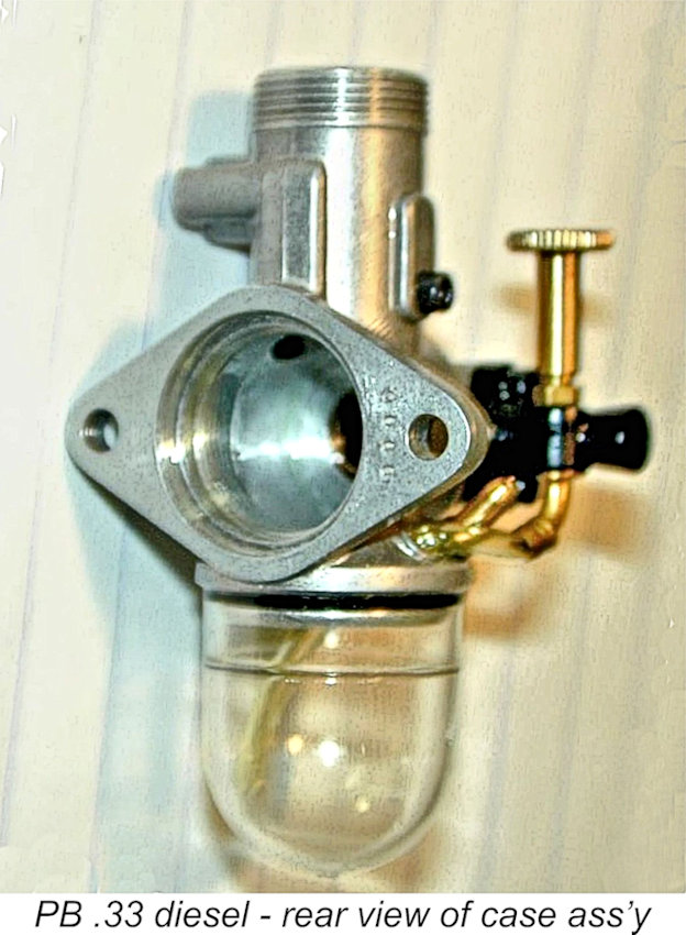 The tank itself was a crystal-clear plastic injection molding, snap-fitted and sealed with an O-ring. The little embossed ring on the tank allowed it to be cut down for shorter engine runs in free flight models (each engine was supplied with two tanks, so this was not a drastic measure).
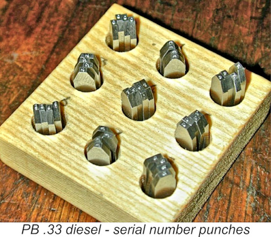 While on the subject of numbering, here are the number punches used to stamp the cases. They look spectacular, but began life as four sets of common-or-garden variety MSC 1/32 in. number punches. First, Peter ground the sides very precisely in relation to the location of the number so four can be stacked to give the correct number spacing and the four-digit number stamped with a single strike (explaining why there are four sets of numbers). Next, Peter painstakingly measured the baseline height of each numeral and ground the top and bottom of the punch so that all were exactly the same height, with all numbers sharing a common precise baseline. He commented that as expected, no two were alike - all had to be individually measured and ground.
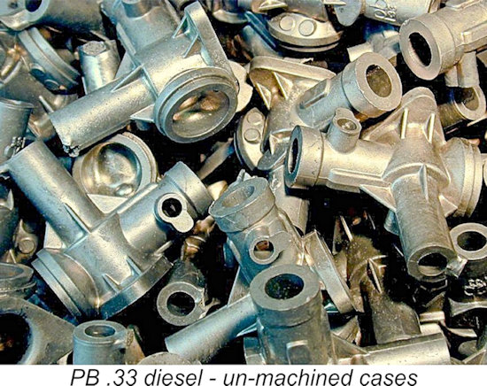 The photo at the left shows a bucket of cases, heat-treated and ready for machining. The heat-treatment process was principally intended to improve the machinability of the alloy, the case material being intrinsically strong enough as cast. The main bearing was a bronze bushing that was pressed in as a light interference fit. The generously-dimensioned bushing was flush with the front inside face of the case cavity - a thrust face on the front of the crankshaft web of the same diameter as the bushing ensured that no contact with the aluminium case could take place. Peter was unable to obtain the desired grade of bearing bronze locally, so it was imported from England.
 designing the die and inserts required to produce the cases for the PB .33.
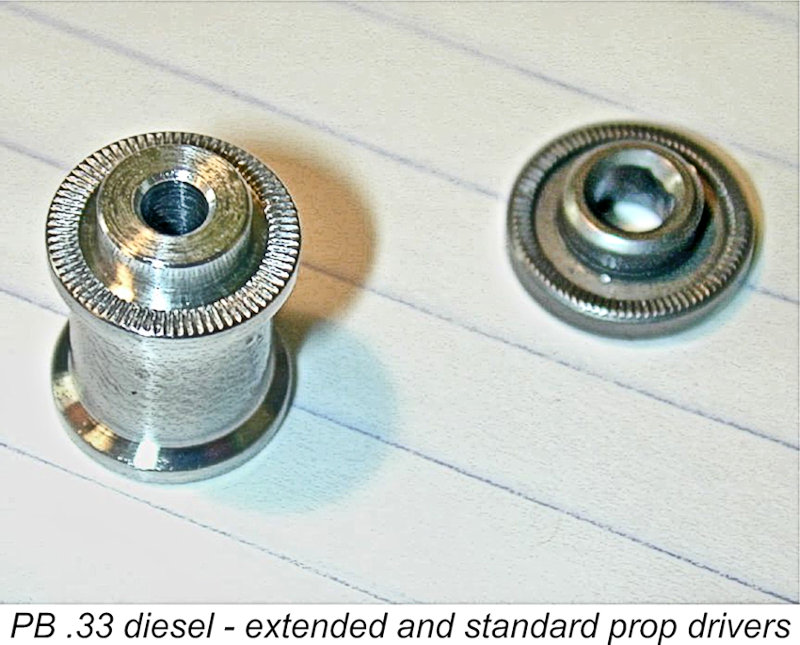 Apart from the exhaust flapper, several other accessories were made available for the PB 0.33 engine. The “cotton reel” (if you remember such things) in the shot at the left is the extended aluminium prop driver available as an accessory for the engine. The use of this accessory (with a far longer prop screw) would be of great benefit in facilitating the engine’s mounting in, say, a scale model with an extended or streamlined nose. Another accessory which was made available was a molded R/C throttle which reportedly worked quite well.
 perform the operation on the piece without any special arrangements for guiding these tools. The fixture must therefore be securely held ("fixed") to the machine on which the operation is being performed - hence the name.
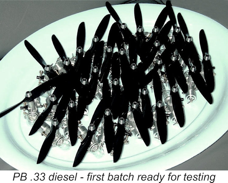 At the time of Ron’s visit in May 2004, the first examples of the PB .33 were ready to ship. Here we see a platter of completed engines ready for test running.
 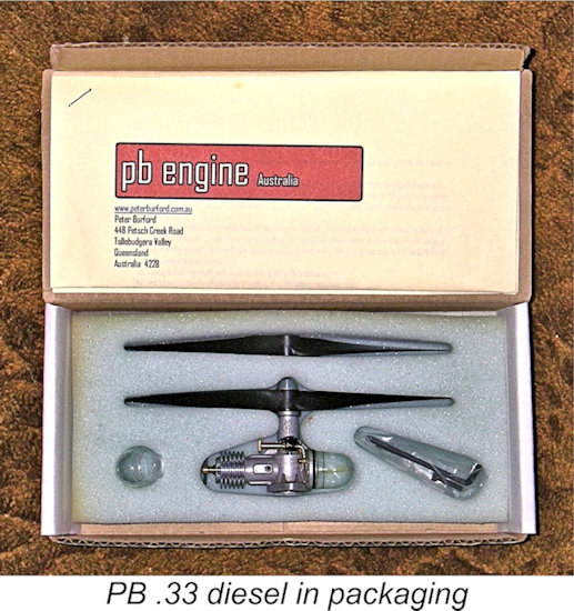 The presentation and packaging of the engines was absolutely top class. Each engine was supplied complete with two high-quality molded propellers made by Peter (a 6x3 and a 6x4), a spare fuel tank and O-rings, a set of Allen keys and an extra length of fuel tubing. All were packed in a generous foam insert. A set of very comprehensive operating instructions were printed on a double sided A4 sheet. A very classy package!
 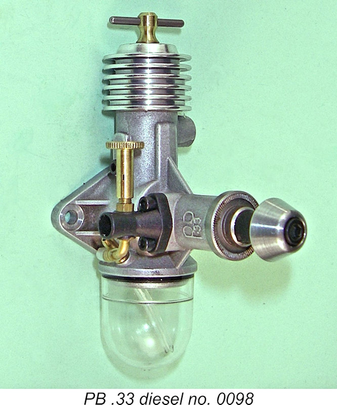 So was the PB .33 worth the money? Well, that's up to the individual to decide. The engine was not and still is not a beginners' engine - no very small diesel is, really. These were engines for the connoisseur who liked small diesels and saw value in such an engine which embodied the cutting-edge precision and quality with which every example of this little gem was richly endowed. I will say right out that over the years I’ve been privileged to handle a number of engines which are viewed as representing the pinnacle of the engine maker’s craft, and I have never seen an engine that exceeded the quality of Peter Burford’s superb little creation. In terms of the consummate craftmanship and attention to detail which went into each example, it was worth every nickel!
  "consumer" range, the engine's sales prospects to active modellers who were just looking for a powerplant to use were undoubtedly limited quite severely.
 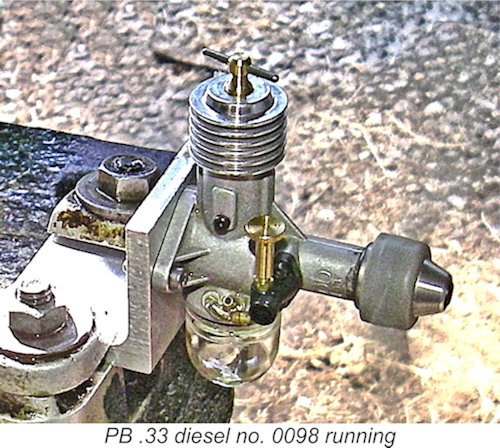 I decided to begin operations with a 7x5 APC airscrew fitted, purely for running-in purposes. The engine is so well fitted that it felt as if it didn’t need any running-in – indeed, Peter’s well-written and comprehensive instruction sheet made no comment regarding any running-in requirements. However, old habits die hard! Besides, that prop would give me a dependable starting point for my power curve.
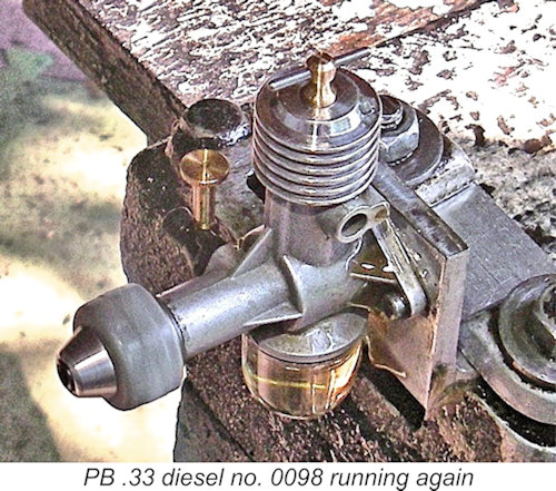 Peter’s advice proved to be completely sound - following his suggested procedure, starting was completely straightforward. The one thing that did become apparent was that the engine liked to have the needle opened a little from the running setting when making a cold start. Hot restarts were routine at running settings.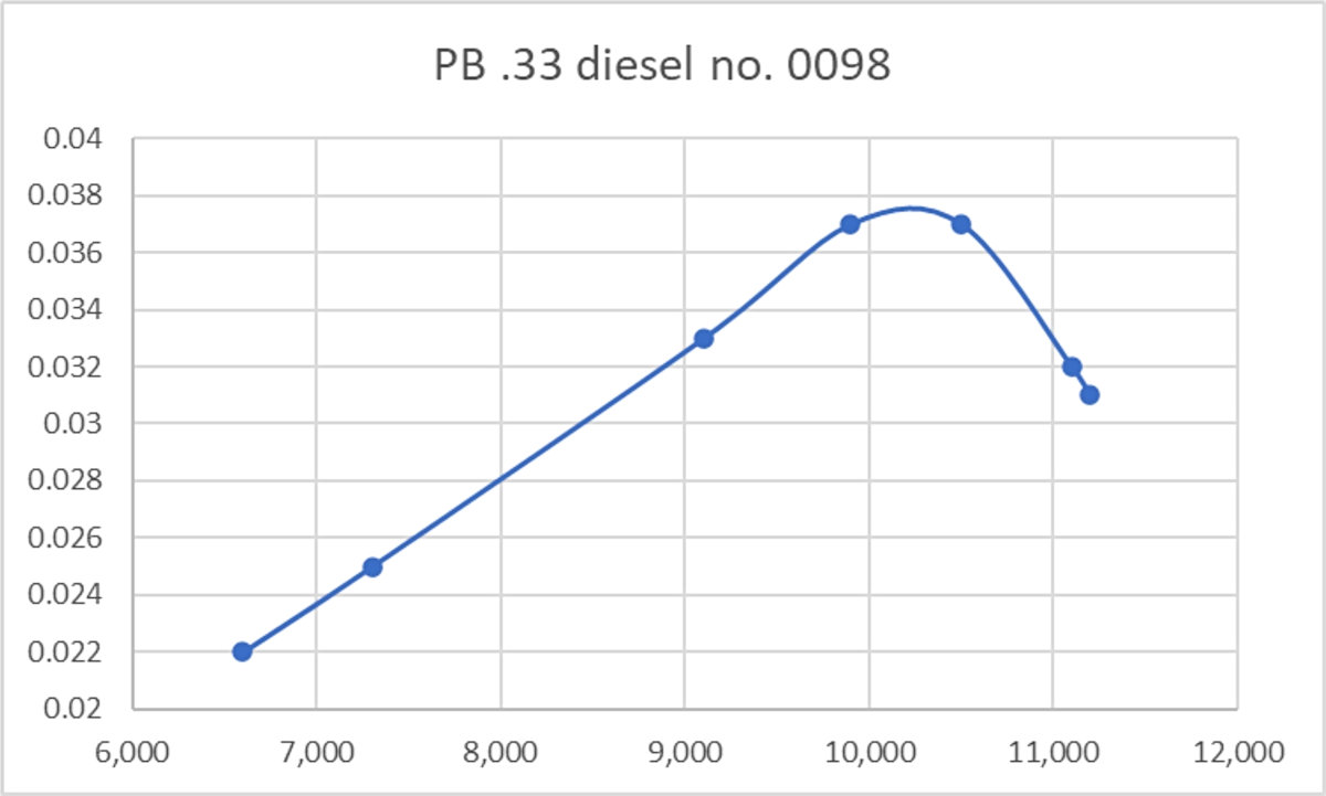
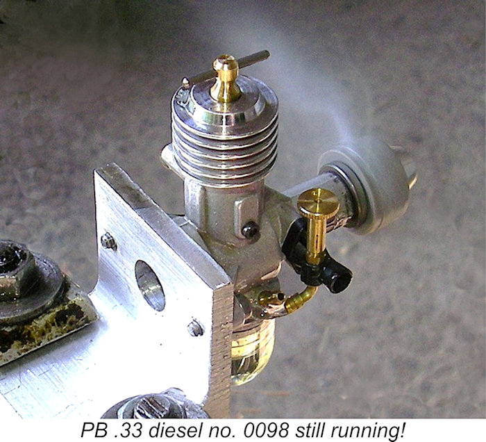 The PB 6x4 turned out to be a somewhat “slower” prop than its APC equivalent, while the PB 6x3 performed almost identically to the APC 6x3.
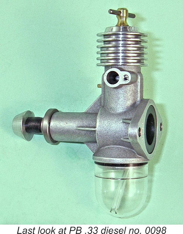 I’m unable to present an authoritative estimate of the number of these lovely little engines which ended up being produced. However, the word on the grapevine is that all too many dyed-in-the-wool diesel fanciers who might have been expected to become customers saw this engine as being too expensive to attract their attention, failing to recognize it as the rare collectible that it was obviously going to become in short order. Tahn Stowe believed that fewer than 200 examples were completed in total. It actually appears to me to be not unlikely that the original 147-piece batch seen by Ron Chernich was the only batch that ended up being made. If any reader has an example bearing a higher serial number than 0147, please get in touch!
| |