
|
|
The Cannon Engines
However, it was only a few years ago that I finally managed to track down a nice example of the post-WW2 Cannon 300 model. This particular engine appeared to be little used – it was certainly unmounted. It was accompanied by the lower half of its box – the lid had been lost, as had the instruction sheet. However, I was able to create a scan of that document. The 70 year old Cannon (older than me!) quietly aged another few years sitting on the shelf, since I didn’t then have the knowledge or equipment necessary to actually run spark ignition engines. During the interim, I acquired several more Cannon models which joined their silent partner on the shelf. However, things had all changed by early 2019, when I capped a year of research into spark ignition operation by successfully completing my own spark ignition support systems for bench testing. I’ve written up my experiences in a separate article to be found elsewhere on this website. The Cannon 300 was among the small handful of engines that I selected more or less at random to form the first group of sparkies to be run in order to test my new equipment. It started and ran in a completely Looking through my fairly extensive collection of literature on model engines of the 1940’s, I found that the Cannon engines were relatively under-reported by comparison with many other mainstream American marques. Indeed, my good friend and mentor Tim Dannels told me that very little material on the Cannon range has ever appeared in the pages of Tim's always informative "Engine Collector's Journal" (ECJ). I have no idea why this has been so, but regardless of the reason I could find little relevant commentary beyond the Cannon entries in Tim's invaluable "American Model Engine Encyclopedia" (AMEE); some technical tables featuring the Cannon engines; and a re-print of the Cannon instructions in Bernie Winston's often useful contemporary reference work "Model Gas Engine Handbook". In particular, there seemed to be next to nothing about the makers of the Cannon series. I hope that the present article will do something to enhance the visibility and historical interest of these highly individualistic powerplants. The Cannon Range – a Summary
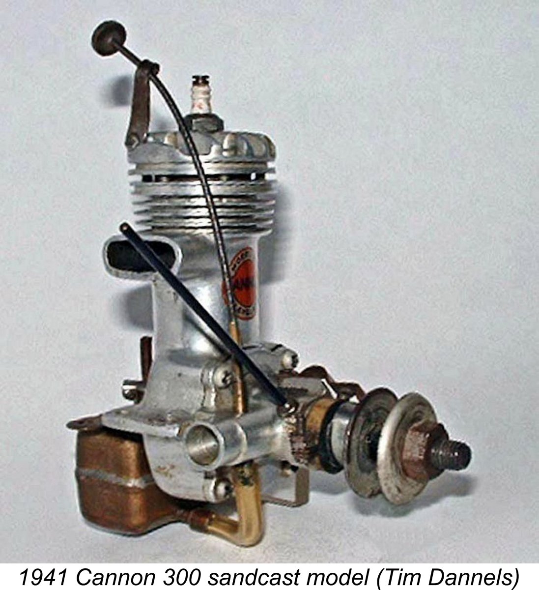
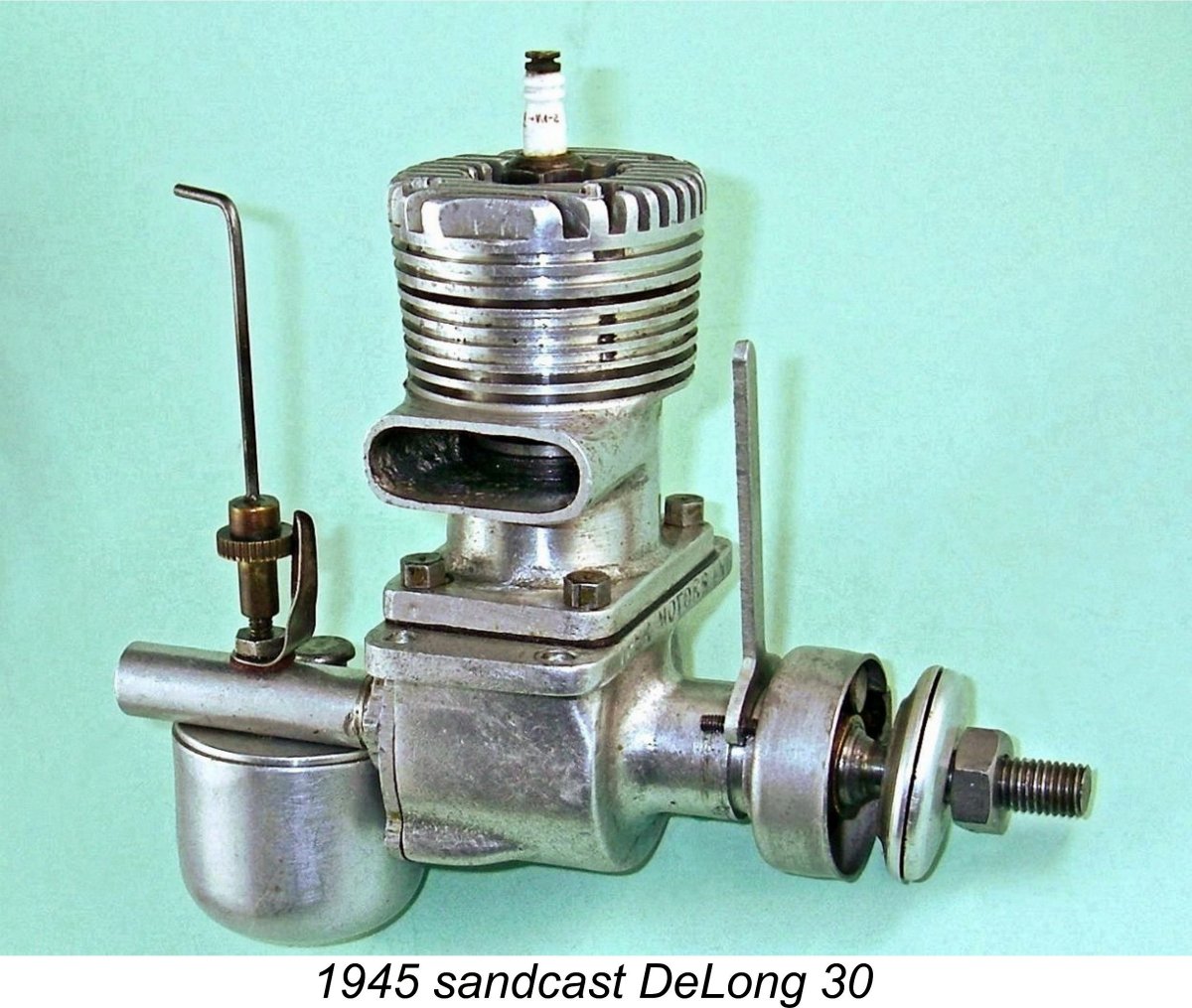
The Cannon company had its roots in a 1939 partnership between Everett DeLong and Bob Steele while both were resident in Lima, Ohio. Their DeLong and Steele (D&S) company of Lima manufactured a pair of .29 cuin. spark ignition models which appeared successively in 1939 and 1940 respectively. A 0.60 cuin. model was also produced by D&S in 1940, although very few of these were seemingly manufactured. There have been reports of a .331 cuin. model The original 1939 D&S 29 featured an updraft FRV intake with a conventional transverse needle orientation. It was the 1940 version of the same engine illustrated at the right that introduced the sidewinder intake with vertical needle having the long flexible extension that was to characterize the subsequent Cannon offerings. In 1941 Everett DeLong relocated back to Cleveland, Ohio, where he had lived prior to 1935. Premises for DeLong’s new Cannon Manufacturing Co. were established at 1561 East 17th Street in Cleveland, near what was then the campus of Fenn College. It was at this point that the Cannon range had its beginning by that name, although in reality it was essentially a continuation of the earlier D&S range, the design rights to which were evidently held by Everett DeLong.
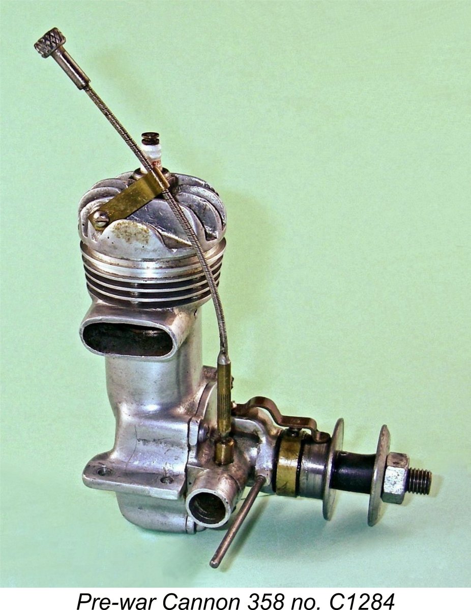
The pre-WW2 Cannon models both incorporated two of the main features which were to distinguish the Cannon range all along, having been introduced on the 1940 D&S 29 model. These were the “sidewinder” intake for the crankshaft front rotary valve and the very long flexible needle valve extension with its cylinder-mounted retaining clip which routed it up to a control knob located very conveniently above the cylinder head. At this stage, the sand-cast cylinder heads were conventionally attached with a circle of machine screws, which ensured that the fore-and-aft cooling fins were correctly aligned. Both models carried a distinctive orange, black and gold decal on the front of their upper crankcases. This is damaged or missing altogether from most surviving examples. However, even without the decal the 358 is easily recognised by its far "taller" cylinder head with deeper fins and a domed top which was required to accommodate the longer stroke. The timers used at this stage were typical pre-war flat-spring types which were axially oriented. Serial numbers for these engines appear to have started at 0001 and gone up from there. The two models were distinguished by the attachment of a C prefix to the serial numbers for the 358 units. The Pre-war Cannon 358 on Test
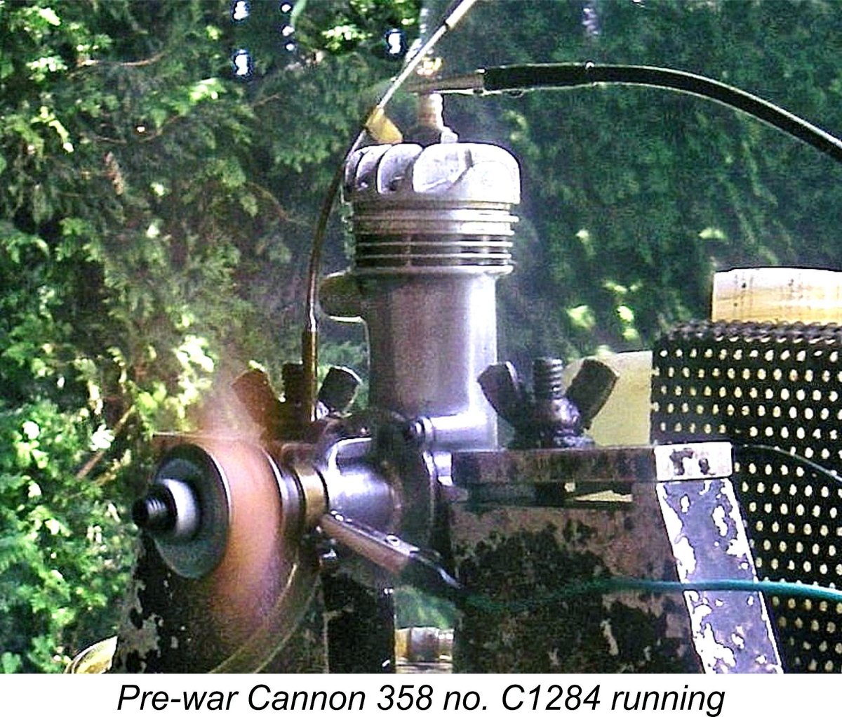
Installed on the test bench, the Cannon felt really good, with excellent compression. The play in the big end bearing was perceptible, but I judged that it would not prevent the engine from running just fine within the anticipated speed range. Subjected to the usual pre-operational function checks as described in my separate article on spark ignition engine operation, the spark plug proved to be in very good condition, while the timer was found to be functioning extremely well. I therefore hooked up one of my Larry Davidson spark ignition test support systems, fitted a Zinger 12x5 wood prop and got stuck in. I used my usual sparkie test fuel consisting of a 75/25 blend of Coleman camp fuel (white gas) and SAE 60 mineral oil (I use AeroShell 120). With a couple of preliminary choked turns and a small "dry" prime administered with the exhaust port closed, the engine began firing immediately. However, it would not keep running, blubbering to a quick halt. I had set the needle purely by guesswork at 2 turns, which proved to be considerably too rich. Around 11/4 turns proved to be the best setting.
Once set, the engine ran flawlessly, never missing a beat and displaying no tendency to sag. I gave it a few shakedown runs and then took a best speed reading on the 12x5 prop. The engine turned this prop at a smooth 'n steady 6,100 rpm, which I considered more than acceptable for a pre-WW2 engine of this displacement. I then began the process of seeking the engine's peak through the testing of a range of props. Starting and running qualities remained outstanding throughout, making this test a real pleasure. The following data were obtained.
As may be seen, the pre-war Cannon 358 turned out to peak at around 7,200 rpm, at which speed it was developing some 0.225 BHP. As far as I'm concerned, this is a very acceptable performance for an engine of this displacement and vintage. The excellent quality, handling and running characteristics of the Cannon would have combined with the available performance to make it appear quite attractive to American modellers of the late pre-WW2 era. I don't have an example of the pre-war Cannon 300 model to test, but I would expect a significantly lower output, albeit likely at more or less the same peaking speed. The Post-WW2 Cannon Models America’s December 1941 entry into WW2 put a stop to model engine manufacture as the necessary materials were diverted to military purposes along with the technical skills of the precision engineering firms and individuals who made such engines. It was not until September 1944 that the US War Production Board agreed to release sufficient material for non-military purposes to allow model engine production to resume.
A very successful series of disc rear rotary valve (RRV) DeLong 0.30 cuin. models was produced beginning in 1945 with a sand-cast version and continuing through two subsequent variants, the last of which appeared in 1949 as the sole purpose-built glow-plug unit to be produced by Everett DeLong. In 1946 an additional pair of spark ignition models having displacements of 0.45 cuin. and 0.60 cuin. made a brief appearance, although these seem to have barely made it past the prototype stage. If any were produced in series, their numbers were extremely small. The deservedly very popular DeLong 30 was the bread-and-butter model throughout. Finally, there were a very few prototype examples of a 0.295 cuin. (4.83 cc) diesel which never made it into production. I’ve written up the story of the DeLong 29 diesel in a separate article to be found elsewhere on this website.
The major change from the pre-war models was a switch from sand-cast to die-cast components. The cylinder heads were now of the screw-in variety in place of the former use of machine screws. This change was made possible by the fact that the heads now sported the unique circular cooling fins which distinguished the post-war Cannon engines. This meant that head alignment was no longer an issue as far as the external finning was concerned. Somewhat unusually, the differing displacements of the two models continued to be achieved entirely through the use of different strokes. The Cannon 358 can readily be distinguished from the 300 “across the room” by virtue of its domed-profile cylinder head, which was made necessary by the need to accommodate the 358’s longer stroke. The smaller Cannon 300 had a flat-profile head. The comparison view included earlier should make this quite clear. At close quarters, both models were clearly distinguished by having their respective displacements cast onto the front of their upper crankcases. The somewhat ephemeral decals which had been applied to the pre-war models were no longer used.
It’s not completely clear when Cannon production ceased. Both the Cannon 300 and 358 were included in the data tables which were published in the January 1948 issue of “Model Airplane News” as part of an article by Edward G. Ingram entitled “Model Motors for 1948”. They also appeared in the tables which formed Appendix II of Ron Warring’s book “Miniature Aero Motors” which was compiled in late 1948. However, they were not mentioned in the text of either publication. Consequently, their appearance in the tables does not necessarily confirm ongoing production. As far as I’m aware, Cannon never made a glow-plug model, evidently (and correctly) seeing Ray Arden’s late 1947 introduction of the commercial miniature glow-plug as a game-changing event which would consign the spark ignition motor to modelling history in very short order. It appears that the company quickly decided to abandon the model engine manufacturing field in favour of other perhaps more lucrative business lines rather than pursue the development of glow-plug units in competition with numerous other manufacturers. This makes it seem highly unlikely that production continued beyond late 1947 or just possibly early 1948. However, New Old Stock examples almost certainly remained available for some time thereafter. The Post-WW2 Cannon Engines Described
With one notable exception to be covered separately (see below), the Cannon engines were all basically conventional plain bearing crankshaft front rotary valve (FRV) two-stroke spark ignition engines featuring lapped hardened steel pistons running in liners made of some kind of iron alloy called "Cannalloy" by the manufacturers. That said, a number of examples of both the 300 and 358 models have turned up with ringed pistons. Both the 300 and the 358 shared the same bore of 0.750 in. (19.05 mm). Somewhat unusually, the additional displacement of the 358 was obtained entirely through an increase in the stroke from 0.678 in. (17.22 mm) in the 300 to 0.812 in. (20.62 mm) in the 358. The 358 was thus a long-stroke engine, in contrast to the short-stroke 300. These figures yield displacements of 0.288 cuin. (4.91 cc) and 0.359 cuin. (5.88 cc) respectively. The manufacturer’s claimed weights for the two models were identical at 6.5 ounces (184.3 gm). I can only report that my illustrated examples of the Cannon 300 and 358 weigh in at a slightly porkier 207 gm (7.30 ounces) and 211 gm (7.44 ounces) respectively with plug and timer but minus tank and ignition support system. Perhaps the factory figures were measured without a plug fitted ………however, since a Champion V2 plug of the type supplied with the engines weighs only 0.14 ounces (4 gm), this does not explain the discrepancy. Alternatively, the cited figure may have applied to the pre-war versions.
This brings up one of several design criticisms – the liner was completely unrestrained from turning within its bore in the upper cylinder casting. When tightening the screw-in head, it’s important to ensure that the cylinder ends up in the correct radial orientation relative to the bypass and exhaust passages in the crankcase. It would have been greatly preferable to incorporate some means of securely locating the liner in its correct radial orientation. This would have been very easy to arrange. The cylinder head itself had an externally-threaded spigot protruding from its underside which engaged with an internally-threaded recess at the top of the main casting, more or less like an oversized Cox glow-head. It was externally provided with two slots milled right across it at right angles through the circular fins to allow the insertion of a steel plate for tightening. The underside of the installation spigot was perfectly flat, notwithstanding the fact that the piston was equipped with a relatively shallow upstanding baffle on the transfer side. This was forced upon the designer by the fact that with a screw-in cylinder head there is no way to guarantee the alignment of the head once tightened. Accordingly, no slot can be provided in the head to accommodate the baffle.
Perhaps a more significant downside is the fact that the adopted arrangement results in the combustion chamber being divided into two more or less separate “compartments” at top dead centre, with the upstanding baffle separating them. The central location of the plug means that there will be some delay in the portion of fresh mixture trapped behind the baffle on the transfer side becoming involved in the combustion process. Finally, the need to utilize a cylinder head having a perfectly flat lower face means that there is no provision for the encouragement of displacement-induced swirl within the combustion chamber to encourage more rapid combustion. Overall, it must be said that this is a very inefficient combustion chamber. That having been stated, it was probably a non-issue in the case of the Cannon engines, which were only claimed to run at speeds in the 5,000 – 5,500 rpm range. At such speeds, delays in the full involvement of the charge in the combustion chamber would probably have little measurable effect. It’s only at significantly higher speeds that combustion efficiency becomes more of an issue. Moving on down, both the lapped steel piston and the “Cannalloy” iron bore in my examples are very finely finished and extremely well fitted. The cylinder liner was provided with rectangular transfer and exhaust ports which overlapped each other to a significant degree. Cylinder port timing was actually quite progressive by 1946 non-racing standards. The exhaust port opened at 110 degrees after top dead centre for a total exhaust period of 140 degrees, while the transfer port opened some 15 degrees later for a total transfer period of 110 degrees. These are actually quite reasonable figures for a general-purpose engine of the time in question.
The backplate was cast integrally with the main crankcase. The removable front housing was attached using four machine screws. Interestingly enough, an arrow showing the design direction of rotation was prominently cast in relief onto its upper front face. It incorporated the FRV intake venturi in unit as a single casting. Most unusually, the intake projected horizontally to the right-hand side of the engine. This set the spraybar in a vertical orientation. The induction port in the crankshaft was a perfectly circular opening. The induction timing provided by this arrangement was relatively conservative, as might be expected. The induction system opened at 65 degrees after bottom dead centre and closed at 20 degrees after top dead centre for a rather modest induction period of 135 degrees. There was no supplementary sub-piston induction. Looking closely at the intake arrangements, we encounter another design criticism, although this one is probably a reflection of the still-incomplete understanding of model engine design parameters as of 1945. The intake has a somewhat monumental internal diameter of no less than 0.300 in (7.6 mm), while the spraybar has a relatively skinny diameter of 0.125 in. (3.17 mm). Plugging these numbers into Maris Dislers’ invaluable Intake Choke Area Calculator reveals that the effective choke area is a generous 21.99 mm2. The calculator tells us further that the minimum operating speed for a 4.91 cc engine like the Cannon 300 drawing through this intake structure is 9,181 rpm. Even the 5.88 cc 358 has a theoretical lower operating speed of 7,667 rpm. Both figures are well above the anticipated operating speeds of these engines, leading us to expect that suction would be an issue at the somewhat lower anticipated operating speeds. The needle valve assembly itself is another of the unusual features of the Cannon 300 and 358. The needle is externally threaded to engage with an internal thread inside the needle end of the single-jet spraybar. It has a small-diameter knurled extension which engages with a neat double-edged channel formed at the The timer on both of my examples is a simple yet elegant open-frame unit which is built up around a compact die-cast frame. The moving point is carried on a flexible bronze arm which was created by appropriate bending of a stamped bronze sheet having the required shape. This arm doubles as the closing spring and incorporates the cam follower in a single stamping. It is securely attached to the timer frame with a machine screw and locking washer. It looks very Mickey-Mouse, but works surprisingly well. The annular alignment of the steel prop driver is assured through the use of a Woodruff key as part of its mounting on the shaft. The cam is integrally formed on a rearward extension of the driver. The driving face of this component is left plain, presumably to allow for some prop slippage in the event of a hard crash. When describing a spark ignition engine, an important additional parameter which needs to be quantified is the dwell period provided by the engine’s timer. This is the angle of crankshaft rotation during which the points are closed and hence in direct electrical contact with each other, thus supplying current to the coil's primary circuit. Since sufficient real time must be provided during each revolution to ensure full saturation of the primary coil winding before the points open to trigger the spark, the dwell requirement varies from engine to engine, the main factor being operating speed. A slow-speed unit like a Brown Junior, Atom .099, Bunch, Elf or even an early Ohlsson can operate successfully with a relatively short dwell period of 50 – 60 degrees or even less. High-speed racing engines require much more.
In the case of the two Cannons, the cam provides a generous dwell period of around 80 degrees, which should allow ample time for the primary current to fully saturate the coil at any reasonably anticipated operating speed. This very simple timer is about as light as one could get, but nonetheless appears completely functional. I’d expect it to be quite dependable in service. The more complex “Strato-Timers” supplied with the later examples would likely be even more effective.
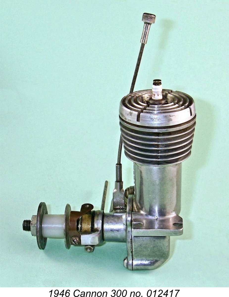
All of the engines seem to have carried serial numbers which were neatly stamped onto the outer surface of the backplate. My illustrated example of the post-war Cannon 300 bears the serial number 012417, while Tim Dannels sold similar engine number 012291. At present I have no firm information regarding the significance of these numbers - all that I can say is that numbers for the pre-war engines seem to have started at 001, or perhaps 100, and gone up from there. Pre-war engine number 887 (stamped on top of the left mounting lug) recently appeared on eBay. It seems possible that the numbering sequence continued without a break when post-war production resumed, in which case we would have evidence for the production of at leat 12,417 examples. However, it would take far more serial numbers to come to any defensible interpretation. The numbers applied to the 358 are unclear at present. It seems that the pre-war practice of including a C prefix was continued with the post-war engines, since my illustrated example bears the number C009903. At the time of writing, that's all I can say. The Cannon Four-Stroke Prototype
It’s presently unclear whether the Cannon four-stroke was a pre-WW2 or post-war production, but the fact that all of its castings were sand-castings suggests that it was likely a pre-war effort insigated by Everett DeLong as an experiment. Both the aluminium alloy crankcase halves and the cast iron cylinder head were well-executed sand-cast components. The cylinder head in particular is an unusually complex component, incorporating both the rocker arm saddles and the valve seats. It has not been possible to obtain any dimensions for this unit, but those who have seen it estimate its displacement as around 0.60 cuin. The engine was well ahead of its time in some respects. For one thing, it incorporated a barrel-type throttle unit which functioned very much along the same lines as those fitted to far later R/C models. The fact that it featured a somewhat rudimentary muffler also put it well ahead of the pack. The level of effort that went into the creation of this engine strongly suggests that it was at least being considered for series production. The fact that the company name was prominently cast in relief onto the crankcase supports this notion. However, the illustrated example is presently the only known survivor, seemingly confirming that the design never actually achieved production status. No doubt it would have been an extremely costly engine to manufacture – the work involved in machining the cylinder head assembly alone would likely have been prohibitive. In the absence of any further examples or information, that’s about all that can be said about this very interesting product from the Cannon company. If anyone knows more, please get in touch! The Post-war Cannon 300 and 358 on Test
However, thanks to my successful completion of a very dependable transistor-controlled spark ignition support system for bench testing, I was in a position to conduct my own full test of both the Cannon 300 and 358 running on spark ignition as designed. I had already confirmed that the 300 ran well, since it was one of the three units which I had selected as my test examples to prove the effectiveness of my new spark ignition system. The prospect of conducting a full test of these engines brought me face to face with one of the real mysteries relating to the Cannon engines – the manufacturer’s recorded airscrew recommendation. The factory literature associated with both Cannon offerings cited a 14 in. dia. airscrew of unspecified pitch as being the correct prop for both models. Reference to the various published data tables in which the engines appear consistently clarifies the reccommended size as a 14x8 prop. The 300 was claimed by the makers to turn this at 5,000 rpm, while the claim for the 358 was a slightly higher 5,500 rpm. The instruction sheet was missing from the contents of the incomplete box which accompanies my example of the post-war Cannon 300. However, thanks to the inclusion of a reprint of those instructions in Bernie Winston's previously-cited book, its text was available for reference. The instruction sheet not only confirmed the recommendation that a 14 in. diameter prop should be used but went further, stating that airscrews of under 12 in. dia. should not be used.
This reinforced my growing suspicion that the manufacturer's recommendation was actually related to their pre-war model and had not been updated when production of the revised design began after the war. It's perhaps significant in this context that the engine illustrated on the instruction sheet is a pre-war model. Perhaps they had a whole pile of pre-printed instruction sheets which they wished to use up rather than go to the expense of doing an updated re-print. After all, the starting and running instructions remained completely valid. Recognizing this possibility, I decided to trust my own instincts by ignoring the cited prop recommendation. Instead, I began my testing with a Zinger 11x7 wood prop, which my admittedly limited experience had shown to be a good airscrew for initial attempts at running a typical mid 1940’s sparkie of this displacement. Based on my established power absorption coefficient for this prop, it would require around 0.215 BHP to turn it at 6,500 rpm, give or take. I wouldn’t have given much for the Cannon 300's chances of matching this level of performance, let alone exceeding it! Instead, I selected a range of wood props that were on hand ranging from a 12x5 down to a 10x6. For some reason, it feels more appropriate to run a sparkie on wood props............. I also took note of the seemingly excessive choke area of the Cannon’s carburettor. To get around that issue, I decided to conduct my initial test runs with a restrictor inserted into the intake. Once the engine’s characteristics with the restrictor in place were established, I could try the effect of removing it. A short piece of neoprene tubing of the correct diameter inserted into the intake served as an effective restrictor. The recommended fuel was a mix of 3 parts white gas to 1 part heavy mineral oil (SAE 70). I used what has become my standard spark ignition blend of 3 parts of Coleman camp fuel to 1 part of AeroShell 120 mineral oil (SAE 60). Castor oil doesn't mix with gasoline or camp fuel, so you're stuck with mineral oil. AeroShell 120 is a far superior lubricant to any SAE 70 oil that was available back in the day.
I quickly learned the hard way that this advice was very well founded. The Cannon definitely didn't like a lot of fuel in the cylinder or crankcase for starting - just a whiff was all that was required. Even a little too much fuel induced a noticeable reluctance to fire and pick up. You had to get it just right. This being the case, I would not characterize the post-war Cannon as a particularly easy starter - straightforward enough when you know how, but it does take some knowing. The very inefficient combustion chamber probably has something to do with this. I eventually discovered that a single choked flick on a full fuel line was all that was required for a quick start. Even then, the engine tended to start very rich and take a little time to clear its throat before coming up to running speed. The good thing about this behaviour was that the engine could be started on the running setting. All that was necessary was to retard the ignition timing a little from the best running setting. Hot re-starts were very easy at running settings with the fuel line filled but no additional choking. Once running, the Cannon behaved perfectly. Its response to both the needle and timer advance was well defined, making it quite easy to establish the best running settings. Once set, running was smooth and consistent at all times, with a notably clean exhaust. The seemingly rudimentary timer appeared to perform perfectly up to the highest speeds tested. There was some vibration, but it was by no means excessive. in recording the following prop/rpm figures, I remained mindful of the fact that this example appeared to be unused apart from its factory test run. I therefore put on a few shake-down runs with the needle slightly rich and the timing slightly retarded. Thereafter, I confined my fully leaned-out measurements to the shortest period possible - just long enough to get a good steady reading. At all other times, I kept the engine slightly rich and retarded in deference to its apparently little-run condition. The switch built into the ignition support system proved to be invaluable in allowing the engine to be stopped at will for prop changes without disturbing any settings. I also found the location of the needle valve control knob above the cylinder head to be extremely user-friendly. The data set out below in tabular and graphic form tell the story.
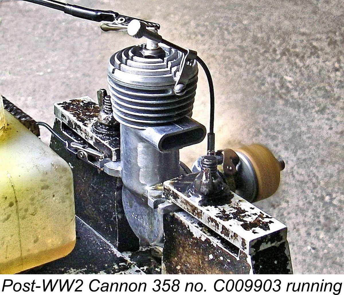
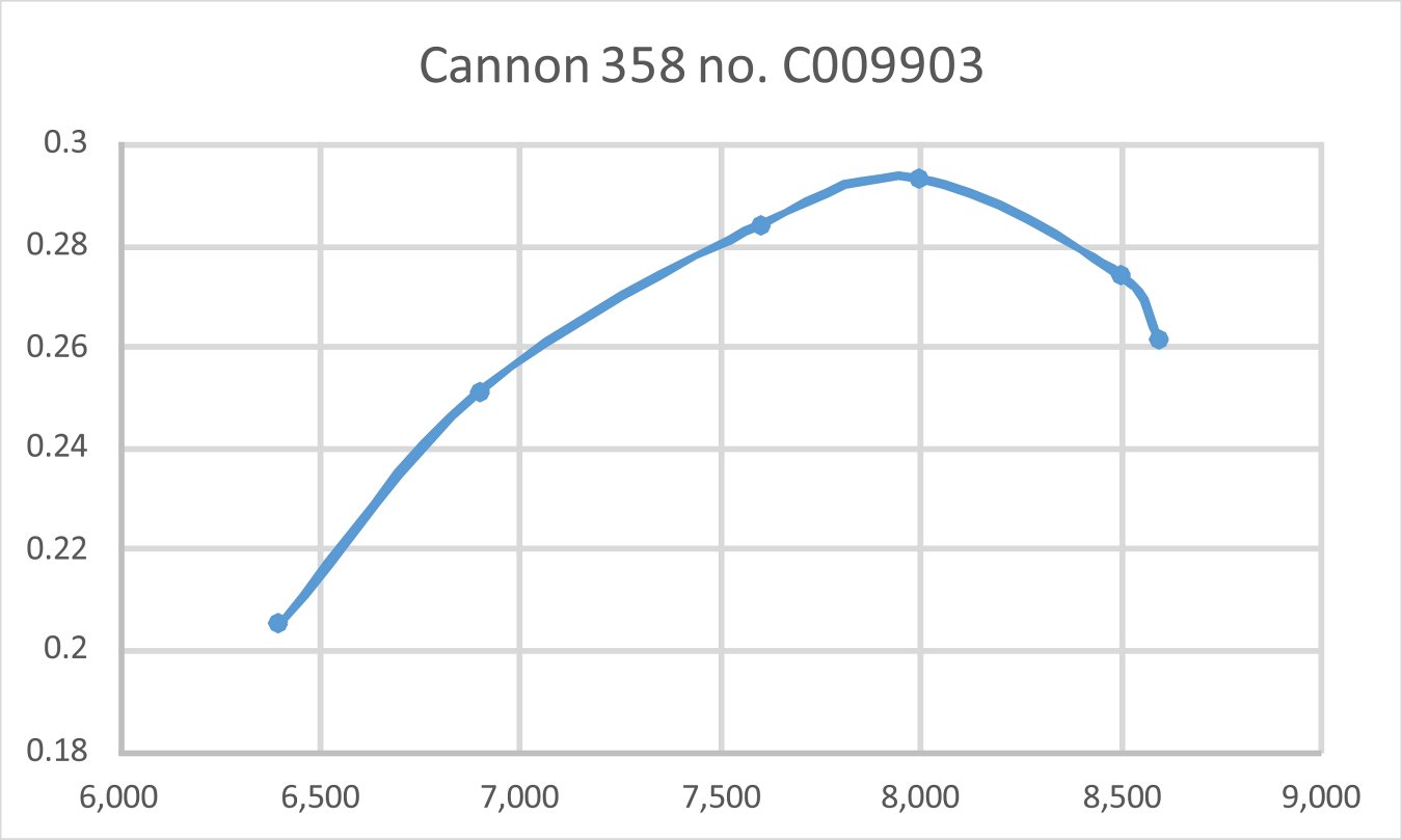
As can be seen, the engine appeared to peak out at 7,500 rpm, at which speed it was developing around 0.188 BHP. However, these figures were of course obtained with the neoprene venturi restrictor in place. To assess the effect that this constraint might have had upon performance, I removed the restrictor and then tried the 10x6 prop again. The improvement in performance was less than Moreover, there was a price to pay for this very modest performance increase - the needle setting became noticeably more ambiguous. A good setting could still be estabished, but it took some fiddling. Moreover, running seemed to be somewhat less consistent on a given setting - there was a bit of a tendency for the mixture to "hunt" unless the needle was exactly in the sweet spot. This seems to confirm the previously-noted expectation created by the application of Maris Dislers' Choke Area Calculator that running below 9,000 rpm might be problematic in terms of carburetion. I'd have to say that if I was planning to actually use this engine in a model, I'd probably leave the insert in place. On the basis of this test, I freely admit to remaining completely in the dark regarding the basis for the manufacturer's prop recommendation. I don't have a 14x8 prop to try, but for the life of me I can't see the tested engine turning such a prop at the claimed 5,000 rpm when it could only manage 5,400 rpm on a 12x5 airscrew. Moreover, the recommendation against the use of props of less than 12 in. diameter was a performance-killer - the engine would undoubtedly be at its best on something like an 11x6 or a 10x8, just like most of its similar-displacement contemporaries. All in all, a most Switching to Cannon 358 no. C009903 and changing to fresh batteries just in case, I elected to try the same props that had been used with the 300. The engine's handling characteristics were pretty much identical to those of its smaller relative. Accordingly, thanks to my prior experience with the 300 I had very little difficulty in achieving quick and dependable starts. Once running, the larger model ran just as well as its smaller sibling had done. It started and ran flawlessly throughout, showing no signs of mechanical distress at any time. The following data were recorded.
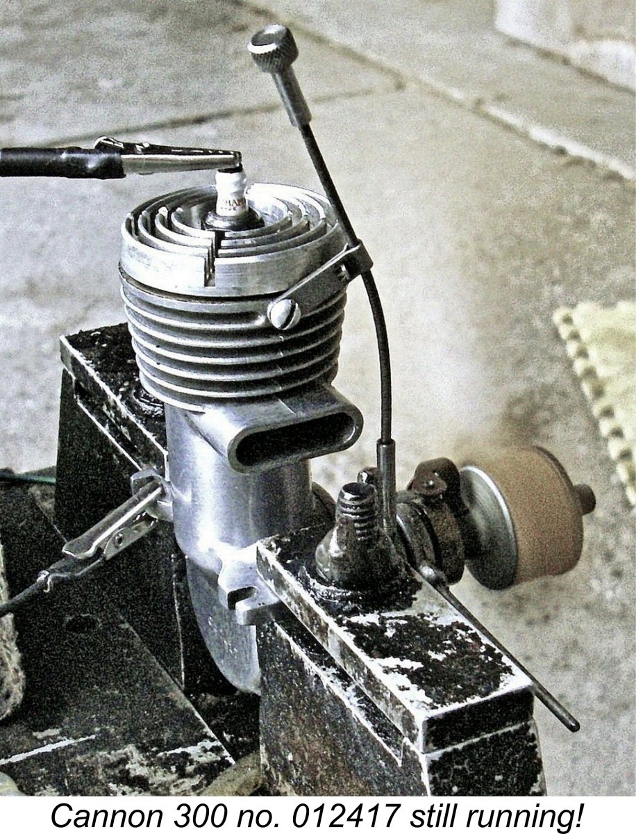
As can readily be seen, the post-war Cannon 358 showed itself to be considerably more powerful than its 1941 predecessor no. C 1284. We might expect this given the fact that the 1946 model was a complete re-design. Perhaps less expected was the extent to which the post-war 358 out-performed its 300 companion in the range. The 358 developed around 0.295 BHP @ 8,100 rpm - a very sturdy performance indeed. I was expecting considerably more torque due to the longer stroke, but was not expecting a 47% improvement in output for only a 20% increase in displacement. Still, there it is ......... As a final comment, none of the testing summarized above provides any support for the manufacturer's claim that the engine was expected to operate in the 5,000 - 5,500 rpm range. To get the best out of these units, you'd need to prop them for airborne speeds well into the 7,000 rpm range. Indeed, this observation applies just as much to the pre-war 358 model tested earlier. Conclusion On the basis of this review, the post-war Cannon 300 and 358 reveal themselves as competently designed and well-made representatives of the numerous American spark ignition engines which became available immediately following the conclusion of WW2. Their measured performance bears comparison with many contemporary non-racing engines of similar displacement. For example, the Cannon 300 certainly out-performed the considerably later ETA "5" diesel from England, which only managed 0.18 BHP @ 6,250 rpm in its test published in the September 1948 issue of "Aeromodeller" magazine. Much of the credit for the effectiveness of this engine must surely go to Everett DeLong, who seems to have brought the main design features over with him when he relocated to Cleveland prior to WW2 and started the Cannon company. His post-war successors seem to have continued the good work, resulting in the creation of a pair of well-made engines having a good performance by the standards of their day. It's a pity that they didn't continue their efforts into the glow-plug era - we might have seen some more fine products from them. As it is, we have a reasonable number of surviving examples of their excellent sparkies with which to entertain ourselves. These show up regularly on eBay and elsewhere, selling for quite reasonable prices. Anyone who likes model engines from the 1940's will appreciate owning one of these units, especially if he takes the time to provide himself with the means to actually run it! _________________________ Article © Adrian C. Duncan, Coquitlam, British Columbia, Canada First published June 2020 |
||
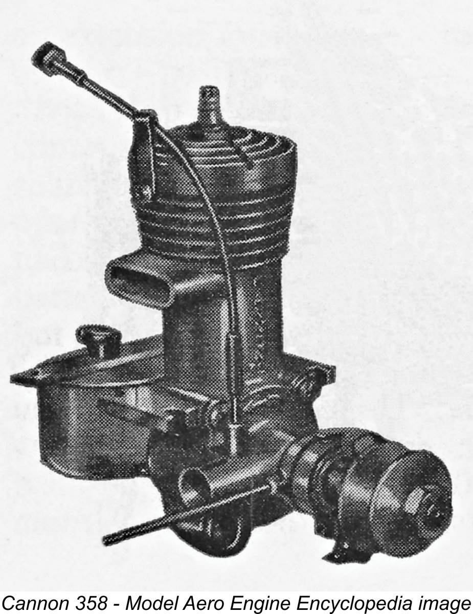 In this article, I’m going to treat myself to an in-depth review and test of a couple of my personal favourite spark ignition engines – the Cannon 300 and 358 models from Cleveland, Ohio. Ever since I first saw the image of one of the post WW2 Cannon 358 engines which appears on page 106 of “
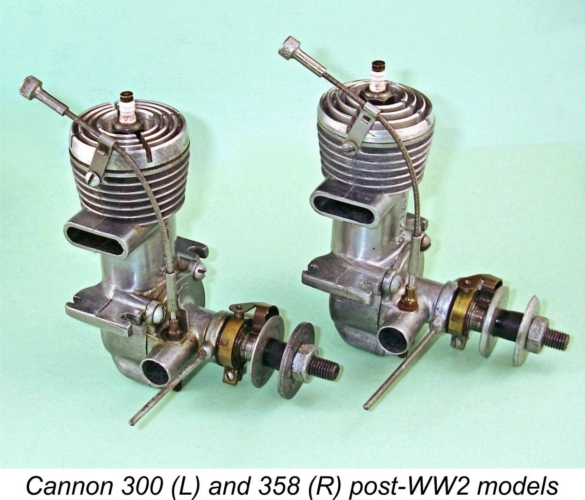
 The Cannon engines were produced by the Cannon Manufacturing Co. of Cleveland, Ohio, USA, initially at 1561 East 17
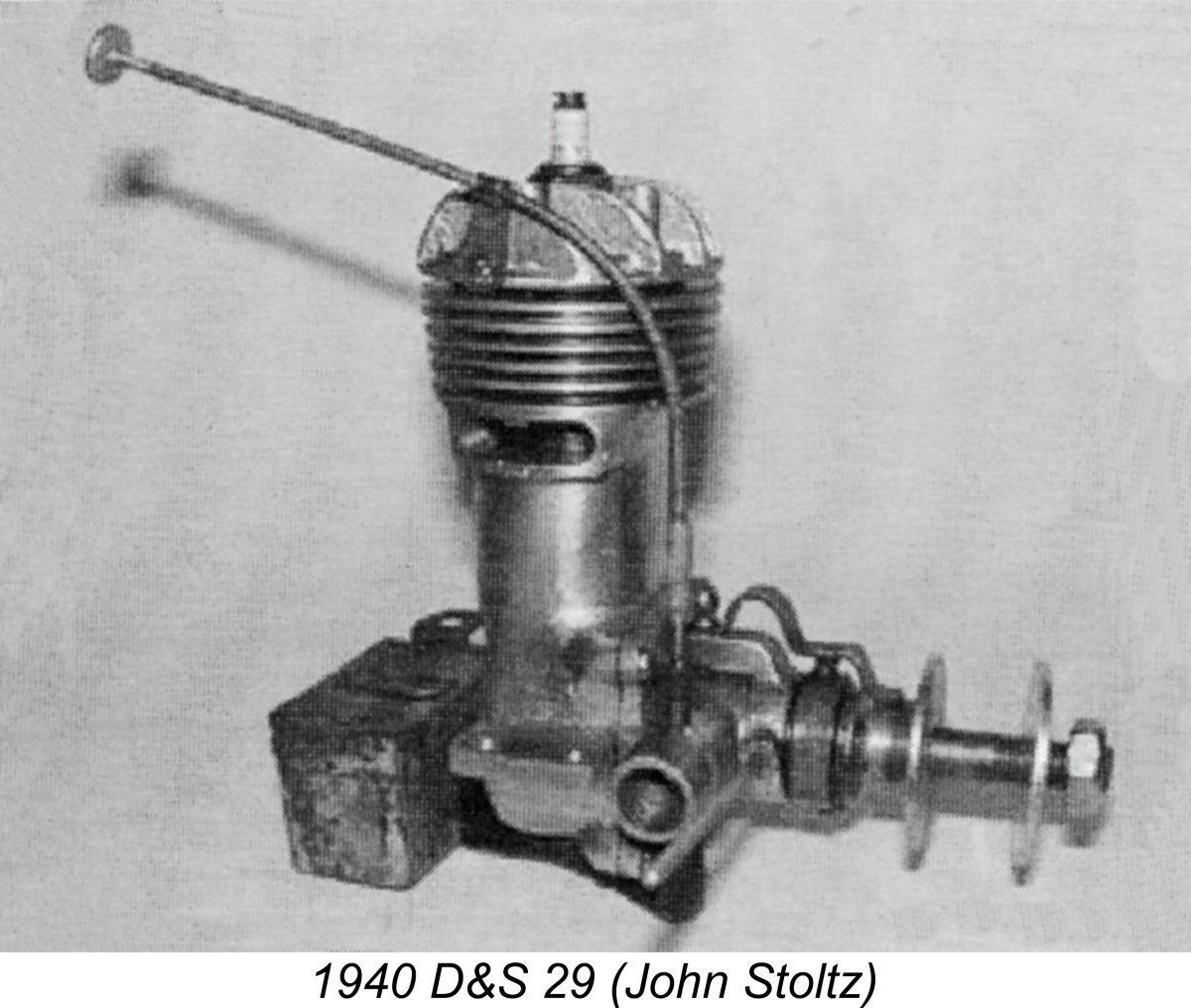
 Once I had the needle set properly, the engine started up right away. The needle setting turned out to be a bit on the critical side for best running - a very little movement either way had a significant effect upon running. However, a good setting was easily found regardless. I particularly appreciated the very convenient location of the needle control above the cylinder head. Response to the timer arm was well defined, making the optimum ignition timing very easy to establish.
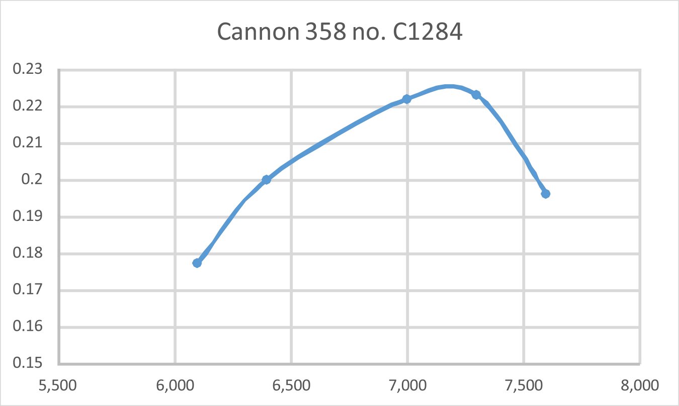
 Following the cessation of hostilities, Everett DeLong went out on his own with his Super Motors Inc. company which was located in Cleveland at 2093 East 19
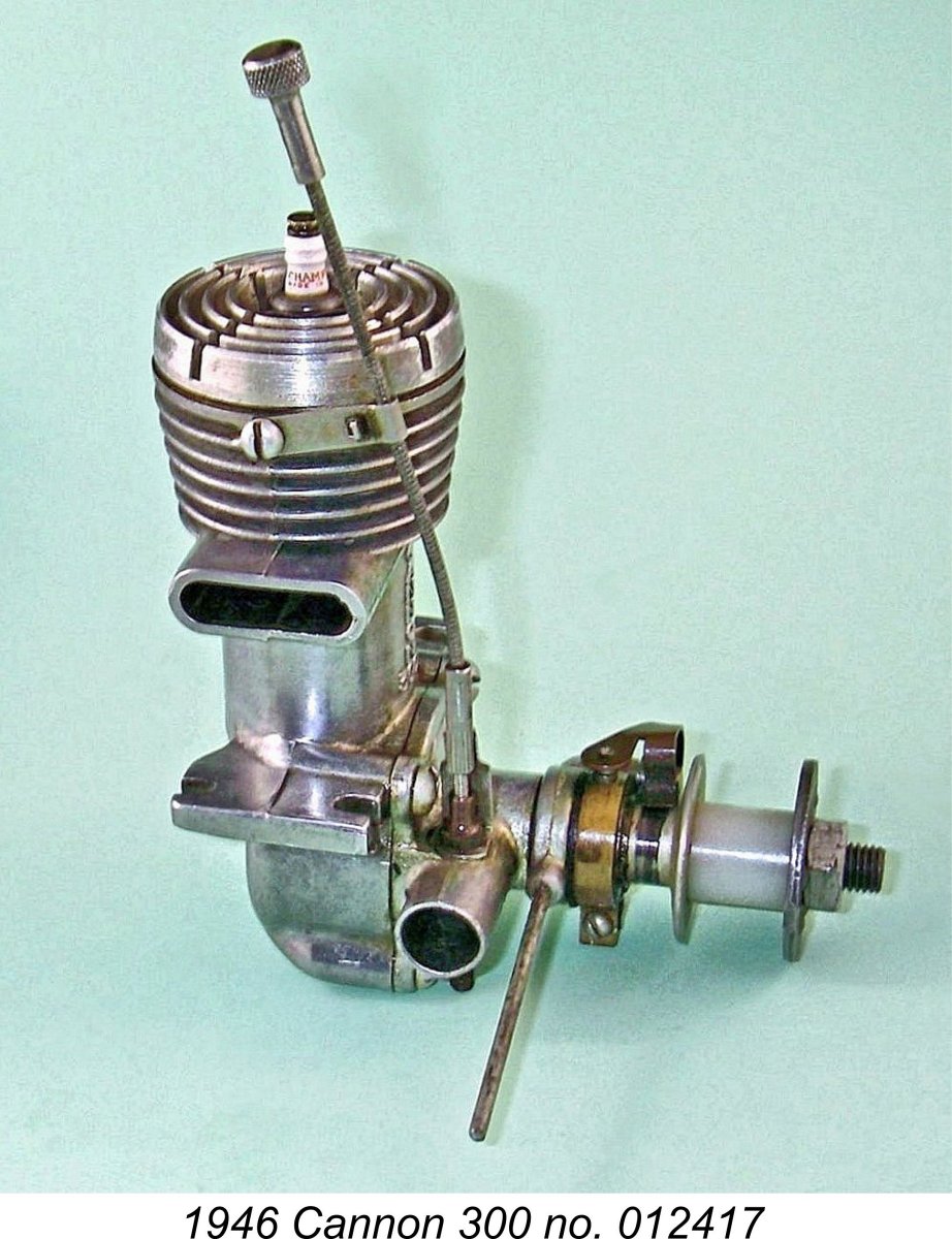 Meanwhile, the Cannon Manufacturing Co. was still very much in operation despite the departure of Everett DeLong. The company had relocated to presumably larger premises at 1878 East 18
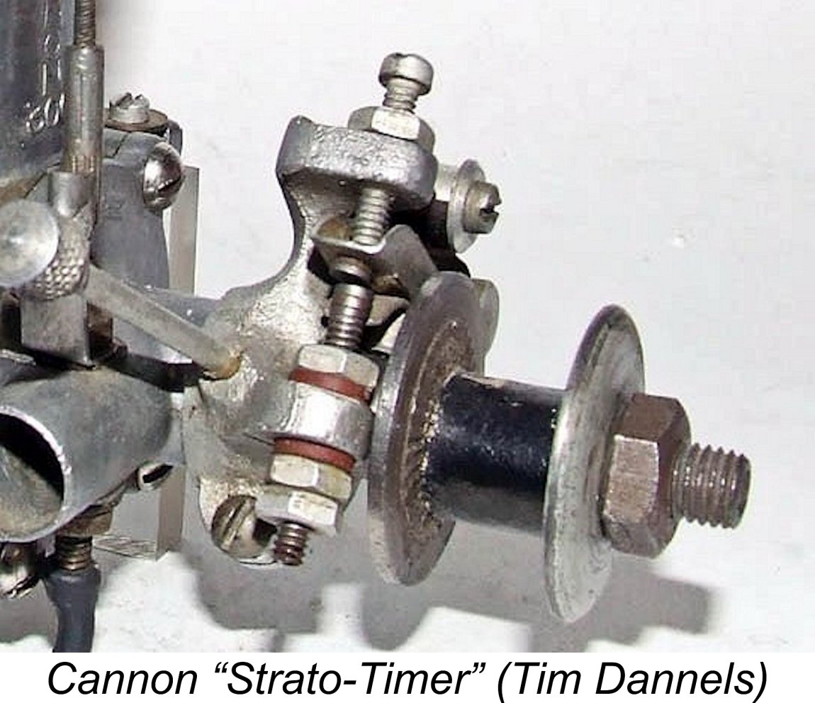
 Both the post-war Cannon 300 and 358 models were basically very similar, to the point that the following description generally applies to both models. I will do my best to point out the differences as and where they arise.
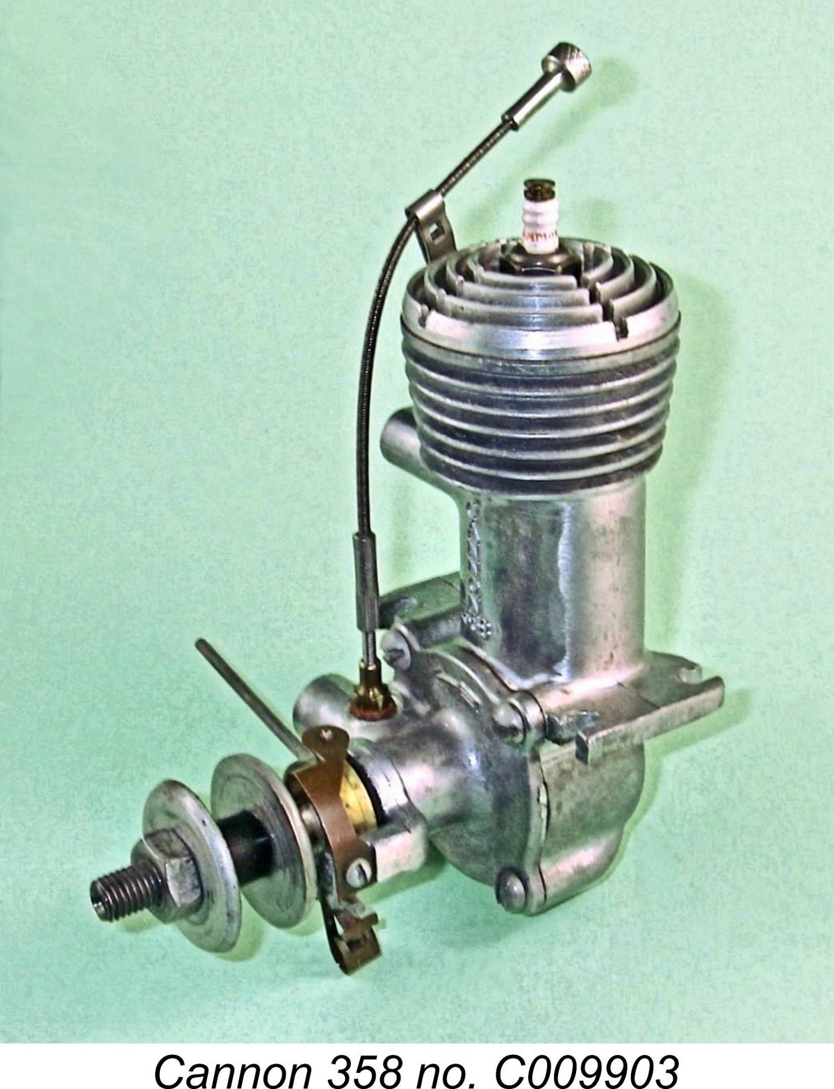 The engines were now based upon high quality pressure die-castings. The main casting incorporated the crankcase, mounting lugs, backplate, bypass passage, exhaust stack and cooling fins all cast as a single unit. The engine’s name and model number were cast in relief onto the front of the main casting. The cylinder liner was a simple drop-in component which was retained by a screw-in head. This threaded into a recess at the top of the main casting and bore directly upon the top of the liner, with a fibre gasket for sealing purposes. The head was the main "across the room" distinguishing feature between the two models - that used on the 358 had a distinctly domed profile as a result of the need to accommodate the longer stroke of that model.
 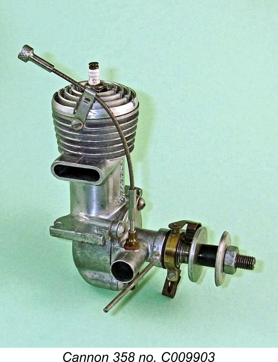 There are several downsides to this design. Firstly, the presence of the baffle limits the minimum possible clearance between the piston crown and the cylinder head at top dead centre. This in turn sets an upper limit on the compression ratio which can be incorporated. Even so, the measured geometric compression ratio of both models is a pretty healthy 8.0 to 1 - at the top of the normal range for general-purpose spark ignition engines of the period. This is consistent with the comment made by Edward G. Ingram in his article entitled “Recent Model Engines” which appeared in the June 1946 issue of MAN that “high compression has always been a characteristic of Cannon engines”. Indeed, Ingram claimed that the compression ratios of the 1946 Cannons like that now under review were actually greater than those of the pre-war versions. This is a completely believable claim.
 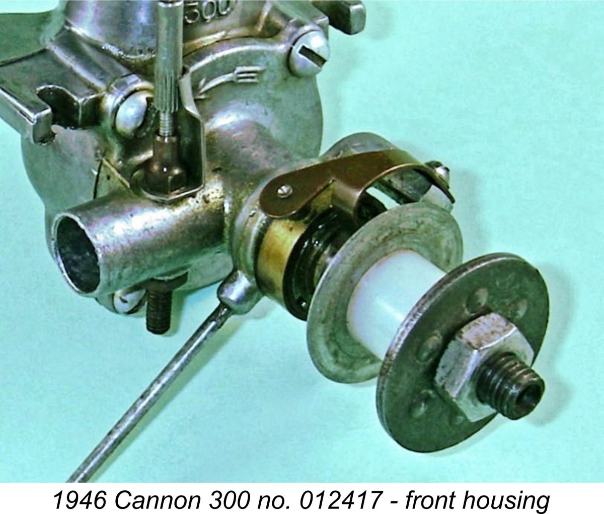 The piston drove the crankshaft through the use of a rod made of solid manganese-bronze. While this obviated the need to use bronze bushings at the small and big ends of the rod, it did make for a rather heavy rod. Again, at the low speeds at which these engines were apparently intended to operate, this would probably not be much of a problem. The steel crankshaft turned in a bronze-bushed main bearing
 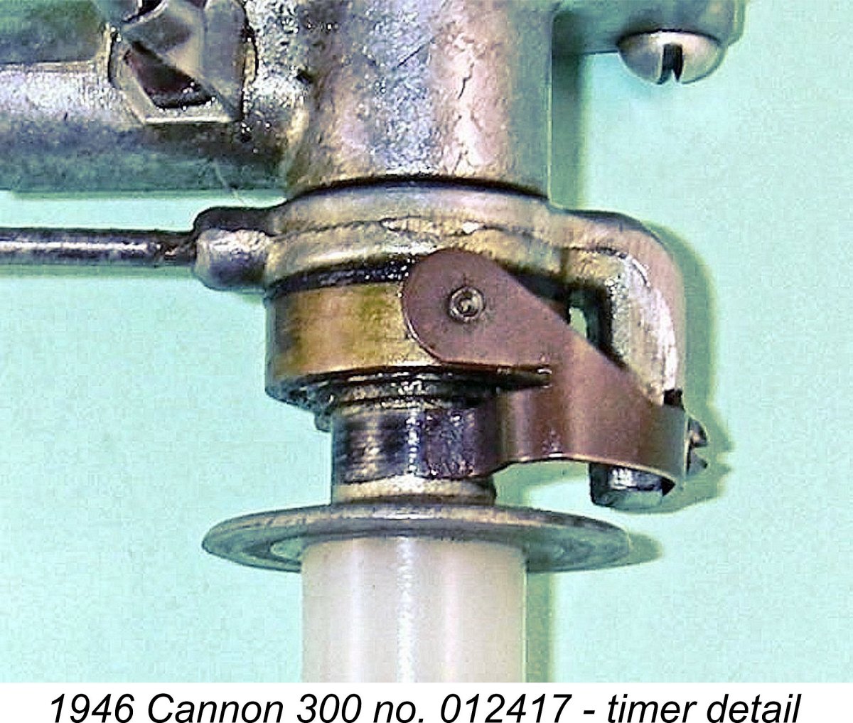 end of the one-sided needle tension spring. This provides unusually positive two-way tension in operation, assuring excellent stability of the needle while the engine is running. The needle is equipped with a long flexible extension with a knurled control knob at its end. A small clip is attached to the cylinder with a machine screw to keep this control knob in a very convenient location above the cylinder head.
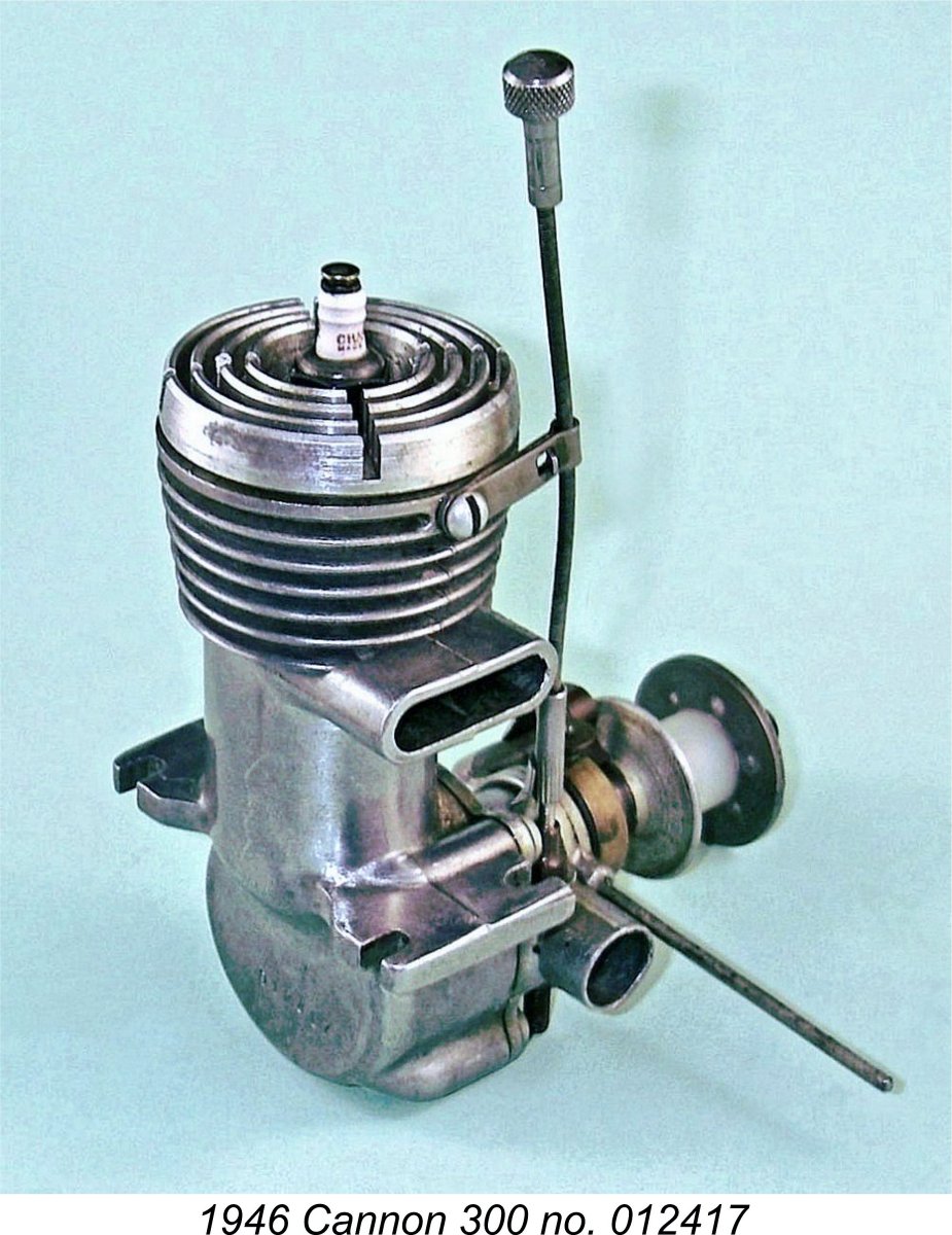 A short dwell period conserves the life of the flight batteries, since it minimizes the proportion of running time during which the points are closed and current is flowing to the coil from the batteries. However, it also makes the engine more susceptible to ignition problems caused by point "float". In addition, it limits the maximum speed at which the engine can be run because at higher speeds there's insufficient real time for the coil to become electro-magnetically saturated, as it needs to be to provide a good hot spark.
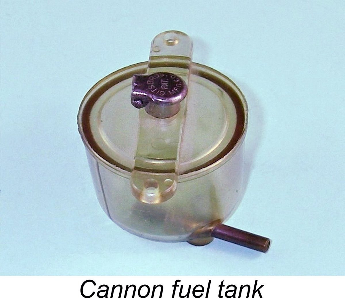 The Cannon engines were supplied with a Champion V2 long-reach spark plug and a separate plastic tank which was clearly designed to be mounted on the same bearers that supported the engine. Early examples were also supplied with a coil and a matched condenser, but these latter accessories were omitted from later offerings, the promotional leaflet information being modified accordingly. The engines were priced at $19.75 and $21.50 for the 300 and 358 respectively.
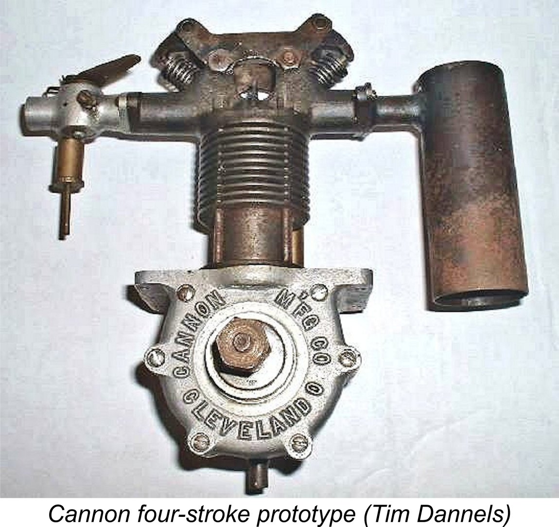 At some indeterminate period, the Cannon company experimented with a large overhead valve (OHV) four-stroke model. Details of this seemingly one-off prototype appeared in issue no. 158 (June 2003) of Tim Dannels' indepensable "
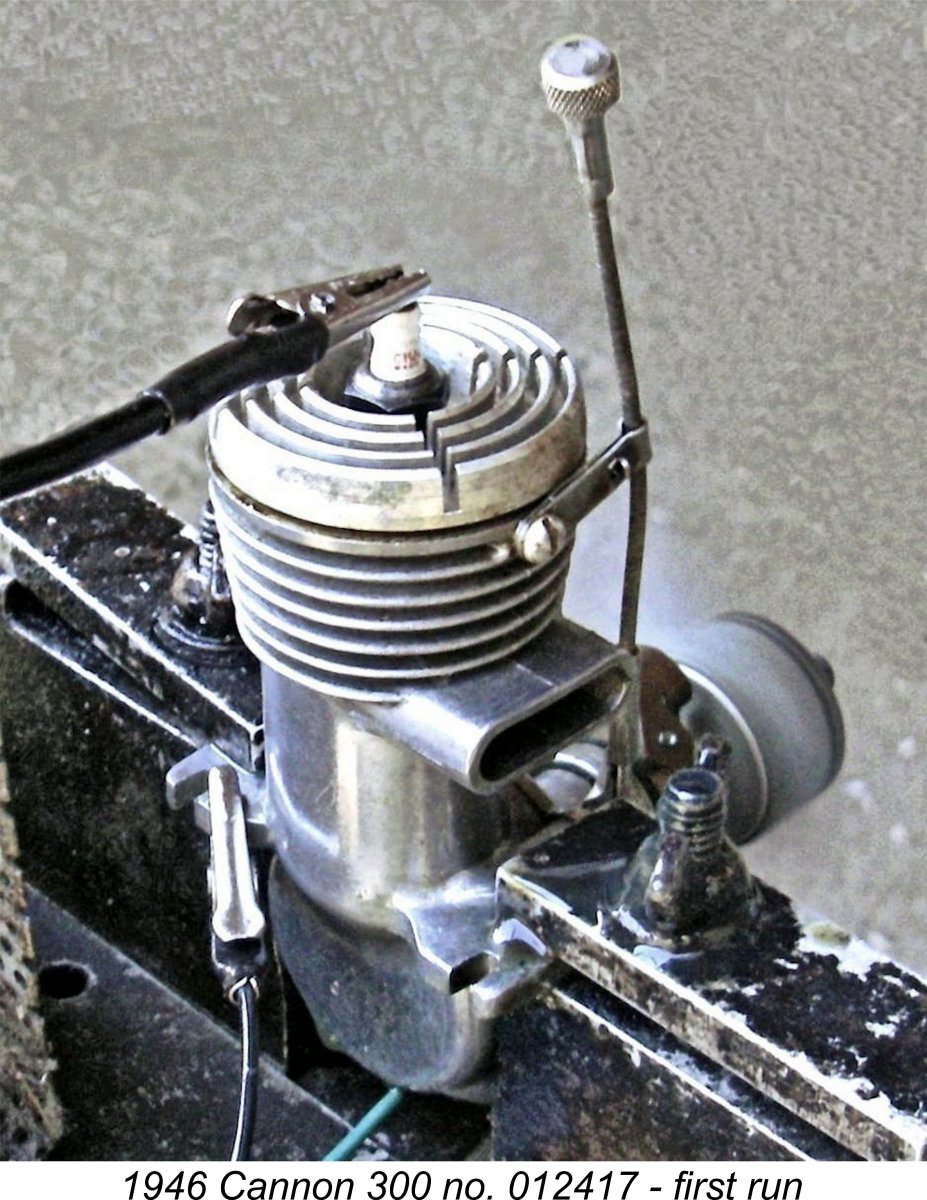 As far as I’ve been able to determine, neither of the Cannon two-stroke models was ever the subject of a published test in the contemporary modelling media. This is another example of the relative neglect of these engines by earlier commentators.
 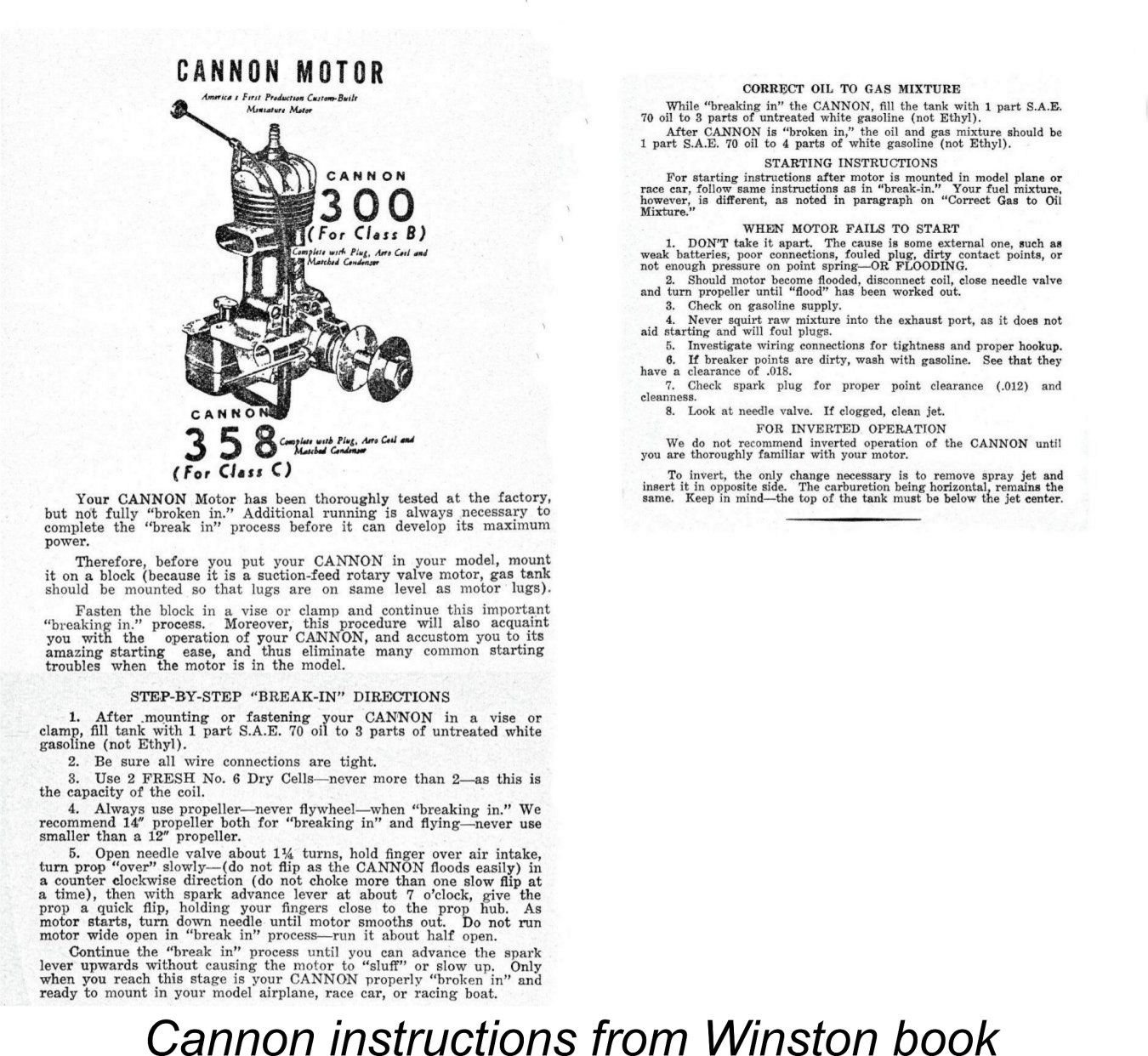 It must be said that the manufacturer's recommendation is very much at variance with the prop sizes suggested by the makers of other contemporary early post-WW2 engines of these displacements. Reference to the tables cited earlier shows that the typical recommendation for a 5 cc (0.299 cuin.) spark ignition engine during the early post-WW2 era was an 11x6 or some close relative – perhaps an 11x8. In fact, many such engines dipped down into the 10 in. diameter range as far as their recommended props were concerned. With its FRV induction system, its high compression ratio, its generous porting and its rational port timing, the post-war Cannon seems unlikely to have been significantly less of a performer than its contemporary 5 cc rivals, most of which would be brought to their knees by a 14x8 prop.
 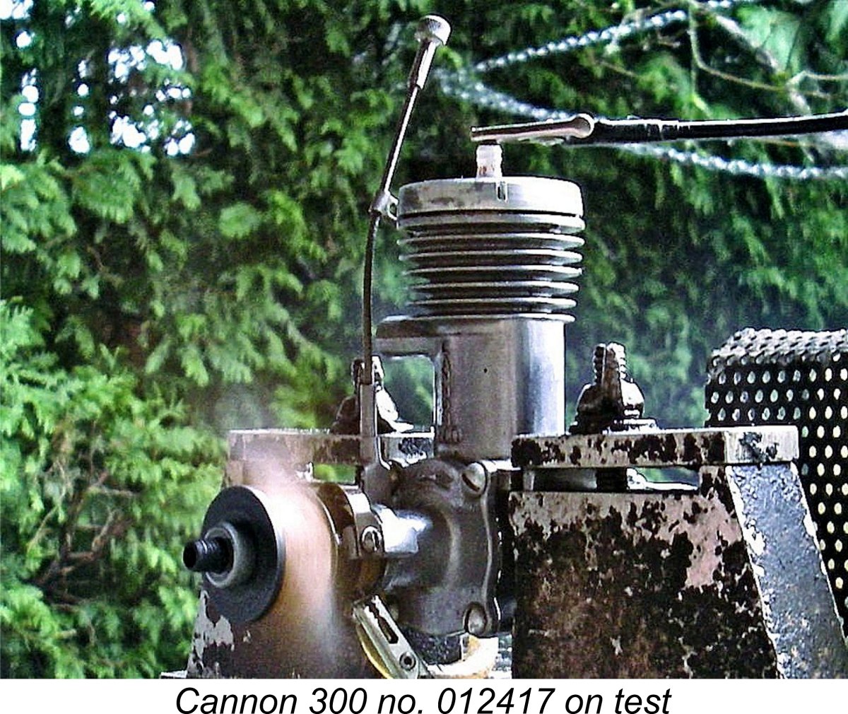 The instructions suggested a needle setting of 1
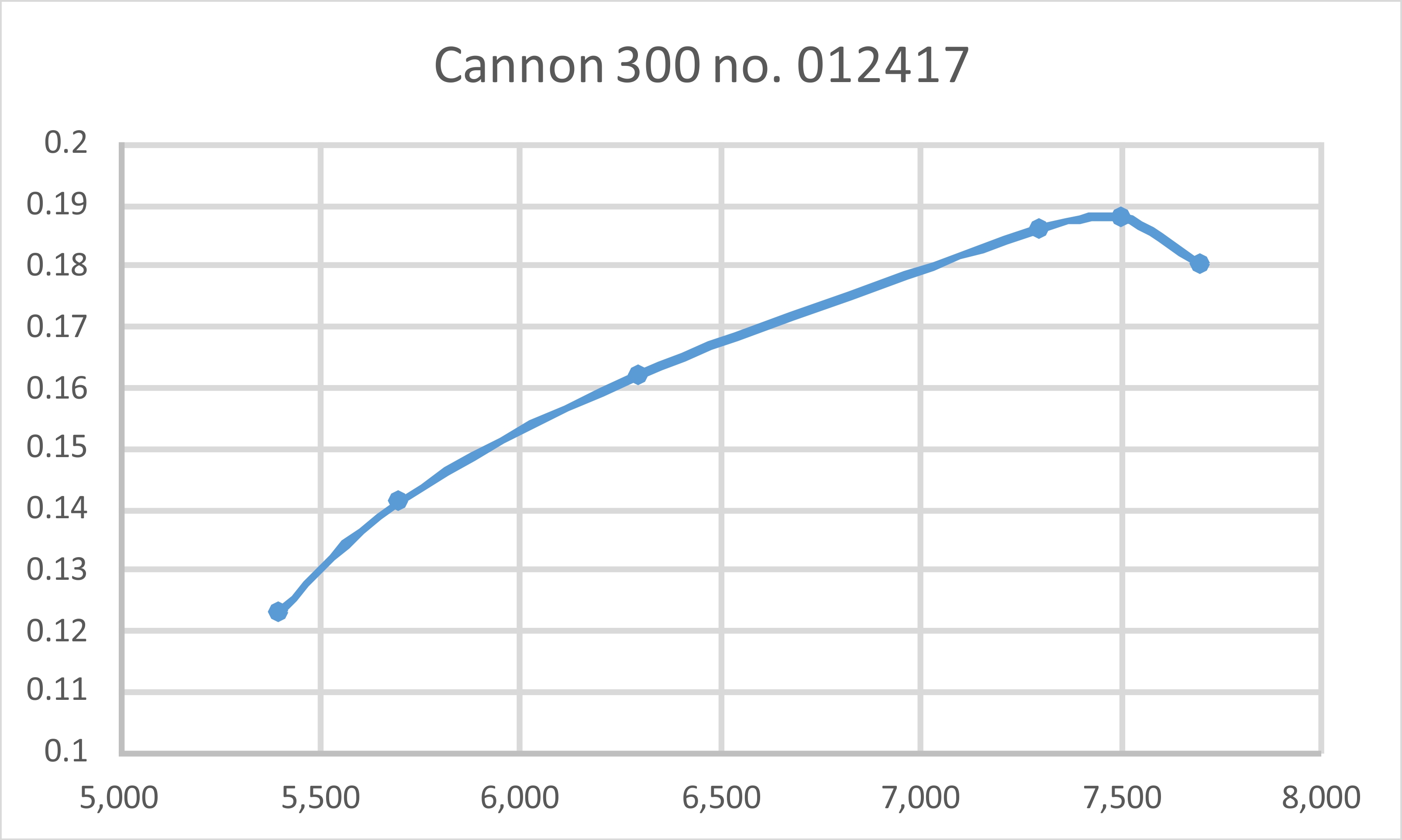
| |