
|
|
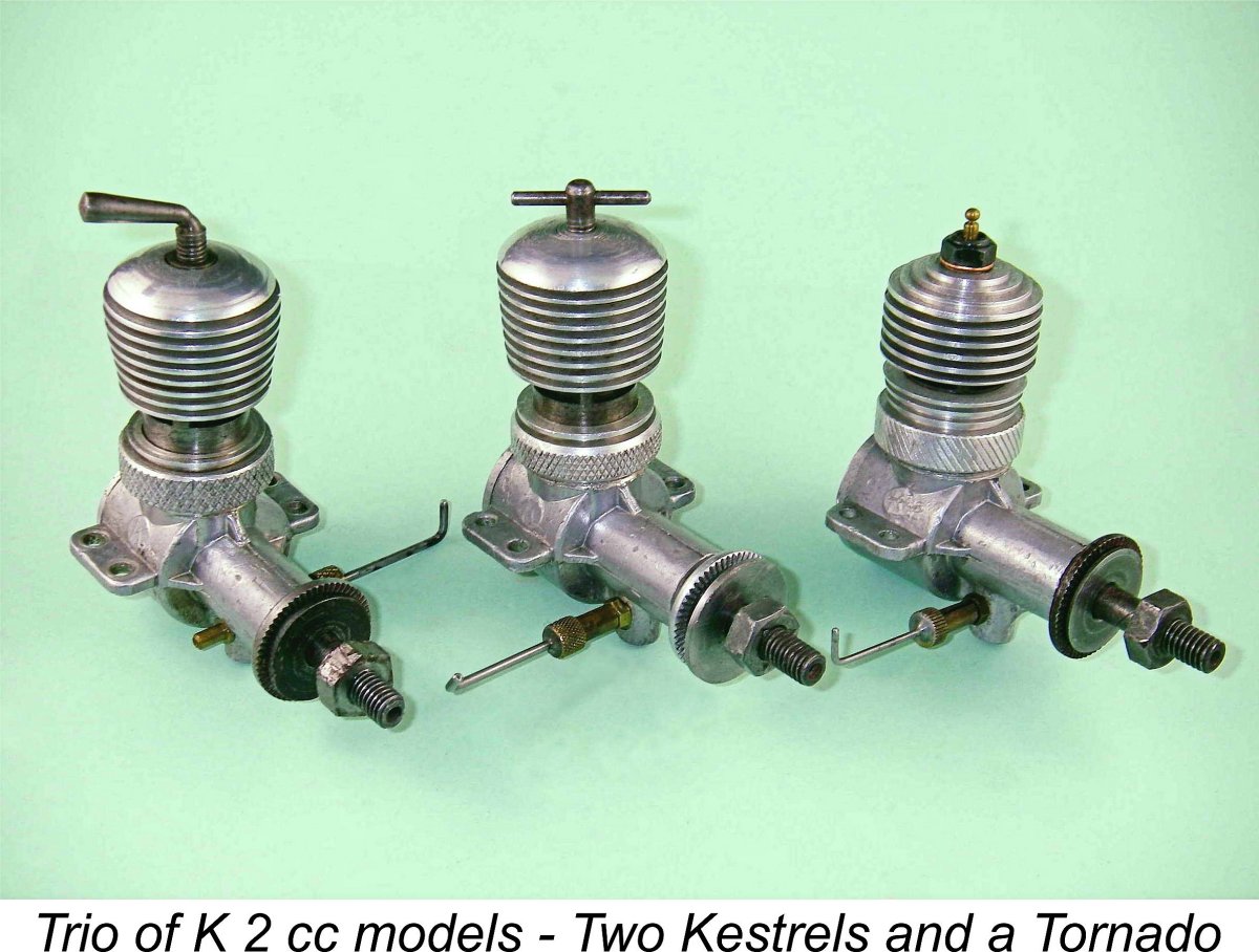
The Kentish "K" 2 cc Trio - the "K" Falcon, Kestrel, and Tornado
Before going any further, it’s necessary to eliminate one potential source of confusion. This is the fact that the far later Aurora model engines from Calcutta, India were also marketed under the K designation, being identified by the letter K followed by their displacements in cubic centimetres. The use of the letter K in that case stood for the Kumar family which was responsible for the development of the Aurora range. The important point to note here is that the early post-WW2 "K" range from Gravesend now under discussion and the later K-series engines manufactured in India have absolutely no connection whatsoever, sharing only the use of the letter K for different reasons. I’ve covered the Aurora/Kumar story in detail in a separate article to be found on this website. Returning now to the "K" engines from late 1940’s Gravesend, in my companion article on the Kemp Hawk I covered the history of the British model engine manufacturing concern founded in 1946 by Harold Kemp as Kemp Engines and continued up to late 1950 under the name of the "K" Model Engineering Co. I’ve also taken an in-depth look at all of the other engines which were produced by this manufacturer, including the 4.4 cc K4 diesel which started it all, the various Kemp and "K" 1 cc models and the 5 cc "K" Vulture which sadly did so much to compromise the reputation of the "K" range. The completion of my coverage of the range required that I take a look at the series of engines in the 2 cc (0.12 cuin.) displacement category which together constitute one of the best-remembered product lines of the "K" Model Engineering Co.
The present topic is a case in point. The new information in this instance included the authoritative identification of a previously-undocumented "K" model based on the Falcon, which is one of the units featured here. I have also been able to substantially refine my understanding of the historical context and sequence in which these engines appeared. This updated information absolutely requires inclusion in any comprehensive and authoritative article about the "K" 2 cc series. The only way that I can accomplish this is to do what I’ve now done - remount the article here with the new information duly incorporated.
First, I wish to acknowledge my indebtedness to my late and much-missed Aussie mate David Owen for his invaluable assistance in researching serial numbers and providing images of engines of which I do not possess examples. Similarly, I'm greatly beholden to my late English friend and fellow Kemp/"K" enthusiast Paul Rossiter for his help in clarifying a number of matters in connection with this study. A special acknowledgement is also due to my late Aussie mate Ron Chernich, both for his efforts in extracting advertisements from his extensive collection of old "Aeromodeller" magazines and for his editing and publication of the original article. My good friend and valued I’m particularly indebted to my friend Dave Causer of England, since it was Dave who finally confirmed the existence of a nominally 2.5 cc "Special" version of the "K" Falcon. It was primarily this confirmation that created the need to publish this updated article. The existence of such a model had been hinted in the advertising - I even mentioned it in my original article - but the absence of any known examples at the time gave it the appearance of being more of a promotional teaser than an actual production item. Thankfully, Dave was able to put this question to rest - the 2.5 cc variant did indeed exist! In fact, additional examples have since been identified. Read on to learn more ……….. Further much-valued assistance came from long-time Kemp/"K" user Brian Cox, who was able to add significantly to our knowledge of the serial numbers associated with the Kemp and "K" engines. Finally, it would be difficult to overstate my gratitude to my English colleague Alan Strutt for generously making available fine examples of both the later variant of the "K" Kestrel and the rare "K" Tornado glow model for inclusion in this study. Without assistance of this nature, it would not be possible to make any claim to authority or completeness for these articles. Now, before we turn our focus onto the series of engines in the 2 cc category which were manufactured by the "K" Model Engineering Co., it may be helpful to new readers to present a brief summary of the chain of events leading up to their introduction. Readers requiring the full details are advised to read the background section of my companion article on the 0.2 cc Hawk. Conversely, those not requiring such information are invited to skip the following section altogether. As always, it's your choice ………. Background
Harold Kemp's new company established premises at 7 Bank Street in Gravesend, more or less right next door to Kemp's new residential address at 3 Bank Street. The business commenced operation on a very small scale, initially employing only three full-time workers (including Harold Kemp himself) plus one part-time assistant. The first definitely-attributed Kemp product was a 4.4 cc sideport diesel called the K4, which was released to the market in early 1947. A detailed article about this model may be found elsewhere on this website.
In early 1948 the company released perhaps its most famous model, the cute little 0.2 cc Kemp Hawk Mk. I sideport diesel. Shortly thereafter, the FRV 1 cc model was replaced by a simple sideport 1 cc design based very much on the Hawk. This was named the Eagle, in keeping with Kemp's evolving "bird of prey" nomenclature. This design too is covered in a previous article to be found here. All of these engines were relatively expensive, although quality was high. Production figures were quite small by comparison with those achieved by the more prominent British manufacturers of the period such as E.D., Mills Brothers and International Model Aircraft (FROG). However, the range acquired a good reputation for being well-made and dependable, thus representing good value for money. Consequently, both the Hawk and the Eagle appear to have sold as fast as the tiny company could make them. It must soon have become clear to Harold Kemp that the potential for increased sales was considerable. The key to tapping this potential lay in expanding production capacity, thereby also reducing unit production costs.
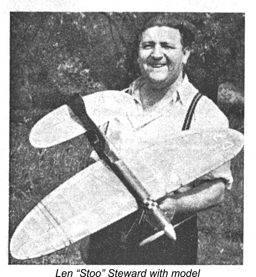
It seems that Len Steward was in control of the re-named company from the outset. It's presently unclear whether or not Harold Kemp retained a connection with the operation, but it's entirely possible that he did so. He certainly continued to reside at 3 Bank Street in Gravesend until at least late 1951, well after the closure of the "K" Model Engineering Co. The new company seems to have come into existence in around July of 1948, since it was mentioned in the July 29, 1948 issue of "Model Engineer" and its first paid advertisement (reproduced above) appeared in the August 1948 issue of “Aeromodeller” magazine. That As mentioned earlier, Len Steward was a leading member of the very active West Essex club, becoming a prominent participant in major control-line stunt contests at the time in question. With this background, it should come as no surprise to learn that his influence over the company's affairs was very much directed towards the development of engines suitable for stunt use. This made complete business sense, since control-line stunt was probably the fastest-growing branch of the aeromodelling hobby in England during this period. How times change…………... In order of their appearance on the market, the first new products of the "K" Model Engineering Co. were an updated version of the sideport Hawk (c. September 1948), a 5 cc FRV diesel called the Vulture (October 1948) and a Mk. II version of the 1 cc Eagle featuring FRV induction (December 1948). The Eagle Mk. II was also offered in kit form, a not-uncommon marketing strategy during the cash-starved period which the British economy underwent followed the conclusion of WW2.
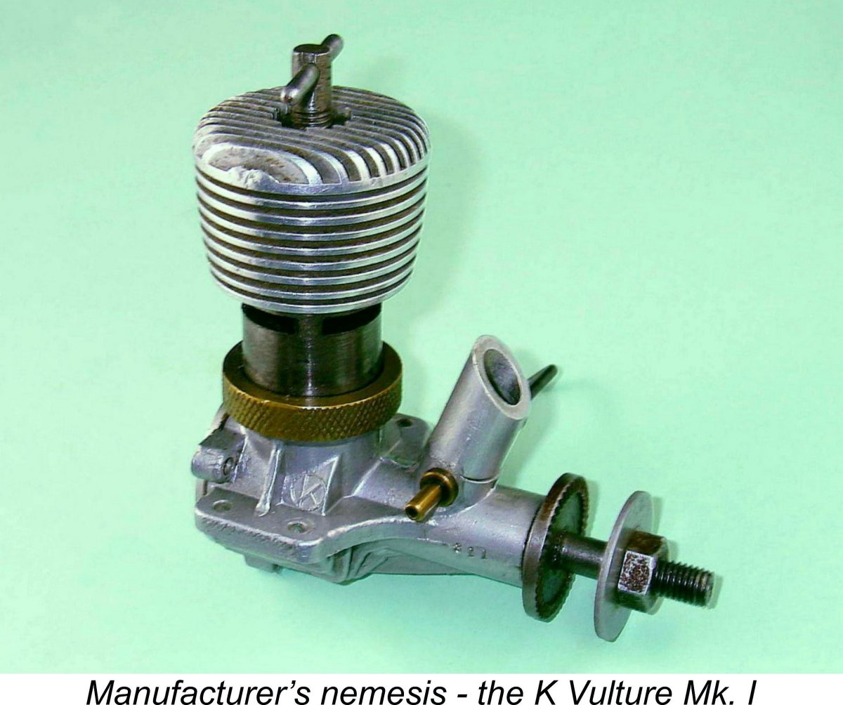
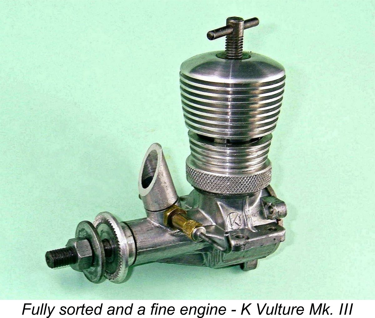
The company quickly made design changes to address the structural deficiencies, substantially improving both the durability and performance of the resulting Mk. II Vulture and its Mk. III "Competition Special" successor. However, their efforts appear to have been insufficient to revive the fortunes of the Vulture in commercial terms. They had evidently anticipated a strong demand for this engine and had set their staffing levels and production quotas accordingly. The fact that the anticipated buyers did not materialize left them with a growing inventory of unsold examples. Since they had already borne the cost of manufacturing these units, a considerable amount of their capital was now tied up in unsold inventory - hardly a healthy situation from a fiscal standpoint. From This was a great pity, because a well set-up late-model Vulture is actually a perfectly useable and durable engine in the hands of a capable operator, undoubtedly making a very good stunt diesel by the standards of its day. As a Vulture user himself (with some competition success), Len Steward was doubtless well aware of this. He seems to have decided that one way to demonstrate the basic soundness of the revised Vulture design and also restore the company's credibility was to release a smaller version of the engine in a more "popular" displacement category. Such a model would benefit in design terms from the lessons learned with the Vulture and would be easier to handle. Moreover, the smaller engine would have broader sales appeal given the related facts that it could be sold at a lower price; could be used with smaller and less expensive models; and would be far easier on the fuel budget - all important factors in cash-starved early post-war Britain.
At this point, some readers may be asking themselves - "Why 2 cc?" No doubt a somewhat odd displacement from a present-day standpoint, but this is a matter which has to be considered in a late 1940's context as opposed to a twenty-first century one. At the time in question, the "magic" displacement of 2.5 cc (0.15 cuin) had not yet been adopted by the FAI for International competition. Accordingly, no particular displacement really had much of an edge over another. The only issues were what size of model was desired and whether or not a given engine could do the job of flying that model to the required standard.
Seen in this 1949 context, there was actually nothing at all extraordinary about the "K" Model Engineering Co. releasing what was intended to be a "popular" new model in the 2 cc displacement category. It was only later, when the 2.5 cc limit was formally adopted by the FAI and the British ½A displacement limit was set at 1.5 cc, that the attention of manufacturers became progressively more focused on engines built to the new competition limits and the 2 cc displacement category became something of an orphan, lying between competition classes. Now that the background to its introduction has hopefully been made clear, let's take a closer look at the Falcon. The "K" Falcon
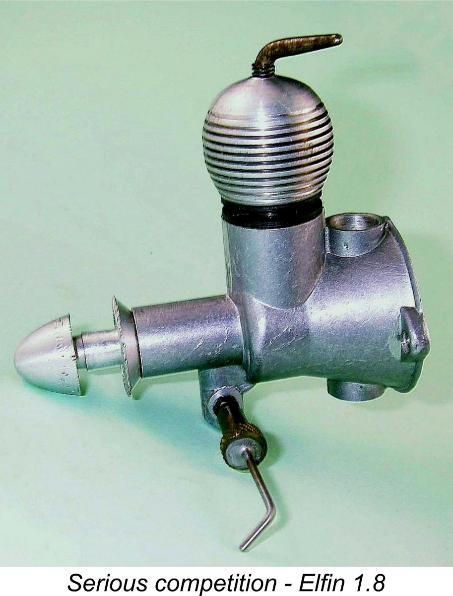
In most important respects, the Falcon was simply a scaled-down version of the companion 5 cc Vulture Mk II. Note that the strengthened crankshaft and conrod of the Mk. II Vulture were highlighted, since it was predominantly failures of those two components that had destroyed the Mk. I Vulture's reputation along with that of the company. The Falcon featured the same ultra-simple construction in which no screws were used, all the parts being of the screw-in or screw-on type. The entire engine consisted of only 17 individual components, and three of these (the prop nut, prop washer and spraybar nut) were off-the-shelf items that did not have to be manufactured. Apart from being introduced in the shadow of the earlier Vulture failures, it was also perhaps the Falcon's misfortune to arrive on the scene at a time when it faced formidable opposition from a well-established direct competitor in the shape of the Elfin 1.8 cc radial mount plain bearing model. This ground-breaking design had appeared in the latter half of 1948 as a replacement for the earlier 2 cc Aerol Hurricane and was taking the British modelling world by storm at the time. The Falcon shared a number of features with its rival, including the radial cylinder porting and the use of updraft FRV induction. It's hard to say whether this would have enhanced or diminished the marketplace view of the engine, but it would certainly have made direct comparisons inevitable.
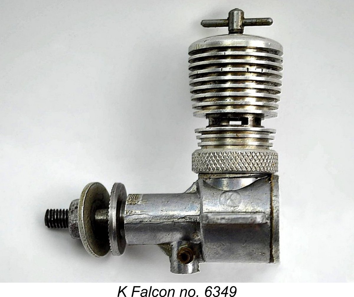
To offset this, the Falcon was the clear loser in term of weight, tipping the scales at 4.3 ounces, just over an ounce heavier than the 3.25 ounce Elfin. But the simplicity of its construction allowed the makers to offer the engine for sale at a very competitive price of £2 19s 6d (£2.97), which presented a notable contrast with the £3 19s 6d (£3.97) price tag of the competing Elfin. So despite its weight disadvantage, the Falcon appeared on paper to offer quite serious competition to its Liverpool rival. Looking now at the engine's construction, I find myself largely repeating my description of the Vulture which appears elsewhere. The case-hardened steel cylinder was of basically tubular form - the step down in outside diameter just above the exhaust ports which was a feature of the larger Vulture was omitted in the smaller model. The upper portion of the cylinder was externally threaded to accommodate the screw-on machined alloy cooling jacket. The lower end below the ports featured a base flange which served to locate the cylinder vertically on top of the crankcase. A thin gasket between the cylinder base flange and the upper crankcase ensured a good seal. As with the Vulture, there was no "spigot" length below this flange to locate the cylinder laterally on the crankcase. Instead, the cylinder was both secured and laterally The dog collar on the Falcon was modelled very closely upon the matching item used on the contemporary Mk. II Vulture. It was a light alloy item having an upward tubular extension to a point just below the exhaust ports. This extension carried a set of shallow turned cooling fins. Given their location, these could have had little practical effect and were doubtless more for show than anything else. The upper cylinder was equipped with a conventional contra piston made of hardened steel. This is normally a problematic choice of material for use in a steel cylinder since in most cases a steel contra-piston freezes solid in a steel bore after the engine warms up a bit. Some of the "K" 2 cc engines do exhibit this behaviour, and a cast iron contra piston would undoubtedly have been a better choice. If you ever have occasion to fit a new contra piston to one of these engines, use cast iron! The fully-machined screw-on aluminium alloy cylinder jacket featured a smooth head, in contrast to the finned head of the Mk. II Vulture. This configuration was shortly to appear on the Mk. III version of the Vulture as well. The omission of head fins was doubtless a cost-cutting measure. The jacket featured integrally-machined barrel fins of conventional pattern. Unusually, the thread for the compression screw was not formed directly in the centre of the head - instead, the cylinder was topped by a hard brass disc with a central spigot which engaged with an oversized hole in the centre of the head. This brass disc was sandwiched between the underside of the head and the top of the cylinder when the jacket was screwed down. The thread for the comp screw was formed in the brass spigot rather than in the head itself. These arrangements were carried over directly from the Vulture. The presence of this component doubtless contributed to the relatively high weight of the Falcon and also made the engine somewhat taller than it would have been otherwise. However, it did have the advantage of permitting a worn comp screw thread to be rectified simply by replacing the brass insert rather than the entire cylinder jacket.
This system did not provide much in the way of either velocity or directional control of the incoming mixture, and in the case of the larger Vulture it clearly resulted in substantial losses of unburned mixture through the exhaust ports. It's reasonable to expect that the Falcon would be similarly afflicted, and indeed a well-trained "diesel nose" can detect the unburned fuel in the exhaust of a well-tuned Falcon or its successors. The conical-topped piston was again of hardened steel and was used in conjunction with a hardened steel connecting rod. The rod was of quite substantial proportions - the designer had clearly learned from his sad early experiences with the Vulture! Unusually once again for a British engine, the piston and rod were connected by a ball-and-socket joint rather than the more conventional gudgeon pin arrangement. This system had in fact been introduced to British model diesel manufacture in the former Kemp Eagle Mk. I sideport diesel and had also been applied to the Vulture and the 1 cc K Eagle Mk. II. It was thus something of a Kemp/K trade-mark feature by this time.
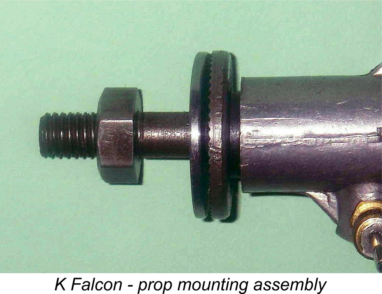
Thankfully, this is not by any means a barrier to the refurbishment of one of these engines. My friend and colleague Dave Causer has developed a very practical design for a set of replacement components of more conventional pattern. Full details of Dave’s system may be found elsewhere on this website. The hardened steel crankshaft was of conventional form and appeared to be adequately sized for the job, in contrast to the matching component on the Mk. I Vulture. The crankweb was of the full disc type but lacked the substantial counterbalance which was a feature of the companion 5 cc Mk. II and Mk. III Vultures. The shaft ran in a well-fitted steel bushing which was pressed or shrunk into an alloy housing cast integrally with the main crankcase. A round crankshaft induction port was used in conjunction with a venturi base of similar shape formed in the bushing. It’s very clear that the Falcon designer was anxious to avoid the fragility issues which had bedevilled the working components of the original Vulture. Crankshaft journal diameter was a nominal 5/16 in. (0.312 in.), only 1/16 in. less than the diameter of the same component in the 5 cc Vulture shaft and a quite generous figure for a 2 cc diesel. The shaft in a checked example actually measured up at 0.315 in. So far so good, but the central hole for the passage of incoming mixture had a checked diameter of an equally generous 0.200 in., resulting in a crankshaft wall thickness of only 0.058 in. - roughly the same as that of the Mk. I Vulture shaft which had given so much trouble. However, the fact that the K 2 cc engines The steel prop driver was secured to the shaft by being pressed onto a short splined section of shaft forward of the locating shoulder. A standard prop nut and prop washer were used to secure the prop against the driver. Somewhat unusually, the thread used was 0 BA! If a need for a replacement prop-nut ever arises, this is almost exactly equivalent to a standard 6 mm x 1.0 mm metric thread. Looking now at the main casting, the 28 TPI threads on the upper part of the case onto which the dog collar screwed were apparently formed using a large Coventry die-head. This forced the designer to keep the rest of the casting below the level of these threads so that nothing would foul the die-head. This was likely a significant factor in the choice of updraft induction since it placed the venturi on the opposite side of the main casting from the cylinder retention threads. The venturi itself had a nominal bore of 0.1875 in. (4.76 mm). This may appear a little skinny for a 2 cc engine, but it was used in conjunction with a spraybar which was thinned across its working length to a thickness of only 0.110 in. (2.80 mm). These components combined to give good gas velocities and hence excellent suction, a real asset for a diesel intended for stunt use. According to Maris Dislers’ extremely useful Choke Area Calculator, this combination will provide adequate suction at all speeds above 5,524 rpm. The component sizing thus seems entirely appropriate. The needle was quite conventional, utilizing the standard split thimble setup for tension. The spraybar thread was 5 BA. The main bearing housing on the Falcon was of generous proportions and was quite sturdily braced at four locations at the point where it met the front of the crankcase. However, the mounting lugs remained something of a weak point with the Falcon, as they had been with the Mk. I and Mk. II versions of the Vulture. They were somewhat thinner than ideal for an engine of this size and were in fact less substantial than those on many engines of significantly lesser displacement. Moreover, the Falcon did not have the benefit of the centrally-located stiffening webs or the forward extensions which had been features of the Vulture. Overall, it has to be said that the lugs on the "K" 2 cc engines appear somewhat marginal for the job, and it’s undeniably true that cases with damaged lugs are not infrequently encountered. When flying these engines myself, I have always used small plates of 1/8 in. aluminium alloy which are shaped like the lugs in Returning to our description, the backplate was a simple screw-in item turned from solid aluminium alloy bar stock. It sealed to the rear of the case with a gasket. An additional radial mount backplate was supplied for the Falcon as an accessory. Radial mounting was enjoying something of a vogue in Britain at the time, largely one suspects as a result of the great success of the early FROG engines and the Elfin 1.8 cc model. Even minor contemporary manufacturers such as Dyne and M.S. went with radial mounting on their engines. The "K" Model Engineering Co. hedged their bets by featuring beam mounting as standard, with the option of radial mounting if desired. This was another factor which might have been expected to give the Falcon something of a marketplace edge over the radial-only Elfin. I have to say that the Falcon's crash resistance would be far higher with a radial mount.
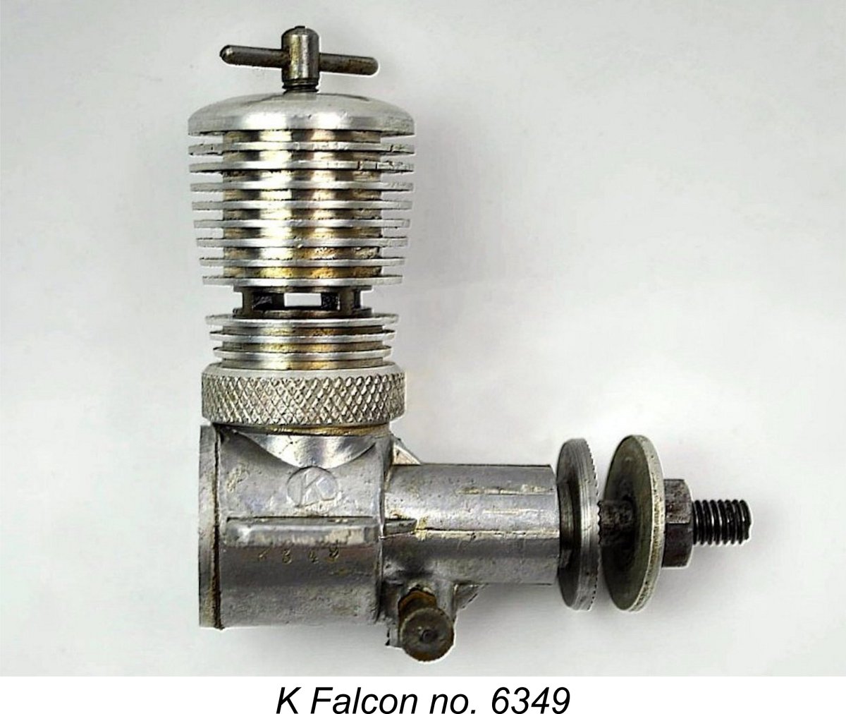
Thanks to the splendid cooperation of my colleagues acknowledged at the outset, I’m fortunate enough to have access to a highly representative sample of serial numbers for the Falcon. It's evident from the numbers recorded to date that the Falcon received its own distinct serial number sequence beginning with engine number 6001 - all authenticated numbers reported so far are within the 6xxx range, with no letter prefix. The earlier 1 cc Eagle Mk. II FRV model had been numbered in the K5xxx series but had been discontinued at around the same time as the introduction of the Falcon and never approached numbers in the K6xxx range in any case. Serial numbers for the other contemporary K models were nowhere near the 6000 mark, nor likely to get there, making it pretty clear that the intent was to keep the numbers on the Falcons quite distinct from those of other models in the range. At present, the lowest 2 cc Falcon serial number of which I’m aware is 6045, while the highest is 6979. This seems at first glance to confirm that perhaps 1000 examples of the original 2 cc Falcon were produced. However, this figure may be somewhat exaggerated - see further discussion below. Regardless, such a figure is certainly consistent with the fact that the Falcon is significantly less common today than its successor, the "K" Kestrel, which we will examine in a following section of this article. It turns out that my illustrated example number 7462 is an example of the 2.5 cc Falcon Mk. II "Competition Special". That model will be discussed separately in due course.
As an interesting aside, I subsequently acquired this very engine from the estate of my late and much-missed friend Paul Rossiter. It turns out to be a mint example of the Falcon in every respect apart from the case, which bears that K349 number. It also seems to be unmounted and un-run. That being the case, I'd say that the second of the above two possibilities is most likely correct - it's an original Falcon which has received some damage to the case (probably those skimpy mounting lugs) and has had a replacement unused Kestrel case fitted. The conversion of seemingly unused Kestrel no. K349 would have required the possession of more original Falcon parts than I can readily see some owner having on hand, nor can I see much point in such an exercise. The Falcon remained on the market for some 10 months, making its final featured advertising appearance (as far as I’m presently aware) in the February 1950 issue of “Aeromodeller” magazine. It continued to appear on the order form which was included with the advertisements until May 1950, after which no more was heard of it. During its marketplace tenure, it had demonstrated good potential in the control-line stunt field, powering the 4th place model in the 1949 Gold Trophy as well as finishing 3rd in the control line stunt category at that year's prestigious West Essex Gala. In both instances, the models were flown by Len Steward, promoting his own product in the best way possible. Sadly, these successes had not translated into increased sales activity for the company. No test of the Falcon ever appeared in the pages of "Aeromodeller" magazine. However, the engine did attract the attention of the resident engine tester for the rival magazine ”Model Aircraft” (almost certainly Peter Chinn). Let's see how the engine fared in his hands .............. The "K" Falcon On Test The Falcon made its one and only published test appearance in the January 1950 issue of “Model Aircraft.” For reasons which remain unclear, the magazine did not publish the name of the individual responsible for these tests at the time in question or for many years thereafter. However, there's an overwhelming body of circumstantial evidence to support the conclusion that the tester was Peter Chinn, who contributed regular articles on model engine development to the magazine. Since to my knowledge no-one has ever presented a credible challenge to this conclusion, I have always upheld the identification of Chinn as the author of this and other unattributed “Model Aircraft” tests. If anyone can prove me wrong, let's see your evidence! Chinn (assuming it was he) reportedly had two examples of the Falcon available for test, both obtained directly from the manufacturers. However, one of these had evidently been assembled very much on the tight side, hence being reluctant to perform with any great authority. The fact that all of the working components were made of hardened steel meant that a tightly-fitted engine would take many hours of running to free up, an expensive process in terms of fuel costs and one which the average modeller would quite reasonably not expect to have to face. Chinn's other example was evidently fitted considerably less tightly and performed far better than its companion right out of the box. It was this engine that was used as the basis for the major content of the report. It was given a one-hour running-in period and was then tested in the usual manner. There is an implication in the above findings that there was considerable variation in quality between different examples of the Falcon. If this was a common issue, there's little doubt that some buyers must have been quite disappointed. This would scarcely have furthered Len Steward's objective of restoring consumer confidence in his company's products following the Vulture debacle. We'll be recalling this factor in a later section of this article.
Another factor which could potentially affect starting is the width of the transfer port (the entire circumference of the bore). Such a wide port would tend to result in reduced transfer gas velocities, a characteristic which is not conducive to good starting. The larger Vulture suffered noticeably from the effects of both factors cited above. Having made the above statement, Chinn softened the blow by stating that "neither Falcon presented any operational difficulties under test". My own latter-day experiences bear this out completely - the "K" 2 cc models are among the easiest-starting small diesels of them all in my own view provided one uses the correct approach. Chinn found that once the correct needle and compression settings had been established, little further adjustment was required between starting and running settings. Again, present-day experience bears this out completely. An issue encountered with one of the two engines tested by Chinn was the loosening of the dog collar. This is a typical issue with the "K" engines and is more of a characteristic than a real problem - it's mostly a consequence of the sealing gasket compressing over time, and the assembly does stabilize eventually. All that's necessary is to check periodically to ensure that the collar remains snug. But please preserve the knurled surface of the dog collar by protecting the jaws of the tool or using a strap wrench when doing this!
In comparing the two sets of results, it's worth recalling that Chinn consistently tended to find more power at higher revs than either Sparey or his “Aeromodeller” engine testing successor, Ron Warring, when testing the same engine. This must be down to variations in the testing and engine management procedures. It's likely that Chinn would have extracted a somewhat better performance from the Elfin than Sparey was able to do. My own tests have certainly shown a higher output for the Elfin 1.8 than that measured by Sparey, albeit at a somewhat lower speed. Regardless, on this published showing the Falcon far out-torqued the Elfin, producing greater peak power at substantially lower rpm. It would seem that the Falcon would happily swing a larger and hence more efficient prop than the Elfin. Chinn used an 8x8 airscrew for flight testing, and this is probably a good choice for stunt applications with this very torquey low-revving engine. A useful feature of Chinn's reports at the time was the occasional addition of information based upon actual flight testing. The Falcon was one of the engines tested in this very practical manner. Chinn reported that the better of his two Falcons was mounted in a small control-line stunt model of 150 square inch wing area that had originally been built for "a well-known Class "A" diesel of rather smaller capacity". The overall weight was increased by less than one ounce to 9½ ounces for a still quite practical wing loading of 6.27 ounces/100 sq. in. Chinn reported that using an 8x8 airscrew and flying on 40 foot lines, the model's speed increased from less than 40 mph to almost 52 mph, and the "feel" of the model during manoeuvres was greatly improved. He was clearly quite impressed by the Falcon's airborne performance in this application. He doesn't appear to have experienced any mechanical difficulties over the course of what was clearly an unusually arduous test.
This was the only test of a "K" product that was destined to appear in “Model Aircraft”. Somewhat unusually, the rival “Aeromodeller” magazine never published a test of the Falcon or any of its successors. This appears to be the right place in which to insert a little of my own operational advice based on years of experience. It's easy to forget that the location of the spraybar on this updraft design requires that the tank be set considerably lower than usual to keep the starting fuel level more or less on par with that of the spraybar. Assuming the usual upright mounting position in a test stand, a tank set at the "normal" elevation relative to the overall engine will give rise to gravity fuel feed, much of which will drip straight out of the intake or will create a potential flooding problem if the engine delivers a firing burst on a rich needle just as a drip is forming. The engines don't like to be too "wet" for starting, because any excess fuel in the cylinder goes straight down the bypass passages to pool in the crankcase. This can easily lead to flooding. The best results are achieved with the fuel level matched to the spraybar elevation and the administration of a dry prime (with the exhaust ports closed). A single choked flick to fill the fuel line, followed by a dry prime, and the engine usually starts with just a couple of flicks. The 2.5 cc "K" Falcon Mk. II “Competition Special”
The application of this dual-variant marketing strategy to the Vulture seems to have got the company thinking about a similar approach to other models in their range. In June 1949 they announced a Mk. II "Special" variant of the recently-introduced FRV 0.2 cc "K" Hawk Mk. II, although it's presently unclear whether or not this actually reached production - I’m aware of no surviving examples. In reality, it was probably nothing more than a cosmetically-reconfigured "K" Hawk Mk. II. The company then turned their attention to the Falcon. It’s apparent that although the Falcon was manufactured in substantial numbers at the outset in anticipation of a strong demand, that demand never materialized. This quickly led Len Steward to investigate ways in which the seemingly excessive unsold stocks of the engine or its components might be re-manufactured into units having a broader appeal to potential customers. This strategy appears to have been initiated by July 1949, the first result being the August 1949 advertising debut of a previously-unreported model - the 2.5 cc "K" Falcon Mk. II "Competition Special". This advertisement is reproduced above. The new model sold at a price of £3 9s 6d (£3.47) - some 10 shillings (£0.50) more than the companion Falcon 1.96 cc model, which remained on offer.
Since the enlarged Falcon looked exactly like its smaller brother, it requires a very close examination to distinguish between the two models. Consequently, there are undoubtedly a few more of them out there that have never been identified as "Competition Specials" - worth checking (as I did) if you own a Falcon, especially one with a serial number over 7000! Maris Dislers has pointed out that if the cooling jacket is unscrewed a little, the piston diameter can be measured through the exhaust ports using a vernier caliper. Dave Causer’s example (no. 7006) was found to have the same 14.27 mm stroke as the standard 1.96 cc Falcon but a larger bore of 14.64 mm (up from 13.21 mm) for an actual calculated displacement of 2.40 cc. This highlights one of the oddities associated with the Mk. II Falcon. There's an unusual degree of variation in the bore dimensions of different examples. My engine number 7462 has a bore of exactly 14.50 mm, while Dave Causer's engine number 7006 has a 14.64 mm bore. To compound this issue, engine number 7097 reported by Maris Dislers has a bore of 14.74 mm. Go figure!! The calculated displacements range from 2.36 cc to 2.44 cc. The average is 2.4 cc, so that's probably the right figure to associate with this model. Another variation is to be found in the crankpin diameters. The original 1.96 cc Falcons and the early 2.4 cc Mk. II examples have 0.1875 in. dia. crankpins, while several later Mk. II units have smaller crankpins having diameters of only 0.156 mm. This change was presumably made to allow for the use of a thicker-walled big end bearing. Looking through the various advertisements for the K engines, Dave confirmed that the nominally 2.5 cc Falcon first appeared in the manufacturer’s August 1949 advertising placement reproduced above. This I thought initially that the larger-displacement model was probably created by the simple expedient of taking a previously-manufactured unsold example of the 1.96 cc Falcon and boring (or perhaps grinding) its cylinder out to the larger bore noted above. The substantial reduction in cylinder wall thickness is very obvious, as seen at the left. A replacement piston and contra-piston of the required size were then made and installed. While this certainly would increase the displacement, it would also have reduced the bypass depth and area depth quite significantly. It also left a seemingly marginal amount of metal connecting the upper cylinder to the rest of the engine. However, it now appears that my original theory doesn't hold up. Maris Dislers had an opportunity to examine one of these nominally 2.5 cc "Competition Specials", finding that the cylinder is a distinct purpose-machined component rather than a bored-out Falcon part. The broached bypass/transfer ports are cut wider to compensate for their shallower depth, confirming that they were machined with a different tool. It's clear from this that the piston/cylinder sets were made from scratch especially for the 2.4 cc model. Maris was able to confirm that this model reached the Australian market. He sent in a scan of a back cover advertisement from the Myer Emporium of South Australia which appeared in the March 1950 issue of “Australian Model Hobbies” magazine. This included a listing for the "K" 2.5 cc Competition Special, although not specifically by that name. Maris subsequently located two examples in Australia bearing the serial numbers 7097 and 7108.
It seems odd that the "K" Model Engineering Co. advertised two successive 1.96 cc models in fulsome terms but did not promote the 2.4 cc model very energetically. Why, for example, did they not send one of the larger variants to Peter Chinn for testing, along with a standard Falcon? Maris Dislers speculated that perhaps the larger-bore 2.5's had a tendency to "blow their top" or suffer unacceptable levels of crash damage due to their minimal residual cylinder wall area at the exhaust bridges. Such issues would not have helped the already-tarnished reputation of the "K" model engine range. All four presently-reported confirmed Falcon 2.4 cc Mk. II serial numbers lie in the 7xxx range. This makes it appear possible that the 7xxx serial number range was reserved for the nominally 2.5 cc Specials, which were created using Falcon cases fitted with the big-bore piston/cylinder sets. However, the switch to the Mk. II version may have occurred prior to that point being reached - the two Falcons numbered 6904 and 6979 may also have been Mk. II's for all we know. At the upper end, my own now-confirmed 2.4 cc Mk. II Falcon number 7462 (the highest reported number for this model) implies that in all probability at least 500 examples were made. This model may be far less rare than has previously been supposed - the previous impression of mega-rarity may have much to do with most of the Mk. II examples being unidentified as such. The 2.5 cc Mk. II "Competition Special" version of the Falcon evidently outperforms its 1.96 cc predecessor, but not by all that much. In all likelihood, the reduction in bypass area resulting from the boring-out of the cylinder did much to offset any gain which might have resulted from the increased displacement. This was definitely a bit of a band-aid approach to the creation of a new model! Nonetheless, it did offer Falcon or Kestrel owners the option of gaining a little extra flight performance simply by bolting in an example of the larger engine. Maris tested 2.44 cc Falcon Mk. II number 7097, finding that it really didn't perform at a significantly higher level than my own 2 cc "K" Kestrel (see below). This appears to be a consequence of the fact that the makers seem to have used the same venturi and spraybar diameter in both models. This would tend to negate any potential benefit from the 25% greater displacement - the engine may have been induction-limited rather than displacement-limited. The shallower bypass passages would not help either. My very sincere thanks to Dave Causer and Maris Dislers for sharing this information with the rest of us! The "K" Kestrel
The Kestrel was clearly aimed squarely at the "popular" market. It sold for the rather startlingly low price of only £2 5s 0d (£2.25), thus undercutting the Falcon (and the Elfin competition) by a substantial margin. This may have been made possible in part through the use of surplus components originally manufactured for the 1.96 cc Falcon, the production of which had almost certainly ceased by this time. In releasing this model, it might appear that Len Steward was undermining his own efforts to dispose of what appears to have been a significant inventory of unsold Falcons. In effect, he appeared to have been going into competition with himself! However, things weren’t quite that simple. As matters stood, the already-existing Falcons weren’t selling anyway, even without any competition from another model. The Falcon's failure to excite the market was very likely due to the blow to the manufacturer's reputation caused by the problems with the "K" Vulture Mk. I. But whatever the reason, those unsold Falcons (and quite a few unsold Vultures, remember) were generating no revenue sitting on the stock shelves - worse, they represented tied-up capital which was doubtless depreciating over time. The various attempts to enhance the Falcon's saleability had yet to commence. Meanwhile, the company's cash flow was grinding to a halt. Moreover, Steward couldn't afford to continue paying his skilled workforce to manufacture engines that weren't selling. It was clearly imperative both to re-establish some level of cash flow and to keep the company's workforce gainfully employed.
It's apparent that the intention from the outset was to create a very clear distinction between the Kestrel and the Falcon, thus presenting the Kestrel as a "new" model while also justifying the price differential. To begin with, the serial numbering sequence was re-started at 1 when the Kestrel was introduced. To further distinguish it from its Falcon predecessor, the letter K was attached to the serial number as a prefix. There is thus no possibility of confusion between cases originally used in Falcon and Kestrel engines - engines with serial numbers in the 6000-plus range which lack the K prefix but otherwise appear to be Kestrels are collector-assembled hybrids made up from a collection of parts, including a Falcon case. They do exist, as do "Falcons" created using Kestrel cases - check those serial numbers! Not that it matters much given the similarity of the two cases...........
The cooling jacket on the Kestrel had a slightly more rounded head profile than the component used on the Falcon, but that is of little real consequence. The number of fins remained unchanged, while the weight of the engine was very little affected, being only fractionally less at 4.2 ounces. In all other respects, the two engines were apparently identical, so there is no need to indulge in a detailed This left the company with a few residual components for the Eagle model, one of which was the L-shaped compression screw. It seems that a decision was taken to use up these extra components on the Kestrel production line, since a number of the earlier examples of that model use L-shaped compression screws which are identical to those used on the Eagle Mk. II - my own illustrated Kestrel no. K201 is an example and engine number K320 is another. Later they switched to the more conventional T-shaped item which appears on most (but not all) examples of the Kestrel.
The motivation for these changes, which seem to have occurred at around engine number K1600 in the case of the Kestrel, was likely weight reduction. However, it was not completely successful in the case of the prop driver at least, since the alloy driver had a greater tendency to strip on the rather skimpy splines formed on the crankshaft, thus leaving the driver free to turn on the shaft. The fix is to make a tapered split collet and create a matching tapered socket in the rear of the prop driver. Problem very effectively solved .............. The radial mount backplate which had been introduced with the Falcon continued to be offered for the Kestrel. Since the two engines were essentially identical, the same component was an equally good match for both models.
The Kemp manufacturing operation had been established in late 1946 using surplus wartime machine tooling obtained at low cost following the cessation of hostilities. In general, this equipment was very well-used, or to put it more bluntly, totally knackered! Not only that, but its continued years of use by Kemp’s and Steward’s companies following the war could only have made matters worse. The maintenance of consistent tolerances using such well-worn equipment must always have presented a challenge, especially when there was a concurrent need to keep costs down. Other small companies such as Aerol Engineering undoubtedly experienced parallel challenges using similar equipment.
In that context, it’s important to recognize the evident fact that despite their concurrent marketing over a quite extended time period, the Falcon and the Kestrel were almost certainly successive productions rather than concurrent ones. Readers of my Vulture article will recall that although production of the Mk. II Vulture appears to have ended by May of 1949 in favour of the Mk. III model, unsold examples of the Mk. II version continued to be offered well into 1950 alongside the Mk. III. I submit that the Falcon and Kestrel represent a similar pattern. We saw earlier that the company evidently started producing the Falcon in March 1949 (allowing for the usual stock build-up prior to the engine’s "official" April 1949 release) with the assumption that the Falcon with its low price and "popular" displacement category would sell like hot cakes. This led them to establish production levels accordingly at the outset. However, sales of the Falcon seem to have been very much adversely impacted by the problems encountered with the earlier Mk. I Vulture, which had in turn undoubtedly affected the marketplace view of the company itself. The fact that the Falcon looked pretty much like a downscaled Vulture may actually have contributed to sales resistance. As noted earlier, the Falcon first appeared on the market in April of 1949, while the Kestrel was introduced in August of 1949. I also referred to the fact that surviving serial numbers imply the production of perhaps 1500 examples of the Falcon in total. Based on the above considerations, it appears almost certain that all of the Falcons were manufactured prior to August of 1948 and that the Kestrel was a replacement for the Falcon rather than an addition to the 2 cc range. The implied production rate of some 300 Falcons per month (including the pre-release stock build-up in March) was well within the demonstrated production capacity of the "K" Model Engineering Co. There is some supporting evidence for this in the form of Peter Chinn's test report summarized earlier. Chinn returned the tighter of his two test Falcons to the manufacturers and was told that it was from "an initial batch which were assembled somewhat "tighter" than current models, of which the second engine was an example" (my emphasis). Interesting! What was Chinn doing in late 1949 testing an engine recently "obtained from the manufacturers for test" that was from the "initial batch" of March 1949? And how could the other example be a "current model" given the fact that Falcon production had long ceased by late 1949? Unfortunately, Chinn did not record the serial numbers of his test engines, but the inference here is that as late as the end of 1949 the manufacturers still had engines on hand from the "initial batch" known to have been in existence by April of 1949! Suddenly, things begin to fall into place! It appears that the "K" Model Engineering Co. came out of the starting blocks at a good clip, initiating the production of the Falcon with high hopes of good sales figures. Monthly production figures in the 300 plus range may well have been achieved or approached, as they undoubtedly were with other models in the "K" range. However, the anticipated sales boom did not materialize. Worse yet, there were ongoing difficulties in consistently maintaining the desired close tolerances given the increasingly tired machinery which the company had no alternative other than to continue using. So by August of 1949 they had manufactured 1500 examples of the Falcon, many of which remained unsold. This would have made an existing adverse financial situation even worse - now they had substantial amounts of capital tied up in unsold inventory of both the Vulture and the Falcon! What to do? Well first, stop making engines that weren't selling. Second, accept the fact that the tolerances established for future productions would have to be relaxed to accommodate the limits of the available equipment. Third, establish more practicable quotas for the ongoing production of the 2 cc model. Finally, dress up the revised 2 cc variant in slightly different clothes and promote it as a “new” re-named model at a more competitive price. The introduction of the "less carefully made" Kestrel was the outcome of these deliberations. But the company still had a substantial inventory of unsold Falcons, just as they had with the Mk. II Vulture at the time when the greatly improved Mk. III Vulture "Competition Special" was introduced. The answer? Follow the pattern already established with the Vulture by continuing to sell the two models side by side, implying that the Falcon was the slightly higher-priced "deluxe" model of the two and hoping in this way to progressively liquidate the asset represented by the unsold Falcons. The conversion of some of those unsold Falcons into examples of the previously-discussed 2.4 cc Falcon Mk. II Competition Special was another attempt to generate some sales interest in the mid-displacement "K" diesel series and to dispose of some of the unsold Falcons.
It’s true that a few of the very last Falcons, including my illustrated 2.5 cc Mk. II example, have the later alloy prop driver. However, most Falcons feature the steel prop driver and conventional prop nut, while all known examples incorporate the brass head insert. To me, there seems to be little doubt that Falcon production had effectively ended in July 1949, with the Kestrel taking over as the sole 1.96 cc diesel model being manufactured from that point onwards. A few additional In terms of actual production numbers for the Kestrel, I’m once again fortunate in having access to a highly representative selection of confirmed serial numbers from a range of sources. At present, the lowest number of my acquaintance is my own engine number K201, while the highest is K1954. It thus appears that they started from K1 and that some 2000 examples of the Kestrel were manufactured in total. This explains why the Kestrel is undoubtedly the most commonly-encountered member of the "K" 2 cc family today. As noted earlier, a number of examples have been converted by collectors into "Falcons", but this does not affect the validity of the above comments regarding the serial numbers. At present, I don't know exactly when production of the Kestrel ceased. The engine appeared in the final advertisement placed by the "K" Model Engineering Co. in the November 1950 issue of “Aeromodeller”, but it seems almost certain that the company had ceased production long before that date and was simply liquidating its remaining assets. We probably wouldn't be far wrong in assuming that production of all models had ceased by mid 1950, and quite likely earlier. If this is correct, the Kestrel was in production for only 10 months at most - quite possibly less. Even so, this implies an average monthly production figure of at least 200 engines, and it was almost certainly higher at the beginning, tailing off as the company management recognized the inevitable and commenced the sad process of winding up and progressively handing out employee redundancies. It seems probable that the monthly production of some 300 units which appears to have been approached with the Falcon was continued for a time with the Kestrel before the company entered its wind-up phase. A Last-Ditch Effort - the "K" Tornado As the 1950's began, the "K" Model Engineering Co. was clearly in deep trouble. Largely as a result of the doubtless well-publicised problems with the Vulture and perhaps quality control issues with the Falcon, the company's position in the marketplace had become seriously eroded, as witness the efforts that had been ongoing since mid-1949 to liquidate unsold stocks of several models which were no longer in production.
Glow-plug ignition had been enjoying something of a vogue in Britain during 1949, largely thanks to the efforts of ETA, FROG and Yulon. The "K" Model Engineering Co. had not stood aside from this, offering a glow-plug conversion kit for the 5 cc Vulture at a cost of 10 shillings (£0.50) almost from the outset in late 1948. As the company entered the new decade of the '50's, a decision was evidently made that perhaps some of their remaining stock of Falcons could be liquidated very simply and cheaply by dressing them up in glow-plug guise.
The result was the February 1950 announcement of the final "K" model that was destined to be offered by the company, the 1.96 cc Tornado glow-plug engine. The asking price was £2 9s 6d (£2.48). The evidence overwhelmingly suggests that this was simply an existing Falcon Mk. II that had been converted to glow-plug ignition using a few surplus Kestrel cooling jackets along with unused 1.96 cc piston/cylinder sets which remained on hand following their replacement with the big-bore sets used to create the Mk. II Falcons. The major observable distinguishing feature was the treatment of the upper cylinder. The Tornado was based upon the same crankcase, crankshaft and piston/cylinder unit that had previously appeared on both the Falcon and Kestrel 1.96 cc diesel models. However, the added length of A close examination of the head insert used in the Tornado reveals that it appears to be nothing more than a standard Falcon brass comp screw insert which has been re-threaded ¼-32 to accept a long-reach glow-plug and has been re-contoured a little on the underside to match the piston! A reconfigured light alloy screw-on cooling jacket was used to retain this modified head insert, which sealed to the ground upper surface of the shortened cylinder with a gasket. The compression ratio resulting from this arrangement was a rather marginal 6 to 1, based on direct volumetric measurements and assuming the use of a long-reach plug.
The question might be asked why these conversions were not based upon 2.4 cc Falcon Mk. II piston/cylinder sets but reverted instead to the 1.96 cc displacement. The answer is almost certainly that the Kestrel cooling jacket was more amenable to re-machining for glow-plug use, besides which they undoubtedly had surplus 1.96 cc piston/cylinder components on hand by this time. These would have been left-over Falcon components resulting from their replacement with big-bore piston/cylinder sets to convert existing 1.96 cc Falcons to 2.4 cc Falcon Mk. II "Competition Specials". In all other respects, the Tornado was identical to its Falcon ancestor apart from being slightly lighter (as one would expect) at 3.7 ounces. Accordingly, there is no need to repeat the foregoing description here. However, I hope that the preceding comments have made it quite clear that the conversion of an existing Falcon (or Kestrel, for that matter) to a Tornado was a very simple task indeed. All that was necessary was to temporarily remove the cylinder, discard the contra-piston and comp screw, shorten the upper cylinder (apparently by grinding of the hardened component), modify the existing brass head button to accept a glow-plug and modify the cooling jacket to suit - all very simple tasks. Then re-assemble with a head gasket, and there you are! There are doubtless a few collector-converted examples of the Falcon (and even the Kestrel!) out there, masquerading as Tornados! Check the serial numbers if you care.............. My claim that the Tornado was simply a glow conversion of previously-existing examples of the Falcon rather than an all-new production is supported by a considerable body of evidence, which I myself find highly persuasive. Let's see if I can convince you .......
In addition, the fact that the head insert in the Tornado was made of brass instead of light alloy strongly implies the use of a modified Falcon component. By the time of the Tornado's appearance, the companion Kestrel undoubtedly featured an aluminium alloy insert, and it's hard to understand why the company would revert to brass for their new model unless they were re-using existing components in the manner described above. Moreover, the fact that the Tornado used a multi-finned Falcon "dog collar" to secure the cylinder is surely significant. At this stage the company was trying to keep their prices at rock bottom to attract customers, and maximum use would undoubtedly be made of existing components rather than making new ones. Moreover, if new components were to be produced, they would surely be of the simplest pattern possible. The fact that the manufacturers used the more complex Falcon dog collars for the Tornado strongly implies that those components were already there to be used ............ Further evidence that the Tornado was simply a converted Falcon taken from existing unsold inventory is to be found in the serial numbers. Although at present we only have three confirmed serial numbers for the rather elusive Tornado, these are quite illuminating. Two of the numbers in question are supplied by my own engine and the example illustrated in Mike Clanford's well-known A-Z Pictorial book. These engines are numbered K7391 and K7445 respectively. The third number, K7297, is only known because a report of it having been stolen from the Palace Model Shop in Upper Norwood was published in the "Club News" feature of the October 1950 issue of "Aeromodeller". The key point here is the fact that all three known numbers for the Tornado lie within the established serial number sequence for the Falcon Mk. II (which goes up to my own example number 7462) apart from the addition of the K prefix. This observation is completely consistent with my working hypothesis that the Tornados were in fact glow-plug conversions of a batch of previously-manufactured and previously-numbered Falcons which the company had been unable to sell. They merely did the glow-plug conversions (a very simple production task, as I've shown above), added the letter prefix to the existing serial number to confirm that the engine was sold as a glow-plug model and hoped for the best yet again! The fact that the letter "K" is struck a little apart from (and slightly out of line with) the four numerical digits suggests that it was indeed a later additional strike.
The other matter that is clarified by the above view of the situation is the frequently-expressed notion that the Tornado was a glow-plug derivative of the Falcon or the Kestrel. In fact, the evidence suggests that it was nothing of the sort - it was a simple glow-plug conversion of remaining stocks of the Falcon Mk. II. The simplicity of the conversion coupled with the fact that the Falcons were evidently not selling anyway allowed the manufacturer to offer the Tornado at the very competitive price of only £2 9s 6d (£2.48), only 4s 6d more than the Kestrel but 10 shillings less than the asking price of the Falcon. Clearly this was another case of the struggling company attempting to cut its losses. The previously-noted February 1950 advertisement in which the Tornado first appeared also marked the swan-song of the 1.96 cc Falcon diesel in advertisements placed by the "K" Model Engineering Co. The same advertisement continued to make reference to the 2.5 cc Falcon Mk. II model, of which some previously-manufactured stocks evidently remained available. It's actually by no means impossible that virtually all K production apart perhaps from the Tornado glow-plug conversions had ceased at this point.
If this was the plan, it didn't succeed. For one thing, the British model engine market now offered 2.5 cc diesels having far greater performance potential than that of the 2.4 cc Falcon Mk. II. The Elfin 249 was perhaps the most prominent example. Moreover, the initial flirtation period between British modellers and glow-plug ignition had virtually run its course by this time, at least as far as the smaller displacement categories were concerned. In those categories, the diesel now reigned supreme in Britain, as it was to do for the next 20 years or so. In large part this was due to the approach taken by the majority of British manufacturers (like the "K" Model Engineering Co) of simply converting an existing diesel model to glow-plug ignition. Example after example went to show that such conversions were almost never successful in that the glow-plug version signally failed to match the performance of its diesel progenitor. With the notable exceptions of ETA and Yulon, British manufacturers were seemingly slow to learn that a successful glow-plug engine had to be designed as such from the ground up. The Tornado was no exception to this - it fell well short of matching the performance of the Falcon and Kestrel diesel models, as we shall soon see. Word of this evidently got around fast, and the Tornado seems to have attracted relatively few customers. Unsold examples were still being offered by the company in their final advertisement (reproduced earlier) which was placed in the November 1950 issue of "Aeromodeller", all of ten months after the engine's introduction. New-Old-Stock examples of both the Tornado and the Vulture were still on offer from Arthur Mullett in June and July of 1951 at greatly reduced prices. On the basis of the very limited serial number database presently available for the very elusive Tornado, it's impossible to say with confidence just how many Falcon Mk. II units received the Tornado glow treatment. We saw earlier that the highest known serial number for a Falcon Mk. II is 7462. The fact that the next-lowest number is 7108 leaves a significant gap without any Falcon serial numbers. The only numbers in our possession for authentic Tornados are K7297, K7391 and K7445, all of which fall within the gap in the Falcon sequence. It appears from this that perhaps as many as 250 high-numbered Falcon Mk. II engines may have been set aside for receiving the Tornado glow conversion treatment, but the factory never got around to converting all of them before manufacturing operations ceased. This would completely explain the continuing existence in diesel form of Falcon Mk. II number 7462 - it was probably slated for conversion but escaped solely due to the company ceasing all operations before they got around to it. In summary, the implication of the numbers known to date is that perhaps 1500 examples of the Falcon in both Mk. I and Mk. II guises were originally manufactured but only some 1250 of these were actually sold as Falcons (or Falcon Mk. II’s) - the other 250 or so eventually went out the door either as Tornados or into the scrap bin. Whatever the actual numbers, it's clear that the number of Falcons converted to Tornados was pretty small. The Tornado is almost certainly the least common member of the "K" 2 cc clan today. Kestrel vs Tornado - a Head-to-head Comparison I'm a long-time Kestrel owner and have had many happy hours using this well-mannered and dependable little engine. Just look after those mounting lugs by installing it properly and keeping it out of the ground, and it'll run forever for you! The ball-and-socket joint between the piston and rod tends to become a little loose over time, but this doesn't appear to affect the engines' performance. Thanks to the kindness of Alan Strutt, I'm also lucky enough to have a nice example of the Tornado on hand for test purposes. What an opportunity! I simply had to put them both into the test stand to see how they compared.
Having reviewed the “Model Aircraft“ test of the Falcon, I had a pretty good idea of the speed range on which to focus, selecting my airscrews accordingly. These are not high-speed engines, and the very low compression ratio of the Tornado glow model looked to me like a factor which would limit the operating speed range of that unit too. Even so, I stayed away from the larger props with the Tornado given the fact that ignition timing control is pretty iffy with glow-plug ignition and I didn't want to over-stress the working components through the common glow-plug problem of pre-ignition at low speeds. As an old hand at running Kestrels, I anticipated no testing difficulties there, nor was I disappointed. My late and much-missed mate David Owen characterized the dear old Kessie as "a little darling of an engine", and I've never seen a more apt description! A small "dry" prime, a few flicks, and away it goes, every time! Puts its similarly-designed larger relative (the Vulture) to shame in this regard. It's also very responsive to the controls, hence being extremely easy to set. Extracting the propeller/rpm figures was a real pleasure.
Noting that I have since refined my power absorption figures somewhat and have also added a few additional props to fill glaring gaps in my calibrated test prop set, I elected to repeat the tests for this updated article. I used the same props as last time (I still have the set), with a few additional ones thrown in this time around to fill gaps in my earlier data. I chose to re-test "K" Kestrel no. K201 because that example had proved to be very slightly faster on the previous occasion. For the Tornado re-test, I used a glow fuel containing 10% nitro, thus duplicating the fuel used in the previous test series. It has to be said that the new tests pretty much duplicated the old series! As before, the Tornado glow-plug model upheld the family honour in one respect - it was extremely easy to start. Like most glow motors, it needed a healthy prime but was very responsive once the plug was lit up. It was of course far easier to flick over, and in fact required only a quite lazy flick to start. It would have made a very good beginner's engine. The low compression ratio manifested itself immediately once a start was achieved - the engine needed to warm up for a few seconds before the plug could be disconnected without stopping the motor. Once this was done, it was quite easy to find a needle setting at which the engine ran very smoothly with no trace of sagging. Needle control was in fact very positive without being overly sensitive - the setting for optimum performance covered about a quarter-turn range. Further evidence of the low compression ratio was provided by the engine’s performance on the APC 7x5, which had not been included in the earlier series. On that prop, a misfire crept in which could not be eliminated using the needle. It was clear that the engine’s ignition timing no longer met the requirements for the 10,000 rpm plus speed at which this prop was turned. The very sharp drop-off in power output above 10,000 rpm (see below) was doubtless symptomatic of this. By contrast, at all speeds below 10,000 rpm the engine ran very smoothly indeed without missing a beat on the optimum setting. A further manifestation of the low compression ratio was the fact that once the engine began two-stroking smoothly on a given prop, it tended to pick up speed quite noticeably as it reached maximum temperature, which of course causes the ignition timing to advance a little. For me, this is further confirmation that the 6 to 1 compression ratio was somewhat lower than ideal for the appropriate ignition timing. A switch to 7 to 1 or even a little higher might have worked wonders. The one positive thing which can be said about the low compression ratio with its associated “late” ignition timing is that the Tornado is one glow-plug unit which could probably stand being operated at modest speeds better than most glow-plug motors with their limited ignition timing range. British modellers of the day were very slow to appreciate the implications of the relatively limited speed range in which the ignition timing of a particular glow-plug unit is more or less correct. The Tornado would have been very forgiving of any excessive loads applied due to this lack of understanding. The following data were recorded during this test session.
Then it was the turn of the Kestrel. As before, it proved itself to be a real sweetheart of an engine - dead easy to start and a very smooth runner indeed. One of the most user-friendly small diesels of them all, in my personal opinion. The following data were recorded on this occasion.
The results this time around more or less duplicated my earlier findings from the 2010 test series. As before, the glow-plug Tornado confirmed its reputation by failing to approach the performance of its diesel relative, even with the help of the 10% nitro fuel which I used. At the lower speeds it was no contest, although the glow did make a bit of a run at the diesel at the higher speeds. However, the majority of British modellers at the time had yet to appreciate the need to use smaller props on glow-plug motors, consequently tending to over-prop their glow engines. Many contemporary users would have fallen headlong into this trap and would likely have been quite disappointed as a result.
The "experienced" example of the Kestrel which yielded the above figures appears to have slightly exceeded the performance of Chinn's example of the Falcon - the implied peak is around 0.135 BHP at 9,400 rpm or thereabouts. By contrast, the Tornado seems to max out at around 0.115 BHP, albeit at more or less the same speed as the diesel. A slightly higher compression ratio might have worked wonders for the Tornado by optimising the ignition timing for a somewhat higher speed. As it is, more nitro would doubtless reduce the performance gap somewhat. Still, the Tornado isn't completely buried by the diesel - it would doubtless do a creditable job of flying a model of similar size, and the weight reduction would certainly be a benefit. In fact, the 10% lower weight of the Tornado does much to minimize the difference in the power-to-weight ratios for the two models. And there's no doubt that it's a real pussy-cat to handle - I certainly enjoyed testing it! Conclusion The K 2 cc series represents the final displacement category into which the "K" Model Engineering Co. threw its hat. It's likely that this series was initially seen as the road to redemption from the reverses suffered by the company as a result of the problems encountered with the Mk. I Vulture. Sadly, their introduction proved insufficient to save the company in the long term - the damage had been done, and there was no recovering from the consequent erosion of the company's capital. This is a great pity, because the "K" 2 cc diesel models were (and are!) excellent little engines with few of the vices of their big brother. Moreover, they offer an entirely satisfactory level of performance for their intended purpose. Even the relatively under-performing glow Tornado has its charms too. The engines may be run with complete confidence and will give any owner many hours of enjoyment. So if you get a chance to acquire one of these nice little units, don't hesitate; I never have! ______________________________ Article © Adrian C. Duncan, Coquitlam, British Columbia, Canada First edition published on “Model Engine News” (MEN) July 2011 First revised edition published on this website January 2021 Second revised edition published May 2025 - new info on Falcon Mk. II and Tornado |
||
 This article is a comprehensive re-draft of an
  Recognizing this need, I wrote a
  Before getting started, a number of acknowledgements need to be recorded. As always, a study like this cannot be carried through to an authoritative conclusion by any individual working alone, and I had a lot of help! Sadly, the genesis of this study goes back far enough that a number of my collaborators are no longer with us. Gone they may be, but by no means forgotten .............
 colleague Maris Dislers of South Australia (happily still with us!!) also helped greatly with documentation. In the absence of any previous in-depth commentary on the history of the "K" engines, the advertisements constitute one of our most authoritative sources of information.
 The range of model aero engines produced under the "K in a circle" trademark had its origins in 1946, when former Short Brothers employee
 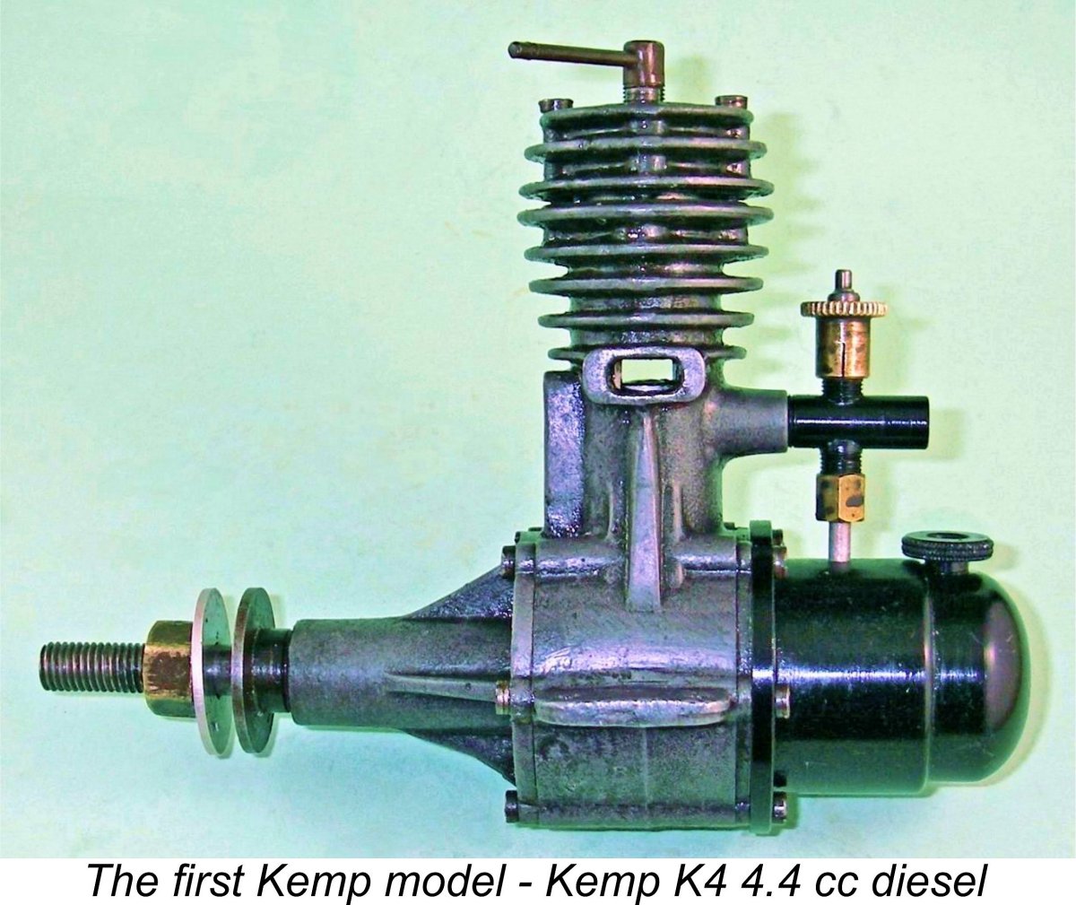 A few 8.8 cc twin cylinder diesels were also manufactured using components from the 4.4 cc single-cylinder model. These large engines were soon joined by a 1 cc crankshaft front rotary valve (FRV) diesel. This engine too is the subject of a
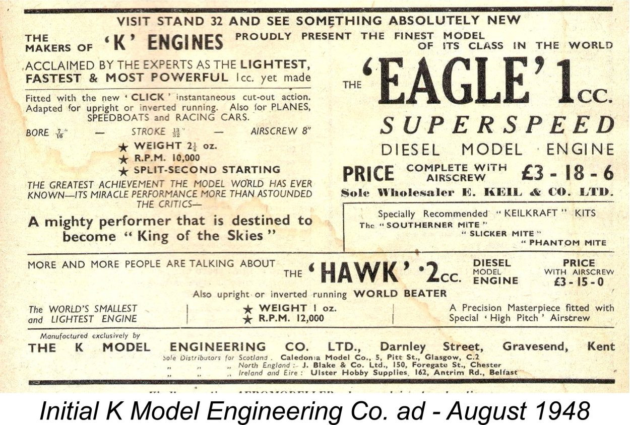
 The resulting new model was designated the 2 cc "K" Falcon, continuing the company’s “bird of prey” nomenclature. It launched the series of engines which form the main subject of the present article. The Falcon was announced in an advertisement placed by the "K" Model Engineering Co in the April 1949 issue of “Aeromodeller”. It was in essence a downsized version of the internally-strengthened
 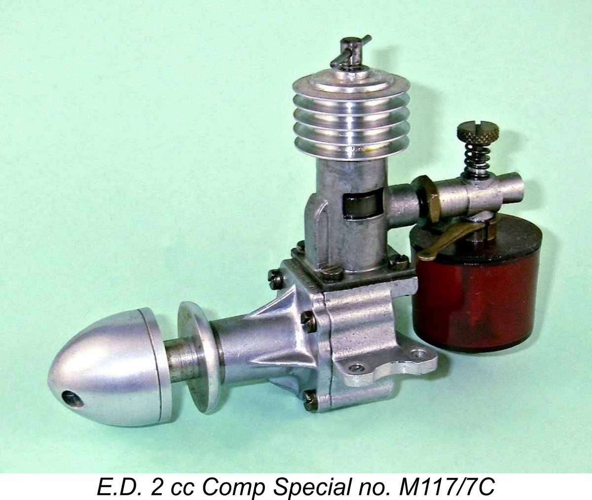 Engines of 2 cc (0.12 cuin.) displacement or thereabouts were actually quite common in Britain at around this time.
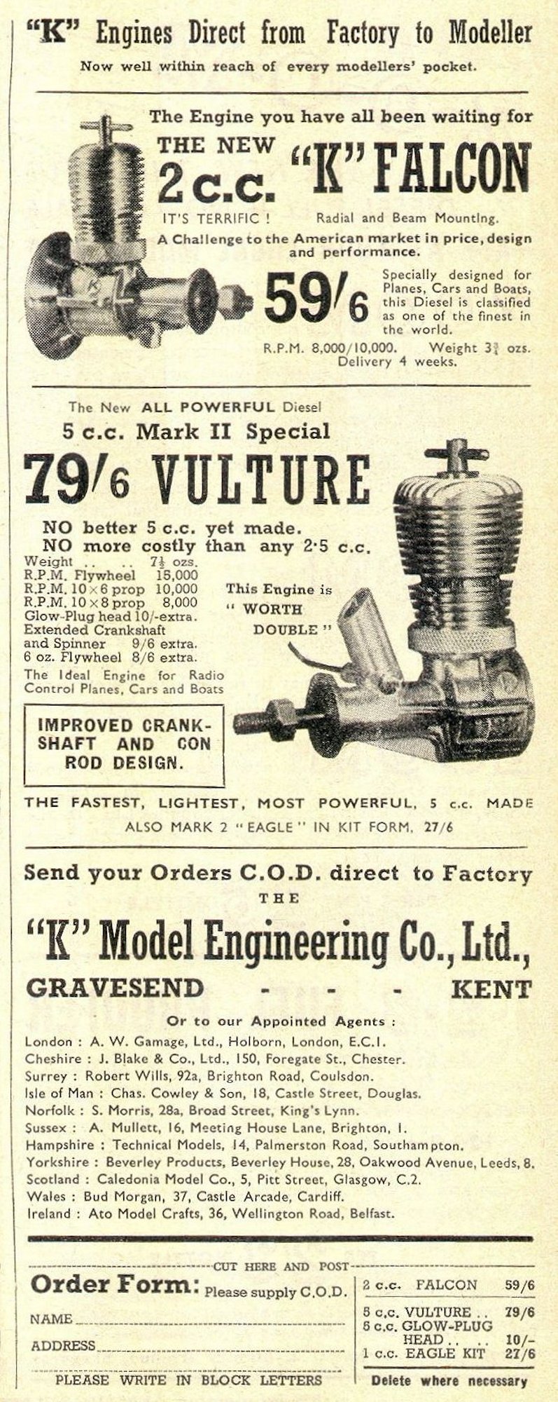
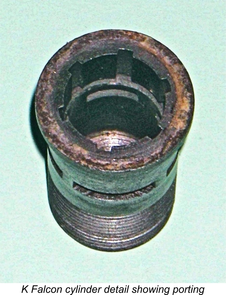 Turning now to the cylinder porting, this too possessed some distinctive features which were also carried over directly from the Vulture. The exhaust ports were essentially conventional for a radially-ported engine, consisting of a ring of four sawn ports separated by relatively thin pillars. However, the transfer arrangements were rather more unusual. The actual transfer port itself consisted of a continuous annular channel machined around the entire circumference of the inner cylinder wall just below the exhaust port ring - an example of true 360 degree porting! This annular channel was fed from the lower crankcase by six shallow and relatively narrow bypass flutes broached internally in the cylinder wall below the channel at a uniform spacing.
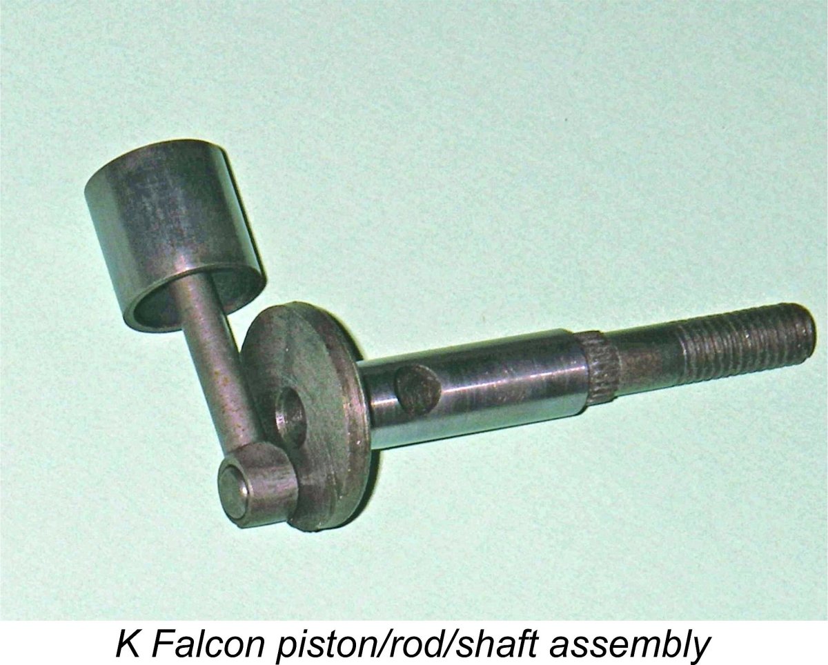
 are not noted for suffering crankshaft failures implies that this must have provided sufficient strength given the fact that the Falcon had a 60% smaller displacement than the Vulture and was moreover a long-stroke design. The crankpin had a very sensible diameter of 0.1875 in. - no shortage of strength there!
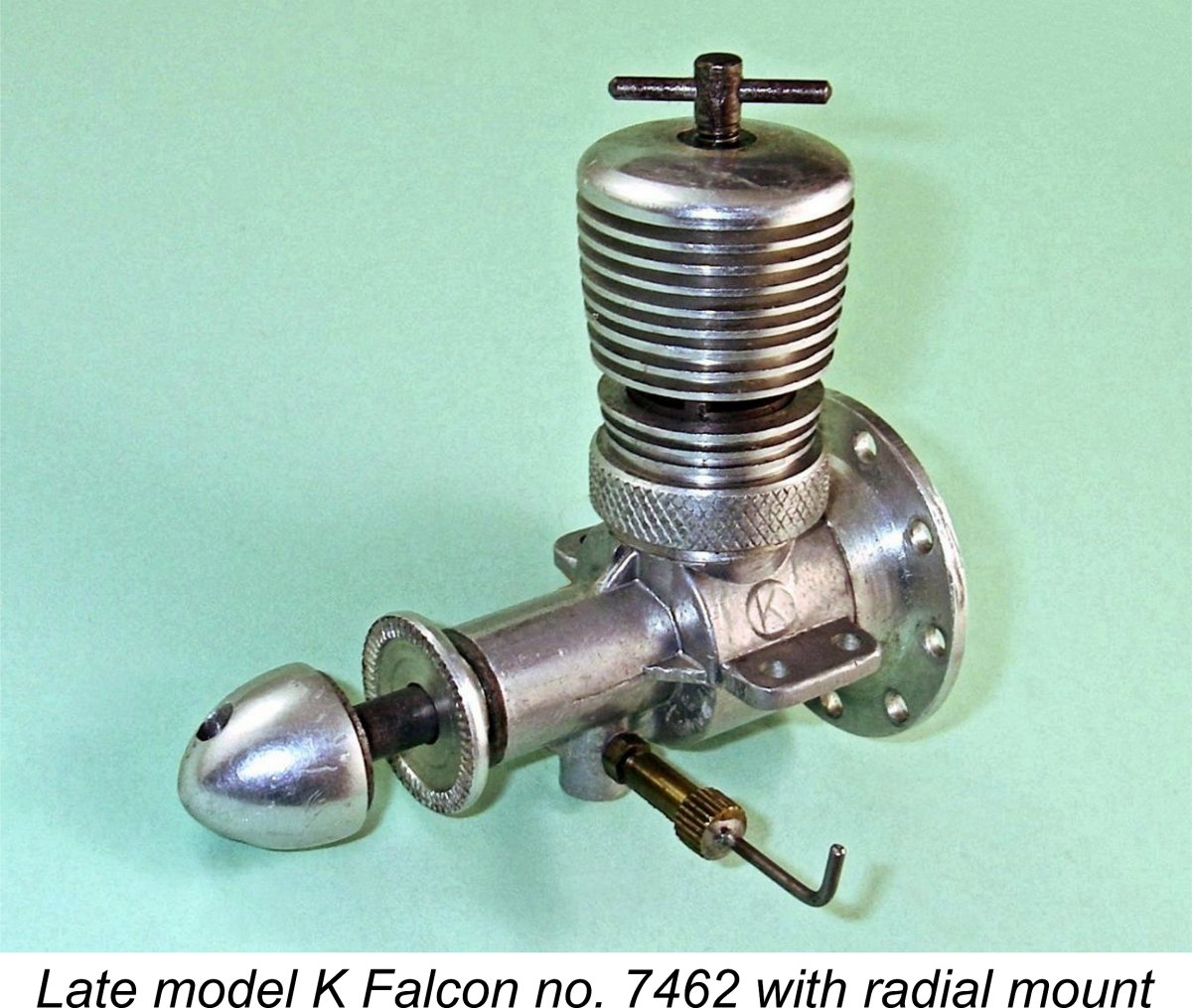 plan view and have holes drilled through them at the appropriate spacing. These act in effect as clamps to hold the lugs down on the mounting beams in the model. The result is that any shock loadings are distributed over the entire mounting lug area rather than being concentrated at the mounting hole locations as they would be if the mounting bolts acted directly on the upper lug surfaces. This approach makes breakage far less likely, also preventing the generation of witness marks on the lug surfaces.
 The engines all carried serial numbers which were stamped on the right-hand side of the case (looking forward in the direction of flight) beneath the mounting lug on that side. Apart from the serial number, the only other identification to appear on the engine was the company's well-known "K in a circle" trade-mark which was a carry-over from the Kemp Engines era. This appeared on both sides of the crankcase cast in relief above the mounting lugs.
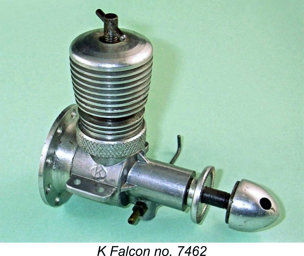 Present-day collectors who care about such things should be aware that there are a number of claimed Falcons out there which are actually conversions of the subsequent "K" Kestrel model (see below). The Falcon and Kestrel were more or less identical designs with a few largely cosmetic changes, making the conversion of one to the other perfectly straightforward if one has (or can make) the necessary parts. The giveaway is the serial number - an authentic Falcon will have a number in the 6000 plus range, whereas Kestrel serial numbers are far lower and have a K prefix. Converted Kestrel number K349 which was sold at auction some years ago was an example - it was offered as an original Falcon but is in fact either a conversion of an early Kestrel or a repair to an original Falcon using a Kestrel case. Either way, it's a hybrid.
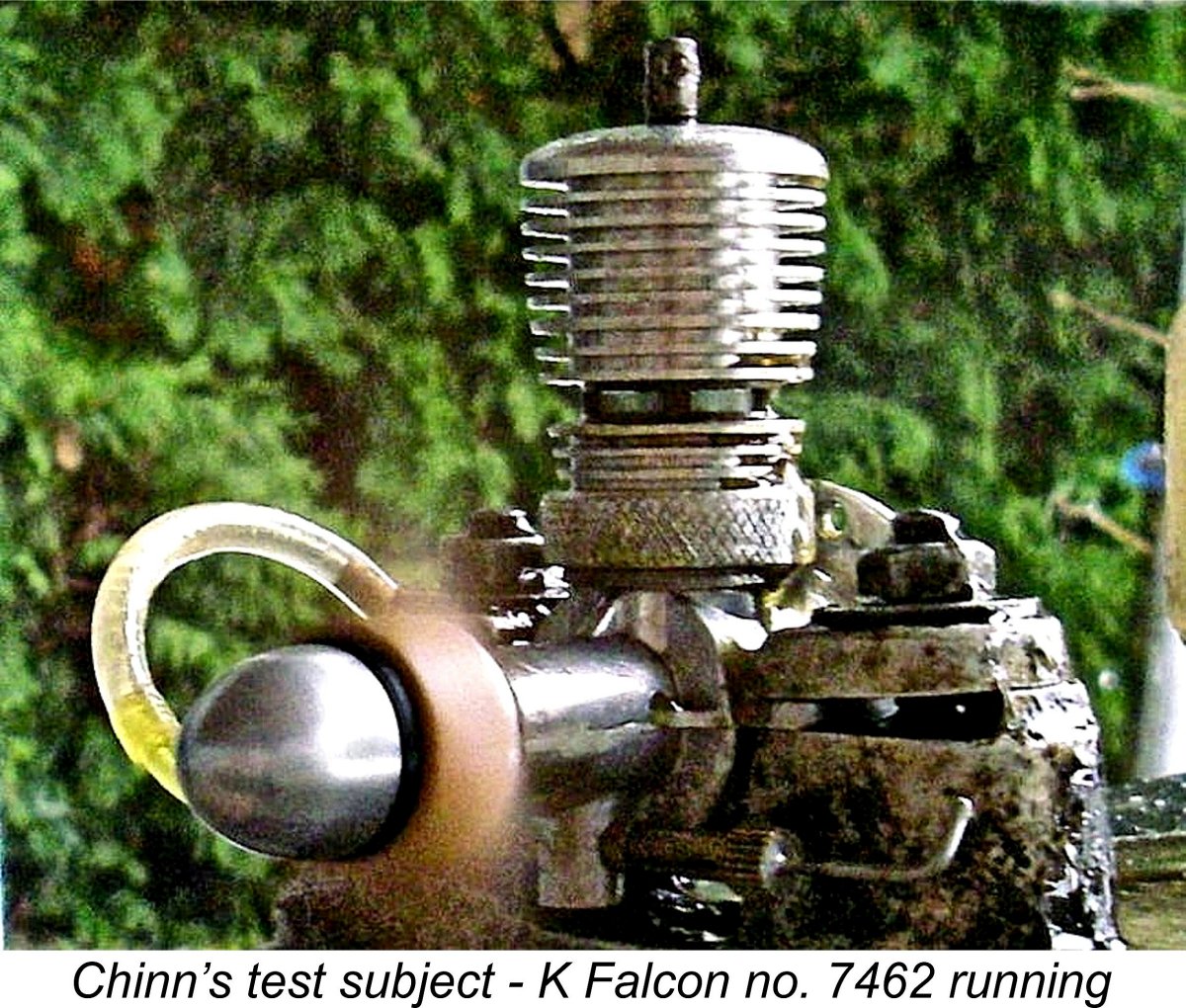 Returning to the test report, Chinn reported that the Falcon was "not quite so easy to start as some engines", a factor which may well be connected with the type of porting used. The 360 degree transfer port coupled with the radial exhaust porting meant that there was nowhere for a prime to "pool" in the cylinder when the engine was mounted in an upright configuration, as it would be during a typical test. Despite this, a prime is more or less essential for these engines when mounted in an upright position because fuel drawn from the tank by choking tends to drip straight out of the downdraft intake by gravity rather than being absorbed by the engine. Starting is actually much improved when the engine is mounted in the sidewinder configuration, as it often would be in a stunt model.
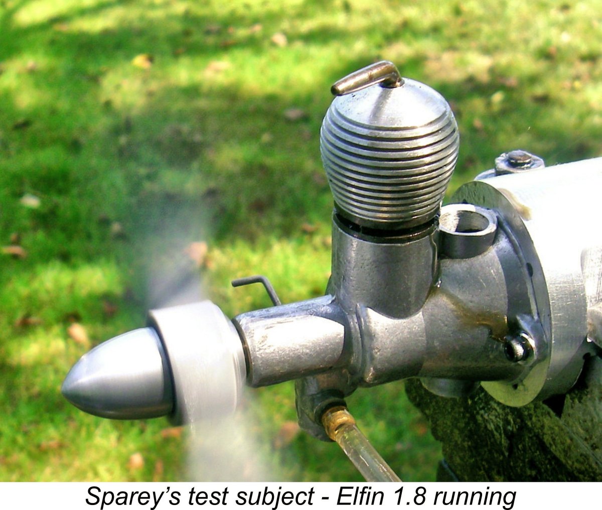
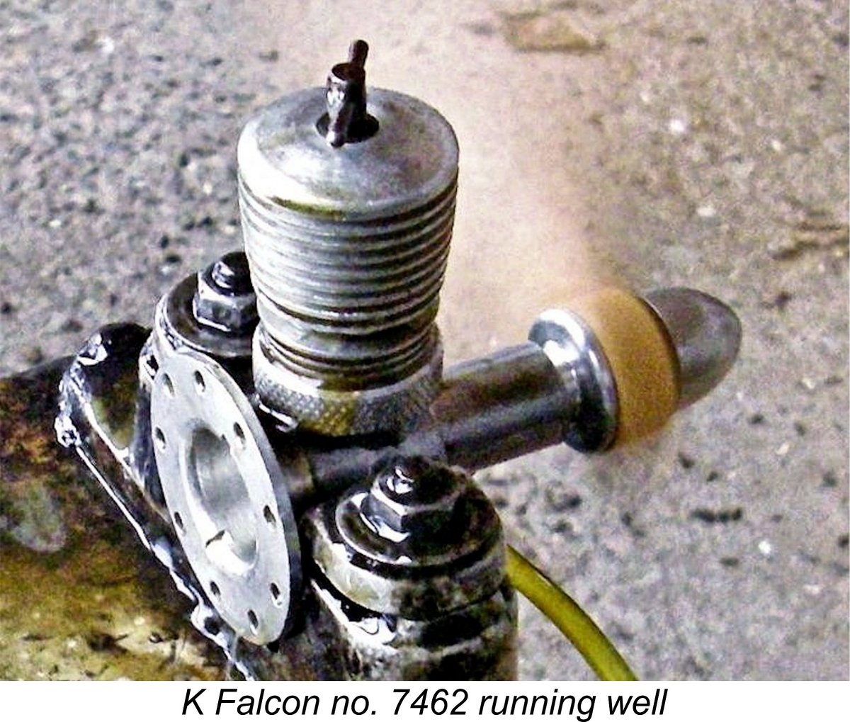 As a final note, it's interesting to observe that the Falcon peaked at only marginally greater RPM than the 8,900 RPM peak reported by Sparey in his January 1949 “Aeromodeller” test of the Mk. I Vulture. My own tests of the Vulture have pretty much confirmed Sparey's figure. The fact that the change in scale of the basically common design did not substantially affect the speed at which peak power was achieved suggests that the unique porting used on the two "K" models was a limiting factor in terms of peaking speeds.
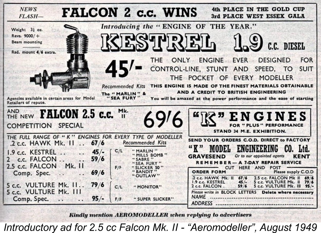
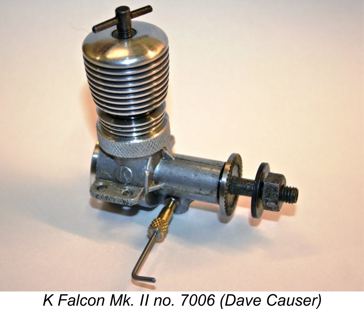
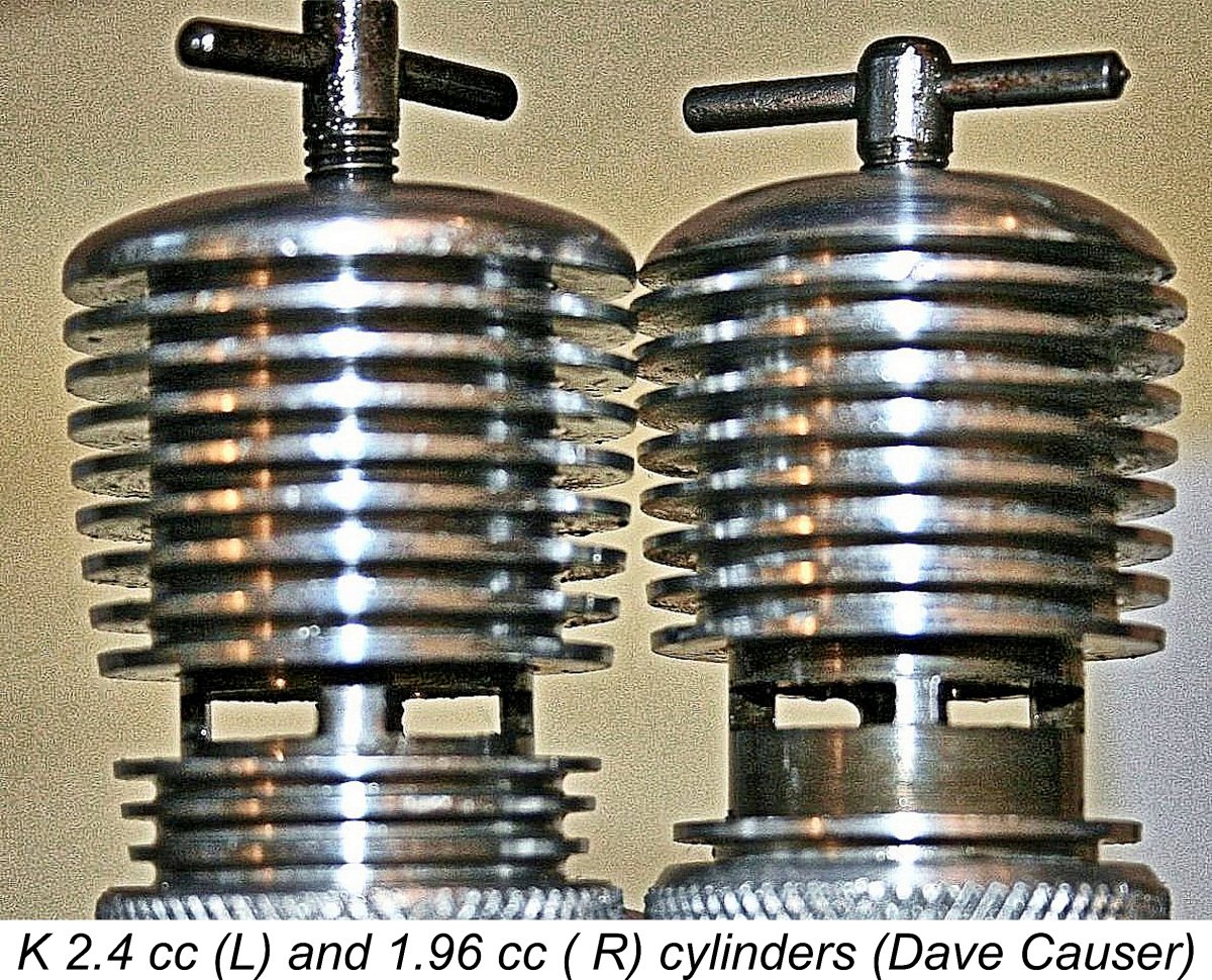
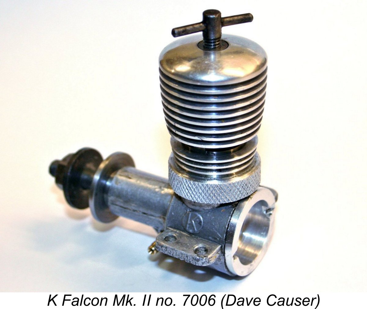
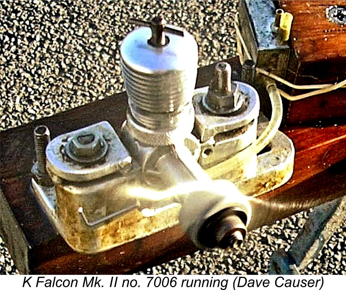
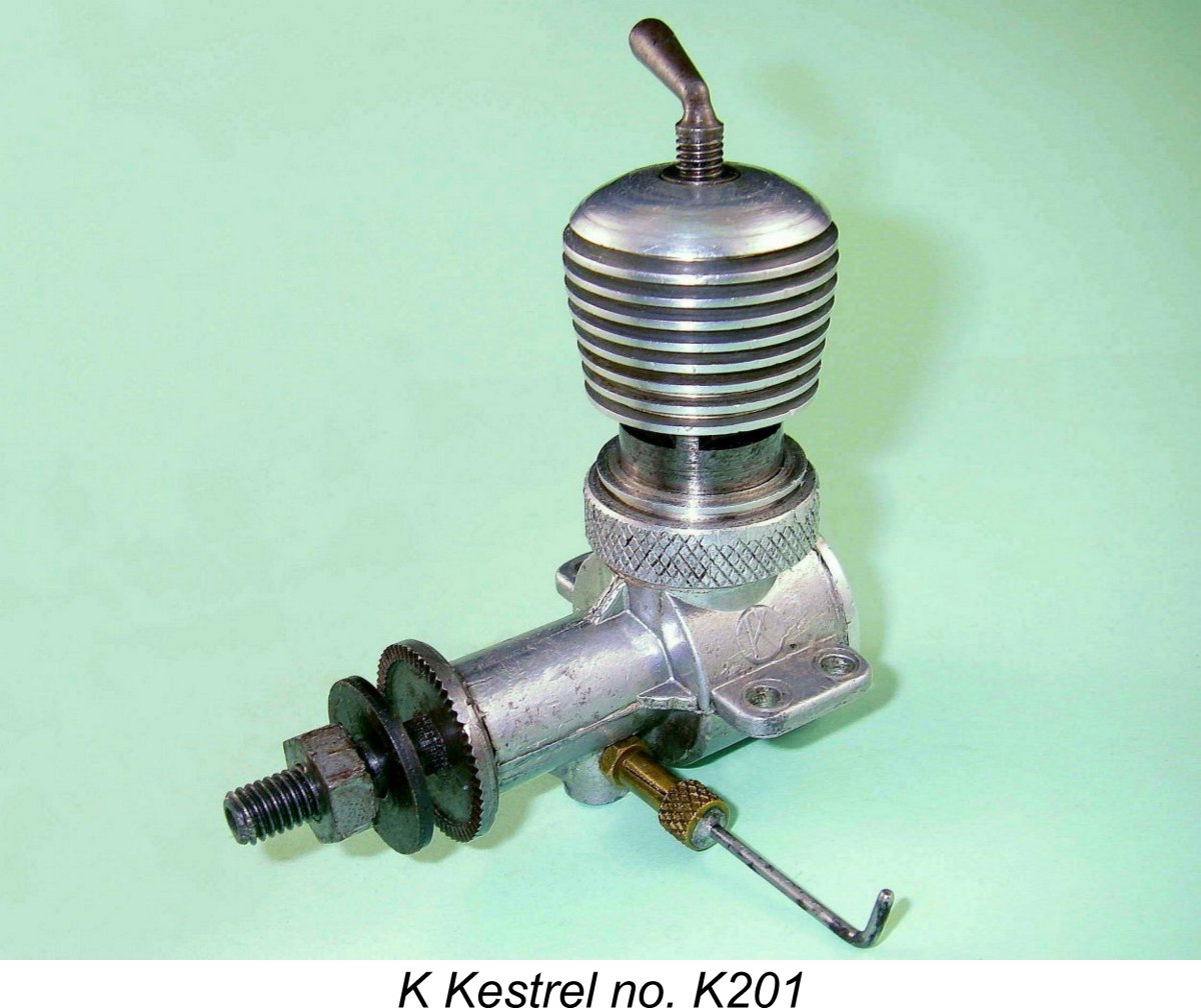 In August 1949, at the same time as the announcement of the nominally 2.5 cc Mk. II Falcon "Competition Special" discussed previously, the "K" Model Engineering Co. also introduced a second “economy-grade” variant of the 2 cc series which had been initiated in April 1949 with the Falcon. This was the well-known 1.96 cc Kestrel diesel, which was first advertised in August 1949 as "the engine of the year" along with the 2.5 cc Falcon Mk. II variant, as reproduced above.
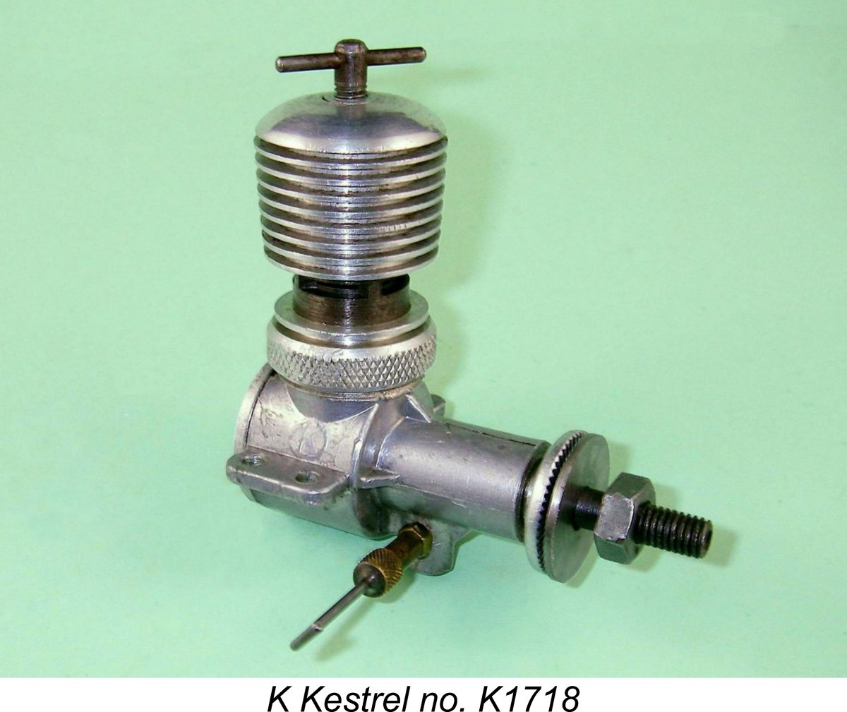 Steward seems to have reasoned that a re-named lower-cost version of the Falcon might sell well enough to generate some much-needed revenue for the company, something which the existing Falcons were not doing. It would also give the workforce something to keep them usefully occupied pending the hoped-for arrival of better times. In that regard, if it was favourably received, the new model might do much to restore consumer confidence in the K range, perhaps leading to renewed interest in the unsold Falcons and Vultures. In effect, Steward was trying yet another approach to the twin challenges of re-establishing his company's cash flow and maintaining its production capabilities through workforce retention.
 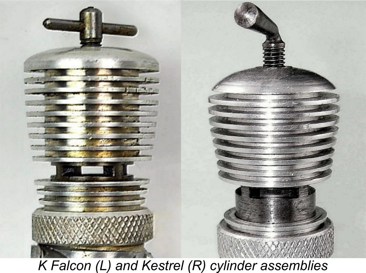 The commonly-held view of the Kestrel is that it was a somewhat less carefully-built version of the Falcon. This may be a rather simplified view of the matter, as we shall see, but it is undoubtedly correct to say that the Kestrel was to all intents and purposes the same engine with very minor cosmetic alterations. Indeed, the only immediately-apparent differences between the two models were the dog collar and the cooling jacket! The dog collar used on the Falcon had three barrel fins above the knurled ring itself, while the shorter collar used on the Kestrel had only one.
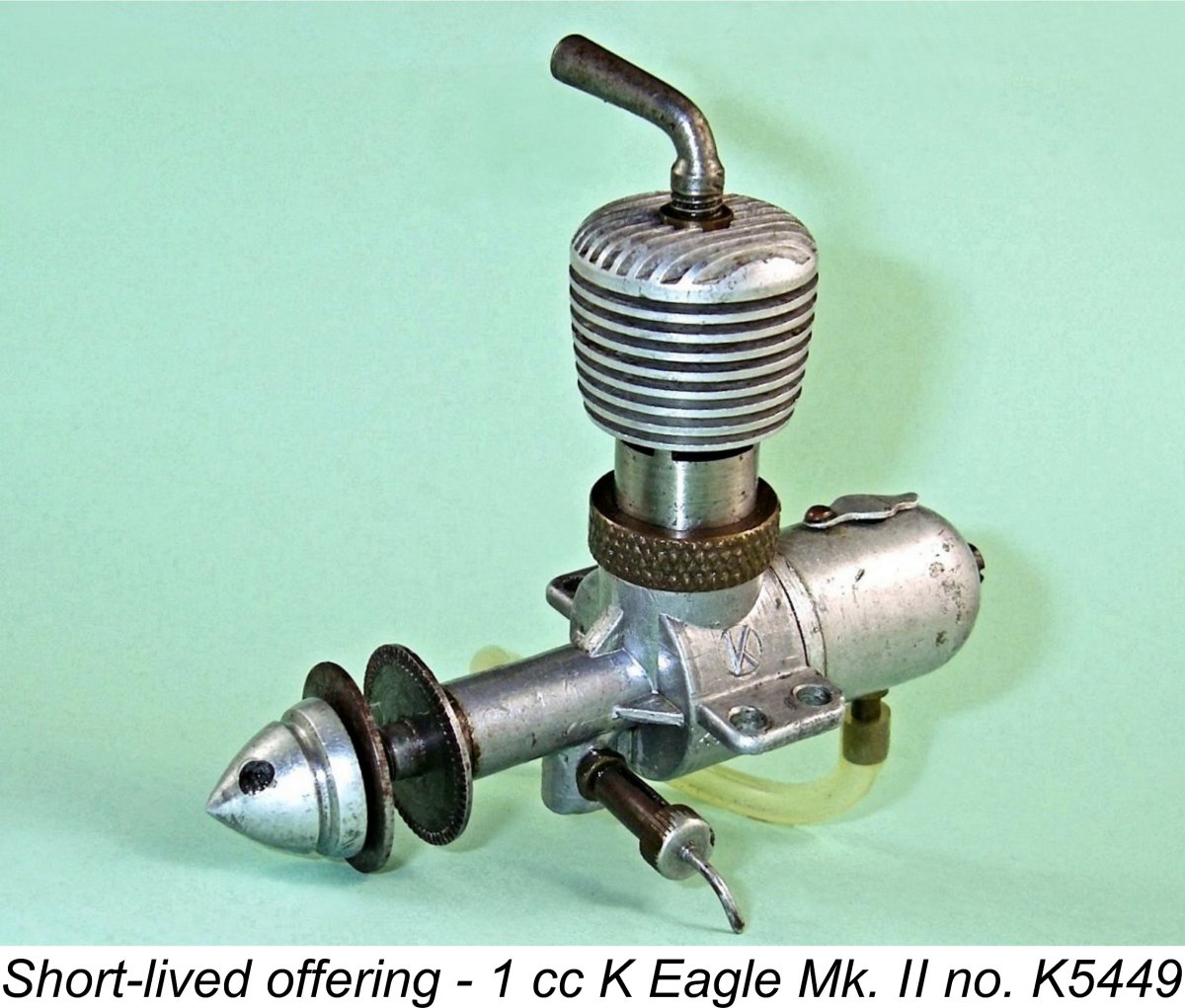
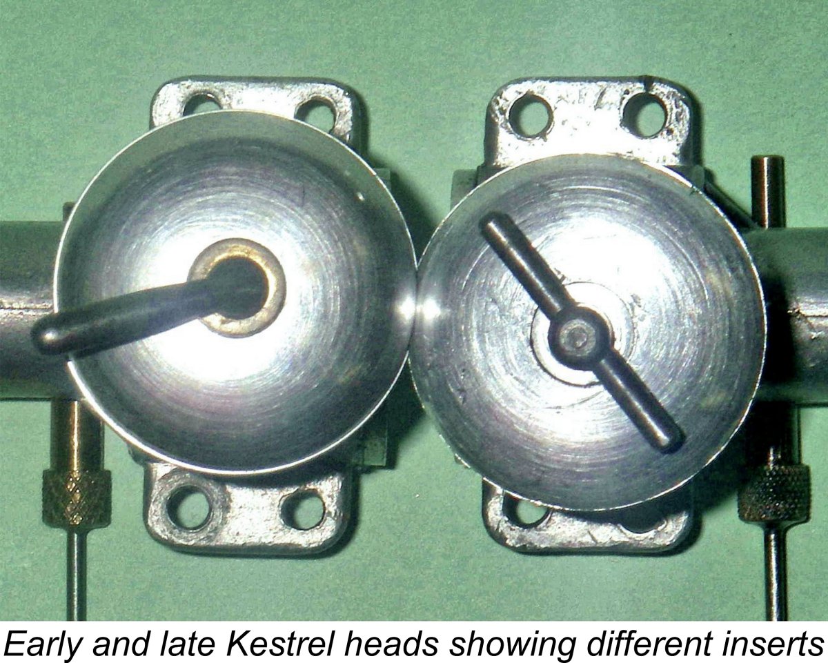 The other changes which appeared midway through the production cycle were a switch from steel to aluminium alloy for the prop driver and from brass to aluminium alloy for the head insert. A similar change to the prop driver material had previously appeared on the companion 5 cc Vulture Mk III "Competition Special". Some examples of the Kestrel were also fitted with aluminium alloy spinner nuts instead of the nut-and-washer combination more commonly encountered.
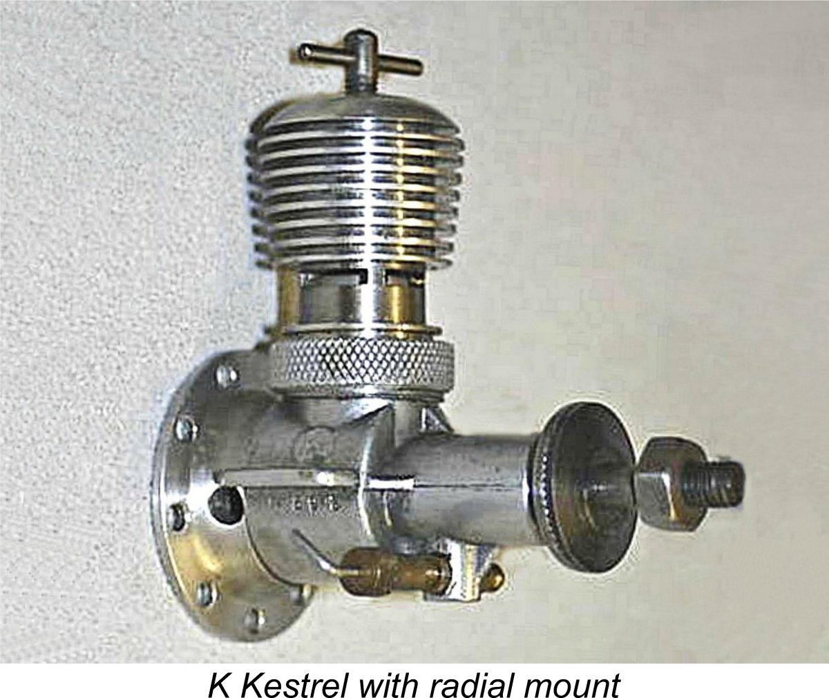 A number of owners have reported that the average Kestrel seems to be set up a little more loosely than the typical Falcon. It's presumably this factor that has led to the previously-expressed view that the Kestrel was a less carefully-built version of the Falcon. In terms of precision, there certainly seems to be some validity in this view. However, the implication that the manufacturer had lowered his quality standards is almost certainly incorrect. It’s actually far more likely that the somewhat lower standards of precision exhibited by the Kestrel were more a recognition of the realities imposed by the aging equipment used to manufacture the engines than they were of a conscious slackening in quality standards by the manufacturer.
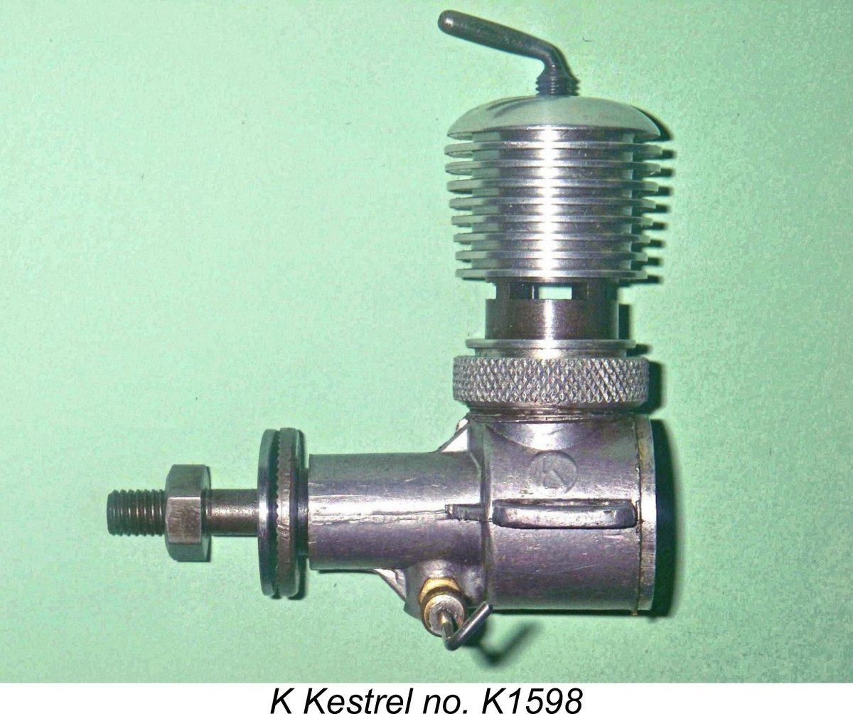
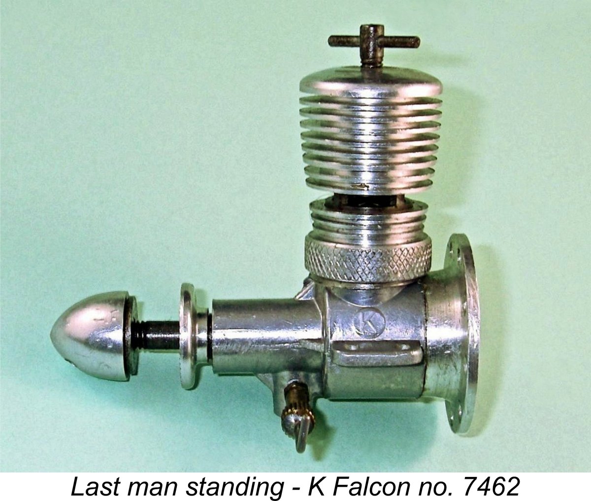 A final piece of evidence which I personally find quite persuasive in support of this scenario is the fact that the alloy head insert which was used on later versions of the Kestrel appears never to have been used on the Falcon. If the two models remained in concurrent production, one would undoubtedly expect to find later examples of the Falcon also featuring the alloy components. In fact, one would expect to find both models using the same screw-on cooling jacket. However, we don't .............
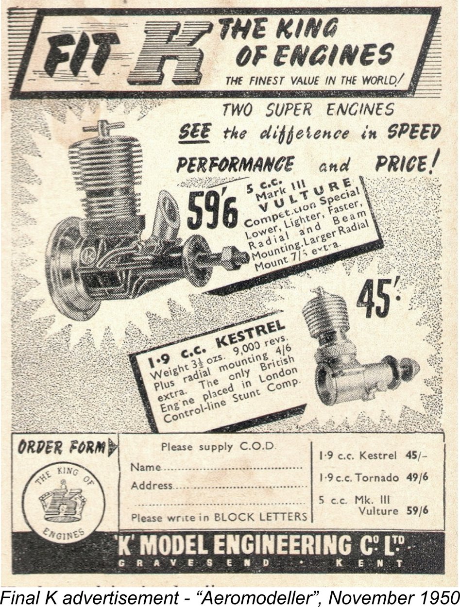
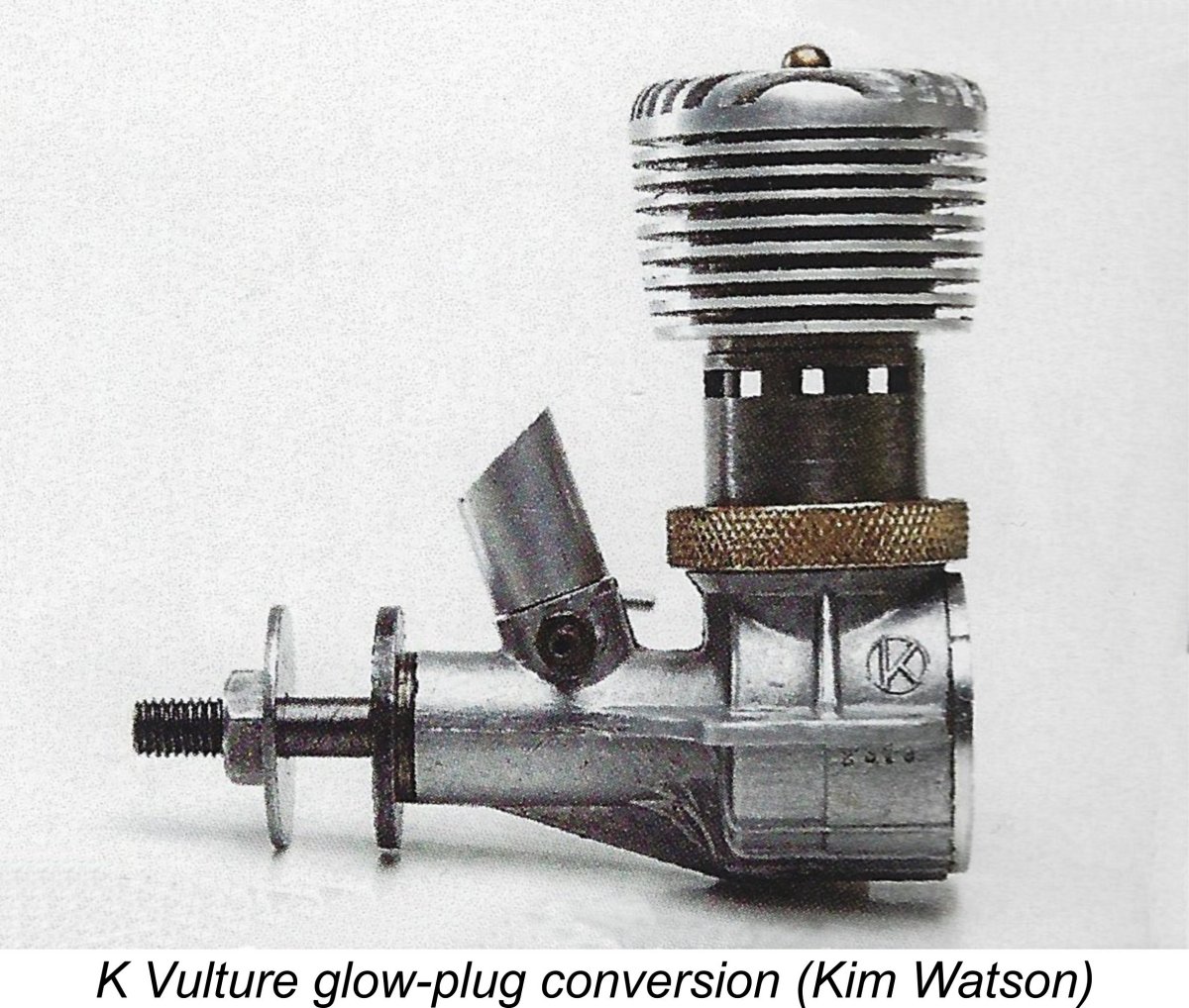 Despite these efforts, as of January 1950 the company still held sizeable stocks of several of their discontinued models, including both the 1.96 cc and 2.4 cc Falcons. These unsold units represented a significant amount of capital which was unavailable to the company and was undoubtedly depreciating as the months went by. Time perhaps for desperate measures…………….
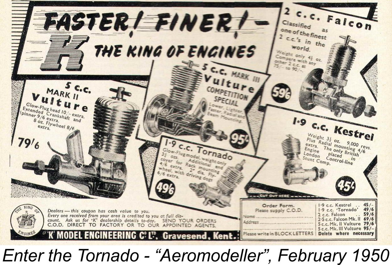 Given the company's situation at the time, it's immediately obvious why they didn't simply offer a glow-plug conversion kit for the Falcon, as they had previously done with the Vulture. The point is that they were trying to move existing inventory of unsold Falcons off the stock shelves. Offering a conversion kit for Falcons already out there would not have contributed to this objective in any way.
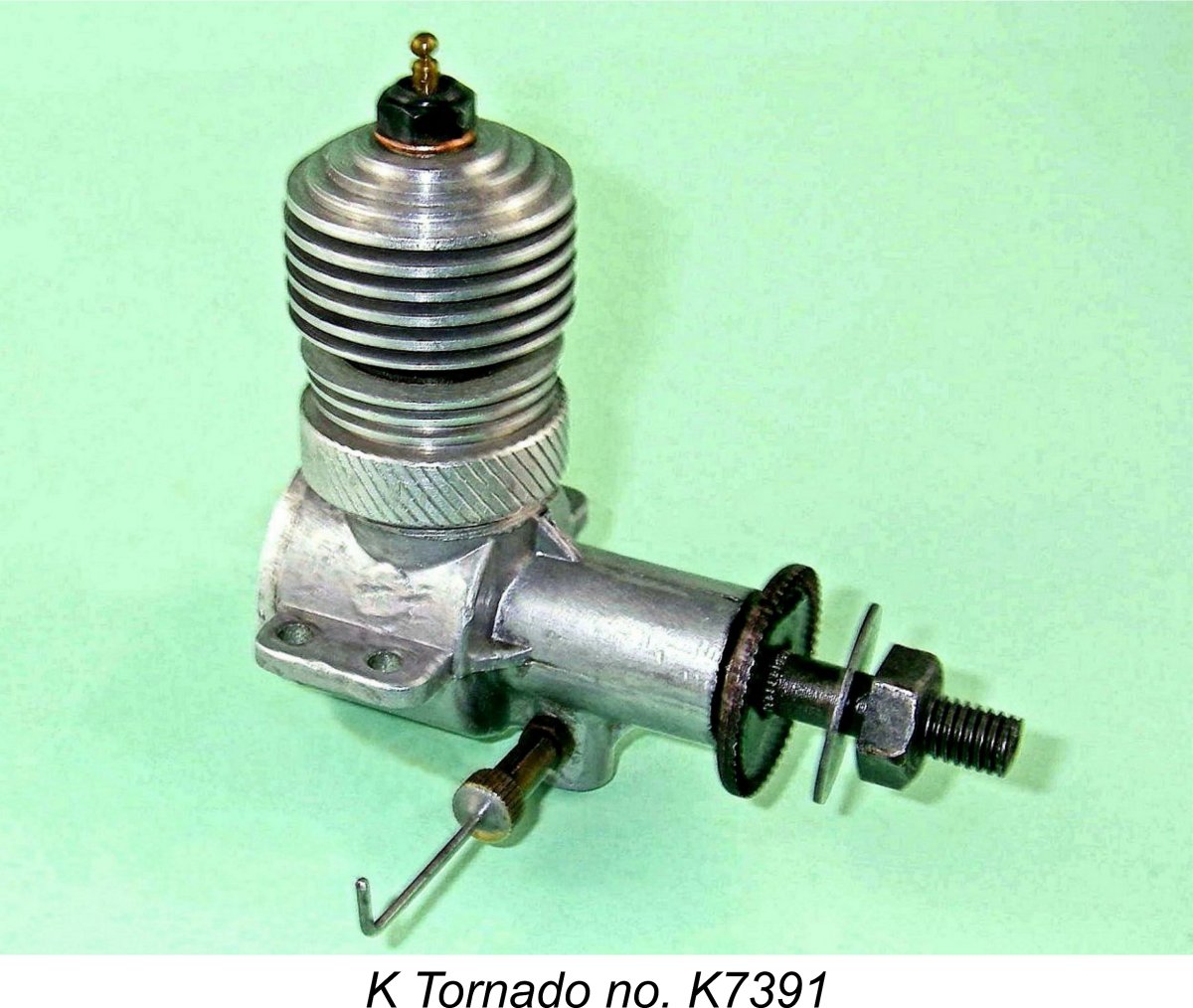
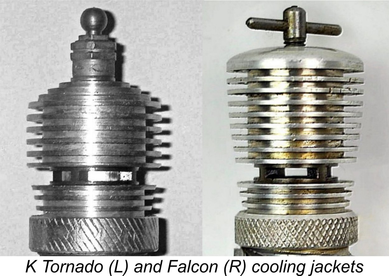 The cooling jacket used on the Tornado appears to be a standard Kestrel unit (not a Falcon component) which has simply been re-machined to reduce the external diameter of the fins, change the head contour and make the bore conform to the shorter cylinder. The latter objective was evidently accomplished by machining off the lower three fins on the Falcon cooling jacket. The former domed solid portion of the Kestrel jacket at the top had ample thickness to accommodate the progressively stepped-down portion of the Tornado's head - the Falcon jackets didn't.
 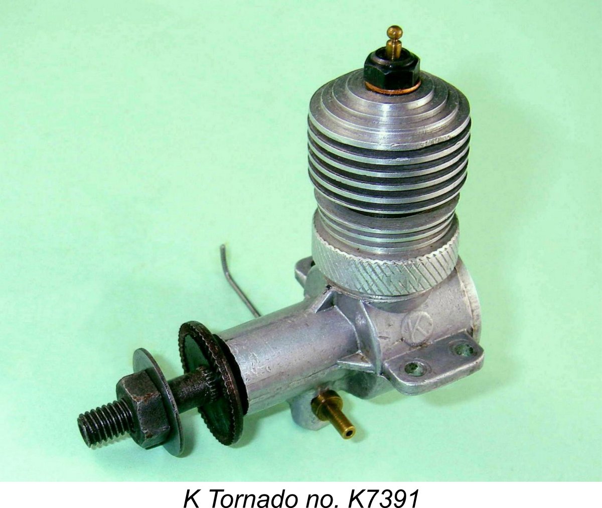 Firstly, the Tornado never received the alloy prop driver which was used on the later examples of the Kestrel. Like almost all known authentic examples of the Falcon, it retained the steel item which had been used at the commencement of production of the "K" 2 cc models. If the Tornado was in fact a new production as of February 1950, we would undoubtedly expect to find the alloy prop driver being used on all examples. There seems to be no logic whatsoever behind the notion that that the company would have reverted to the older and heavier design on a new product built from scratch.
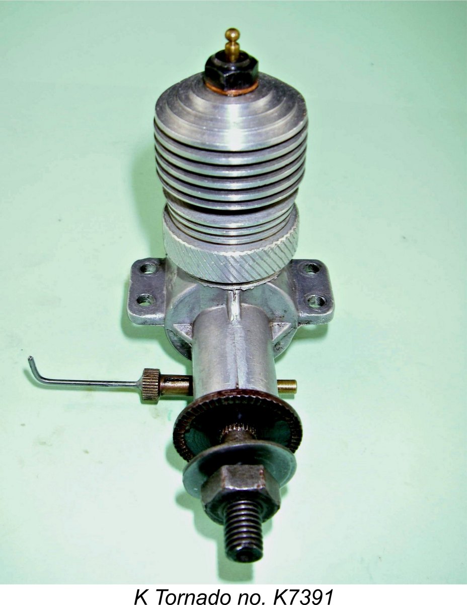 Viewed in light of these observations, it appears that the usual designation of the Tornado as "the final "K" Model Engineering Co. design to enter production" is in all probability quite misleading. In fact, all of the evidence summarized above strongly supports the notion that it wasn't a new production at all - it was simply another re-packaging of a group of existing examples of the Falcon Mk. II combined with a few residual Kestrel components. Its introduction appears to be yet another case of the company taking a few remaining examples of a discontinued model that they were having trouble selling, dressing it up in new clothes, presenting it as a new model under a new name and hoping that the buyers would appear.
 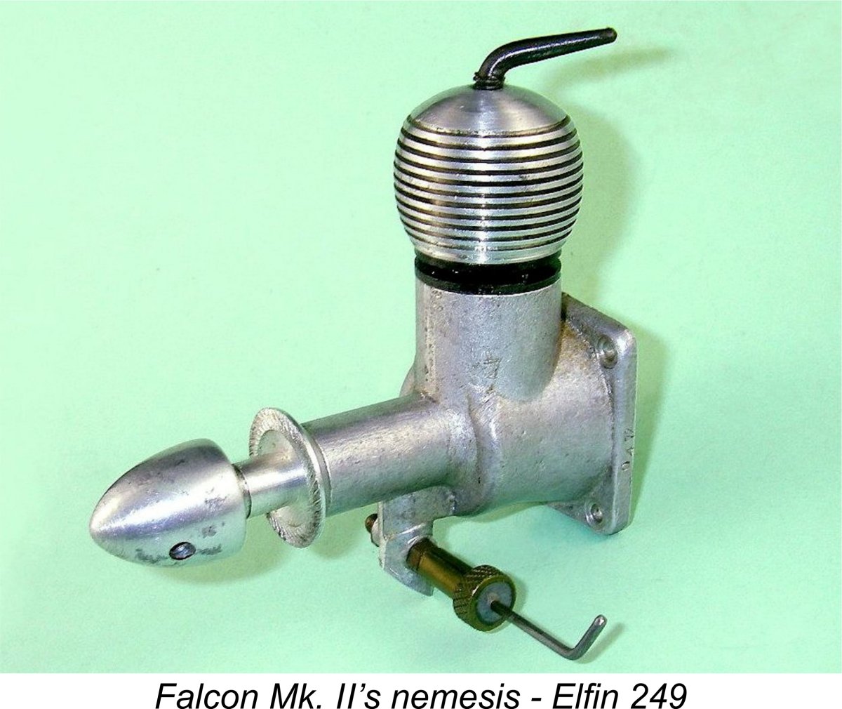 The fact that the original 1.96 cc Falcon disappeared from view at about this time creates a strong impression that by March 1950 the company had liquidated their entire remaining stock of Falcons either by selling them or by rebuilding them into Falcon Mk. II’s and Tornados in the hope that the diesel model’s larger displacement and/or the switch to glow-plug ignition might attract a few more buyers.
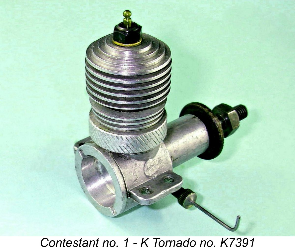 My initial round of testing took place in 2010 in support of my 2011 article on MEN. In deference to the Tornado's rather low compression ratio, I fitted the hottest long-reach plug that I could find and also elected to use an "oily" fuel having a 10% nitro content. I was well aware that nitromethane was pretty much in the unobtanium category in Britain as of 1950 and was prohibitively expensive even if one was lucky enough to find a source. Therefore, few British glow-plug users at the time would have been in a position to use anything other than a straight methanol/castor mix. However, I wanted to give the engine a fair chance, hence my decision to use a bit of nitro.
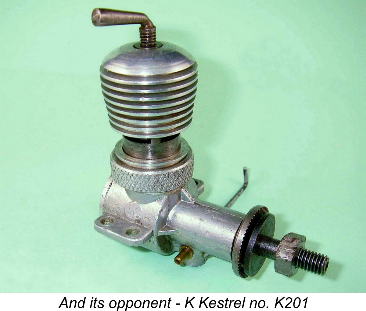 I actually tried two examples of the Kestrel during the course of my original tests back in 2010. They yielded very comparable figures, although the more "experienced" of the two (engine no. K201) tended to be 100 or so rpm up on its companion across the board. This kind of discrepancy is well within the range of variation to be expected with series-produced engines having had different levels of use. I used the results from the slightly faster engine for the purposes of this comparison as presented in my original article.

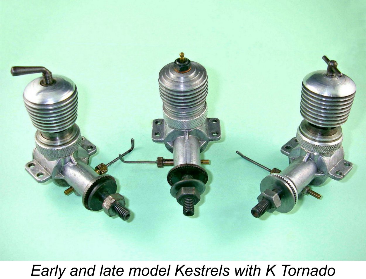 One interesting observation is the fact that both engines achieved their peak power delivery in the middle of the 9,000 - 10,000 rpm range, just as reported by Peter Chinn for the Falcon. There’s a high degree of consistency here which strongly suggests that the engine’s cylinder porting or induction arrangements may have been a limiting factor in performance terms.
 | |