
|
|
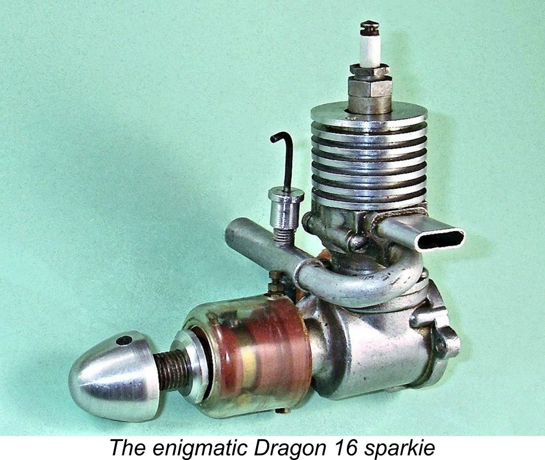
Wimbledon Wunderwerk or Wot?!? The Dragon 16 Sparkie
Some of my subjects are indeed rare, but that’s not the primary reason for their appearance in these pages - believe that or not as you wish! In fact, I see extreme rarity more as an argument against covering a given engine, because very few people will ever be able to experience such engines for themselves, making commentaries on them far less practically relevant. On the contrary, I’m mindful of the fact that the most important engines to cover are those produced in substantial numbers by the mainstream manufacturers whose products sold in the tens of thousands. This has ensured the survival of a sufficient number of examples that most model engine enthusiasts will be able to acquire one if they so desire. Hence the majoriy of the engines owned and (hopefully!) used by most of my readers will be such “common or garden” products.
I believe that at the present time of writing (2026) my coverage of the mainstream products of the British model engine manufacturing industry during the classic era is essentially complete. I’ve also covered a number of the more prominent European and Japanese ranges. However, I’ve left the story of the American industry largely in the very capable hands of my late good mate Tim Dannels, compiler of the invaluable “American Model Engine Encyclopedia” (AMEE) and former publisher of the now-discontinued "Engine Collectors' Journal" (ECJ), although I have allowed myself the luxury of a few sorties into that field. A second category which commands my attention is that select group of engines which embody some unusual or innovative technical features. This has led me to take a close look at such oddities (by today’s standards) as piston port engines, front induction sideport models, fixed compression diesels, variable compression diesels using eccentric main bearing compression adjustment and those employing moving cylinder liners. Some of these engines are undeniably rare, but that’s not the primary reason for their inclusion. My present subject, the Dragon 16 sparker from early post WW2 England, certainly qualifies under this category, as we shall see. A third factor is the general interest and/or significance of the background story behind a given range or model, especially when that story can be adequately documented. I’ve covered a number of designs having such stories to tell, encompassing a wide range of geographic origins. Engine ranges with a fascinating human interest story attached have always resonated with me - my reviews of the Yulon range, the Hill engines and the work of Ira Hassad are classic examples.
My interest in the Dragon stems from a number of factors. One, almost nothing seems to be known about its manufacturer, M. E. Bastable Ltd. of Wimbledon in South London - the obscurity of this engine and its origins is remarkable in itself. Two, it has one of the most unusual intake arrangements of my long experience as well as a unique timer design. Three, its generally-cited release date of 1948 begs the question - why was it released at all at that time………….....or was it? I hoped that undertaking some research in support of my own review of the engine might shed some light on all three issues. The fact that good examples of the engine are comparatively rare today was actually a minor factor in stimulating my interest. Fourth and finally, the Dragon 16 has a well-established reputation for being a non-runner thanks to the fact that many later examples were sold in that specifically-advertised condition. But surely they can't originally have been non-runners - why would anyone go to the trouble of making a large number of components for an engine that wouldn't run?!? For me, such a reputation has always had the effect of a red flag waving at a bull - I invariably become interested in testing the truth of such an assertion and in seeing what can be done to refute it! In the present instance, the Dragon 16 turns out to be a far better-made engine than its general reputation would suggest - its non-running reputation is evidently based upon other factors. Before getting into that aspect of its story, I’ll begin by summarizing the relatively sparse historical information that I’ve been able to dig up about the Dragon, following this up with a detailed description of a nice example in my possession. The Dragon Marque - a Survey
Every model engine publication that I’ve ever read has given the date of the Dragon’s introduction as 1948. For me, this presents a significant anomaly - given the early 1948 arrival of the commercial miniature glow-plug as well as the fact that the model diesel had been steadily coming to the fore in Britain since mid 1946, why would any British manufacturer release a new small-displacement spark ignition model in 1948 at a time when every mainstream participant in the industry had ended spark ignition production or was in the process of doing so (apart from a few notable big-bore racing models like those from Rowell and Nordec)? Even those like Yulon who chose not to become involved with diesels at the time were turning instead to glowplug ignition. It was sunset time for spark ignition - why enter that particular field at the time in question? I will confess to entertaining a gnawing suspicion amounting to a near-certainty that this is yet another classic case of an earlier commentator (probably in this case Mike Clanford) getting the date wrong and all subsequent writers simply quoting the same incorrect date without question, thus perpetuating the error. I’ve run into a number of other cases in which demonstrably incorrect information has become more or less enshrined in this manner.
The first warning bell in this case is the omission of the Dragon from the list of British spark ignition motors included in Appendix II of Ron Warring’s early 1949 book “Miniature Aero Motors” (compiled during 1948). A review of that table shows that Warring routinely included engines which were stated to be no longer in production but were presumably still to be found in use. Clearly the Dragon 16 didn’t even fall into that category as of 1948 - as far as Warring was aware, it was history. Warring was certainly aware of the Dragon marque, since he did list a Dragon 1.6 cc diesel, albeit with no dimensions or other details being included. This implies that he never had the opportunity to examine and measure one of these engines. All of this strongly suggests to me that the Dragon sparker actually appeared considerably earlier than the often-quoted 1948 date - Warring didn’t include it in his 1948 table because it was no longer around to be listed! No surprise there - even in 1947 it would have been competing with such very capable diesels of generally comparable displacement as the Mills 1.3, the Majesco “22”, the FROG 100 and the E.D. 2 cc designs in addition to the FROG 175 sparkie. By early 1948 you could add the excellent Allbon 2.8, E.D. Mk. III and FROG 180 diesels to that list. Who’d want to go up against these designs with a 1.6 cc sparker?!? To me, it seems significantly more likely that the manufacturer’s initial intention was to compete with the FROG 175 sparkie of comparable displacement from just down the road in Merton. A 1946 date would be far more compatible with such an ambition.
Already I hear someone saying that the existence of a diesel version of the Dragon is confirmed beyond argument by Mike Clanford’s inclusion of an image of such a unit in his widely-read but frequently misleading 1987 “A-Z” book, along with a statement that this engine ran well. However, Clanford’s book is notorious for including engines associated with a given manufacturer which were actually created after the fact by un-named others (see below for another relevant example). Hence it cannot be assumed that the illustrated unit is a Bastable original - indeed, both the apparent incorporation of a fully machined upper cylinder jacket (as opposed to a casting) and the seeming use of hexagonal socket head bolts for both the head fasteners and the comp screw strongly suggest that it is of far more recent origin.
Returning to the dating issue, I suspect that the source of the 1948 date generally assigned to the Dragon 16 sparker was nothing more authoritative than the unsubstantiated assertion of that date in Mike Clanford’s previously-cited 1987 book. While his book is certainly a very useful and entertaining pictorial reference, Clanford seems to have done very little if any original research on his subjects. Consequently, the book has proved to be woefully off base in assigning such details as dates and origins to a number of engines whose stories I’ve recounted elsewhere. It cannot be viewed as an authoritative source. The most egregious dating errors that have come to my attention so far were Clanford’s assignment of a 1948 date to the 1953 Super Tigre G.24 10 cc racing engine and his citation of a 1955 date for the mid-1960's Katipo engines fron New Zealand! There are many other examples…………the 1947 date assigned to the 1948 Airstar 2.15 cc diesel is another. To summarize the dating issue, the existence of a diesel version of the Dragon in 1948 would make perfect sense in the context of the times, even if it never got past the prototype stage. By contrast, the continuing existence of a spark ignition version at that time makes no sense at all. Given all of the above considerations, I must admit that I’m inclined to believe that a far more probable release date for the Dragon 16 sparkie was mid to late 1946. The engine is highly unlikely to have survived into 1948 in spark ignition form. OK, I’ve said it - now prove me wrong!!
The fact that home assembly was often involved might be expected to lead to quite wide variations in quality between surviving examples - different purchasers would bring different levels of care and skill to the assembly of the motor. My good friend Peter Scott recalled having had one of these engines which was characterised by a plenitude of leaks and a “rubbish” points assembly! He never saw an example actually running at any time. In terms of media or advertising coverage, a search by my good mate Maris Dislers came up empty in terms of any mentions of the Dragon 16 in the British modelling media at any time during the 1940’s. The engine appears to have been one of that period’s best-kept secrets! Where Clanford got his 1948 date is anyone’s guess - perhaps it was nothing more than Clanford’s own guess! A poorly-reasoned one if so………… My good mate Gordon Beeby of Australia has uncovered what appears to be the sole appearances of the Dragon in the contemporary advertising record. These took the form of advertising placements by A. E. Peters of West Wickham in Kent, who touted themselves as "Kent's Model Shop". These advertisements appeared in the series of Ian Allan publications which constituted their "Model Aviation" series. The initial placement in "Model Planes Annual" (pub. January 1949) referred to the engine as the "Dragon 1.6" without specifying whether it was a sparkie or a diesel. In the three subsequent placements, the name "Dragon" appeared at the end of the list of engines said to be in stock, no other details being provided. The final mention of the Dragon came in "Model Aviation 1950", which was published in February 1950. It seems highly unlikely that the Dragon sparker would still be on offer at this date, leading to the suspicion that this may have been the near-mythical diesel version. Either that, or it represents a last-ditch attempt by Bastable to dispose of unsold stocks of the engines.
Clanford arranged for a number of these parts to be assembled into complete engines. An individual whom he approached in this context early on was Miles Patience's late father Mike Patience, who received a number of components for assembly. Mike P. quickly discovered that this wasn't just a case of assembling the engines - some machining work was required. Mike quickly decided that he didn't think much of the Dragon in any case, consequently losing interest and withdrawing from the project. However, he retained a small collection of components for possible future use.
Thankfully, my valued mate Eric Offen was kind enough to provide me with the accompanying scan of the manufacturer's assembly instruction leaflet. This did much to clarify the gasket issue. It seems that gaskets were never produced for this engine - instead, the owner was advised to use some form of jointing compound when assembling the engine. Given the number of joints involved in sealing the crankcase, the design clearly requires that these joints be effectively made gas-tight if the engine is going to be operated. However, if it isn’t going to run anyway, why bother with gaskets or any other form of sealant? I for one am very grateful that whoever assembled my example refrained from using any form of jointing compound, since the use of such materials greatly compromises the subsequent tearing-down and reassembly of an engine. The use of gaskets is greatly preferable. I have a feeling that this issue may provide a means of identification of "original" examples of the Dragon 16. If it's assembled with well-aged jointing compound in accordance with the manufacturer's instructions, it's perhaps more likely than not to be an example assembled back in the day from one of the original "kits". If on the other hand it has no provisions at all for crankcase sealing, it's highly likely to be one of Mike Clanford's latter-day re-creations. These instructions also clarify the nature of the "kits" which were supplied for these engines by the original manufacturers. For obvious reasons, the text is silent with respect to components which came already assembled as supplied. One can deduce from this that the cylinder liner came already installed in the upper cylinder casting, with the bore completely finished and the head already installed. The piston was already lapped into the bore and was fitted with its gudgeon pin and conrod. The crankshaft was already installed in the main bearing, complete with the combined prop mounting/cam component already secured in place. Finally, the timer came fully assembled, merely requiring fitting to the main bearing housing. Completion of the engine merely required the combination of these completed assemblies - a very simple task.
This was confirmed by the appearance of a Maple Models advertisement in the same issue. The engines were said to be assembled from new parts, but were explicitly categorized as being “for collectors only”. It’s almost certain that the vast majority of the “as new” Dragon 16's that still show up today are examples of these units. The example owned by Peter Scott was almost certainly one of these engines, as is my own example in all probability. Buyer beware - they may or may not be runners!!
This creation was featured in Peter Chinn’s “Latest Engine News” column in the September 1982 issue of “Aeromodeller”. Mike Thomas provided the following description of this project: “In partnership with Arthur Polson of Winnipeg, the last remaining spares of the English vintage “Dragon 16” were rounded up. I cast a new intake manifold to connect the two original pipes, and a new centre bearing journal for the new double-throw centre shaft which connects the original crankshafts, front and back. The timer (contact breaker) was modified to a double point system and placed at the rear, the front shoulder being covered by a tapered sleeve”.
Mike Clanford included an illustration of this creation alongside the original Dragon 16 single-cylinder model and the related diesel, characteristically failing to mention its origin. This unfortunately gave rise to an impression that the twin was an experimental model from the original manufacturer rather than being the far later completely distinct creation that it actually was. It’s a not-infrequent failing (among many others!) of Clanford’s book that he regularly illustrated such “engines that never were” without clarifying their origins at the hands of constructors other than the original manufacturers - his “Mamiya 29 sparker” is another example into which I’ve Incidentally, Mike Thomas’s success with the PT Dragon 32 twin makes him a prime suspect for having also created the previously-mentioned Dragon diesel illustrated by Clanford. He certainly had the parts available, while such a conversion was well within his demonstrated capabilities. If I’m to be completely honest here, I have to say that I’m in two minds about the creation of engines like this Dragon Twin. On the one hand, the design and construction of such a unit requires a level of skill and dedication which can only command our respect. On the other hand, the use of original components from a relatively rare classic to create an engine which never existed appears to me to represent a squandering of a great opportunity. I’d actually far rather have seen these components used to make good running examples of the original single-cylinder model than used up creating examples of an “engine that never was”. The use of replica components for such a project would be perfectly acceptable - the use of original components appears to me to be highly questionable, flying very much in the face of normal conservation ethics. The Dragon's next media appearance came in the form of an article by John Goodall which appeared in the March 1999 issue of John's "Model Engine World" (MEW) magazine. This article added no historical information whatsoever, confining itself to a physical description of the engine. Nonetheless, it did make some useful points. Unfortunately, John reiterated Clanford's 1948 date without stopping to think about the implications discussed earlier. He also failed to question the absence of gaskets despite the fact that these were clearly necessary if the engine was to run. To me, it appears almost certain that this was one of the "non-runners" assembled by Clanford. John actually recognised this possibility in his article. Regardless, that’s about all that can be said regarding the history of the Dragon 16 unless some kind reader is able to supply additional information. Let’s proceed to an examination of an actual example of the engine. The Dragon 16 - Description
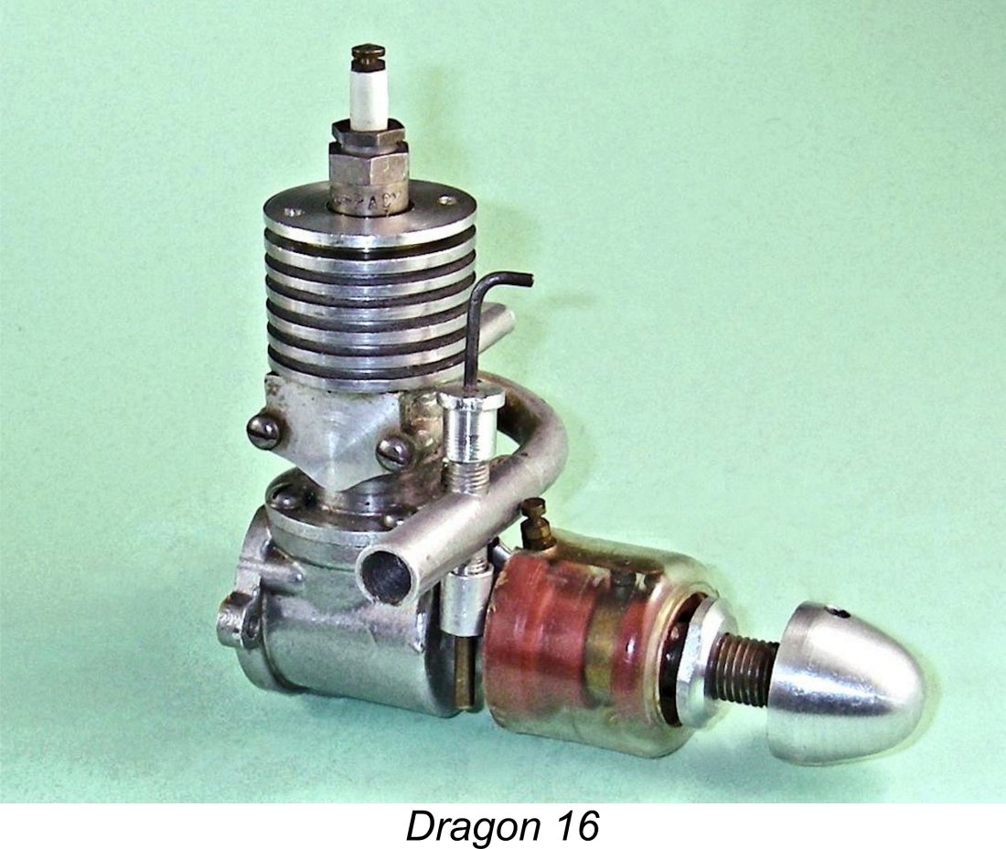
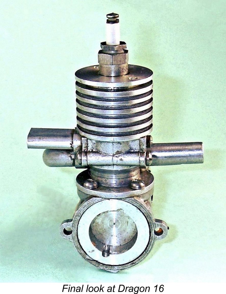
One’s first impression of the Dragon 16 is that it is very far from being another of the relatively crude small-scale “garden shed” productions which were not uncommon at the time. The machining is cleanly and competently carried out, while the gravity die-castings are of more than acceptable quality. Fits throughout are excellent. The engine is notably compact, with a quite pleasing appearance - the accompanying comparative image alongside a 1.5 cc M.E. Snipe diesel should help to give some impression of its size. The following description will be greatly clarified through repeated reference to the attached image of a collection of Dragon 16 components provided by Peter Scott as well as the earlier image of Mike Patience's assemblage. Most of the components to be described here are clearly visible in those images.
This made it almost certain that it was one of the units assembled in the early 1970's at the instigation of Mike Clanford and sold by Steve Blake as non-runners. It was clear that if I was going to actually get it running, I would have to tear it down and rebuild it with gaskets in place. My first step was to remove the plug. When I did so, the head unscrewed with the plug still in it - whoever had assembled this example had omitted to tighten the head properly, clearly not expecting the engine to be run! While this was unplanned, it did have the benefit of allowing me to take accurate direct measurements of the engine’s bore and stroke. These turned out to be nominally ½ an inch apiece (0.500 in./12.70 mm) for a calculated displacement of 0.0982 cuin. (1.609 cc). The engine weighs in at 121 gm (4.27 ounces) complete with Pacy spark plug as illustrated but without either a tank or an ignition support system.
In terms of its basic functional design, the Dragon 16 is pretty much a conventional sideport spark ignition unit of the mid 1940’s. However, it does present several rather unusual features upon first acquaintance. The most obvious of these is the design of the intake. The cylinder induction port is located on the left-hand side of the engine (looking forward in the direction of flight) directly beneath the exhaust. Mixture is supplied through a long intake tube The rationale behind this design seems pretty clear - the intention was evidently to create an engine having an unusually short overall length for a sideport design. It also places the intake in a very convenient location for finger-choking. However, these benefits are achieved at the cost of an unusually long and convoluted intake tube. An issue which may not be immediately apparent is the fact that this routing of the induction tube brings the needle valve control arm into close proximity to the spark plug. I can see it being relatively easy to inadvertently touch the plug's central electrode while making mixture adjustments. If this occurred while the engine was running, the results would be quite shocking! Another issue which I could see becoming problematic was the fact that the induction tube was merely a press-fit in the installation flange. With repeated use involving needle valve adjustments, this would almost certainly become loose over time. I attempted to improve my own example by applying some Loctite to the joint.
A relatively early origin is implied by the use of a bypass passage which is open to the atmosphere, being sealed with a flat alloy plate retained by two 6BA machine screws. The bypass is supplied at its lower end through a "race track" piston skirt port and a matching aperture through the cylinder liner. This 1930’s style of bypass had largely gone out of favour by the The cylinder head is a screw-in component which is provided with two diametrically opposite holes to permit the use of a pin spanner for tightening. It is centrally tapped for a standard ¼-32 plug. Compression ratio is a volumetrically measured 5 to 1 - a woefully low figure. The available range is of course severely compromised by the fact that with a screw-in head the final alignment of the component when tightened down cannot be guaranteed. This forces the use of a completely flat underside for the head with no provision for accommodation of the piston baffle at top dead centre and no pretence at an efficient combustion chamber.
The conrod is a nicely machined component of typical British “dog bone” pattern made from aluminium alloy. The bearings at both ends are bronze-bushed and completely free from detectable play. The bushings at both ends are pressed in and are of adequate length - another quality touch. The crankshaft is a composite item made up from three separate components - main journal, heavily counterbalanced crankweb and crankpin - which were brazed together, presumably in a jig. This assembly looks rather undernourished, even for a 1.6 cc sparker. Presumably the fact that the engine was a relatively small low-compression sideport sparkie would keep operating stresses down to levels which such a shaft assembly could absorb.
I’ve saved the best for last! The other really unusual feature of the engine is the timer design. The timer components are assembled on a cleanly-moulded base formed from some kind of hard non-metallic red material. As received, the timer base on my example was frozen solid to the main bearing housing, making adjustments to the ignition timing impossible. I had to resort to quite drastic measures to get it unstuck. With plenty of penetrating oil around the joint areas at front and back, I first applied compressive pressure using a drill chuck in the lathe tailstock (relying on the compressibility of the timer base material) and then used a carefully-installed gear puller to apply forward pressure. This treatment did the trick – the compression phase shifted things microscopically just sufficiently to allow the penetrating oil to wick into the joint. Then using the puller, the timer came off with no damage. It turned out that the timer body had been “glued” to the housing by corrosion, which I gather from others is a not uncommon condition with these engines. I cleaned things up, rendering the timer readily adjustable while still being sufficiently stiff to hold a setting. It would seem that the resistance of the timer to unwanted auto-rotation during operation was intended to be adjusted through variations in the tension of the brass collar on which the fixed point is mounted. This would "squeeze" the timer base material against the underlying main bearing housing.
The timer is encased in a clear plastic shroud which is a firm push fit onto the front and rear outer diameters of the red timer base. Internal clearances are tight - if pushed in all the way, the front of the shroud can actually interfere wth the opening of the points. It's essential to check the timer function after installing this shroud. Of course, the engine would run perfectly well without the shroud. There's no timing adjustment arm - I suspect that the intended means of adjustment of the timer during operation was to rotate it with the fingers using the shroud for purchase. The idea was evidently that the non-metallic timer housing would be a fairly firm push fit onto the main bearing housing, hence retaining its setting during operation, but could still be rotated as necessary by gripping the shroud and turning it. The shroud would protect the points from disturbance during such adjustments. The moving point is attached to a thin bronze leaf spring which appears to me to be The dwell period (points closed) is of the order of 65 degrees - a generous allowance for an engine of this type, making adequate allowance for possible point "float". For more information on this parameter and its implications, see my separate article on spark ignition engine operation. The arrangement for the provision of a cam to actuate the timer is also unique in my experience. The front of the notably skinny crankshaft protrudes a considerable distance beyond the front of the bronze-bushed main bearing. It is left completely plain, with no cam being formed in its surface or any provision being made for attaching an airscrew. Both of those roles are filled by a separate externally threaded steel sleeve which fits over the exposed length of the crankshaft and is secured by a steel stake, which is visible in the image at the right. The rear of this sleeve incorporates the cam, while the balance of the component is externally threaded to accommodate both an unusual screw-on prop driver and a nicely-formed alloy spinner nut. The prop driver is provided with flats to enable it to be held securely while the prop is being tightened - a thoughtful touch. However, the prop driver is completely plain, with no knurling whatsoever to grip the prop. I would expect prop slippage to be pretty endemic. The external thread on the sleeve is a somewhat unusual 5/16x26 BSB - don't lose that spinner nut!! The potential weakness of this arrangement should be obvious - the security of both the cam and the airscrew is completely dependent upon the single stake which retains the front sleeve in position on the shaft. I would be checking the integrity of that stake frequently, and I would not stand in front of this engine while running at any time! The rather unorthodox character of the front end components just described is a bit of a puzzle, because the rest of the engine is actually quite competently designed and manufactured. It’s clear that the elusive Mr. Bastable put a considerable amount of effort and thought into the design and construction of this engine. All key fits and finishes are first rate. This being the case, why was such an seemingly inadequate front end assembly adopted?!? Beats me …………. The Dragon 16 on Test In preparation for an actual test of the Dragon 16, it was of course necessary to get my example into running condition. The freeing-up of the timer was only the first step - next on the list was the plugging of the numerous bottom end leaks. To accomplish this, it was of course necessary to tear the engine down most of the way. I elected not to disturb the prop mounting set-up, hence not removing the shaft, but everything else came off. One design issue that was highlighted by this process was the extremely awkward location of the cylinder hold-down screws. It was impossible to get a straight shot at them with a screwdriver - a set of hex-head or socket-head fasteners would be far better. I managed all right with great care, but the slots in the screw heads will almost certainly become marred by more than one or two dismantling operations. Make the first one count! I made gaskets for all the joints and reassembled the engine. Success! The engine now "popped" in a healthy manner when turned over without a plug fitted. So it was now in running condition from a purely mechanical standpoint. However, my troubles weren't over! It turned out that the needle valve was non-functional - in fact, I'd classify it as a dummy! The spraybar was not drilled though to the throat at the required 0.063 in. clearance diameter and the 1/16 in. dia. needle itself terminated at the top of the spraybar with a blunt end - it had merely been fitted to make the engine appear to be operational! The aluminium alloy thimble was seized solid on its threaded spigot. I managed to get it off and clean up both the thimble thread and the female thread on the spigot to restore function. I then drilled out the spraybar to the throat and made a new needle with a tapered end. After this treatment, the thimble would screw in and out just fine. I installed the needle in its thimble with a bit of Loctite to help it to hold its relative position in the thimble. The jet is a separate brass insert which is retained by an internally threaded thimble of its own. It was in perfect condition for functionality. An air pressure test confirmed that I now had a working needle valve assembly. Having freed up the timer, cured the bottom-end leaks and returned the needle valve to fully-functional condition, I found myself with an engine which gave every indication that it should run just fine, albeit at a relatively modest level of performance. My ingrained curiosity forced me to the resolution that I would have to put this impression to the test! However, in view of the seemingly dodgy crankshaft structure and prop mounting/cam assembly, I decided in advance that I would keep the amount of running time down to a minimum. I just wanted to determine whether or not prove the engine would run! If it did so, I also wanted to gain some feel for its handling and running characteristics. Given the engine's use of two-point radial mounting, I had to begin by drilling and tapping two appropriately-spaced holes in one of my radial mounting fittings made from a length of extruded aluminium alloy T-section material. I also decided that I didn't want to spend time fighting with a constantly-slipping prop. Accordingly, I drilled and tapped a knurled PAW prop driver to the required 5/16-26 BSB thread, which I reckoned should sort this problem. My final preparatory step was to make up a short wire having clips at each end to connect the fixed point to the engine structure, thus grounding it. The engine would not run unless this step was taken. Since I didn't have access to the manufacturer's instruction sheet, the selection of an appropriate test airscrew posed a bit of a dilemma. I wasn't expecting this engine to deliver much in the way of perfomance (assuming that it ran at all!), while at the same time I didn't want to subject the crankshaft and prop mounting arrangements to any significant levels of stress. After some thought, I eventually decided to try the Dragon with a Top Flite 8x4 wood prop, which should impose low levels of torque. If the engine managed 7,000 rpm on this load, it would be developing around 0.040 BHP - in the general range of my realistic expectations. I used my standard sparkie test brew of 75% Coleman Camp Fuel (white gas) and 25% SAE 60 mineral oil (AeroShell 120). The sparks were supplied by one of my Larry Davidson solid state triggering systems, which have proved extremely dependable in service. Full details of these systems may be found in my separate article on spark ignition engine operation. In view of the awkward needle valve replacement as well as the dubious structural integrity of the joint between the induction tube and its installation flange, I elected to set the needle part-way open and use a remote needle valve in the fuel line for running adjustments. This is a very useful approach to testing in cases where needle valve function may be questionable for any reason. I also elected to test the engine with the plastic timer shroud removed, just in case attention was required to the points during the test. So far, it's all good, right? Well, now comes the negative part! The Dragon started firing immediately, but simply would not generate a sufficiently powerful firing burst to allow it to pick up on the fuel line. The best that I could get was an unenthusiastic half-second firing burst, after which the thing just died. I got the impression that the very low compression ratio wasn't helping. I checked the fuel line, finding that flow to the jet was unobstructed. The engine simply didn't have the required combination of adequate suction and initial firing energy to allow it to draw on the fuel line and keep going. I suspect that a replacement needle valve assembly might help, although the problem of the very marginal firing burst would have been unaffected by this. However, if I changed the needle valve assembly, it wouldn't be a Dragon 16 any more, would it?!? This being the case, I decided to abandon my efforts and put this one down as a non-runner, exactly as advertised! Conclusion
OK, so it didn't run. However, in other respects the Dragon 16 actually exceeded my expectations going in. Rather to my surprise, it turned out to be a comparatively well-made engine, especially where it counts. One may argue with the design of the timer and prop mounting arrangements as well as the rather skimpy crankshaft configuration, but the general quality of the engine’s construction compares quite favourably with that of other commercial products of the period. The very low compression ratio, inefficient combustion chamber configuration and convoluted induction arrangements would discourage anything special in the way of performance, but the engine was a perfectly acceptable product nonetheless in terms of its general quality of construction. The complete absence of any contemporary commentary or advertising coverage makes it appear quite likely that the Dragon 16 project died before it really got started. It’s clear that a considerable inventory of finished components was created, but it seems probable that very few kits were sold or complete engines assembled before the project was abandoned. In all likelihood, what killed the Dragon 16 in its cradle was the competition from the likes of International Model Aircraft (IMA) with their FROG 175 sparkie and the emerging threat from the diesels such as the Mills 1.3 which began to appear on the British market in mid 1946. Given a choice between the Dragon 16 and the Mills, there would be no contest. Bastable may have recognised this and decided to cut his losses, perhaps after experimenting with a diesel conversion. A pity, because he clearly had the ability to develop and manufacture a good product. So there you have it - all that I’ve been able to learn about one of the British model engine manufacturing industry’s forgotten failures. The Dragon 16 is an interesting unit in many ways and a fascinating collector’s item. Just be aware that if you take the plunge on one of these, you’re probably getting a non-runner, exactly as advertised! ____________________________ Article © Adrian C. Duncan, Coquitlam, British Columbia, Canada First published April 2023
|
 My motivations for choosing the subjects of the articles which appear on this website are highly variable. I should start right off by stating for the record that the rarity of a given engine is not among the major criteria upon which my selections are based.
 And then there are the others …………… the engines which attract my attention purely because they represent a mystery of some kind. I’ve always loved mysteries! Such questions as where and when they were made, who made them and even why they were made frequently lack authoritative answers. Once again, the subject of the present article, the Dragon 16 spark ignition model, falls squarely into this category. In such cases, my very sincere hope is that the publication of an article, however incomplete due to gaps in my own knowledge, may stimulate the sharing of additional information from others who know more than I do.
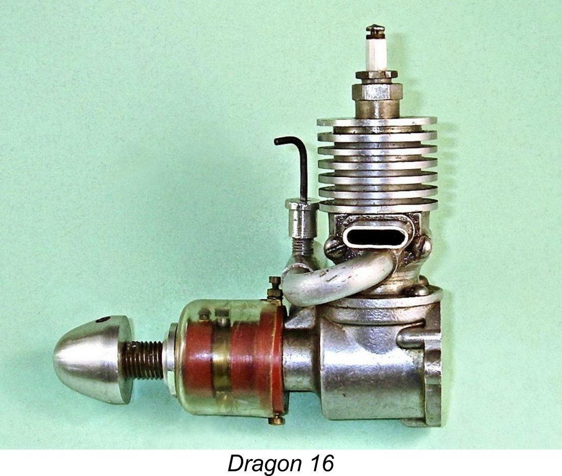 The Dragon 16 was a compact 1.6 cc (0.098 cuin.) sideport spark ignition powerplant which was manufactured by M. E. Bastable Ltd. of Merton Road, Wimbledon, London S.W.19. This location is only a little to the north-east of the contemporary
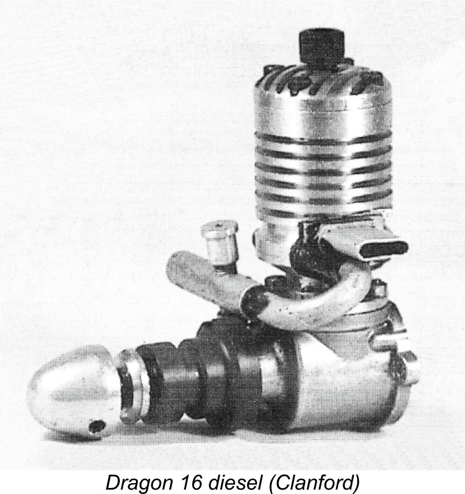 By contrast, Warring’s inclusion of a Dragon 1.6 cc diesel in his 1948 listing, even if only by name, is far more intrinsically credible - the dating certainly fits. I suspect that such an engine must have existed, otherwise it’s hard to see why Warring would have mentioned it, even in passing. At the very least, he must have heard of such a model from a source which he considered to be authoritative.
 That said, a diesel version of the Dragon 16 sparkie would have had to look something like this - there are relatively few options available. The only differences that I would have expected to see would be the incorporation of the contra-piston into a screw-in head, thus allowing the use of the standard upper cylinder casting and liner, as well as a conventional tommy bar comp screw. The piston baffle would also have to be machined off. Of course, such a conversion would have been greatly simplified by the use of fixed compression.
 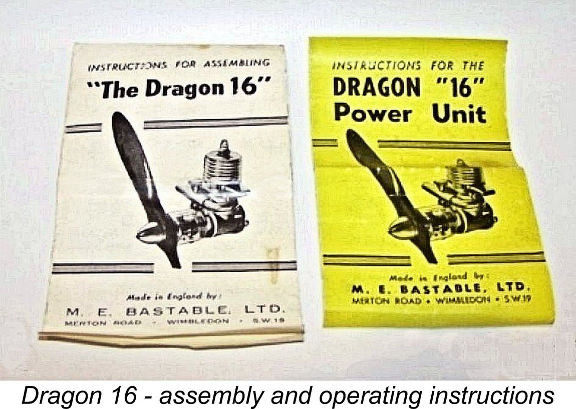 Whatever the date of its introduction, it’s evident that the vast majority (or even perhaps all) of these units were supplied in component form for assembly by the purchaser. A set of printed assembly instructions was supplied with these “kits”. There was also a well-presented operating instruction manual. The existence of these documents proves in itself that a serious attempt to market this engine was in contemplation.
 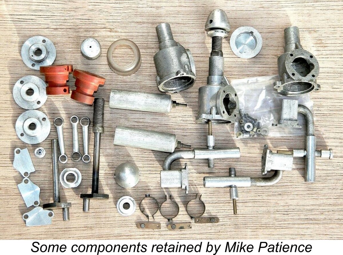 However, the Dragon did actually enjoy a few moments in the media spotlight many years later! During the early 1970's, Mike Clanford somehow came into possession of a sizeable assemblage of original components for the Dragon 16, reportedly from someone associated with its original production. The fact that such a large stash of unused components still existed in the early 1970’s represents pretty good confirmation that the engine had attracted little sales attention - its components had clearly been significantly over-produced. It’s extremely fortunate that someone took the trouble to preserve those components rather than throw them into the scrap bin.
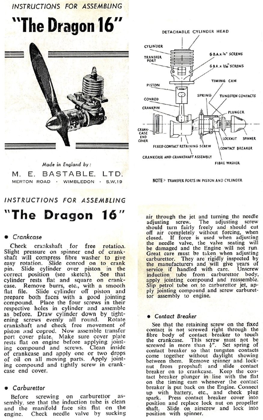 Mike Clanford then passed the project on to someone else to finish the assembly work. It's apparent that the examples for
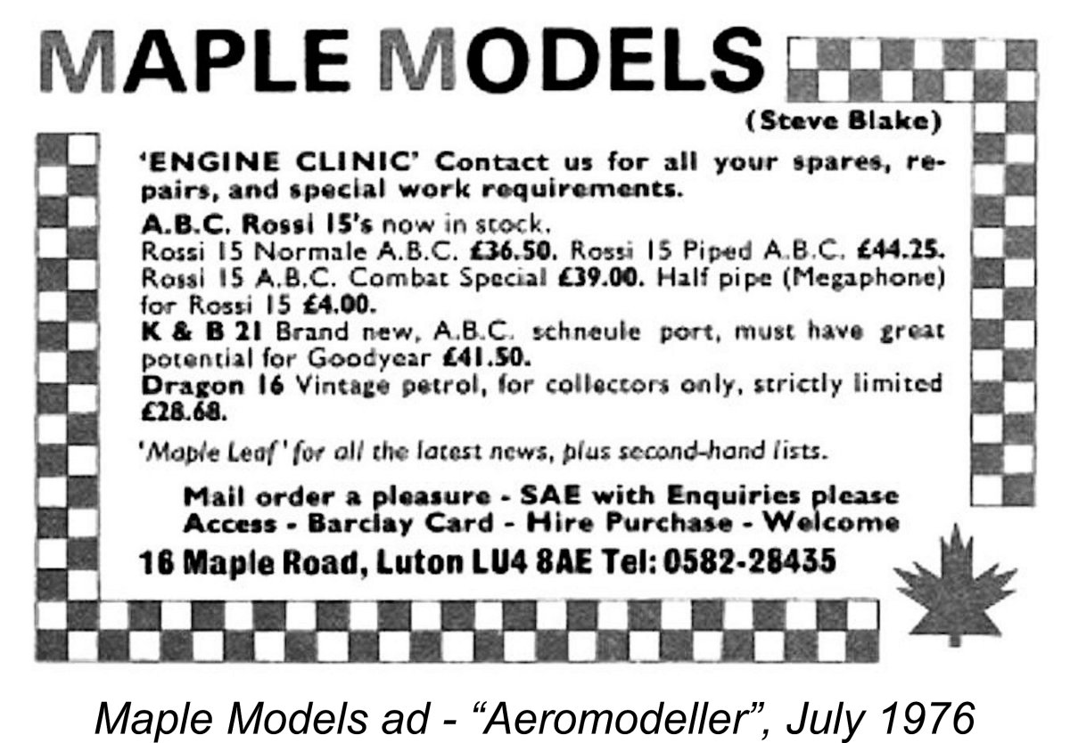
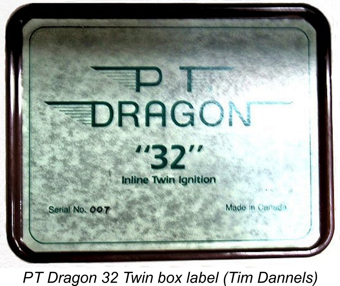
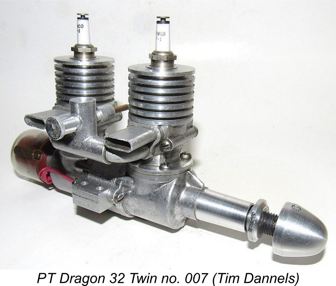 It appears that this effort didn’t last long. By around 1980-81, the residue of the Dragon 16 project had been acquired by the late prominent Canadian collector Arthur Polson, then of Winnipeg, Manitoba but later resident in Vancouver, British Columbia, where I knew him well. Arthur persuaded the late talented model engine restorer and constructor Mike Thomas of Toronto to undertake the construction of a short series of twin-cylinder 3.2 cc units, each being based on a pair of Dragon 16 engines.
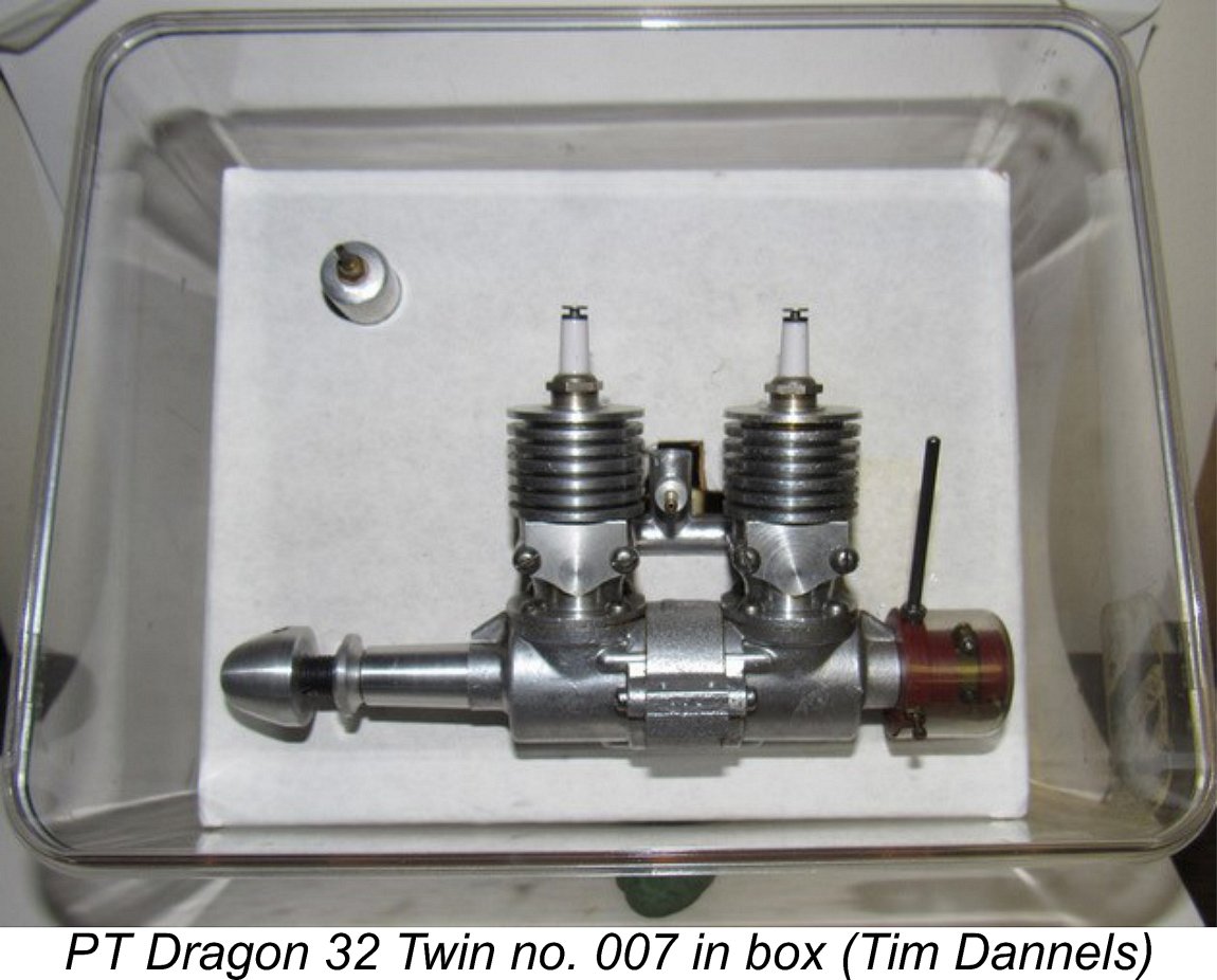
 run.
run. 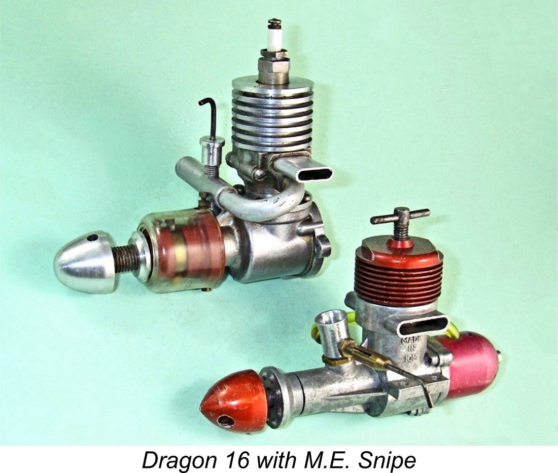 It’s clear that a considerable amount of original thought went into the Dragon's design. Moreover, the quality of the engine's components is considerably higher than its reputation might suggest. We've seen that those components were manufactured in significant quantities, while a noteworthy effort went into the preparation of supporting documentation. All of these factors imply a serious intention to challenge the mainstream model engine market as it then existed.
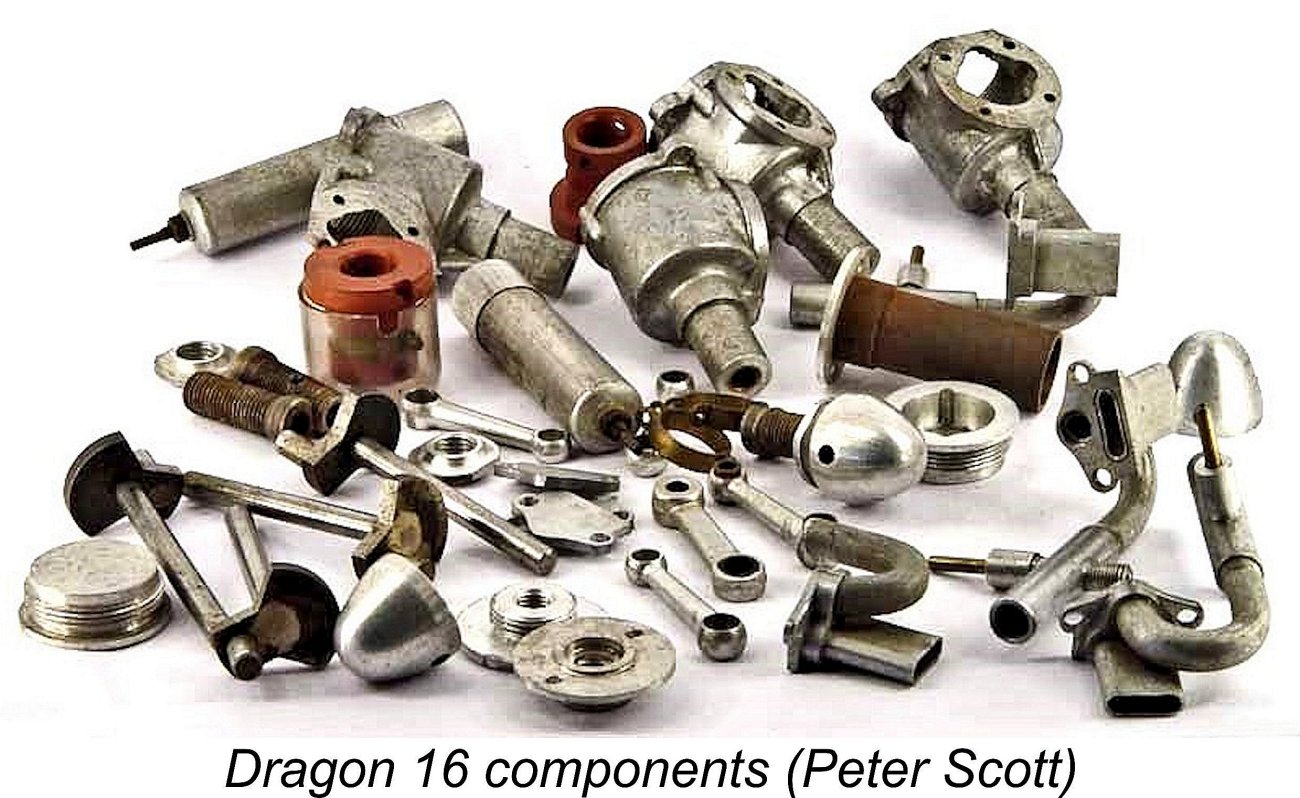 An initial check of my example with a prop fitted revealed that the engine had an excellent compression seal but was excessively “leaky” at the bottom end, matching Peter Scott's experience. Close inspection confirmed that, like the example described by John Goodall, it had been assembled without gaskets or any other form of sealant. As a result, the bottom end leaked like a sieve - it would never run in this condition.
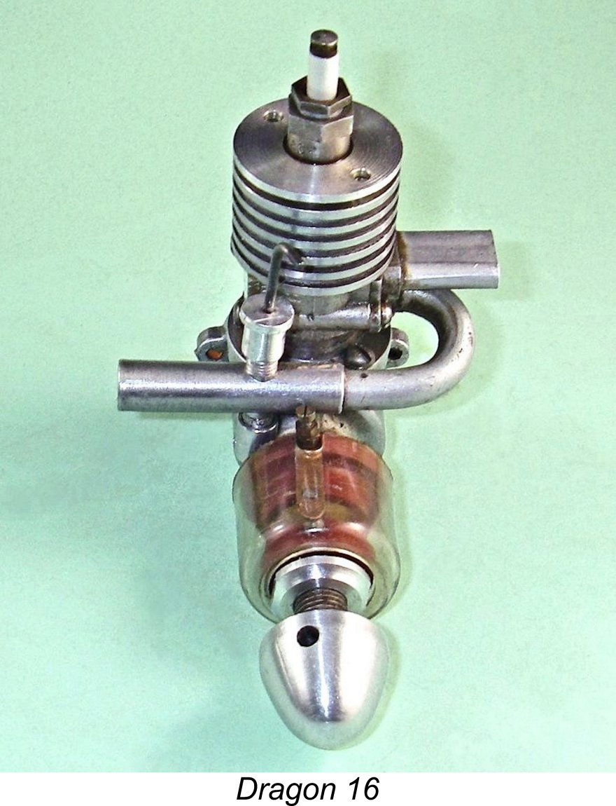
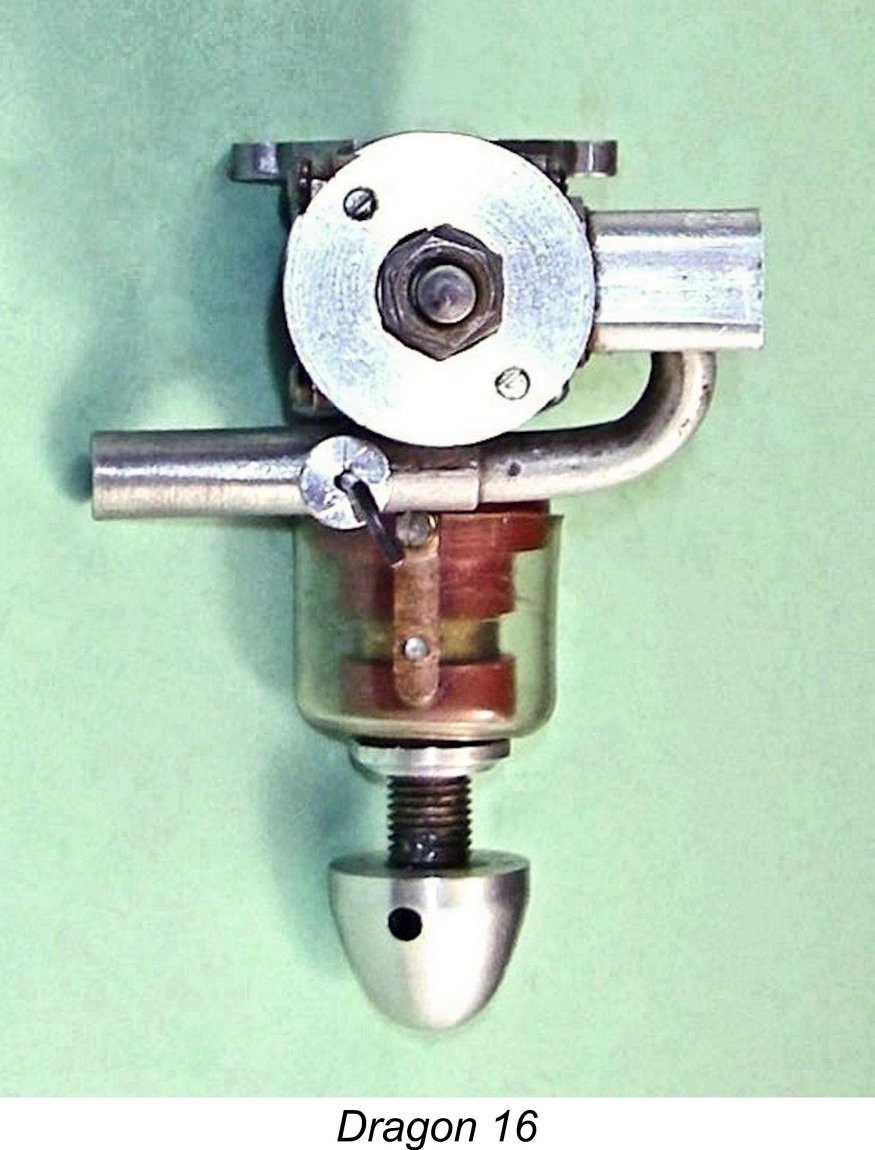 which crosses the front of the engine transversely from right to left and then bends rearwards through 180 degrees to align with the induction port. It is secured to the cylinder by a flange which also accommodates an opening for the exhaust directly above. The flange itself is secured to the cylinder by a pair of 6BA machine screws.
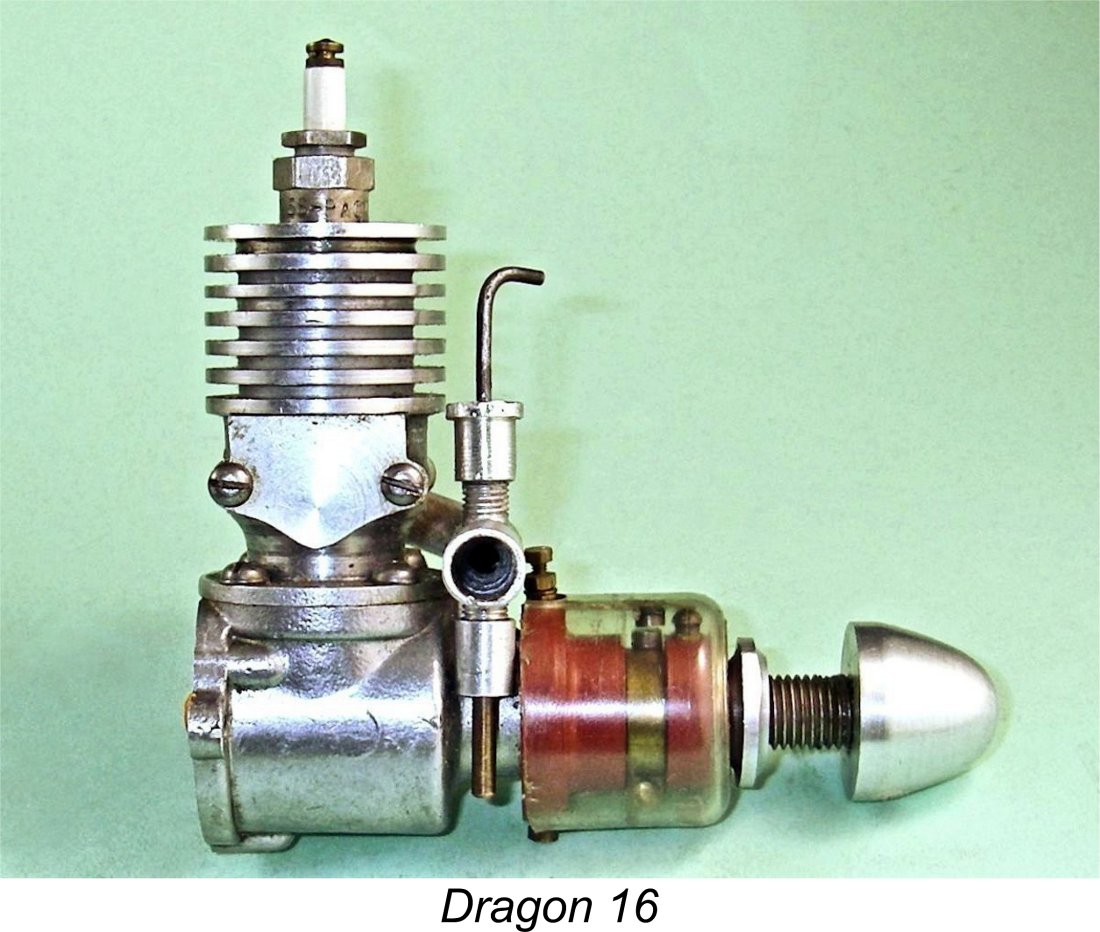 Looking at the engine’s working components, we come across a few more somewhat unusual features. The Dragon 16 is built around two main castings - the crankcase with integral main bearing housing and the upper cylinder jacket, which is secured to the top of the crankcase with four 6BA machine screws. The upper casting incorporates both a bypass channel and openings for both induction and exhaust. The cooling fins are machined into this casting. Both components appear to have been produced by gravity die-casting from permanent molds.
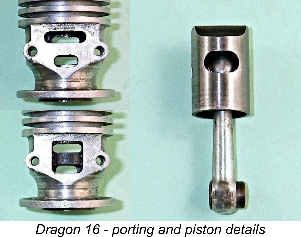
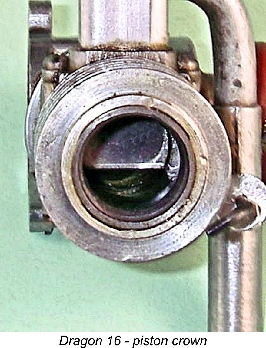 The steel cylinder liner is internally threaded at the top to accommodate the cylinder head. The liner appears to be shrunk in prior to the finishing of the bore. The very long cast iron piston is a beautiful fit in the finely-finished bore - compression seal is outstanding. This is actually typical of this engine - it is far better made than its reputation might suggest. John Goodall actually commented on this very point, and I agree with him completely. The piston crown incorporates a well-formed and smoothly-finished wedge-shaped baffle.
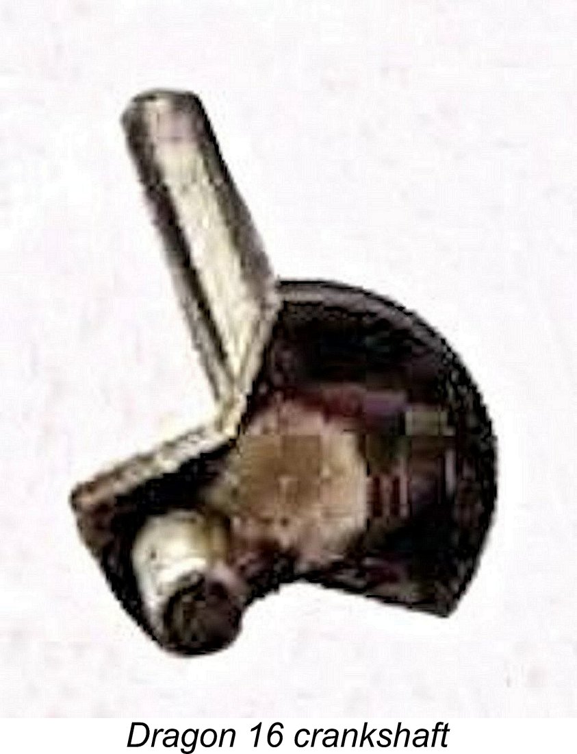 The crankshaft is supported in a very well-fitted bronze bushing. The recessed screw-in backplate is provided with two machined grooves in the wall of its external recess to provide purchase for removing or tightening it.
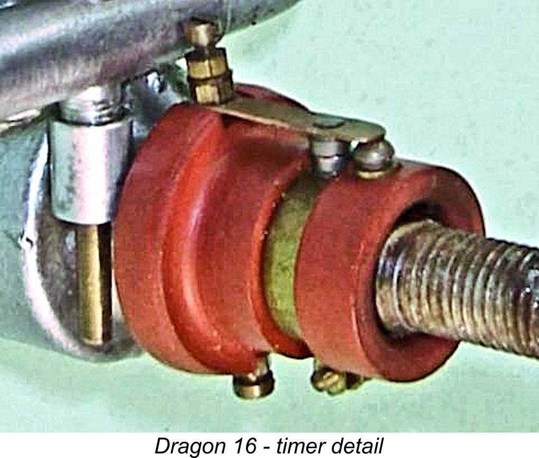 Very unusually, the timer carries terminals for both the ground and the timer wire - the timers on most sparkies are connected directly to the engine’s structure which serves as the ground. In this instance, because the ground terminal is mounted on the non-conducting timer base, it would be necessary to make an aditional wire connection to the main engine structure to complete the trigger circuit of the solid state ignition system generally used these days.
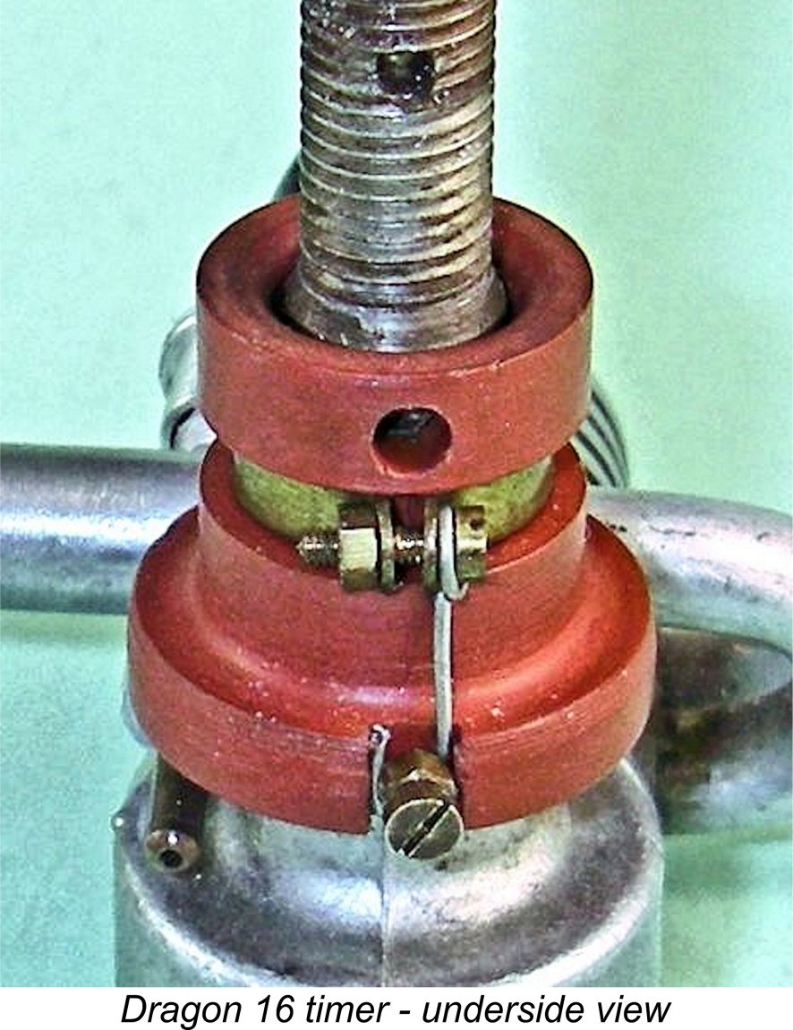
| |