
|
|
The Classic Fuji 29 and 35 models
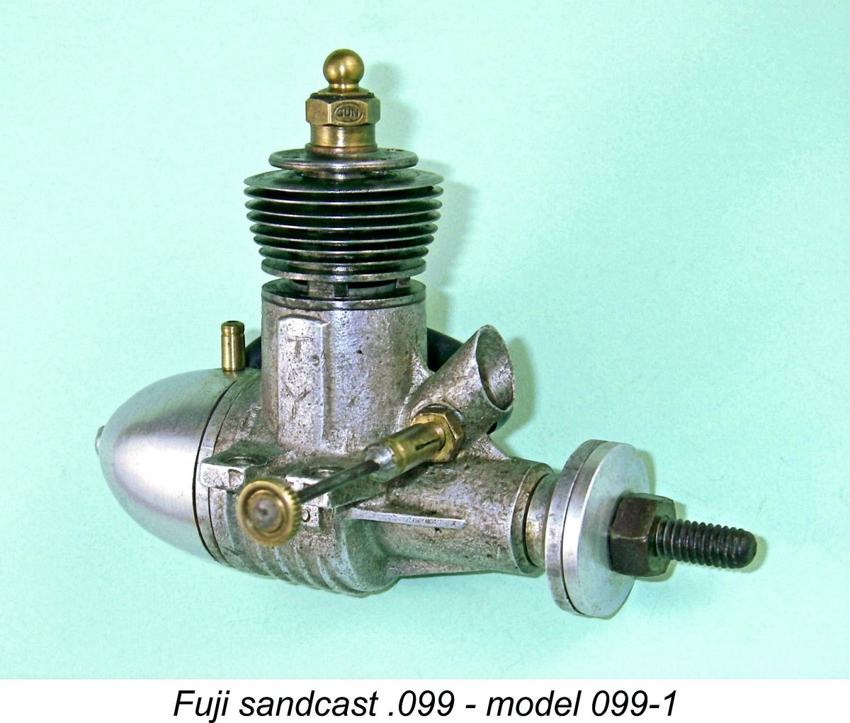
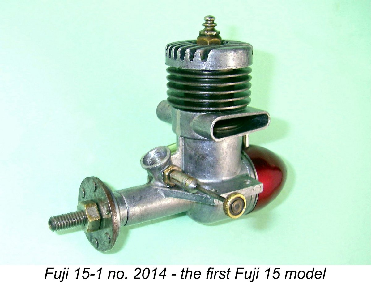
Like their smaller .099 cuin. siblings already catalogued in an earlier article which may still be accessed on the late Ron Chernich’s “Model Engine News” (MEN) website, the .29 models were there throughout the life of the Fuji range, while the .35 cuin. series was not long in joining them. Indeed, Fuji was among the first Japanese manufacturers to offer a glow-plug motor of .35 cuin. nominal displacement. These are thus significant engines in the history of the Fuji range. The early products of the Fuji enterprise have always attracted attention from model engine enthusiasts and collectors due to the company’s marked tendency to plough its own furrow in design terms. Although they were no balls of fire as far as performance went, the majority of those earlier models were refreshingly out-of-the-rut designs possessing a charm which was all their own. They were also very well made, especially where it counted. I myself have long been attracted to the range on the basis of these qualities, making it a pleasure to research and write about them. A summary history of the company's unique twin-stack .15 cuin. models will also appear in due course on this website.
The company appears to have been located in the Kyobashi district of Tokyo, a very long way indeed from Mount Fuji. This being the case, the choice of the Fuji name for the range may seem a little strange to a non-Japanese reader. It's readily apparent that the name is not derived from any direct geographic association with the iconic Japanese mountain of that name. However, there is a connection nonetheless. Mount Fuji has great cultural significance for the Japanese people. It is viewed as the “peerless mountain”, being seen in fact as a spiritual entity in its own right and being referred to accordingly by the honorific name of "Fuji-san" in token of its deep spiritual significance. Accordingly, the name “Fuji” applied to a product or a business denotes “quality” or “peerless” to the people of Japan. It thus comes as no surprise to find that the name is very commonly used by Japanese commercial enterprises wishing their name to impart a sense of quality to their products or services. Quite apart from the well-known Fuji Film company, there’s even a highly-regarded Japanese apple that bears the Fuji name!!
The Fuji 29 and 35 models are so closely related that it makes no sense at all to treat them separately, hence my decision to cover both series in a single article. As with the .099 models discussed in detail elsewhere, unravelling the history of these two series has proved to be no easy task. To a very large extent, this is due to the almost complete absence of any information in the English language prior to 1954, when the Western modelling media first began to pay serious attention to model engine developments in Japan. Accordingly, I must emphasize the fact that the dates given below are my best estimates only, based on the relatively limited information presently available. It's highly likely that some of those dates are a bit off the mark, and I would welcome any authoritative and well substantiated corrections to what I've Another factor presenting difficulties to the researcher is the extreme rarity of some of the earliest designs. I've done my best to capture all of them, but I recognize the fact that there may well be models in these displacement categories of which I remain blissfully unaware! As always, any assistance in filling gaps or correcting errors in what is presented here will be very much appreciated and fully credited. One problem that always rears its ugly head when reviewing any particular series of engines produced under the Fuji banner is the fact that until the early 1960's Fuji themselves never bothered to assign any individual identities to successive variants of their products. Their first five .29 cuin. designs, for example, were all simply designated as the Fuji 29 despite the fact that the series passed through a significant sequence of highly individualistic design variations, as we shall soon see. To get around this problem, I have once again applied the model identification system that I used Thus the 29-1 model is the first known design variant in the Fuji .29 cuin. sequence, while the 35-3 model is the third known design variant in the Fuji .35 cuin. series. I have chosed to assign a separate series to the disc rear rotary valve (RRV) 29 models, since I see them as quite distinct designs from the main crankshaft front rotary valve (FRV) sequence. I trust that those sharing my interest in the Fuji range will find this system useful in clearly identifying and dating particular engines from among the bewildering range of different models produced by this remarkably prolific company over the years. Finally, before embarking upon this journey I’d like to pay tribute to my friend, colleague and fellow Fuji enthusiast Mel Reid of Harrogate, England. Although we haven’t corresponded is some years now, I retain copious notes supplied by Mel with respect to the Fuji range with which he was closely familiar. These notes helped me greatly during the preparation of this article. Thanks, Mel!! With the above preamble out of the way, let’s get right down to the task in hand........... The First Fuji 29 FRV Model (model 29-1)
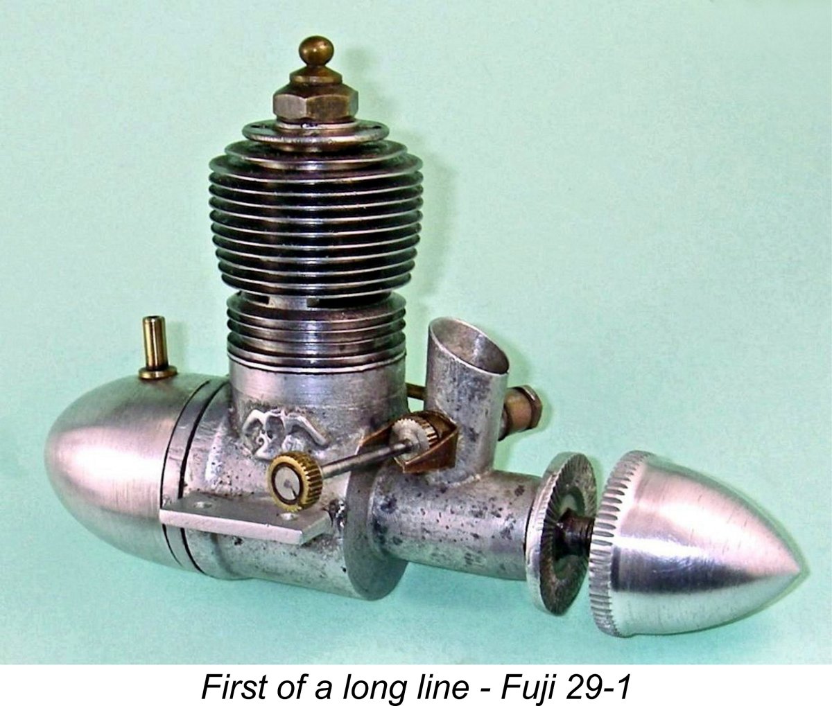
The identification of this variant as the first Fuji 29 model is entirely unsupported by any available documentation in the English language. However, its identification is beyond dispute, since several illustrations exist in the form of Japanese language Fuji advertisements and Japanese modelling media articles about the Fuji range. These clearly depict the engine which I have chosen to designate the Fuji 29-1. Note that the illustrated example in the advertisement below appears to have a 3/8-24 American O&R glow-plug fitted! Presumably Japanese-made glow-plugs were in short supply as of early 1949. The large Japanese characters at the top of the advertisement stand phonetically for "Fuji 29 B Engine" in the Katakana script used in Japan to express technical and foreign terminology.
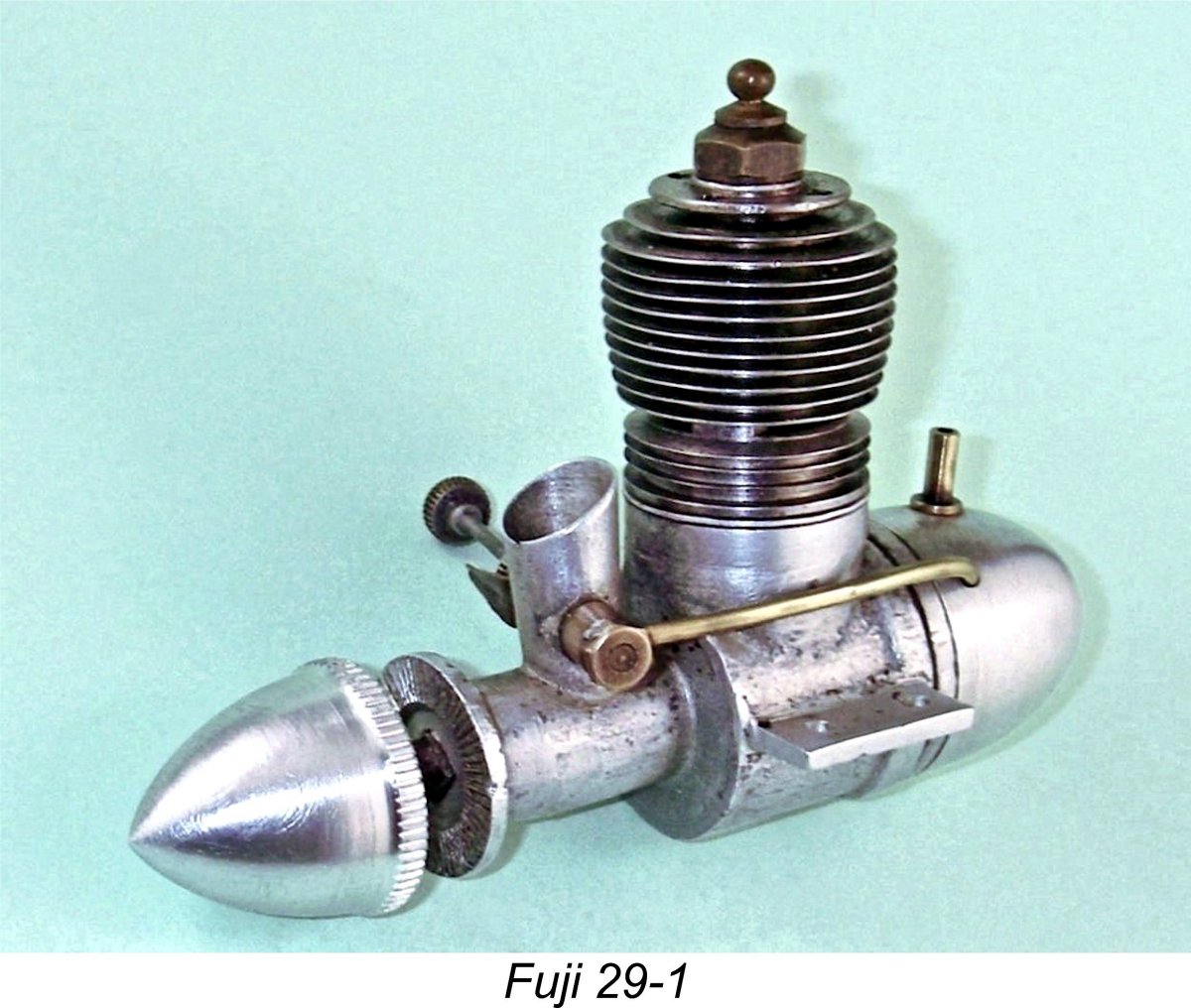
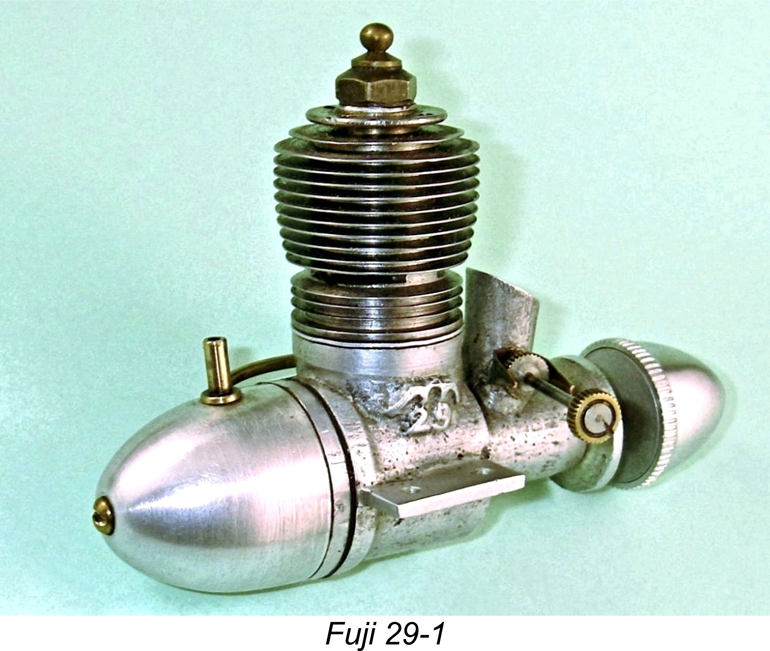
I’ll spend some time describing this introductory model because it was the starting point from which all of the subsequent Fuji 29 models were progressively developed. The engine is a very simple and lightweight 4.96 cc (.303 cuin.) plain bearing crankshaft front rotary valve (FRV) radially-ported glow-plug motor having a number of distinctive features. For one thing, it incorporates a cast-iron cylinder having a blind bore allied to thin integrally-machined cooling fins. For another, it sports a 3/8-24 glow-plug, a fitting which was abandoned fairly early on in the glow-plug era in favour of the familiar ¼-32 item. My example is fitted with a Japanese-made Sun glow-plug. The engine is based upon a very plain brush-finished sand-cast crankcase with a screw-in backplate which is itself machined from a sand-casting. The castings are a In addition, there is a notable absence of any reinforcing webbing on the crankcase - indeed, a certain minimalist design philosophy is evident throughout. Such a minimalist design approach seems to have been very much de rigueur among Japanese model engine designers of the period – if a feature did not contribute to improved performance, it generally wasn’t included. At this early stage, structural integrity appeared to occupy a secondary position in the hierarchy of design imperatives. In this context, the absence of any stiffening web to reinforce the seemingly-vulnerable upright induction venturi tube is particularly noteworthy. The axially-located beam mounting lugs are also rather on the thin side in addition to being completely unbraced. In all honesty, I wouldn’t give much for this engine’s chances of surviving a hard crash! Despite the porous castings and the seemingly fragile nature of the design, it must be said that the quality of workmanship displayed in the engine’s mechanical construction leaves little to be desired. All fits and working surfaces are of the highest order throughout, resulting in a unit which seems well able to give long and faithful service provided it isn’t over-stressed and is kept out of hard impacts with the big green thing.
The engine weighs a not-unreasonable 207 gm (7.31 ounces) all complete with plug, tank and metal fuel tubing as illustrated. The massive and operationally redundant spinner (see below) accounts for 20 gm (0.71 ounces) of this total. The extensively machined screw-in cast-iron cylinder has a blind bore with integral head along with integrally-formed cooling fins. There are eleven such fins above the exhaust ports (not including the thick cylinder installation flange at the very top of the cylinder) and a further three fins below. These fins are very much on the thin side, hence doubtless being somewhat prone to damage through accident or careless treatment. On this first model, the head is centrally drilled and tapped to accept a 3/8 x 24 thread glow-plug.
Removal of the cylinder provides a look at the engine’s interior, where some more interesting features may be observed. The rod is of hardened steel and is unusually skinny for an engine of this displacement - another minimalist design feature. The cast-iron piston is extremely lightweight and is machined away internally to logical limits, leaving only a pair of narrow gudgeon pin bosses to relieve the very thin walls. However, the piece de resistance in minimalist terms is the gudgeon (wrist) pin! The working diameter of this component where it passes through the con-rod small end is only 2.5 mm - a new record for a 5 cc engine in my personal experience! Even more individual is the method of installation of the pin. One end is externally threaded 3 mm and has a slot for a screwdriver. The balance of the pin is left plain at the 2.5 mm working diameter.
The reason for such a set-up is made plain when one looks once again at the transfer porting. Since the cylinder is of the screw-in variety, there’s no way in which its annular position can be guaranteed upon assembly without the tedious use of individual shimming on a trial-and-error basis. Hence some form of fixing for the gudgeon pin is necessary to prevent possible fouling of the bypass passages. The screw-in design described above is clearly the designer’s response to this issue. The arrangements for seating the cylinder on the crankcase are interesting. A thin soft aluminium alloy spacer having thin fibre gaskets above and below is sandwiched between the upper crankcase deck and the lower face of the cylinder installation flange. The intent of this must surely be to provide the means for easy adjustment of the port timing and compression ratio by using metal spacers of differing thicknesses to raise or lower the cylinder. This raises the possibility (and it is no more than that) of this particular example being an experimental unit which was used by the designer to finalize the most effective cylinder height through experiment. There’s no question that the spacer is an original feature of my particular engine - in its absence, the transfer ports on this example barely open! Moreover, the compression ratio would become unacceptably high for an engine of this type. As set up with the spacer, the compression ratio is around 7:1 by direct volumetric measurement – an entirely reasonable figure. This said, it bears repeating that images from Japanese sources indicate that not all examples of this model were fitted with this spacer. A somewhat parallel arrangement was used by Hope for the head seal featured in their very rare Hope Super 60 racing model, of which more elsewhere. We shall have occasion to recall this later.
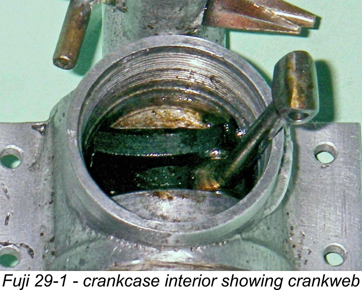
Nonetheless, removal of the cylinder revealed the details already described, also allowing an inspection of the crankweb. This proved to be counterbalanced both by crescent-shaped cutaways on either side of the crankpin and by a hefty counterweight on the opposite side from the crankpin. Given the relatively lightweight reciprocating components, one would expect vibration along the bore axis to be relatively minimal at the expense of some lateral vibration. It was possible to determine that the internal gas passage in the crankshaft has a diameter of 7 mm in conjunction with a main journal diameter of 10 mm. A look down the intake venturi tube reveals that the induction port in the crankshaft is of the rectangular variety, which tends to promote more rapid opening and closing of the induction system. The throat diameter of the venturi tube is 6.5 mm. The spraybar (which appears to be original) is a relatively substantial item having an external diameter of 3.5 mm. It is externally threaded at both ends as well as being internally threaded for the needle. At the fuel delivery end, a banjo union is secured by a nut to provide a right-angle connection for the fuel line. This example was missing its tank as received, and the original brass fuel line had been replaced with a stub connection for use with flexible fuel tubing.
The engine had no tank as received, although illustrations from Japanese advertisements prove that it did originally have a tank of typical Fuji streamlined shape. They also prove that the fuel line was formed from 2 mm brass tubing as opposed to the more familiar flexible tubing. This was in fact a fairly typical approach among Japanese manufacturers of the period – flexible fuel tubing was apparently in short supply in early post-war Japan. The tank and fuel line in these images are of my own making.
Close inspection of the available advertising images confirmed that the spinner was provided with a raised serrated lip at the rear to allow it to be finger-tightened quite securely. In the absence of an original component to copy, I've chosen to reproduce this spinner to "look-alike" standard as part of the restoration of my own example, recognizing the extreme improbability of its being dimensionally accurate. It does complement the streamlined tank very well indeed, so I'm happy! This feature of the Fuji 29-1 makes it unique among the classic .29 cuin. engines marketed by Fuji - it was their only such product (as far as I'm aware) to feature a spinner as supplied. Of course, the nut and prop washer supplied with the engine are completely adequate on their own to secure the prop, making the use of the spinner unnecessary from an operational standpoint as well as adding some extra (and unproductive) weight. I suspect that few of these spinners were actually used by their owners, and most will have been lost over time. The one positive outcome of the use of this component would have been to allow for a certain amount of trimming of the model's nose weight.
I've actually bench-run this engine in the past, although I've never subjected it to the rigors of a full test. Based upon my notes taken at the time, the engine's handling qualities may perhaps best be summarized by stating quite truthfully that I gave it 7 runs and only needed 7 flicks to do so! My notes confirm that following a light prime through the open exhaust ports, the engine literally started first flick EVERY time, with no tendency to backfire, no sagging and no trace of a misfire at any speed. What a sweetheart of an engine!! Response to the needle was outstanding, making it very easy to establish an optimum setting at all speeds tried. Running was exceptionally smooth throughout. No wonder it seems to have been an immediate success I previously noted the heavy counterbalancing of the crankweb coupled with the relatively lightweight reciprocating components. As one might expect, this had the effect of keeping vibration well under control, and the engine was unusually vibration-free in operation, at least in the test stand. It's clearly no ball of fire in performance terms, but it did turn a Taipan 10x4 prop at a seemingly effortless 10,300 rpm on a low-nitro fuel, running the tank out cleanly while doing so. This implies a perfectly respectable output of around 0.280 BHP at that speed. Now, having described the first Fuji 29 in considerable detail and gained an impression of its running qualities, it seems appropriate to step back from our chronological review of the Fuji 29 series to indulge in some interesting speculation regarding the origins of the Fuji 29 and indeed the Fuji enterprise in general. A Possible Hope connection
Firstly, the crankcase design (minimal bracing, near-upright unbraced induction venturi, screw-in cylinder and backplate, etc.) and the style of casting (a bit porous, with a brushed finish) seen in our unknown subject are very similar indeed to the parallel features of the Hope B, although the Hope does have a single bracing web beneath the main bearing. Other features such as the major crankshaft dimensions (apart from the stroke), the rectangular crankshaft induction port, the square-on-shaft prop driver mounting, the needle valve style, the heavily counterbalanced crankweb design, the very skimpy con-rod, the screw-in method of securing the gudgeon pin and the fuel supply arrangements are all common both to the Fuji 29-1 and the Hope B.
As soon as one makes the above connection, it becomes very easy indeed to see the original Fuji 29-1 as a development of the Hope B. Although there are obvious departures in terms of external appearance, the design fundamentals of the two models are strikingly similar. A further indication of a possible Hope connection is to be found in the previously-described composite cylinder base sealing system. It will be recalled that this seal was created using two thin fibre gaskets with an aluminium spacer sandwiched between them. The apparent intent was to allow for adjustments to the compression ratio and port timing. This precisely mirrored the approach taken by Hope in their limited-edition Hope Super 60 racing model which is described elsewhere, although in that case the intent was purely to permit adjustment of the compression ratio to suit different conditions. Further evidence of a possible connection is found in the fact that an original Hope B tank fits the Fuji 29-1 backplate perfectly. Moreover, an original Hope B needle proves to be a perfect match for the Fuji 29-1 spraybar. Finally, the fuel “plumbing” using 2 mm brass tubing is identical to the system seen on the Hope B. Looking at the above factors, it becomes very easy to see the unknown engine as a development of the Hope B by an independent designer. Having said this, I must stress that the above analysis represents nothing more than a set of observations upon which a working hypothesis may be based.
By early 1949 our unknown designer had come up with the subject engine as we now see it and had begun to make it in small quantities on his own account, selling it under the Fuji banner as the Fuji B 29. Incidentally, the name applied to the engine constitutes yet another straw in the wind suggesting a possible Hope B genesis ………the designer may have wanted to stress that this was the Fuji B as opposed to the Hope B! The engine was evidently an immediate success, perhaps attracting investment in the fledgling Fuji enterprise from others and thus enabling the rapid development and expansion of the range. It’s worth repeating once more that the above scenario is purely speculative. Although it seems to me to be entirely consistent with what I’ve observed about the Hope and Fuji designs, it's important to keep in mind that consistency does not constitute proof. It would take some focused research by someone in Japan with the necessary language skills and access to Japanese modelling media of the early post-WW2 period to unlock the true facts of the matter. Still, idle speculation is fun!! In addition, it may start someone better placed than I am to follow up on the stated possibility. Now, back to our chronological review of the classic Fuji 29 and 35 models................... The Second Fuji 29 FRV Variant (Model 29-2)
The engine in Paul’s possession is based upon a modified pattern for the sand-cast crankcase. The main bearing housing now has three bracing webs, one below and one on each side. The mounting lugs are also slightly thicker and have rounded outer corners. Somewhat oddly, the near-vertical intake venturi remains unbraced. To me, it would have seemed logical to provide some support for that as well given the fact that the pattern was being modified in any event. A somewhat more significant design change relates to the cylinder configuration. The initial giveaway is the fact that the revised cylinder has four cooling fins below the exhaust ports, while the original model has only three. The two cylinders are seemingly identical above the exhaust ports. The extra depth of the cylinder below the exhaust ports has allowed the omission of the cylinder raising spacer.
This of course prompted me to look closely at what could be seen of the transfer porting. The 3/8 in. hole for the plug allows the cylinder interior to be both well illuminated and easily inspected, making it possible to confirm that the transfer porting is completely different from that used in the 29-1 model described earlier. There is a continuous channel running around the bore just below exhaust port level. This constitutes a true uninterrupted 360 degree transfer port. It is supplied with mixture by six shallow bypass flutes formed in the lower cylinder wall. The arrangement is more or less identical to that used in the late 1948 K Vulture engines from Gravesend in Kent, England. It was to return again in the mid 1960’s as a feature of the short-lived Japanese “Strong” range.
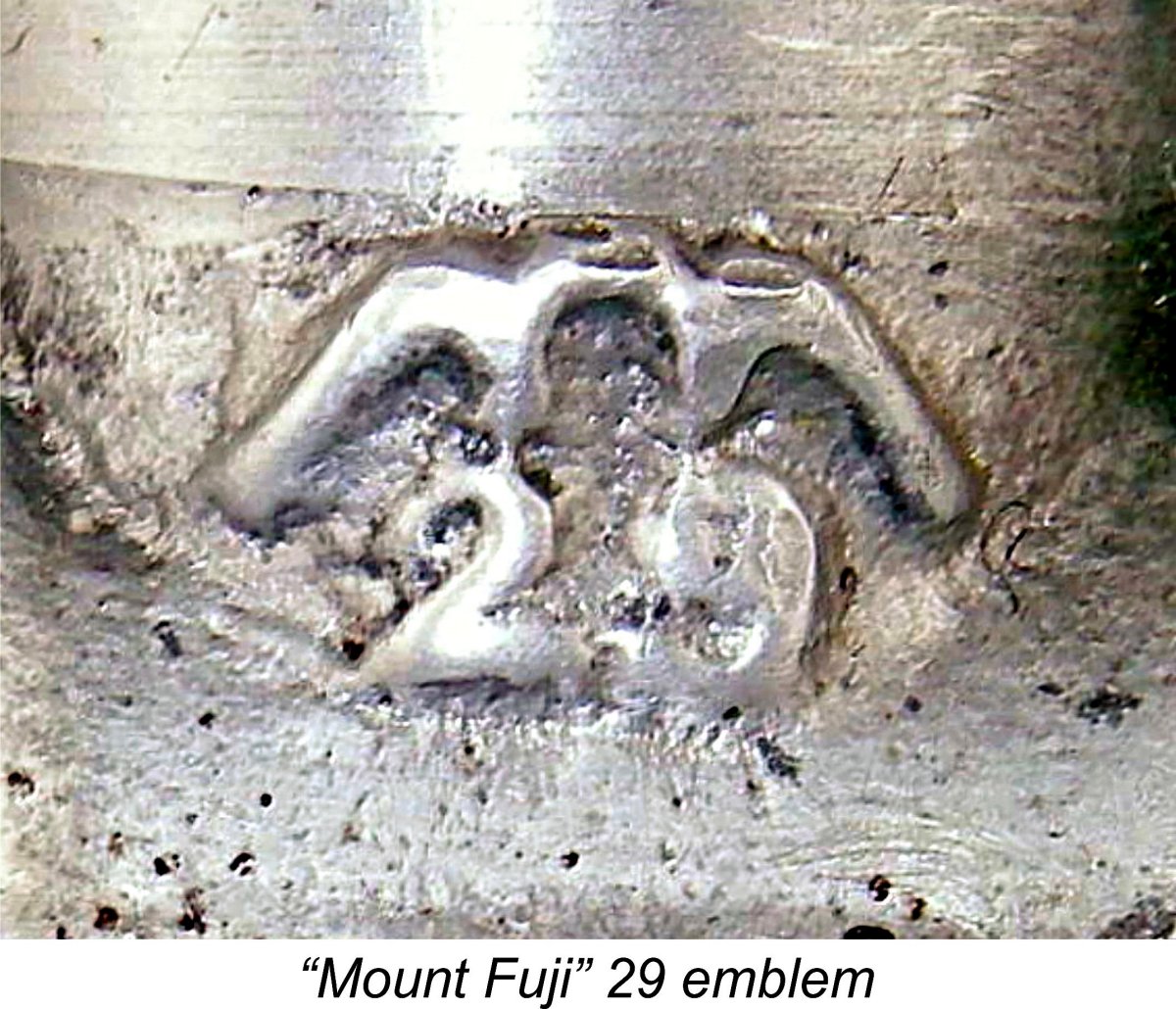
This is almost certainly the explanation for the shallower exhaust ports – raising the lower lip of the exhausts allowed the top of the transfers to be located slightly higher in the cylinder, thus maximizing the transfer period while also minimizing the blow-down period to the extent possible. It also explains the use of the narrower support pillars between the exhaust ports – they no longer have to accommodate any bypass flutes. In addition, it explains the additional cooling fin below the exhaust - the raising of the lower edge of the exhaust ports provides extra cylinder height below those ports. The final obvious difference is the form of the cast screw-in backplate. This is clearly a far more substantial component in the later variant. It’s hard to see this having any functional effect - perhaps the intent was simply to stiffen the rim of the backplate against distortion when fully tightened. The revised model seems otherwise to be little changed. The bore and stroke of this variant continued to be set at 19.0 mm and 17.5 mm respectively for an unaltered displacement of 4.96 cc (0.303 cuin.), still just over the American Class B rules. Paul’s example is missing its tank, but it seems to have had one originally. This was presumably the same as the one used on the original 29-1 model. It may also have featured the spinner seen on the earlier model, although we currently have no evidence for this. Paul’s engine bears the same stylized "Mount Fuji" 29 identification marking as its predecessor, but once again displays no serial number. As far as dating goes, I have no hard evidence whatsoever. I would however suggest that this version most likely followed close on the heels of the original model, almost certainly in mid 1949. There’s no way of knowing how many were produced altogether, but the very small number of survivors suggests that the total wasn't large. The First Fuji 29 RV Variant (Model 29RV-1)
The newly-established Fuji company was no exception to this general trend. Seemingly concurrently with the mid 1949 development of the plain bearing FRV 29-2 model just described, they also came up with a twin ball-race disc rear rotary valve (RRV) “racing” version of the same engine. I’m fortunate enough to have on hand a near-pristine example of this extremely rare engine, which I have designated the Fuji 29RV-1 model. The RRV version was clearly based upon the same crankcase casting as its FRV companion described above. It also used the same cylinder having the revised porting arrangements described earlier in connection Fortunately, such an explanation is readily apparent. It's clear that the integral backplate of the 29RV-1 version now under discussion was produced by the simple expedient of machining off the entire FRV plain bearing section from a standard 29-2 crankcase (without of course drilling and reaming the main bearing!). Vestigial traces of the original FRV housing are clearly visible on the integral backplate of the 29RV-1 model, as pictured at the right. Once this was done, the backplate was completed by drilling and tapping the resulting surface for the screw-in brass venturi and the disc valve spindle. The twin ball-race main bearing housing of the RRV version simply screwed into the same location thread that was used for the backplate in the FRV model. A very economical conversion, it must be said. However, it inevitably resulted in the cast-on 29 emblem appearing on the opposite side of the engine. The bore and stroke of this model were unchanged at 19.0 mm and 17.5 mm respectively for an unaltered displacement of 4.96 cc (0.303 cuin.), still over the American Class B rules. Weight proved to be almost exactly 7 ounces (198 gm). The integral head of the bind-bored cylinder continued to be tapped for a 3/8-24 glow-plug.
Nonetheless, it was possible to confirm that the RRV model evidently uses the same steel con-rod and skinny screw-in gudgeon (wrist) pin setup as the 29-1 FRV variant and presumably the 29-2 model as well. The slotted end of the gudgeon pin is clearly visible through one of the exhaust ports. A number of other points arising from the direct examination of this engine seem worth mentioning. The use of a twin ball-race shaft makes it clear that the RRV model was intended to be a “high performance” alternative to the FRV variant. Although it retains a 3.5 mm diameter spraybar, the venturi throat diameter has been increased slightly from 6.5 mm to a full 7 mm. This should improve breathing a little while still retaining adequate suction. The shorter gas passage and quicker cut-off provided by the disc valve should also help. Use of Maris Dislers’ invaluable Choke Area Calculator reveals that the above dimensions provide an effective choke area of 15.048 square mm and a minimum stable operating speed on suction of 6,219 rpm. One would objectively expect this engine to operate at speeds well in excess of this figure.
The disc valve mounting is of some interest. The disc itself appears to be made of aluminium alloy - not the best material for the job, but quite commonly used at the time regardless. The disc is mounted on a steel spindle which rotates with the disc and passes through a bearing drilled in the centre of the integral backplate. The assembly is lightly tensioned by a coil spring. This spring is retained by a nut which threads onto the outer end of the spindle, allowing the tension in the system to be easily adjusted. The spring rotates with the spindle and bears on a thin bronze washer which acts as a thrust plate between the spring and the rear face of the backplate. Overall, I would expect this version of the engine to out-perform the FRV model, albeit probably not by as much as one might expect. In all honesty, I see this engine as more of a high-performance “sports” unit of its day than as a true racing design. This is a matter that warrants testing, to which I hope to turn in the future when time allows. The Third Fuji 29 FRV Variant (Model 29-3)
The general arrangement of the revised .29 cuin. offering was little changed, but many details were altered. Perhaps the most significant change was reflected in the revised bore and stroke dimensions applied to this model. These were now set at 19 mm and 17 mm respectively for a displacement of 4.82 cc (.294 cuin.). These dimensions were to be maintained in all of the subsequent Fuji .29 cuin. models produced during the “classic” era under discussion. The significance of this change lies in the fact that the engines now complied with the AMA Class B rules used in America. It’s clear from this that sales both to the numerous American service personnel stationed in Japan and perhaps within America itself were now see by the manufacturers as being critical to their long-term success.
Another change to the main casting was the cast-on model identification. In place of the former stylized "Mount Fuji" 29 emblem, the engines were now unambiguously identified as Fuji products through the "Fuji" name being cast in relief onto the right-hand side of the crankcase. In addition, serial numbers were added for the first time, as they also were from the outset with the companion .099 cuin. model. The cylinder porting maintained the transfer arrangements described earlier for the 29-2 and 29RV-1 models with its 360 degree circumferential transfer port at the top of the six internal bypass flutes. However, the Fuji 29-4 actually carried this idea further by having what amounted to a similar channel around the circumference of the inner cylinder wall at exhaust port level. This is of course only in evidence at the three supporting pillars, the inner walls of which are relieved to create a space between the pillar and the piston at exhaust port elevation. Consequently, this variant had true 360 degree exhaust porting to go with the similar transfer set-up! The price of this modification was a significant weakening of the three upper cylinder support pillars between the exhausts. These units should be handled with care!
No doubt the reduced stroke had something to do with this, but a further contributing factor was the raising of the top edge of the exhaust ports to restore their original depth, also presumably increasing the exhaust period somewhat. The gudgeon pin on this variant continued to be of the screw-in variety, but now had an increased working diameter of 3 mm. The blind hole in one piston boss was now internally threaded, and the externally threaded end of the gudgeon pin mated with this thread – the same system as before but with the blind boss now threaded This variant of the engine weighed 204 gm (7.2 ounces) with tank and fuel tubing. Like their predecessors, the metal tanks used on this and the following two models appear to have been made of plain aluminium alloy throughout. The 2 mm brass fuel tubing formerly used had now been replaced with flexible tubing, the supply of which had evidently eased in Japan by this time. It must be said that the fine smoothly-contoured cylinder fins allied with the streamlined look imparted by the crankcase/tank combination make this a genuinely beautiful engine, at least in my eyes. For me, it just “looks right”!! The illustrated example s/n 2958 is of this type. It bears the highest serial number of my acquaintance for this model, implying that around 3000 examples of this variant may have been produced before the switch to the version to be described next. The Fourth Fuji 29 FRV Variant (Model 29-4)
The 3/8 in. glow-plugs which were widely used at the start of the glow-plug era from 1948 onwards had been a reflection of the fact that many earlier spark ignition engines used plugs having that thread. Following Ray Arden's introduction of the commercial miniature glow-plug in late 1947, many owners of such engines naturally wanted to convert them to glow-plug ignition. The 3/8 in. glow-plug was quickly developed to meet this demand. However, the former spark ignition engines quickly fell out of use as more efficient purpose-built glow-plug designs were developed, and by 1950 almost all contemporary glow-plug engines on the market were using the ¼ in. plugs, to the point that the supply of 3/8 in. plugs was beginning to dry up. Fuji now felt impelled to follow the general trend. On the basis of these considerations, it appears likely that the change from the 3/8 in. plug to the ¼ in. item took place at some point in mid 1950 after some 3000 examples of the earlier model 29-3 had been made. If this assessment is anywhere near correct, it implies that Fuji had managed to produce and presumably sell perhaps as many as 4,000 examples of all models of the Fuji 29 during its fifteen or so It would appear that the serial number sequence which had been begun with the 29-3 variant was uninterrupted by this change. No serial numbers below 3000 are presently reported for the 29-4 variant, and the highest serial number of my acquaintance for an engine of this type is 8610. It appears from this that perhaps 6000 or so examples of the 29-4 variant may have been manufactured in total. If we assume that the company maintained its quite impressive original production rate of perhaps 3,000 units per year, we might suggest with some confidence that the fourth model just discussed remained in production into the middle part of 1952. Despite the fact that they seem to have been manufactured in fairly large numbers, these engines are somewhat infrequently encountered today. It seems likely that relatively few of the many examples that were clearly made left Japanese shores, creating the impression outside Japan that this model is somewhat rarer than it actually was. The Second Fuji 29 RV Variant (Model 29RV-2)
The 29RV-2 model utilized the same modified cylinder as that seen on the companion 29-4 FRV model, including the use of a ¼-32 glow-plug. However, it followed the lead of the earlier 29RV-1 variant in featuring a twin ball-race crankshaft allied to rear disc valve induction. Unlike the first variant of the Fuji 29RV model described earlier, this new model did not employ a modified FRV crankcase. Instead, it featured a completely distinct all-new sand-casting which incorporated an integrally-cast main bearing housing having accommodation for the two ball-races. A separate bolt-on rear cover was now featured. This was secured to the crankcase using three machine screws.
At present I don’t have access to one of these rather rare models for test purposes, but I have to say that it seems unlikely that this engine would have achieved true “racing” performance levels by the standards of 1950. The limitations imposed by the radial porting and relatively inefficient blind-bore combustion chamber remained unaltered, making it highly unlikely that even this improved version of the Fuji 29 RV posed any kind of threat to the Dooling and McCoy opposition from the USA, the ETA 29 from England and even the competing Mamiya 29 RV from Japan. It seems that most contemporary modellers agreed with this assessment, since this is an extremely rare model today. As stated earlier, it’s likely that this variant appeared in mid 1950. It seems to have remained available for some time, since this version of the Fuji 29 RV appears in a Fuji promotional image showing the range as it existed in early 1953. However, it is missing from a Fuji leaflet dating from later in that same year. It would appear from this that the engine was in limited production for an approximately two-year period ending in mid 1953. It’s quite probable that it was a special-order item made in very small numbers. There is a real mystery regarding the serial numbering on these engines. The only two examples of my present acquaintance bear the confirmed but widely-divergent numbers 1948 and 9480. I have the greatest difficulty believing that 10,000 of these were made over their 24-month production life, and I freely admit to being a long way from understanding the serial numbering sequence for this model. I also have no way of estimating the total production figure for this variant. I only know that it’s rare!! The Fifth Fuji 29 FRV Variant (Model 29-5)
To deal with this problem, the configuration of the Fuji 29 cylinder was changed once again in mid 1952. Presumably hard experience had convinced the manufacturers that the very thin fins of the earlier models were unacceptably fragile and too easily damaged even in normal use. In response, the fins were now made slightly thicker. Since the cylinder length remained unaltered, this required a further reduction in the number of fins above the exhaust ports from nine to eight. A parallel change had previously been made to the companion .099 cu. in. model to produce the 099-2 variant. In all other key respects, the engine remained unaltered, so there is no need to repeat any of the earlier description. The plain unanodized tank which had been featured in this series from the outset continued to be used. However, it's clear that Fuji themselves saw this as a distinct variant, since the engines made with the new cylinder design were numbered in a re-started sequence which now included the prefix letter B in front of the serial number itself.
Assuming that Fuji were continuing to manufacture the 29 model at more or less the same average rate of 3000 units per year, it seems reasonable to assume that the change to the B prefix serial numbering for the 29-7 and the concurrent introduction of the 35-1 model (see below) probably occurred in mid 1952 or thereabouts. A similarly-designed sandcast .19 cuin. model was also introduced at around the same time. Somewhat unaccountably, the .19 cuin. model received a T prefix. The range was expanding! I have yet to encounter a serial number above B2000 for one of these engines. In fact, the highest serial number yet confirmed for the 29-5 variant is B1735. This implies that fewer than 2000 examples of the 29-5 model were most likely made in total. This represents around 6 month’s production if established production rates were being maintained. This is consistent with the other evidence suggesting that this model was replaced in late 1952 by the extensively revised Fuji Silver Arrow (Model 29-6) to be described below. If these deductions are valid, the 29-5 version of the engine is one of the rarer Fuji 29 variants. A New Displacement Category - the First Fuji 35 Variant (Model 35-1)
Now they took a close look at their existing 29-5 FRV model and realized that with a bit of tinkering its displacement could be increased to something approaching the .35 cuin. figure which was by then becoming more or less the standard for control-line stunt flying. So they went ahead and produced a revised design based on their existing 29-5 model but having an increased displacement. The result was the mid 1952 appearance of Fuji’s first .35 cuin. model, which I’ve designated as the 35-1 variant. This was among the first 35’s to be offered by a Japanese manufacturer. O.S. had of course led the way with their .36 twin-stack model, and the now-obscure TOP range had included a well-made and up-to-date .33 cuin. model. However, the new Fuji .35 was the first Japanese engine of that specific displacement.
The cylinder porting of the new 35 design was identical to that used on the companion 29 models, with six internal flute transfers connected at the top by an annular channel running right round the circumference Although the engine was cited as having a displacement of 0.35 cuin., as reflected in the attached factory leaflet entry, the actual calculated displacement based on the above figures is 5.39 cc (0.329 cu. in.), a little under the claimed figure. So in reality, this engine was a 33! Checked weight of this model is 201 gm (7.09 ounces) with tank, more or less exactly as cited by the manufacturer. The factory claimed an output of 0.49 BHP for this model, a seemingly credible claim under ideal conditions. The early examples of this variant used the same plain un-anodized tank which continued to appear on the 29-5 model - illustrated engine number C2788 is of this type. However, in It was likely shortly thereafter that the 35-1 engines began to be fitted with blue-anodized tanks once the existing supply of un-anodized tanks had been used up. The serial numbering sequence was unbroken by this relatively minor change. The companion Silver Arrow featured a red-anodized tank almost from the outset. Most (but not all) engines in this series bore serial numbers which had the letter C added as a prefix. The highest serial number of my present acquaintance is C8587 as illustrated, indicating that this model was produced in quite substantial numbers. Given the fact that it was apparently in production for some 3 years, the average production rate seems to have been of the order of 3,000 units annually. This implies that the production rate for the earlier sandcast 29 models was continued more or less unchanged for the 35. The Fuji 29 Silver Arrow - the Sixth Fuji 29 FRV Variant (Model 29-6) As of the early 1950’s Fuji had clearly begun to take a close interest in world design trends since they were then in the process of making a serious effort to become a player upon the international stage. This imperative must have been brought into sharp focus by the signing of the San Francisco Peace Treaty on September 8th, 1951 which resulted in the post-WW2 occupation of Japan ending on April 28th, 1952. The majority of the predominantly American service personnel formerly stationed in Japan departed forthwith, taking with them a well-funded and hence significant segment of the post-war Japanese domestic market. Thenceforth, Japanese model engine manufacturers would have to survive by supplying the indigenous Japanese domestic market as well as through expansion of their export efforts. This must have underscored the need for any Japanese model engine manufacturers who wished to survive to bring their ranges as rapidly as possible into step with developments on the international front so that their products might have a reasonable chance of competing successfully in the world marketplace into which they were now thrust. In Fuji’s case, they seem to have realised quite quickly that the use of radial-port reverse-flow scavenging was generally viewed as yesterday’s technology, at least as far as engines in the larger classes were concerned.
By this time too, the scale of engine production and the scope of the range had both reached levels at which the use of sand-casting was no longer viable. This would be particularly true if the company was to continue to expand, as it would clearly have to do in order to survive. Production pressures were now sufficiently elevated for the necessary investment in die-casting technology to be deemed worthwhile.
For this reason, the decision was apparently taken to make the switch to die-casting one model at a time, both to gain experience and in the hope that the initial trial would demonstrate that the economics of the revised casting process justified the same production change being applied to other models in the range. In accordance with this policy, the first Fuji model to be produced using die-castings throughout was a comprehensively revised 29 model which appeared in late 1952 in the form of the Fuji “Silver Arrow”. The illustrated engine (serial number SB633) is an example of this model, which I’ve designated as the Model 29-6 for identification purposes.
The die created for the main casting of this engine was quite complex, being apparently made in four pieces. There was a horizontal split at the base of the mounting lugs, and both the upper and lower “halves” of the horizontally-split die were themselves vertically split. The split marks are quite clearly visible on the finished casting despite the application of a hand-filing clean-up process followed by vapour-blasting to an attractive matte finish. Although it is quite recognizably a member of the Fuji family, the Silver Arrow was the first Fuji model to feature conventional loop scavenging using a single exhaust stack in combination with a cast-in bypass passage opposite the exhaust. A single transfer port of considerable width opened into the cylinder from this bypass passage, and a pair of quite large exhaust ports separated by a narrow bridge opened into the single exhaust stack on the opposite side.
All of the latter three models featured screw-in radially-ported cylinders having alloy heads which were simply swaged in place, presumably after the cylinder had been screwed down good and hard. In the case of the Silver Arrow, it was clearly necessary to ensure the correct annular location of the cylinder ports relative to the cast-in bypass and exhaust passages in the case - the screw-in cylinder approach could no longer be used. Instead, the drop-in cylinder assembly was secured by the use of two long screws which One very interesting feature to be noted here is that Fuji didn‘t rely on the material of the case to provide the material for the threads into which the hold-down screws were fitted. If these threads became stripped, a new case would be required. Not good!! Instead, they elected to use two internally-threaded brass collars with flats milled on one side which bore against the case and thus prevented turning. These may be seen quite clearly in the attached images below the cylinder hold-down lugs cast into the case. No need for a wrench to hold a nut while tightening, and a stripped thread merely required the replacement of one of these collars rather than the entire case. Neat, and an idea which some others might have done well to copy! Returning to the cylinder itself, the continued use of a blind bore pretty much precluded the use of a conventional baffle piston as seen on most contemporary loop-scavenged glow motors - no easy way to mill the baffle slot in the underside of the integral head. But Fuji clearly considered the use of a baffle to be necessary with this gas flow arrangement. They got around the difficulty by reviving an old idea - the use of a step baffle in the piston crown allied to a transfer port located correspondingly further down the bore to preserve a sufficient blow-down period.
One consequence of the use of relatively wide exhaust and transfer ports in the cast-iron cylinder was the fact that there was relatively little metal connecting the lower cylinder to the main bore above the ports. In addition, the walls were quite thin, with no fins on the lower cylinder below the ports to stiffen it. Accordingly, these cylinders are a bit fragile - the thin cast-iron pillars holding things together between the ports are easily fractured, as is the very thin lower cylinder wall below the ports. I have personally encountered two examples with cylinders which were fractured in this way. If you must take one of these units apart, please exercise great care! Despite the changes noted above, the new .29 still looked like a bona-fide member of the Fuji family, even down to the streamlined alloy tank and the addition of the vulnerable “twin expansion” mounting lugs - a retrograde step from the previous 29-5 model. Most of the tanks used on these engines were anodized red, but some early examples did appear with plain tanks - I've seen several low serial number NIB examples with such tanks. Presumably these were unused components from the former 29-5 FRV model, which always used a plain tank. Despite the switch to loop scavenging, the Silver Arrow still retained a considerable helping of the design distinctiveness which set the Fuji range apart from its domestic competitors at this time. The engines are a real class act, starting easily and running very smoothly indeed. They are also very well fitted. The original variant was identified by an intertwined “S/A” motif with an arrow passing diagonally behind it which was cast in relief on the left-hand side of the The engines carried a serial number which featured the prefix “BS” (or sometimes “SB”) followed by the number itself. This number appeared on a raised area cast onto the lower right-hand side of the main bearing casting (facing forward). The highest serial number that I've encountered in years of looking is BS1194, implying that this variant was produced in relatively small quantities. Note that the "BS" letters on this example actually appear to be an inverted "SB" strike! Present-day experience confirms that these engines are very strong runners which also handle very well. It must be said however that they do require more than the usual degree of care in use. Apart from the lower cylinder weakness mentioned above, the crankcase with its rather weak “twin expansion” mounting lugs is prone to crash damage - I have seen a number of engines with damaged lugs from this cause. The Fuji 29 Silver Arrow Evolves - the Seventh Fuji 29 FRV Variant (Model 29-7)
While they were at it, Fuji made one other significant change to the main casting. This was a substantial increase in the fore-and-aft length of the “expansions” in the mounting lugs at the mount hole locations. The hole spacing remained unchanged, but there was more metal around each of the mounting holes. This may reflect some experience of lug failure with the original design. It’s actually rather a puzzle why they didn’t revert to the solid lugs of the earlier sandcast Fuji 29-5 and the companion 35-1 model. One supposes that they simply wanted to retain this feature of their "house style". The makers did take advantage of the opportunity to alter the identification cast into the cases. In place of It seems likely that these identification changes were made solely because not enough people knew what the “S/A” emblem stood for and the company decided to be a little more specific in that regard. They were soon to take a parallel action in connection with the “Menasco” Fuji .099 model (099-4) which first began to appear at around this time with only the letter “M” appearing to indicate “Menasco”. The cylinder too was slightly modified. The wide single transfer port formerly used was replaced by a pair of ports with a bridge between them, presumably to improve piston stability near bottom dead centre and also to deal with the previously-noted chronic weakness of the lower cylinder in the earlier variant. The revised transfer ports also opened very slightly earlier than they had formerly. Finally, the cooling fins were given a slightly rounded side profile. Overall, the changes made at this time were more than sufficient to justify the recognition of the revised version of the Silver Arrow as a separate variant. I have assigned the identification code 29-7 to this second version of the Silver Arrow.
Up to the time of writing I have been unable to establish an intersection between the BS and straight numbering sequences, so it’s possible and even likely that the number sequence was uninterrupted, only the BS prefix being dropped when the design changes were applied. It’s known that Fuji did this with other models, so there’s no reason to doubt that they may have done so here. This revised model of the Silver Arrow appears to have remained in production for at least a further 18 months. It was reportedly quite a popular engine in Japan, and the serial numbers which are encountered reflect reasonably respectable sales figures during the engine’s relatively short production life - I have seen serial numbers as high as 5175 for this variant, and they almost certainly went higher than this.
If I’m correct in my assumption that the serial numbering system for the Silver Arrows was continuous for both models, as seems likely, then it appears that perhaps 6000 examples were made in total over a three year period. This implies that production rates had slipped from their former figure of some 3,000 units annually to around 2,000 units per year. Doubtless marketplace competition from the likes of Enya and O.S. as well as internal competition for production resources from the seemingly popular Fuji 35, .049 and .099 models had much to do with this. The production lives of the Silver Arrow and the original Fuji 35-1 coincided with the period during which the corporate identity of the Fuji manufacturers was changed. In 1954 the name of the parent company was changed from Fuji Tokushu K.K to Fuji Bussan K.K. It appears that a subsidiary company was also formed specifically to manufacture the model engine range produced by the company. This latter organization was registered as the Fuji Bussan Co. Ltd. I discussed the implications of this in my article on the Fuji .099 models and will not repeat that discussion here.
The new box was substantially larger than its predecessor and was decorated in a striking brown-and-yellow colour scheme with yellow and white lettering and bordering. Somewhat oddly, the “Co. Ltd.” name appeared on the boxes, while the instruction leaflets carried the “K.K” company designation. The contents were identified by a stamp applied to a white circle included for the purpose, so the same box could be used for a number of models. The former circular trade-mark was dropped from the box labels since its use was no longer required given the “Co. Ltd” company classification now involved. However, the “winged” Fuji emblem was retained and now appeared on the boxes in a far more prominent rendition. Interestingly the Silver Arrow engines themselves continued to bear the earlier name “Fuji Tokushu K.K.” throughout! Presumably as of 1954, plans to replace the Silver Arrow were already in hand and the model was known to be nearing the end of its production life. Consequently, the expense of re-configuring the die yet again was not considered to be justified. Joining the Pack - the Eighth Fuji .29 FRV Variant (Model 29-8) If you've been checking the vertical "progress" bar at the right of your screen, you'll notice that although we still have five variants of the Fuji 29 yet to be covered, we're actually nearing the end of the article! This is because we've now arrived at the point in our tale at which the engines ceased to be Fuji originals having their own unique design characters, instead becoming in essence derivatives of designs by others, most notably Enya. As a result, there's less to engage our interest in them and far less to say about them. We've seen that the Silver Arrow had represented a move by Fuji towards the mainstream of mid-1950’s model engine design in that it was basically a conventional FRV loop-scavenged side-stack model, more or less like all the others. However, it had retained a significant quota of the Fuji “house style” with its very “Japanese” styling and construction, including the retention of the blind bore which was something of a Fuji trade-mark by this time. It also retained the iconic red back tank and the "twin expansion" mounting lugs. All very traditional Fuji..............
The change in design direction represented by this variant was highly significant in that it represented the first really decisive move away from the design originality which the Fuji range had hitherto displayed. Together with its similarly-styled .35 cuin. sibling, of which more below, the revised 29 and its successors looked exactly like what they were - typical mid-sized Japanese glow-plug motors of their day showing little design originality and a very healthy share of Enya influence, even down to the flex needle which appeared for the first time on this model and its .35 cuin. companion. The banner of design originality would henceforth be carried, at least for a time, by the smaller models in the Fuji range from .19 cuin. downwards. These smaller engines continued more or less unchanged at this time, retaining the now-familiar radial porting design layout. The radial port .19 model even acquired twin stacks of its own at a somewhat later date, joining the .15 and .099 models in sharing that iconic Fuji feature. At present I do not have access to an example of the revised 29-8 model. Indeed, this model and its identically-styled .35 cu. in. companion appear to be among the least commonly-encountered Fuji 29 and 35 models today, almost certainly because their production life was relatively short. Their existence is presently known to me solely from their inclusion in Fuji leaflets which came with NIB examples of other contemporary models known to date from 1955. The above image of the revised 29 model (Model 29-8) is taken directly from one such leaflet. Note that the rectangular exhaust stack with rearward-angled plan view had been carried over from the Silver Arrow to the new model, preserving a degree of “family likeness”. However, the tank had been eliminated and the backplate was cast in unit with the crankcase, exactly like the competing Enya models. A welcome improvement, and one that was long overdue, was the elimination of the notoriously-weak “twin expansion” mounting lugs in favour of solid lugs of conventional pattern. Fuji leaflets tell us that the bore and stroke of this version remained unchanged at 19 mm and 17 mm respectively. The revised 29 reportedly weighed 190 gm without tank, exactly the same as the old Silver Arrow with tank. The makers claimed an output of 0.50 BHP for this model. The Second Fuji 35 Variant (Model 35-2)
Accordingly, Fuji repeated the exercise that they had first undertaken in early 1952 - they modified an existing 29 design to yield a displacement of .35 cuin. The approach taken was exactly the same - they stuck with the same bore as on the 29-8 model but increased the stroke to give the larger displacement. The result was an engine that looked more or less identical to the companion 29 model and shared the same bore of 19.0 mm but used a stroke of 19.0 mm as opposed to the 17.0 mm stroke of its 29 companion. Once again, these bore and stroke dimensions yield an actual displacement of 5.39 cc (0.329 cuin.) - a little below the engine's stated .35 cuin. displacement. The weight was more or less unchanged at a cited 200 gm. The company claimed a peak output of 0.59 BHP for this larger model. Once again, I have yet to locate an actual example of this seemingly-rare variant. All indications are that it had a relatively brief production life of no more than 18 months. The Ninth Fuji 29 FRV Variant (Model 29-9)
Bore and stroke of this model were unchanged at 19 mm and 17 mm respectively. However, there were a number of external differences. The bypass on the revised 1957 version was not carried up to the lowest cooling fin as it had been on the previous model but terminated a little below that point. The number of cooling fins on the cylinder barrel was increased, the fins themselves naturally being somewhat thinner in consequence and having a curved side profile in place of the straight profile of the previous model. The collar which had been formed at the front of the main bearing on both the Silver Arrow and its replacement was now far shorter and was not grooved as it had been on both the previous models. The result of these and perhaps some internal changes was a decrease in the weight of the engine from 190 gm (6.7 oz.) to 176 gm (6.2 oz.) - very light indeed for an engine of this displacement. A measure of Fuji’s “house style” was retained through the continued use of a large rectangular-section exhaust stack which was angled to the rear. However, the engine continued to owe far more to Enya influence than to its Fuji heritage.
The illustrated example has a case with a shiny finish, like the one tested by Warring. This is undoubtedly an extremely rare variant - by the time that the serial number reached S1437 (only 1131 units later) the case had acquired a matte finish and some internal modifications had been undertaken to improve performance a little, resulting in the next model in the Fuji 29 series to be discussed in its place below. It seems likely that the model 29-9 variant was produced only in 1957 and had been replaced by the end of that year. The Third Fuji 35 Variant (Model 35-3) In keeping with what was to prove to be their standard practise from this point onwards, Fuji also released a .35 cuin. version of the 29-9 model. I do not have an example of this variant, nor does it appear in any Fuji promotional literature to which I have access. We have only Ron Warring’s evidence supported by the application of logic and the scope of the range which appeared in Fuji's advertising to attest to its existence. This being the case, I'm unable to comment on the bore and stroke measurements for this presently-invisible model. It may be assumed that it looked very much like the companion 29-9 model described above, but that’s as far as I can go at the moment until an actual example turns up. The Tenth Fuji 29 FRV Variant (Model 29-10) By the time that Ron Warring’s “Aeromodeller” test of the original shiny-case model of the Fuji 29-9 was conducted in early 1958, that model had already been replaced by a slightly revised version. Although Warring’s test focused upon the 29-9 model, he did have one of the revised models in hand at the time of the test. This provides very clear evidence to the effect that the original shiny-case version (model 29-9) had a very short production life indeed - it would appear that only 1000 or so examples were likely produced before its replacement by the upgraded matte-case model in early 1958. In consequence, it is one of the rarest of the Fuji 29 models. The revised 29-10 model was externally differentiated from its predecessor only by having a matte-finished case in place of the former shiny unit. However, Warring reported that it had also been modified internally to improve performance, although he did not specify the form that these modifications had taken. This being the case, it seems odd that this variant was not the primary focus of Warring’s test - it was after all the latest version of the Fuji 29! The most likely explanation is that his example only arrived after he had completed his testing of the former design. Warring did go so far as to run some spot tests on the updated model. On the basis of these spot-checks, he reported that the matte-case version (Model 29-10) was about 5% faster than its predecessor on a given prop, which translates into a 16% power increase given the fact that power requirements increase as the cube of speed for a given prop. It would appear that this variant probably got a good deal nearer to the 0.50 BHP claim of the manufacturers for the earlier 29-8 model. Clearly, as with the first two “Menasco” .099 models described in our separate review of the Fuji .099 models, the Fuji company didn’t see the changes between the shiny-case and matte-case models as being sufficient to warrant treating them as separate models with their own numbering sequences - they simply This version of the Fuji 29 appeared in an advertisement in the September 1959 issue of “Aeromodeller” magazine. This advertisement was placed by Holt Whitney and Company Ltd. of Birmingham, who had recently become the UK distributors for both Fuji and Enya. The advertisement claimed that the Fuji engines were then becoming available in Britain “in quantity for the first time”. However, the other models in the picture with the advertisement imply that it was a factory promotional image dating in all probability from 1957. Consequently, it doesn’t help us much in working out how long this version of the Fuji 29 remained in production. The advertisement is also informative in that it helps us to place the Fuji range in context with its Japanese competition in terms of consumer price. Holt Whitney and Company Ltd. were also agents for the Enya range, and their selling price for the then-current Enya 29-IIIB (an outstanding engine by any measure) was a healthy £5 0s 9d (£5.04) without glow-plug. The required plugs cost in the order of 10 shillings (50p), so it would cost a modeller some £5 10s 9d (£5.54) to get the Enya ready to run. By contrast, the Fuji 29 was selling for £3 14s 0d (£3.70) with plug. The Enya was a far more powerful engine, but the Fuji was a perfectly satisfactory sport/stunt powerplant which would appear to have enjoyed a significant price advantage over the competition. Moreover, its quality of construction was more than acceptable. Like the previous model, this version of the Fuji 29 is very uncommon today. The sole example of this model of my acquaintance bears the serial number S1437. I have no way of knowing how many were made in total. The Fourth Fuji 35 Variant (Model 35-4) I may as well come right out and admit for the record that I have absolutely no direct evidence for the existence of this model! However, if Fuji were running true to form, they would almost certainly have released a revised version of the 35-3 model with the improvements which had been successfully applied to the companion 29-10 model just described - they did so in every other case. I have therefore reserved a model identification code in case an example ever turns up, playing fair with the reader by cautioning that as yet there has been no sign of such a variant! It is of course quite possible that such a variant never existed. The Eleventh Fuji 29 FRV Variant (Model 29-11) As I stated earlier, there’s no way of knowing how long the previous 29-10 model of the Fuji 29 continued in production. Only the finding of more serial numbers or some additional factory promotional material would help to resolve this issue. What I can say with considerable confidence is that by the early 1960’s Fuji had updated their 29 and 35 designs yet again. The relative scarcity of the previous two models of the Fuji 29 leads me to suspect that these changes most likely took place in 1959. The only firm reference point that I have at present is the appearance of the revised designs in a Fuji factory leaflet which clearly pre-dates 1964 based on the other featured models. More leaflets, please!!
The new design followed standard Enya practise in using a main casting incorporating the cylinder jacket, crankcase and backplate in unit. The integrally-cast backplate was cross-braced for additional stiffness. The main bearing was carried in a separate housing attached by four screws. The R/C field was now very much in the ascendant, and the new model used a removable venturi insert to allow the easy attachment of an R/C throttle. The needle valve was a flexible-stem unit patterned again very much along Enya lines. This version of the Fuji 29 had no provisions for the mounting of a muffler. Bore and stroke of this model were unchanged at 19 mm and 17 mm respectively. The more massive construction had sent the weight up to 235 gm. The makers claimed a peak output of 0.65 BHP, although it seems unlikely that such an output would have been achieved in practise. Nevertheless, these engines do run very strongly.
Despite this, it would appear that by this time production of the larger engines in the Fuji range had slowed to a trickle. Notwithstanding their many worthy qualities, it seems that the Fuji name simply didn’t have the pulling power required to tackle the likes of Enya and O.S. - people evidently continued to be willing to pay extra for the “name brand” products. A pity, because they missed out on a very good deal! I have direct knowledge of a fair number of these engines, the highest-numbered of which bears the serial number 4959. This implies that total production may only have been of the order of 5,000 units in total. This version of the Fuji 29 still appears in a factory leaflet which must date from 1964 given the fact that the Fuji .099S which was released in that year is in evidence. However, the next leaflet which shows the 1965 twin-stack version of the Fuji .099 also shows the next version of the Fuji 29, to be described below. It thus appears that production of this variant ended in 1965 or soon thereafter. If this deduction is anywhere near correct, the implication is that average production of this model was only around 1000 units annually over its 5-year production life - a far cry from the 3000 figure achieved for the original Fuji 29 models. The Fifth Fuji 35 Variant (Model 35-5) As had become their standard practise, Fuji also released a .35 cuin version of the above model, presumably at the same time in 1959. In this instance, both the bore and stroke were altered. The engine had bore and stroke measurements of 20.3 mm and 17.8 mm respectively for a calculated displacement of 5.76 cc (0.351 cu. in.). Finally, the Fuji .35 had actually attained its nominal displacement! The revised components resulted in a modest weight increase to 240 gm. (8.46 ounces). In all other respects, the engine was more or less identical to its smaller brother. Once again, the makers made a seemingly rather optimistic performance claim - they cited a peak output of 0.70 BHP. It seems highly unlikely that such a figure would be reached in practise. However, these too are very strong runners in actual use. They work extremely well as old-time control line stunt engines. This model appears to have been manufactured in rather smaller numbers than its .29 cuin. counterpart. The highest serial number of my present acquaintance is 2626, implying that perhaps 3000 or so were made in total. Certainly, by the time we get to engine number 3494 we are dealing with the next model in the .35 cuin series. The implication is that the serial number sequence was continued without a break from this model to its successor. If one assumes that this model, like its companion 29-11 variant, had a production life of some 5 years or so, average annual production seems to have been only of the order of 600 units or thereabouts. The engine is good enough that it certainly deserved greater appreciation than that! The Twelfth Fuji 29 Variant (Model 29-12) In around 1965 a few relatively minor changes were made to the basic models just described. Beginning with the next variant of the Fuji 29, we find that provision had now been made for the installation of a muffler. Two tapped mounting holes were provided, one at each end of the exhaust stack rear wall. In addition, the style of script used for the “Fuji 29” model identification on the left side of the crankcase opposite the exhaust stack was different. The script was shorter and “fatter” than that used previously. Finally, the cross-braces which had previously appeared in the integrally-cast backplate were no longer present. In all other respects, the engine was seemingly unchanged. Bore and stroke remained unaltered at 19 mm and 17 mm respectively, and the weight was also identical. The manufacturers were continuing to uphold their seemingly optimistic performance claims as well. However, it’s worth repeating that these engines are very sturdy performers, whether or not they match the maker’s figures. It’s probable that Fuji had become somewhat disinterested in the larger displacement classes at this time, which would explain the relative stagnation of further development. If our estimated production figures cited earlier are anything to go by, it seems that sales of their larger models during this period were barely sufficient to justify continued production. In all likelihood they only continued to offer these models in order to maintain a foothold, however tenuous, in these “prestige” displacement categories. At present I have access to only one example of this model, bearing the serial number 6256. This implies that the serial number sequence was continued without a break from that of the previous model. I have no way of knowing how long this variant remained in production or how many were made in total. The Sixth Fuji 35 Variant (Model 35-6)
The highest serial number that I have available for this model is 4231. As stated earlier, the serial numbering sequence seems to have continued without interruption from the previous model to the 35-6 variant. Once again, I have no way of knowing how many examples of this model were manufactured. However, I noted earlier that sales of the larger Fuji engines seem to have fallen off substantially by this time and that the development focus was much more on the smaller models which were presumably continuing to sell reasonably well. Conclusion
Accordingly, this ends our retrospective look at the largest engines made by Fuji during the “classic” era. I hope that you’ve found something of interest in these pages! The early models in the series just described were refreshingly out-of-the-rut designs that deservedly attract a great deal of collector interest today. It’s a pity that the later models never really appear to have caught on during the period from the late ‘50’s onwards when Fuji was making determined efforts to penetrate international markets, since they were well-made, dependable and very user-friendly units which were reasonably priced and well able to give excellent service. In all probability it was the fact that Fuji was widely seen as an “economy” range that put people off them - they assumed that low prices coupled with the residual stigma attached to the “Made in Japan” label must mean poor quality. I hope I’ve shown that this perception was totally unjustified and that the Fuji engines in general represented excellent value for money. Too bad that more modellers didn’t catch on at the time ……. a lot of people missed out on some very good deals! I’m certainly glad that I wasn’t one of them!! _____________________________ Article © Adrian C. Duncan, Coquitlam, British Columbia, Canada First published June 2018 |
 In this article, I’ll return to Japan to tackle the very significant challenge of providing a summary of the largest engines produced by the Fuji enterprise during the “classic” era - the closely-related .29 and .35 cuin. models.
 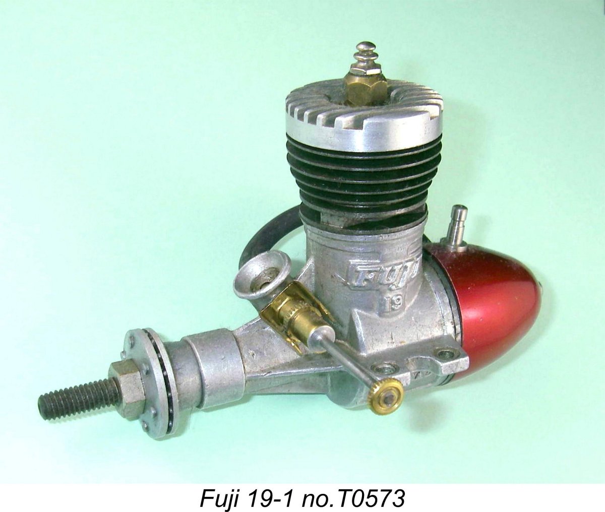 The leaflets and box labels associated with the earliest Fuji products confirm that the original manufacturer of the range was a Tokyo-based company known as Fuji Tokushu Kiki Work. This translates more or less into "Fuji Specialty Machinery Works".
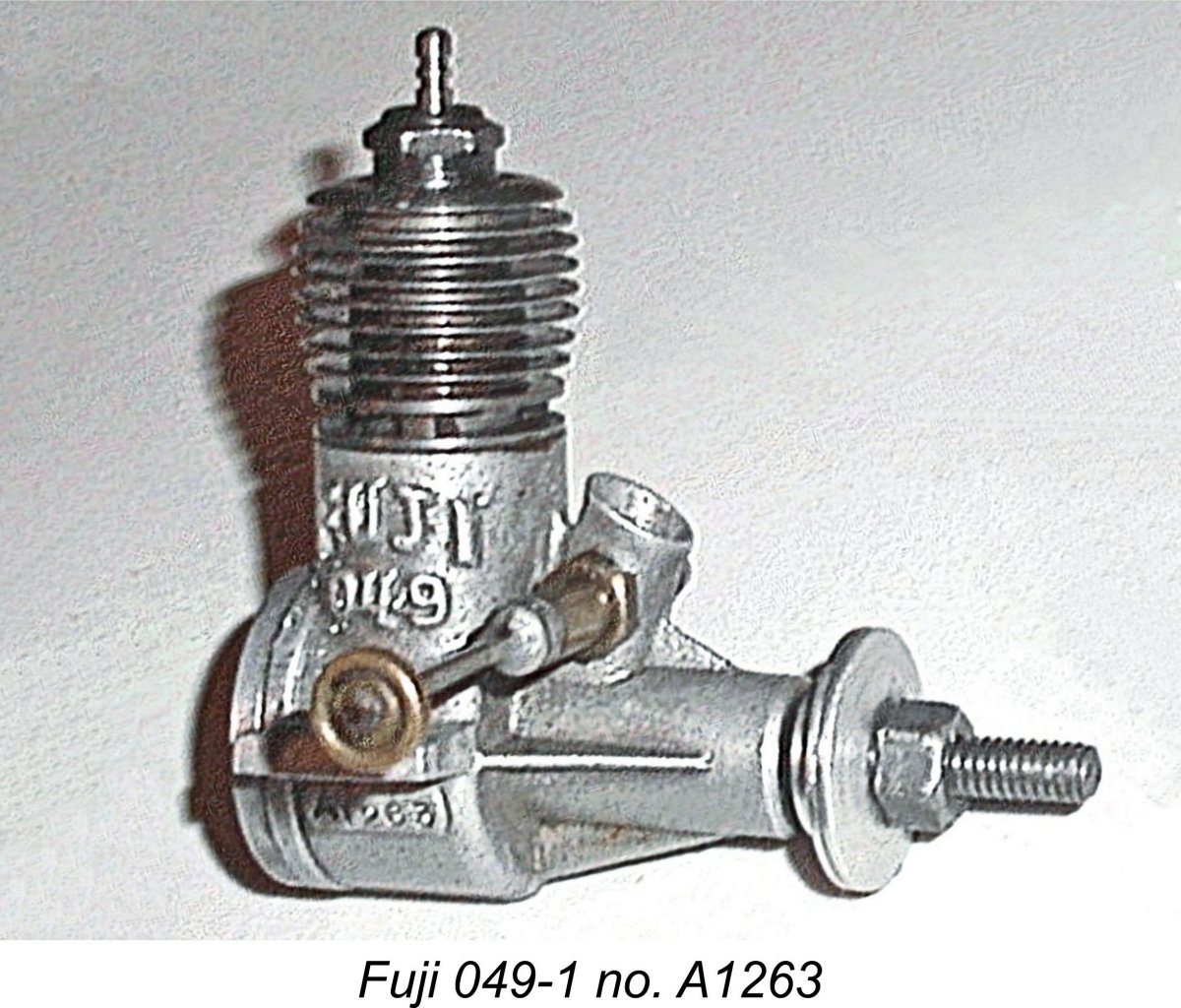
 I noted in my earlier article on the
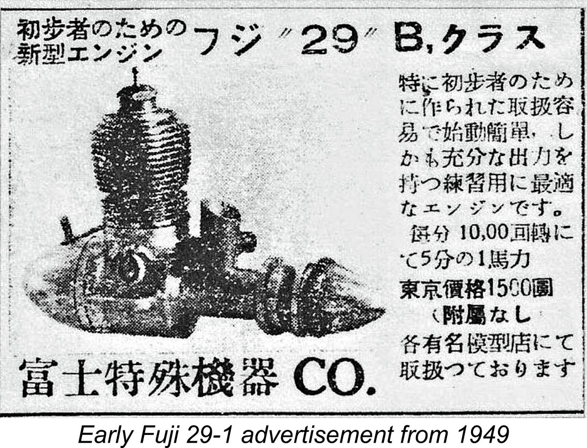
 Measured bore and stroke of this unit are 19.0 mm and 17.5 mm respectively for a displacement of 4.96 cc (.303 cuin). These figures are significant, since they put the engine just above the 0.299 cuin. maximum displacement for the American Class B rules, although taking full advantage of the 5 cc (0.305 cuin.) displacement limit allowed under Japanese and European class rules. I’ll refer to this fact again later in this article.
 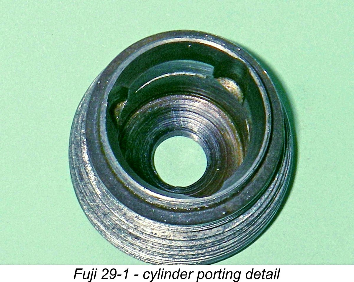 Cylinder porting consists of three fairly deep internal flute bypass passages which extend up the cylinder wall into the three columns which separate the three sawn exhaust ports. This arrangement allows the transfer ports to overlap the exhaust ports, with a small degree of overlap in fact being provided.
 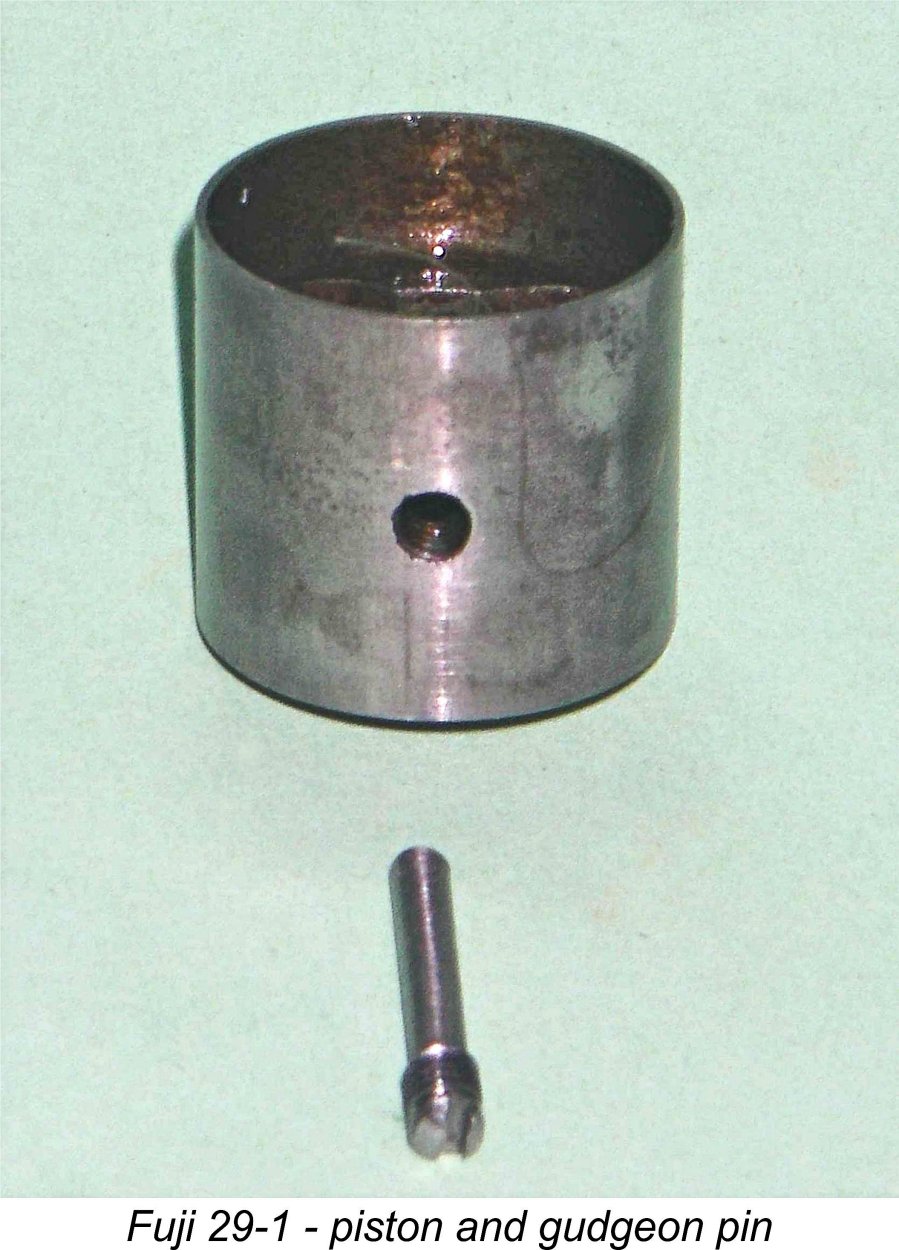 The pin is inserted plain end first through a threaded hole in one of the piston bosses, from which it passes through the con-rod small end bearing and then engages with a blind unthreaded 2.5 mm hole in the opposite piston boss. The external 3 mm thread at the other end of the pin then engages with the matching thread in the other boss, allowing the pin to be screwed home tightly using a screwdriver in the outer (slotted) end.
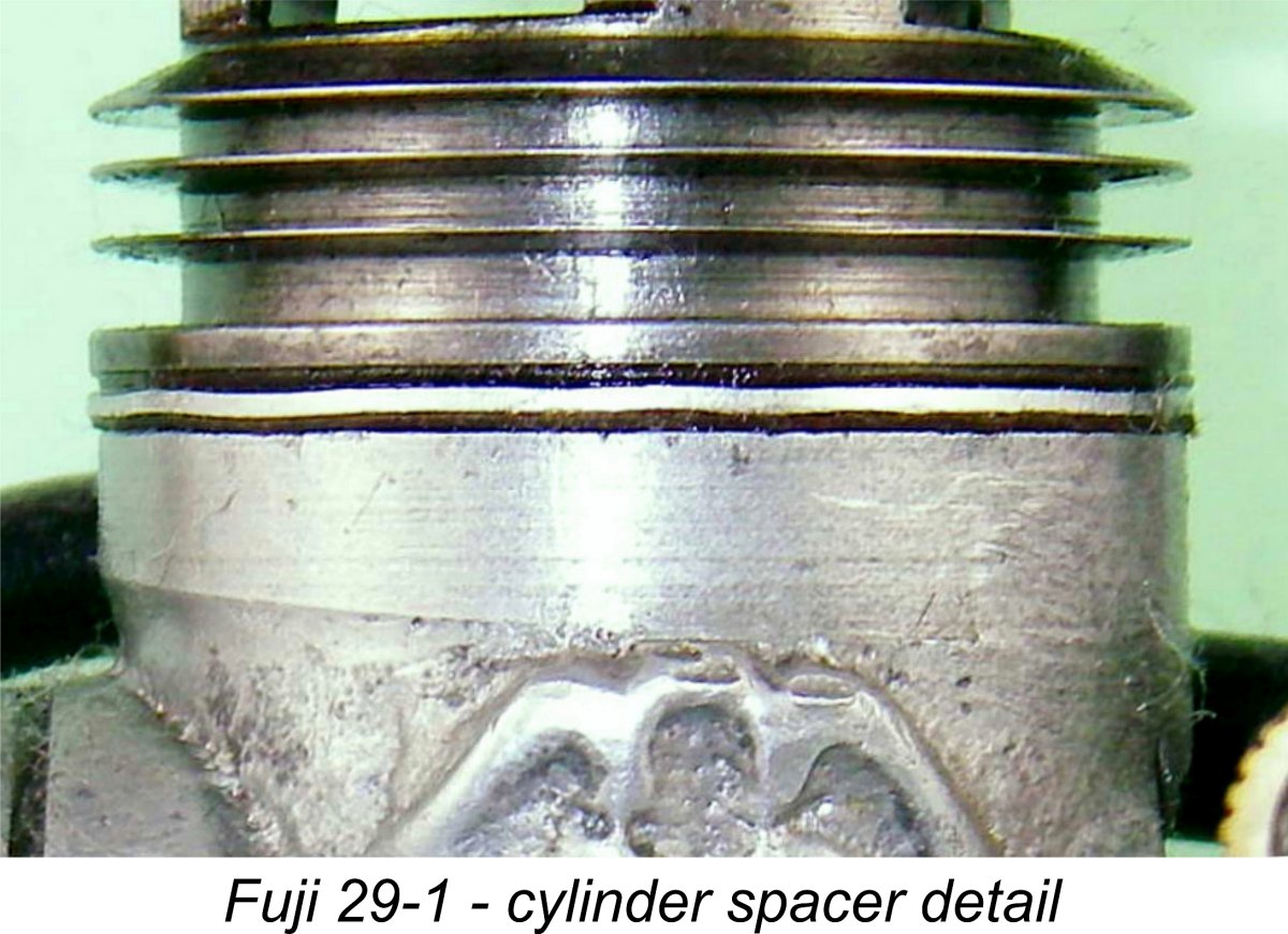
 When my example of the engine was received following its acquisition through eBay, I naturally wanted to tear it down all the way to allow for full documentation. The cylinder unscrewed with minimal problems, but the backplate proved to be effectively “glued” in place courtesy of some well-hardened castor oil residue - even using heat, I was unable to shift it by “fair” means. In view of the engine’s seeming rarity and fragility, I wasn’t prepared to risk damage, so the backplate stayed in place.
 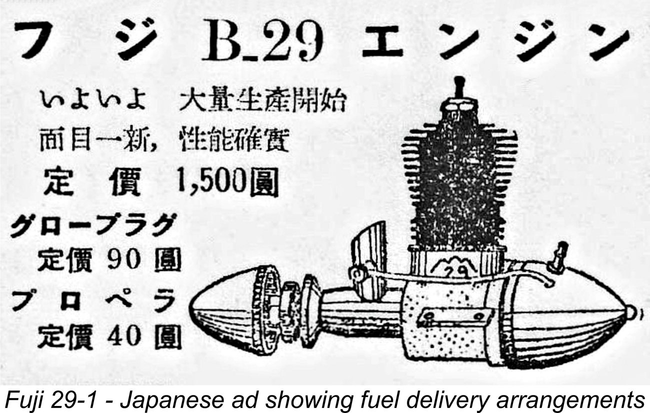 At the needle end, a two-leaf bronze spring clip for needle tension is secured by a nut. The needle itself is externally threaded M2x0.4. It has both a serrated disc which engages with the spring clip for tension and a control knob at the outer end. The entire assembly on this example appears to be original.
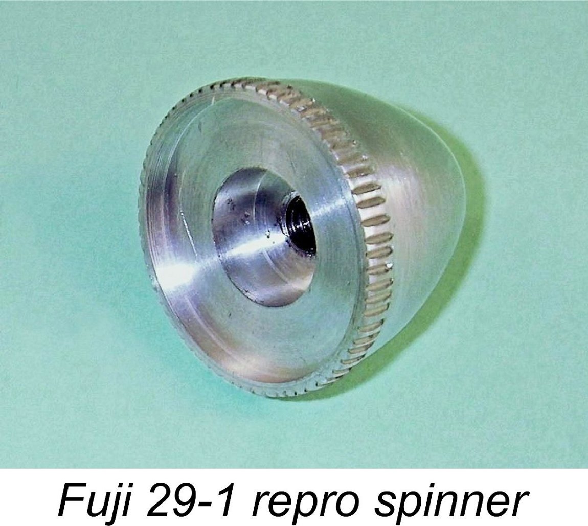 The same may be said of the spinner which appears in the images of my example of the engine. B
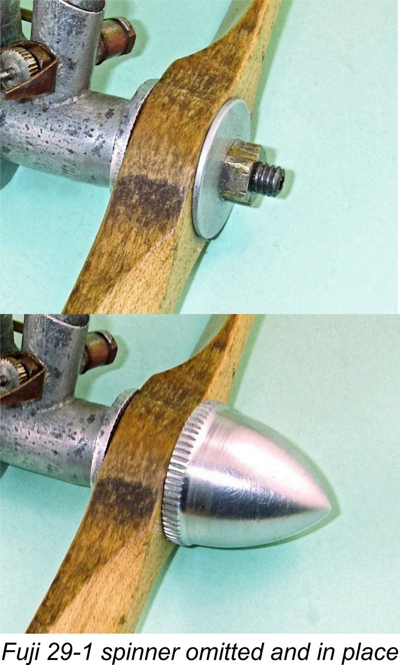

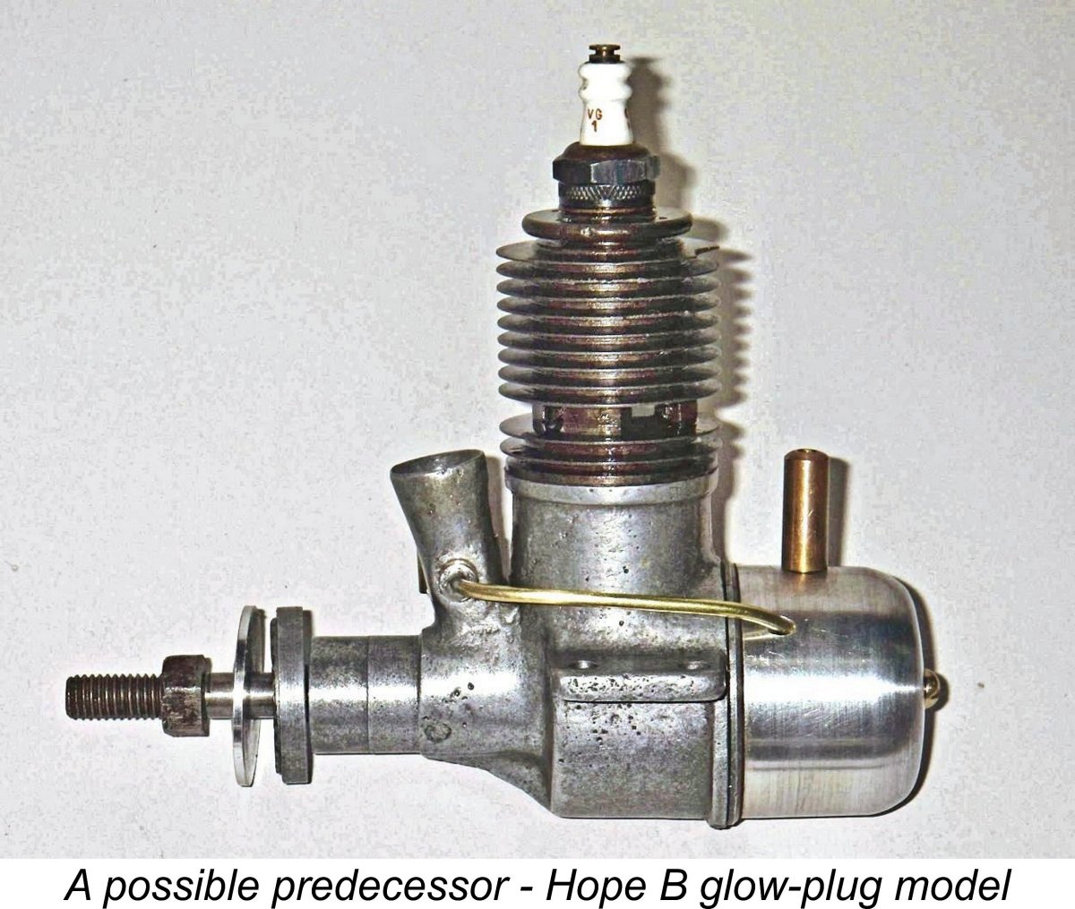 Long-time readers of my articles both here and on MEN may recall my earlier contribution to MEN in which I discussed the original Hope .29 cuin. design, the
 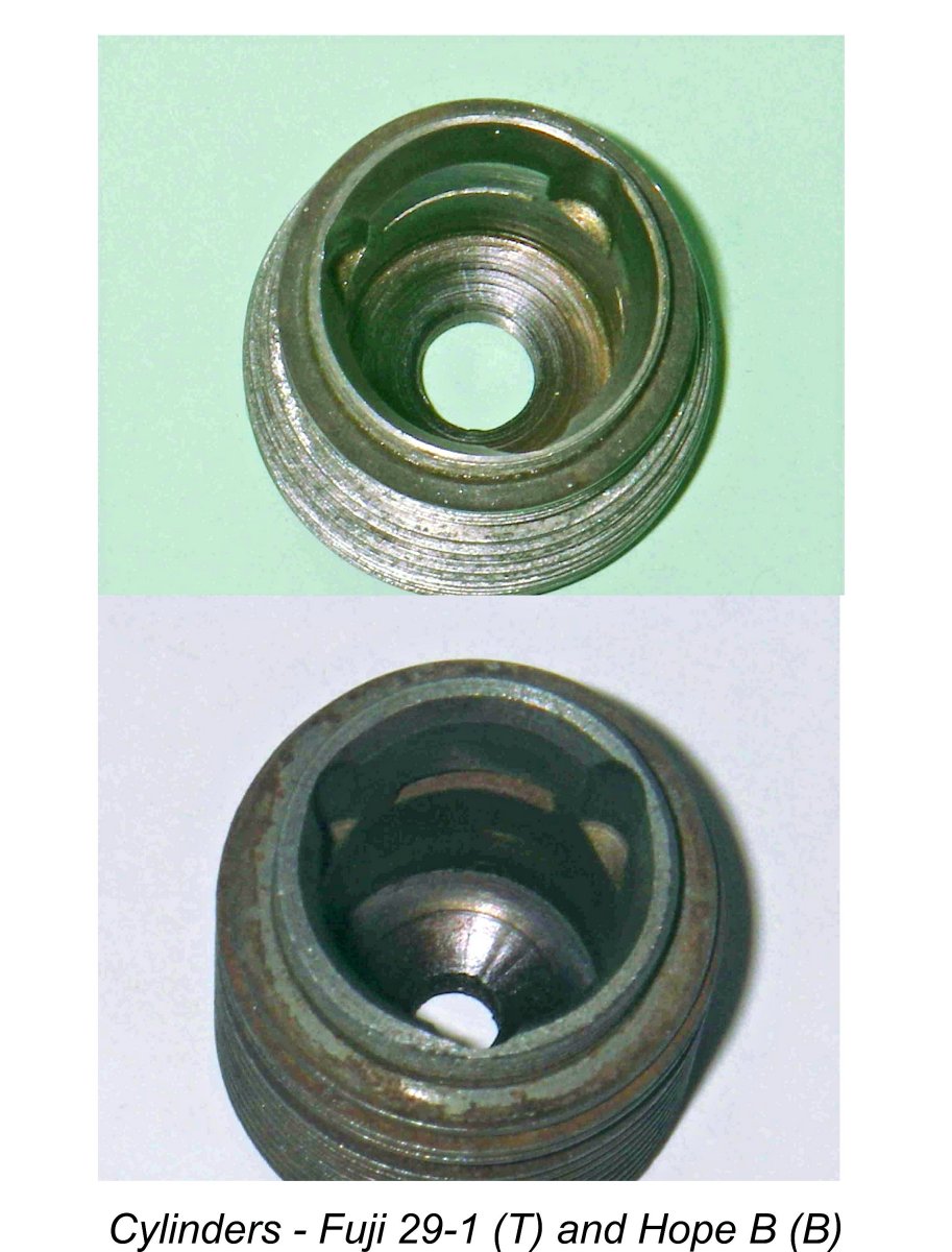 Moreover, the cylinder porting of the Fuji 29-1 with its three internal bypass flutes is a direct reflection of the Hope B, as is the blind bore with integral fins. In fact, the cylinder design is essentially identical to that of the Hope B apart from the bore. Finally, the major crankshaft design features and dimensions (apart from the stroke) appear to be common to both designs.
 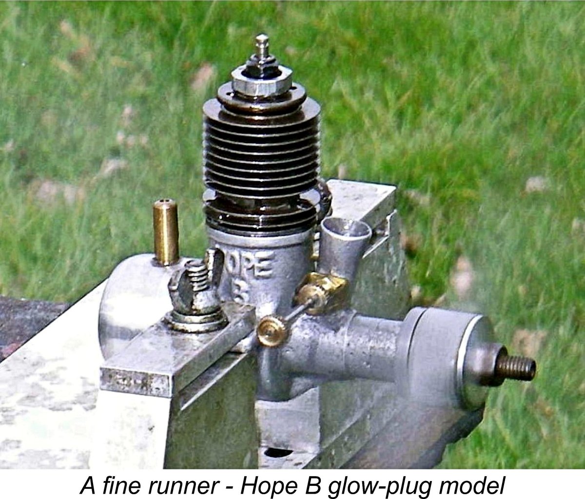 With the caveat that none of this can be proved at the present time, here’s my working hypothesis. My suspicion is that the Fuji 29-1 was the product of someone – perhaps a former associate of the Hope manufacturers - who looked hard at the Hope B and thought that he could do better. The main changes that he clearly saw as being desirable were the adoption of short-stroke internal geometry to facilitate the attainment of higher speeds, along with some improvements in the general styling of the engine. However, he saw no need to beef up the engineering design, remaining firmly in the minimalist design camp. He also retained the
 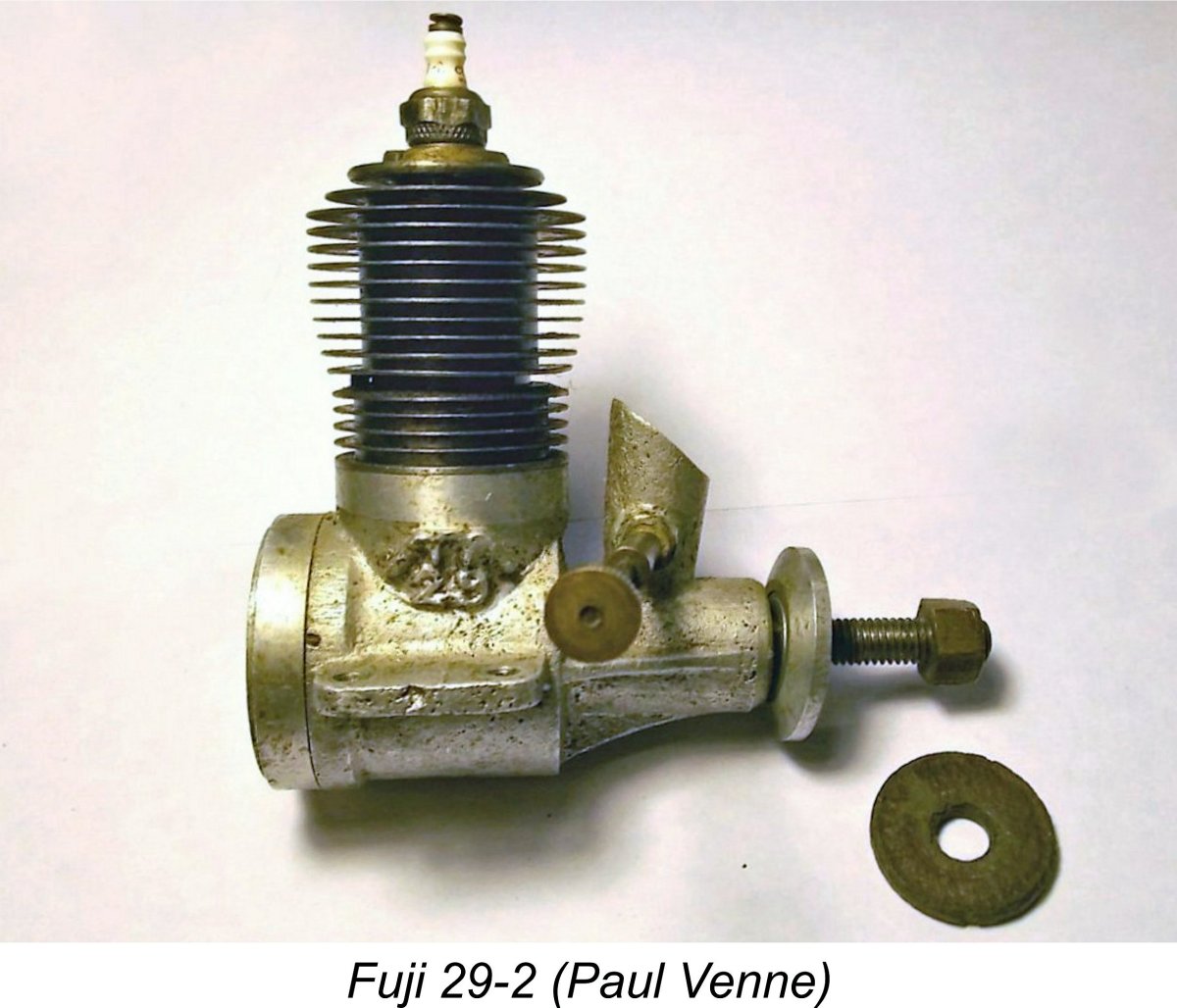 It appears that several of the problem areas mentioned above were not long in receiving some attention from the manufacturer. Reader Paul Venne has kindly provided details of what appears to be a somewhat refined version of the Fuji 29-1 model just described. Along with some gas-flow amendments, this variant displays a number of structural improvements in areas which I had identified as problematic in the original version. I have accordingly elected to designate it as the Fuji 29-2 variant of the engine.
 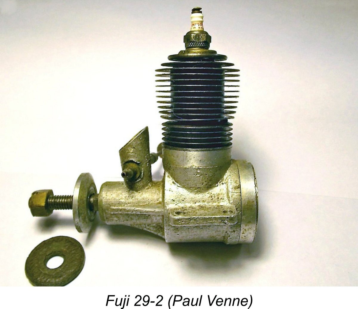 My example of the 29RV-1 variant to be discussed in the next section of this article appears to have the same cylinder as the 29-2 model now under scrutiny. This allowed for a detailed inspection of that cylinder design. Looking closely at the exhaust ports on my RV example, it becomes immediately apparent that they are shallower on the revised cylinder than they are on the original 29-1 version. The depth of the exhaust ports is only 1.5 mm as compared to the 2.0 mm depth of the earlier ports. Moreover, the pillars of metal separating the three exhaust ports are notably narrower in the revised component. The difference in overall exhaust port area is thus not as great as it might otherwise have been.
 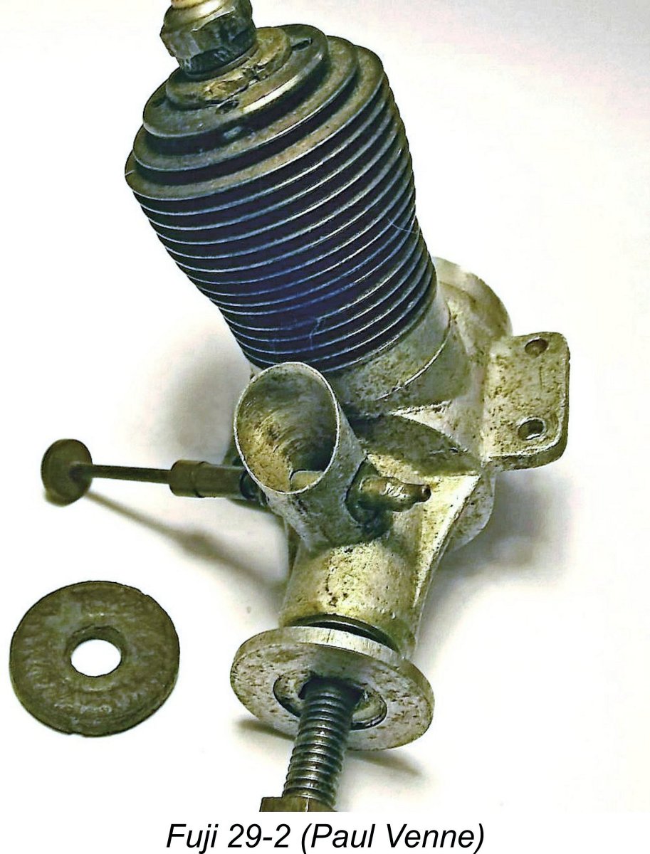 This design provides an extremely generous bypass and transfer area, but it does have the downside of eliminating the possibility of providing any overlap between the exhaust and transfer ports. The top of the transfer ports as represented by the upper edge of the circumferential channel mentioned above necessarily has to be located below the bottom of the exhaust ports in order to maintain a crankcase seal. As a result, the transfer period is inherently constrained.
 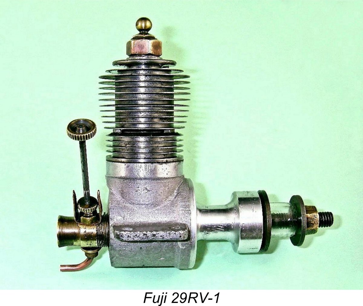 Japan's then-recent defeat in WW2 had not by any means robbed the Japanese people of their national pride - on the contrary, they were more determined than ever to seek opportunities for asserting their capabilities, in which they justifiably retained complete confidence. This doubtless goes far to explain the fact that during the late 1940’s a surprising number of Japanese model engine manufacturers developed “racing” versions of their products. These were most likely produced in relatively small numbers with the primary intention of showcasing the various manufacturers' technical capabilities to others, most notably the aeromodelling members of the Allied forces of occupation.
 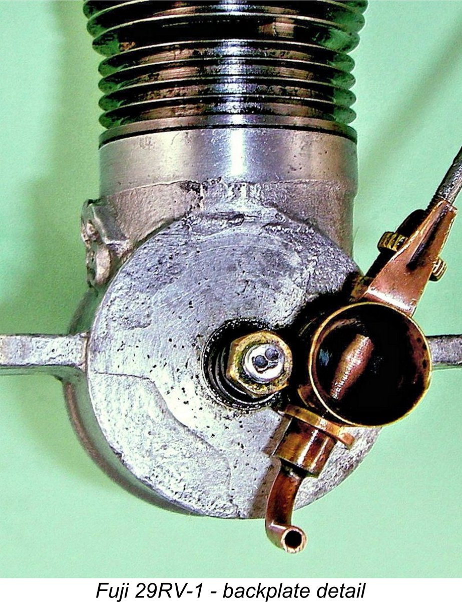 with the 29-2 FRV model. The identification cast onto the crankcase was also identical. However, the cast-on identification appeared on the opposite side of the engine. This anomaly invites an explanation.
 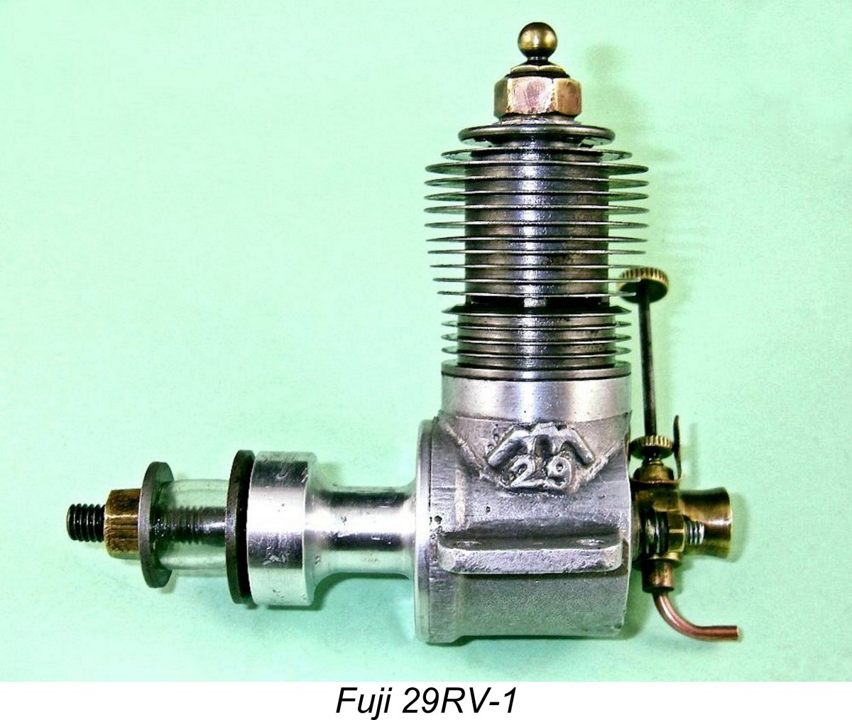 My attempts to dismantle the engine for internal examination proved even more fruitless than they had been for the FRV model - both the cylinder and main bearing housing resisted any attempt to remove them by “fair” means. One actually wonders if some form of thread-locker was used..........Given the engine’s seeming rarity and fragility, I eventually elected to leave well alone.
 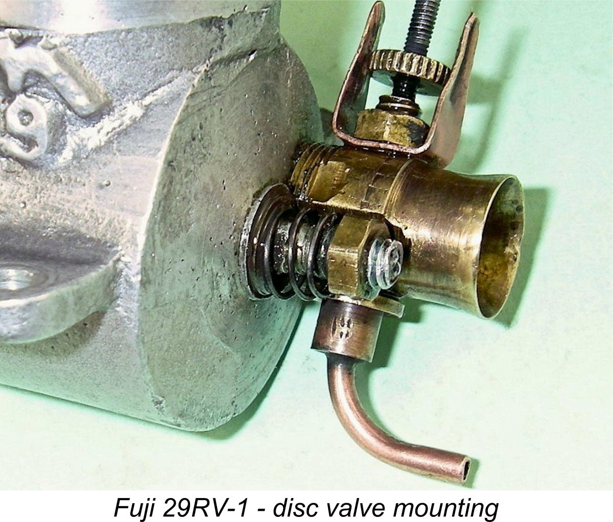 The compression ratio of the RRV version has also been raised a little, presumably through a change in the internal machining specification for the cylinder head. A
 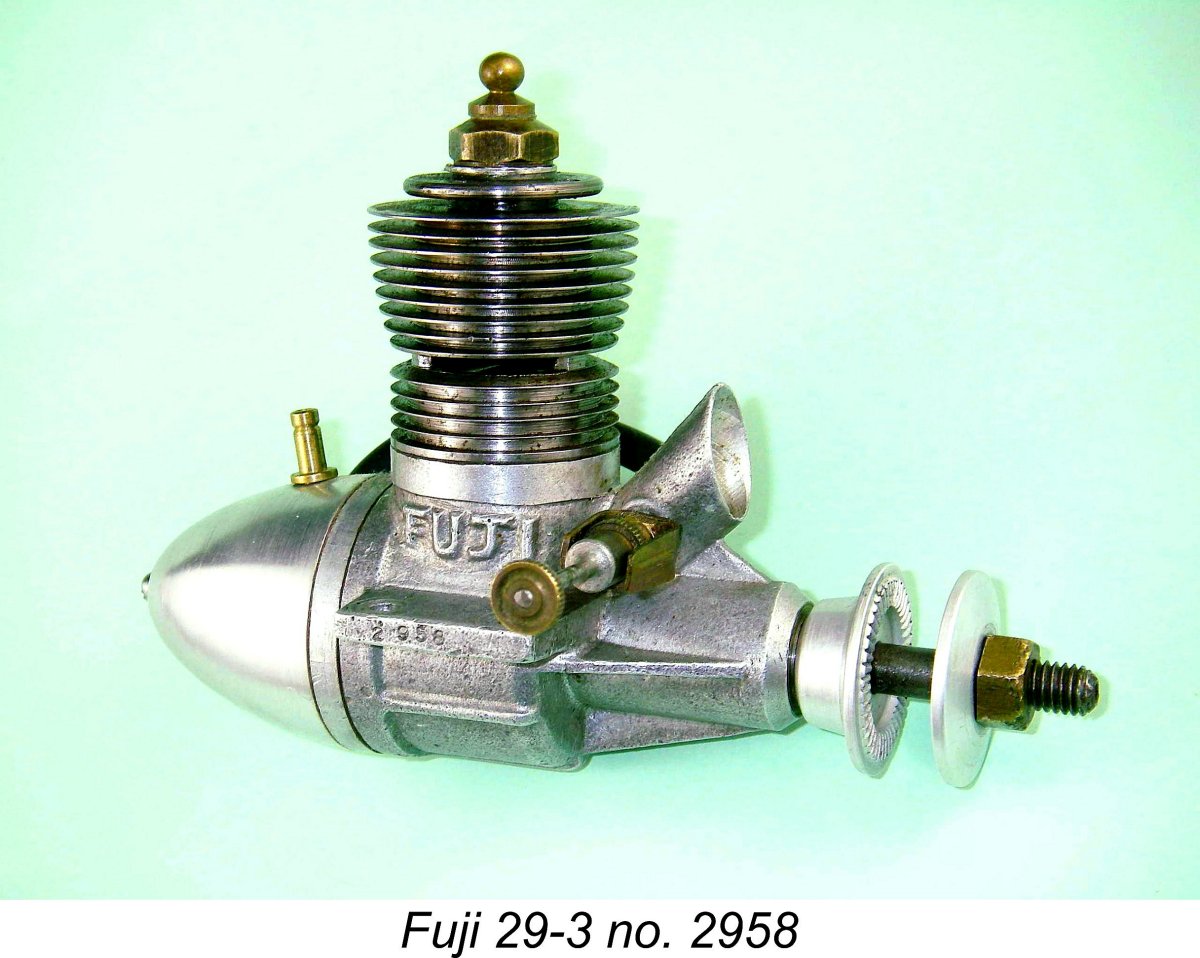 By the latter part of 1949 the Fuji company was sufficiently well established that it felt able to take steps both to “clean up” its existing products and expand the range. One tangible result of this was the late 1949 appearance of a somewhat more refined version of the Fuji 29 FRV model, which I have designated the Fuji 29-3 variant. Another was the almost simultaneous appearance of the first Fuji .099 cuin. model, which was illustrated earlier.
 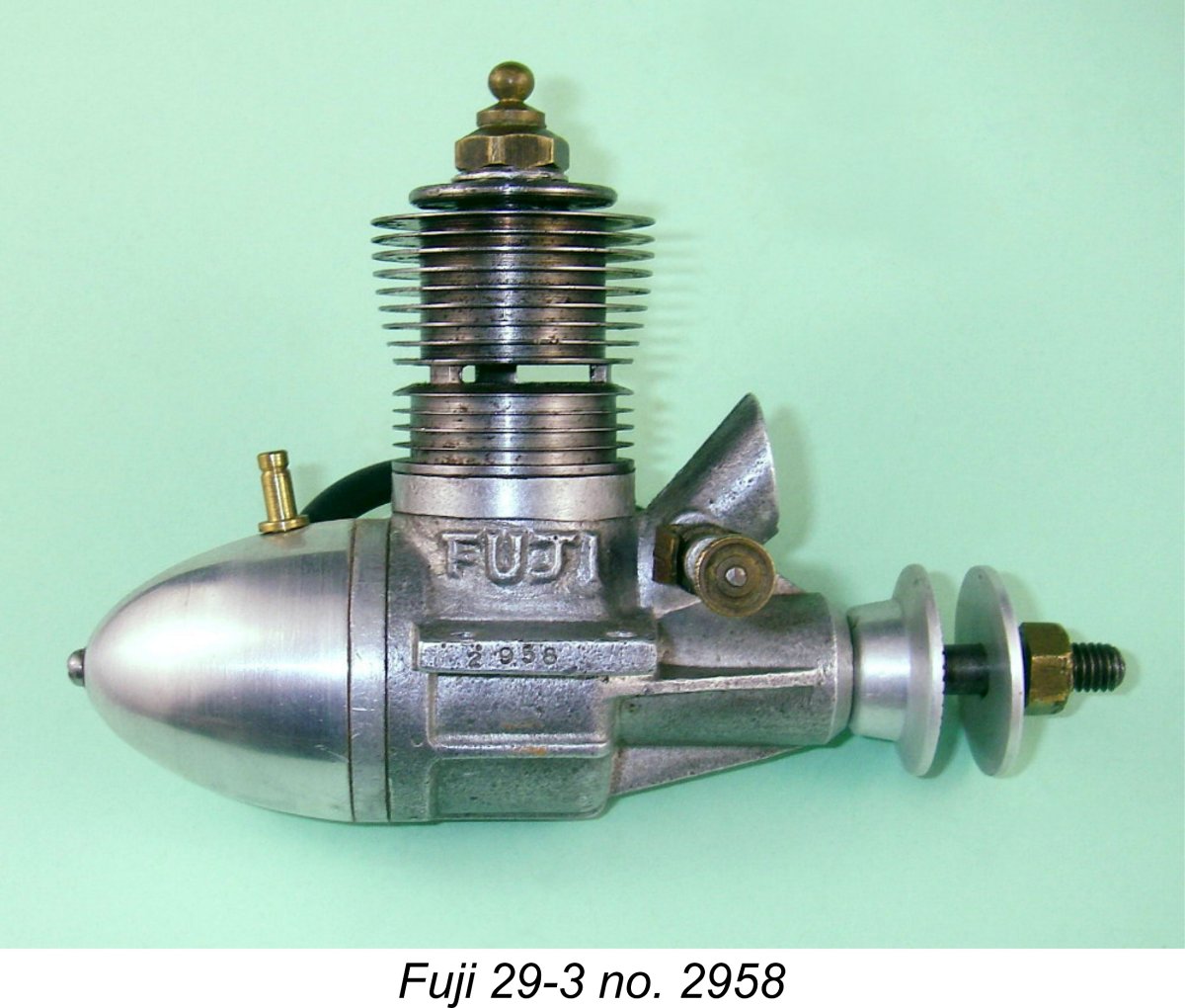 Sand-castings were still employed throughout but were now produced to significantly higher standards of quality. The revised main casting featured four substantial stiffening webs around the main bearing, while the intake venturi was now sharply raked forward, thus matching the style of the first Fuji .099 cuin. model which appeared more or less concurrently. The mounting lugs were made considerably thicker and hence stronger, while axially-oriented stiffening webs now appeared on the crankcase beneath the mounting lugs and at the bottom of the case.
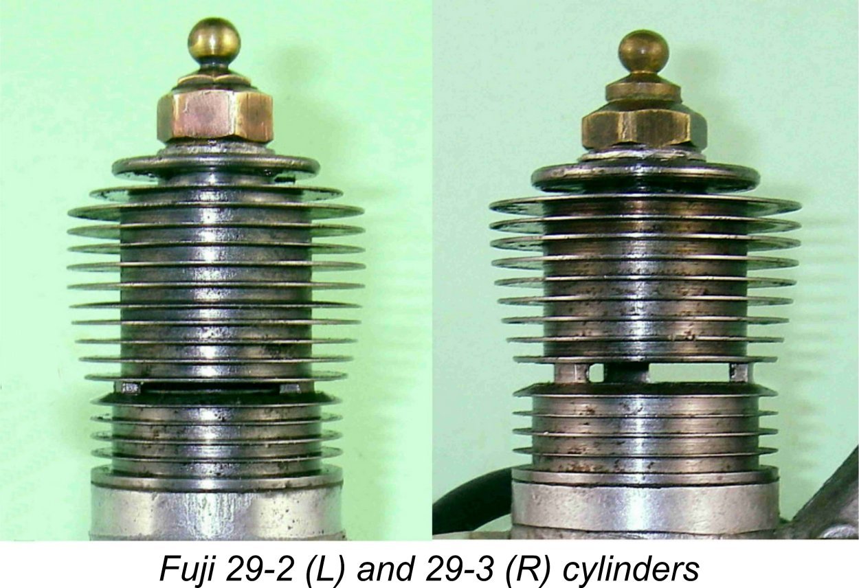
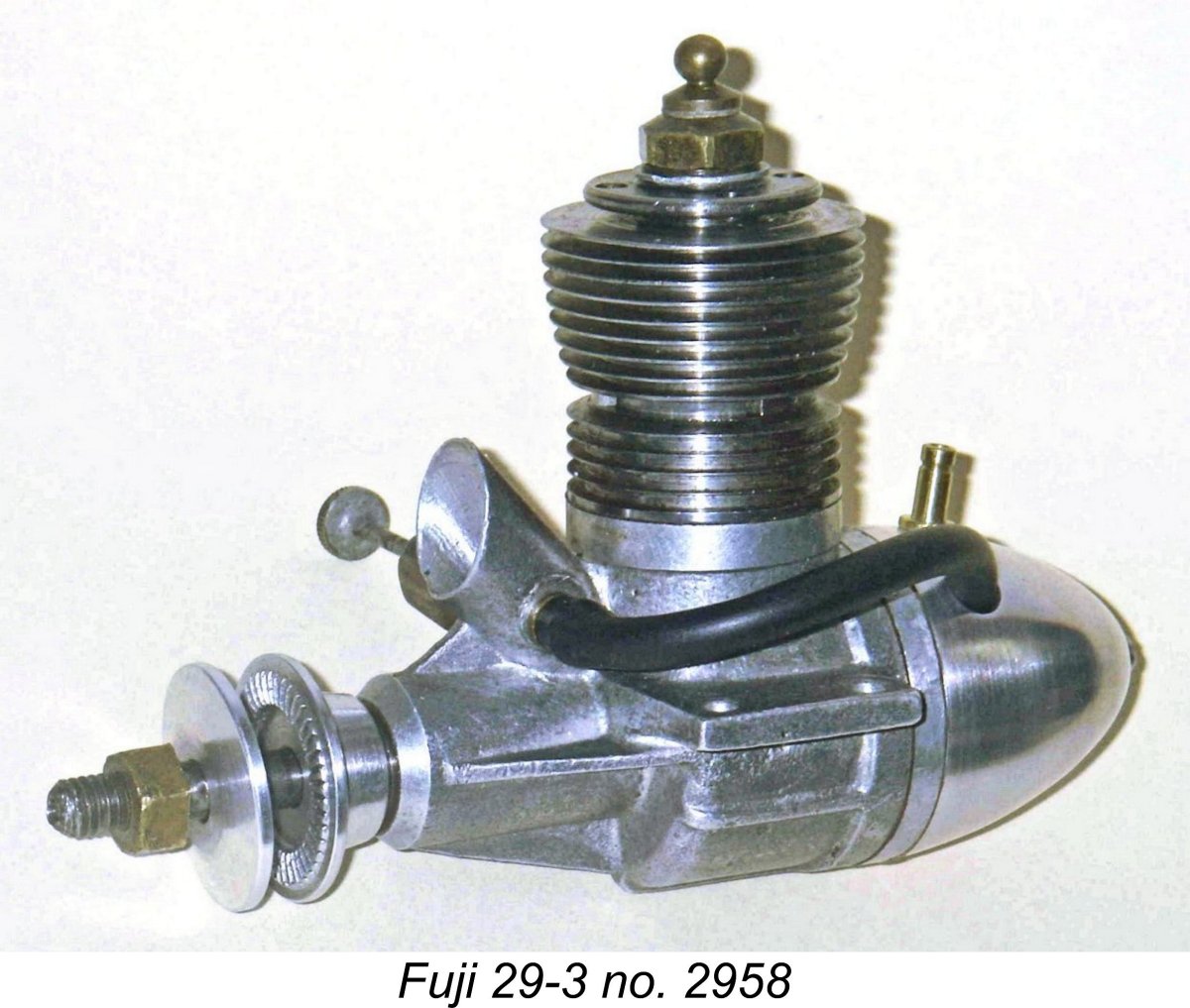
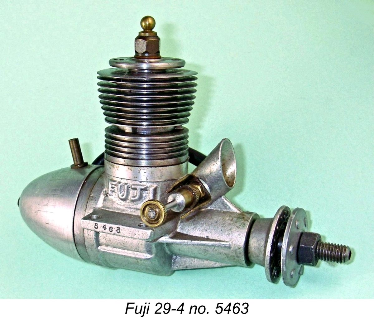 We need not spend much time discussing this next variant, since it was identical to its predecessor in all respects with the exception of the glow-plug thread. This was now changed to the ¼-32 thread which had rapidly become the standard worldwide. This change appears to have been made in around mid 1950.
 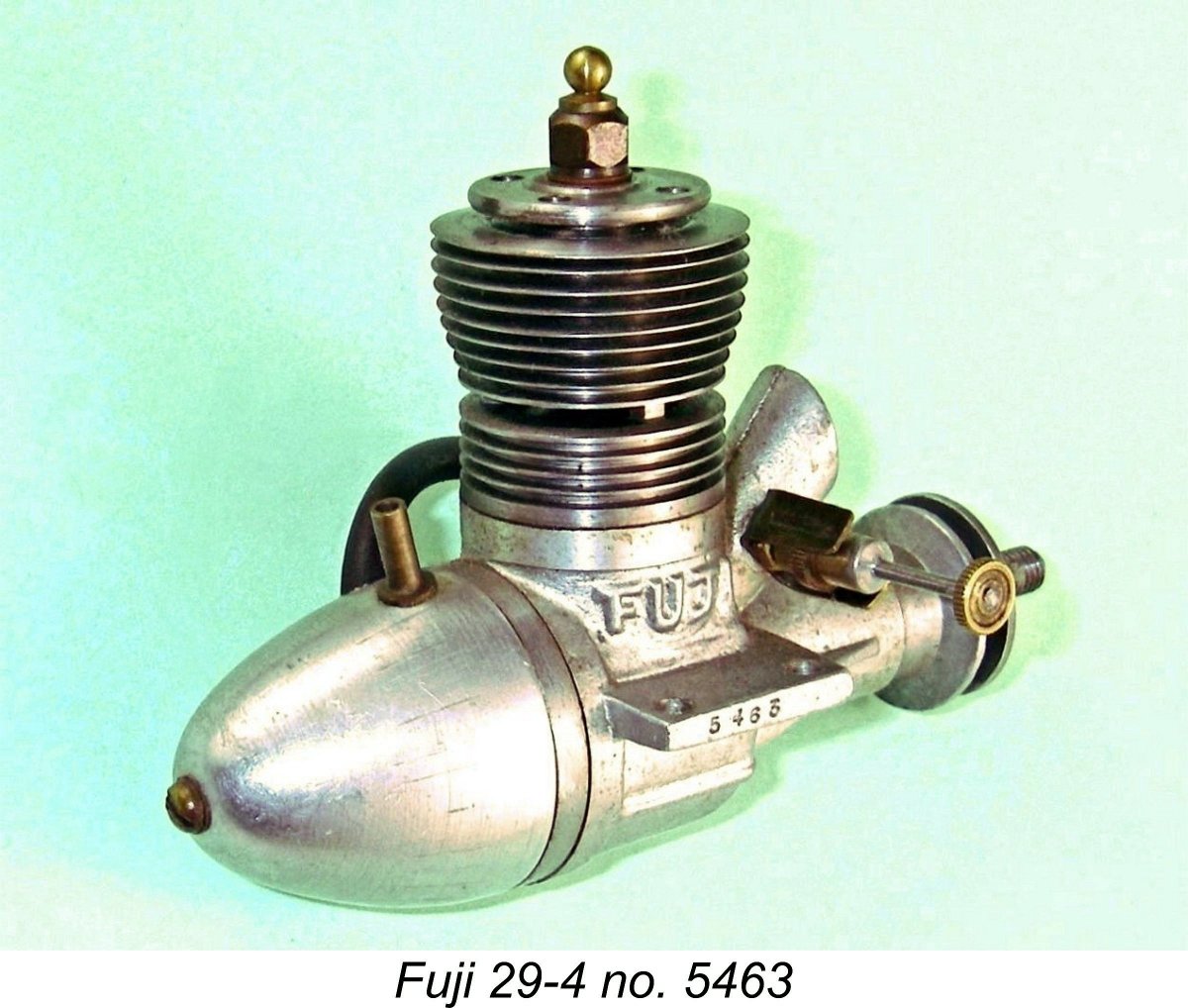 months of production. This total included the 29-1 and 29-2 models which bore no serial numbers. Quite an impressive total considering that they were also making the companion .099 model in comparable numbers throughout much of the same period. Clearly production capacity had been significantly ramped up!
 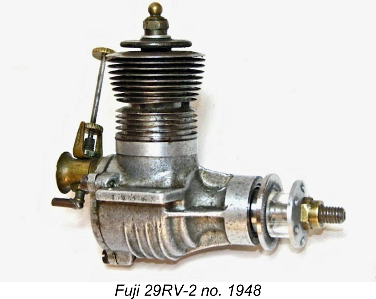 At around the time when they were revising the Fuji 29 to accommodate a ¼-32 glow-plug, producing the 29-4 model just described, Fuji seem to have decided that there was still a sufficient market for a somewhat higher-performance version of their 29 model to justify the development of a revised version of their earlier 29RV-1 model. This led to the release of a comprehensively reconfigured version of the “racing” 29RV-1 design which had first appeared in 1949. In all probability this took place in mid 1950, more or less coincident with the introduction of the companion 29-4 FRV model already described.
 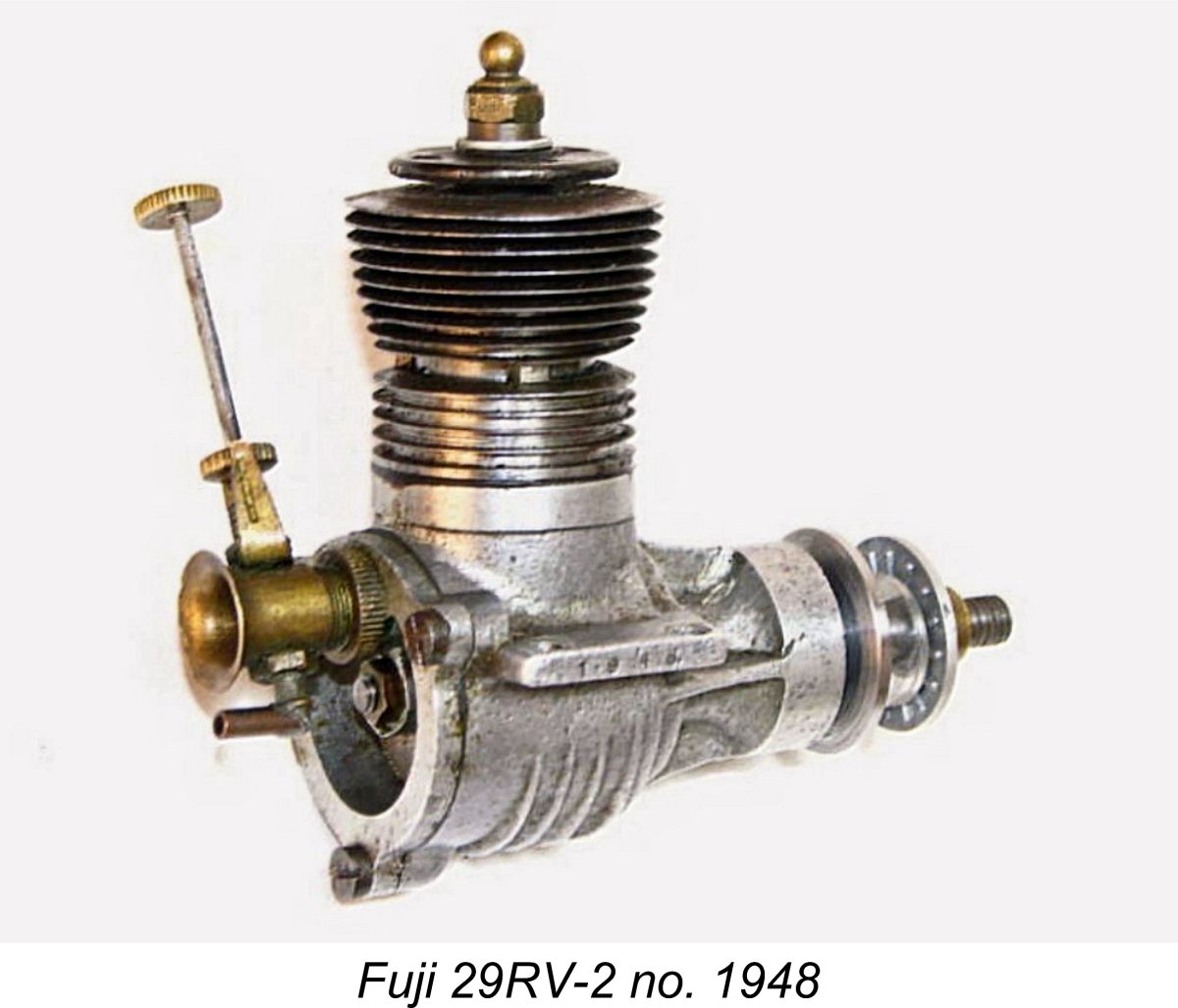 The disc valve was now of steel, which is a far superior choice of material to the aluminium alloy used in the 29RV-1 version. The spring tensioning arrangement seen on the disc valve spindle of the earlier model was no longer featured, implying perhaps that the spindle was now fixed rather than turning with the disc as before. The screw-in carburettor unit continued to be of brass, and the same needle valve assembly remained in use. Overall, the engine presented a most striking and business-like appearance!
 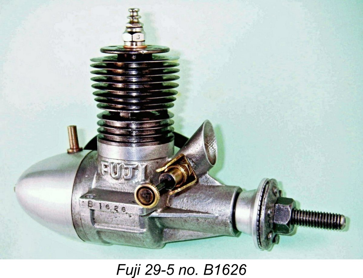 One of the Achilles’ Heels of all of the Fuji 29 models produced up to this point had been the very thin cooling fins machined into the soft and malleable cast iron cylinder. These fins were extremely prone to incidental damage, as evidenced by numerous examples of the engines which I myself have encountered.
 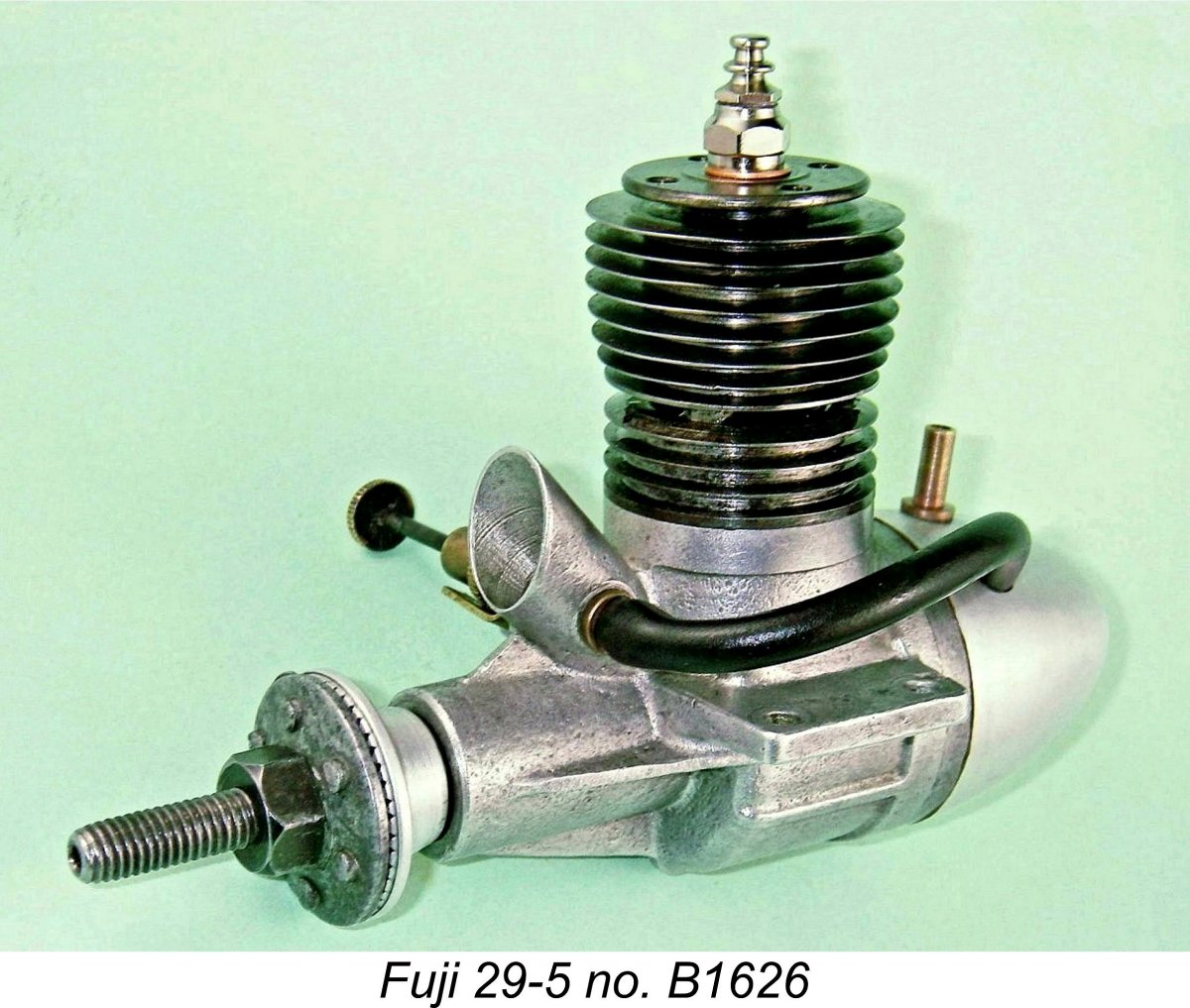 This change almost certainly coincided with the introduction of the closely-related .35 cuin. model to be described below. At this stage, the .099 models had an A prefix, the .29 models were assigned a B prefix and the newly-introduced .35 model (see below) carried a C prefix.
 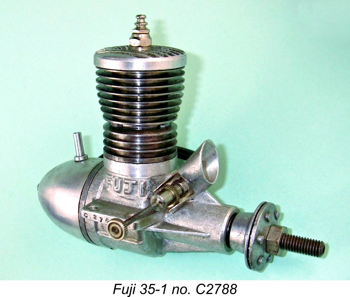 By early 1952, Fuji were clearly thinking very seriously about further expanding their range. They were already engaged in a process of updating their
 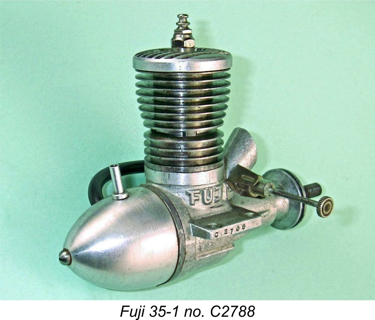 The new model was constructed around the same sandcast case which remained in use on the 29-5 model. Like its smaller predecessor, it featured front rotary valve (FRV) induction and a screw-in cast iron cylinder having integral fins and a blind bore. However, the new model sported a separate alloy head, in keeping with the trend already established with Fuji’s contemporary 099-3 model described elsewhere. This head was a dummy, serving no functional purpose other than perhaps to act as a heat sink. Like the heads of its .19 and .099 cuin. companions in the range, it was simply swaged in place on a boss into which the glow plug was threaded.
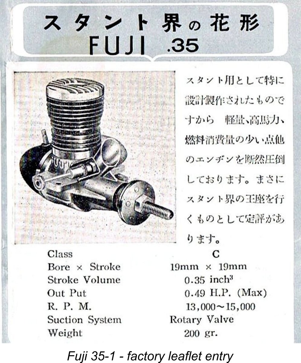
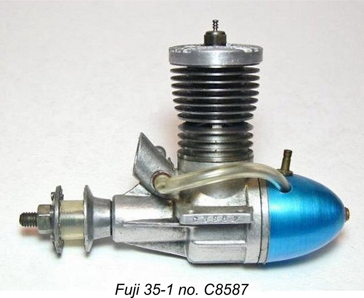
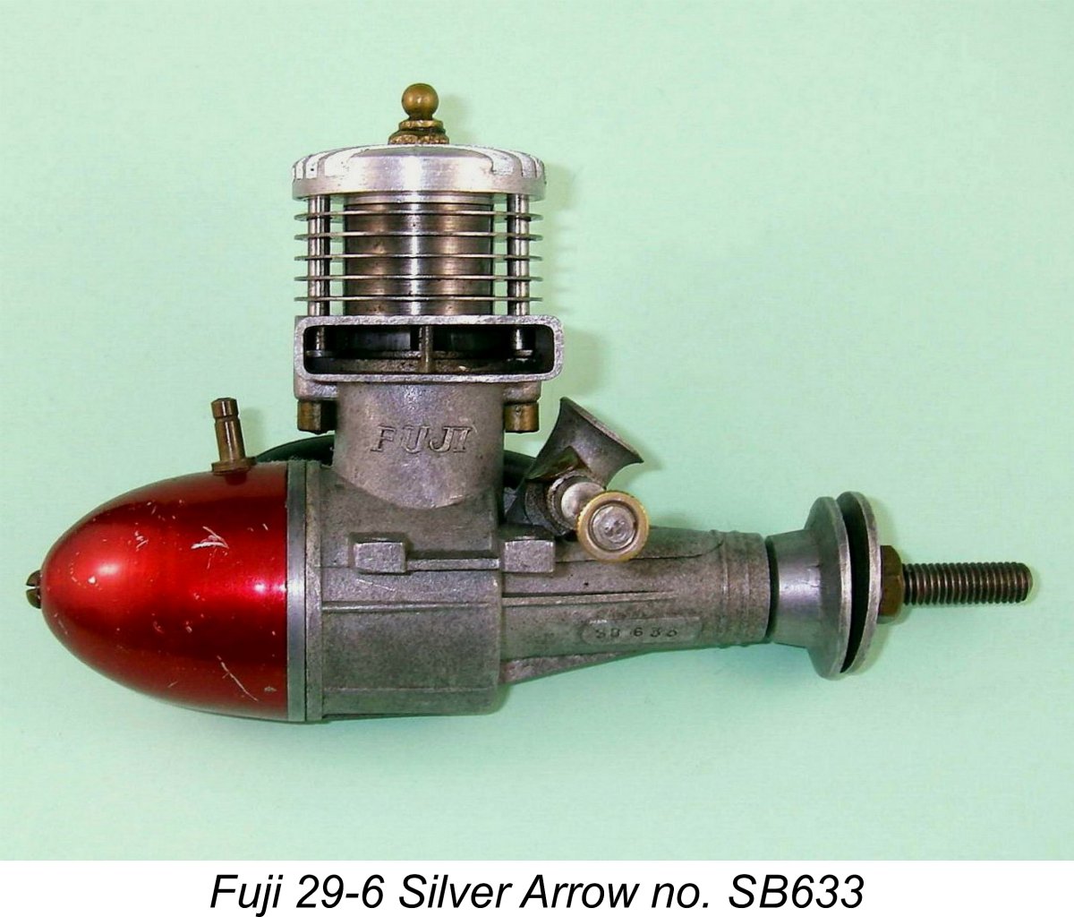 So they began to experiment with the application of the more widely-accepted cross-flow loop scavenging, using their 29 model as their “test bed”. But this wasn’t all that was about to change! By the middle of 1952 the Fuji company was sufficiently well-established that its long-term future in the model engine business seemed assured provided that it could become established in the international marketplace. Apart from the model engines themselves, the company was now a major producer of glow-plugs which were supplied with all Fuji engines and were also to be found in use in many Japanese engines other than those made by Fuji.
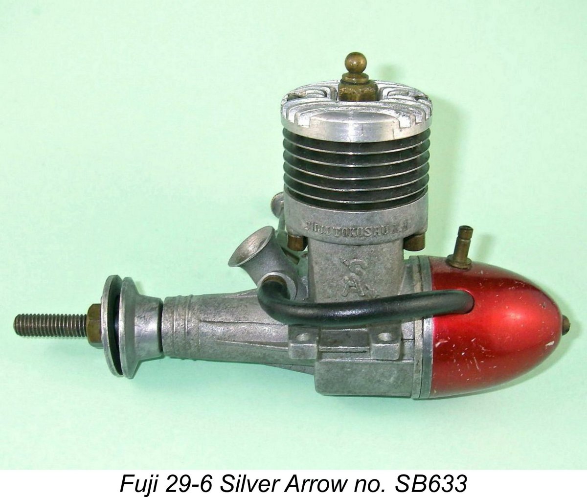
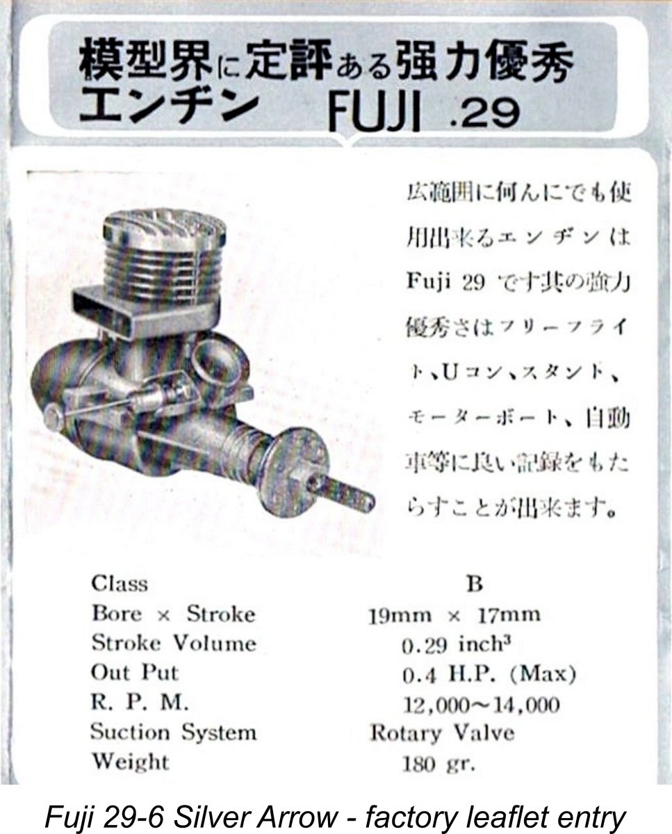 Bore and stroke were unchanged from the previous designs at 19 mm and 17 mm respectively for an identical displacement of 4.82 cc (.294 cu. in.). The new model weighed in at a checked 190 gm (6.70 oz.) with tank and fuel tubing - a little less than the Fuji 29 FRV models described earlier, but a little more than the 180 gm cited by the manufacturer. Possibly the factory weight claim related to the engine alone minus plug, as illustrated in the relevant leaflet. Claimed output was 0.40 BHP - a perfectly credible figure, it must be said.
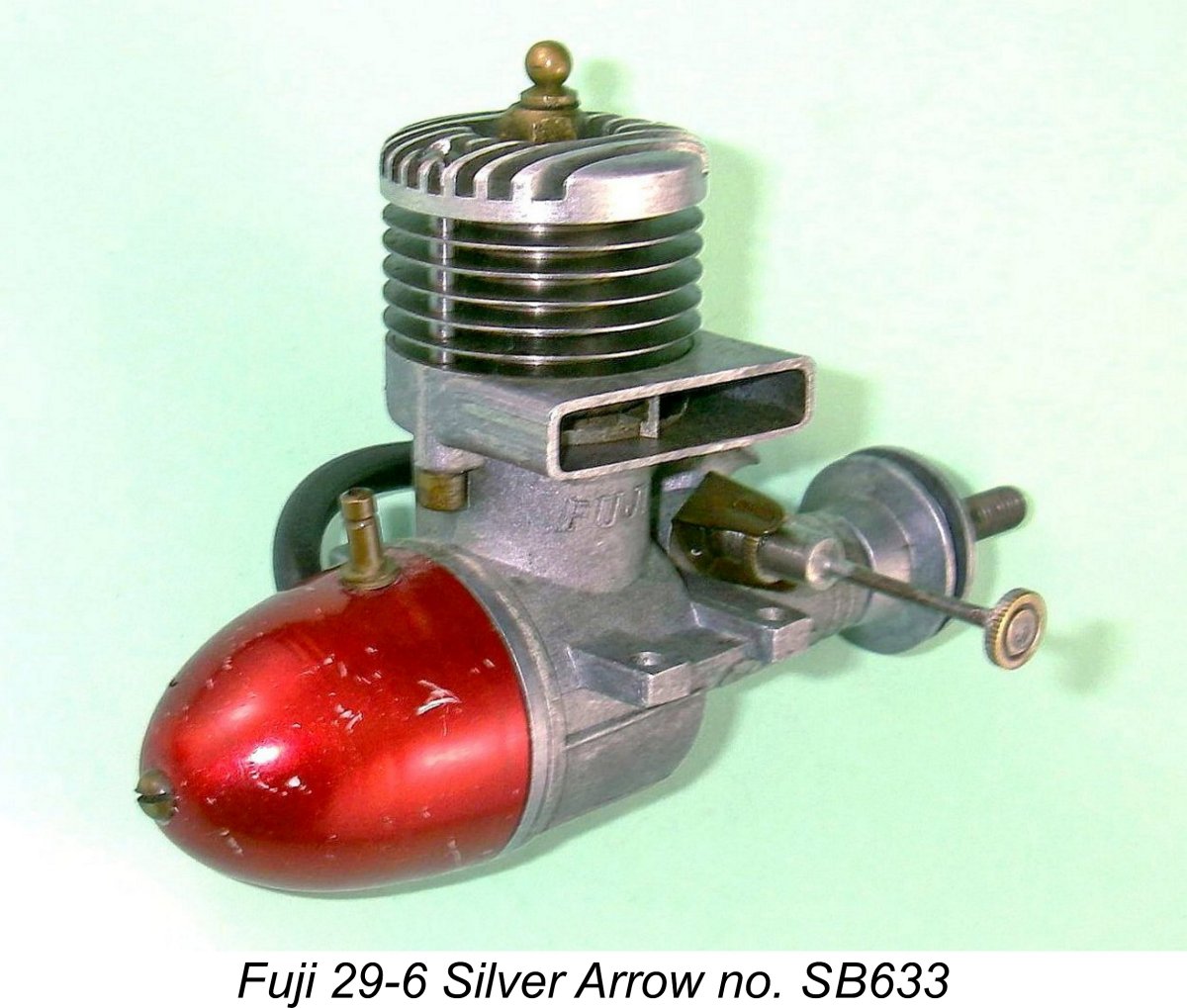
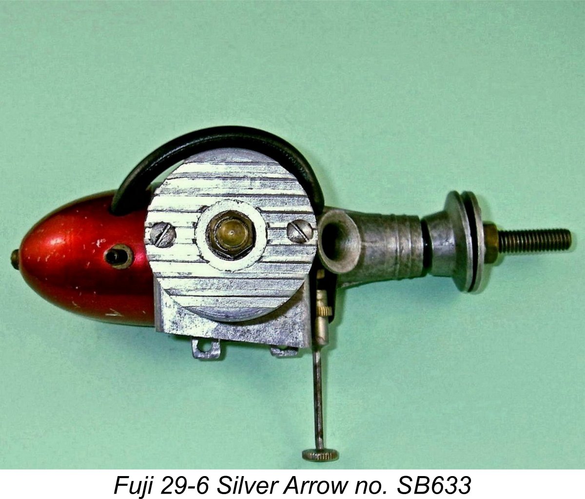 passed through the head into holes drilled through the cylinder fins below. These two long screws passed right through the cylinder fins and on through the cylinder hold-down lugs which were cast into the case. Correct cylinder alignment was thus assured, and the dummy cylinder head was held very securely by the two screws.
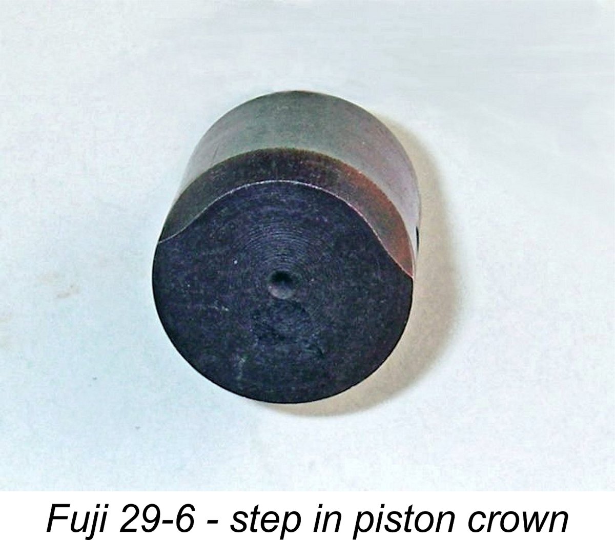
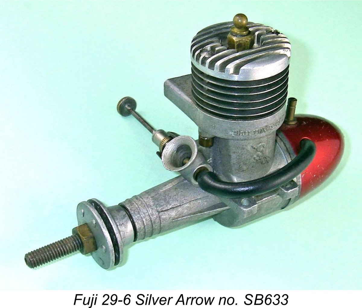
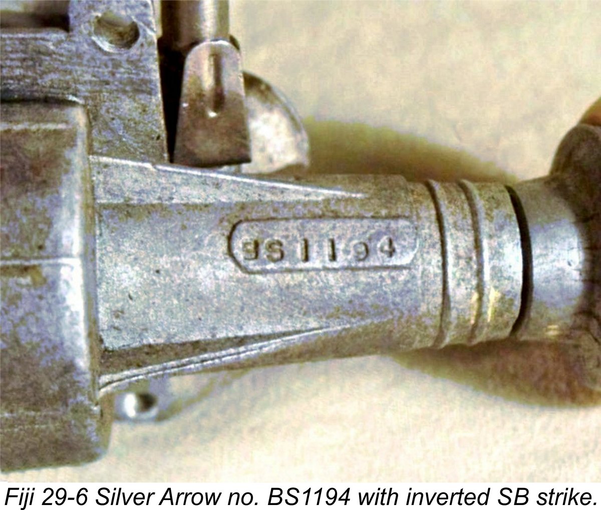
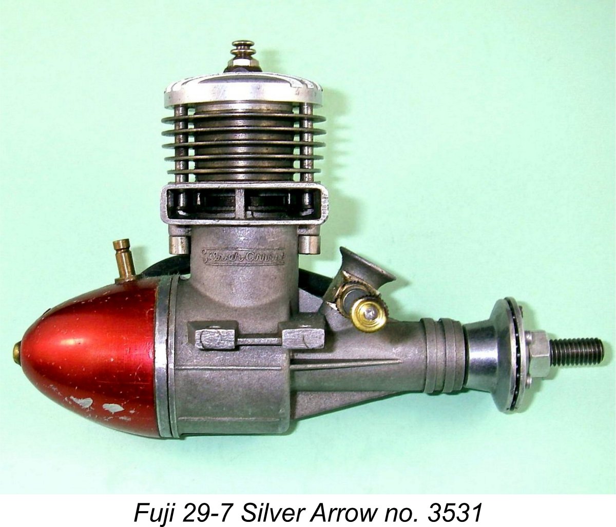 It appears that fairly soon after the introduction of this model (most likely in early to mid 1953) the crankcase die was modified. The four-piece die used initially was replaced by a conventional two-piece die having a vertical split. The intake venturi stack was moved forward a little in the revised casting, presumably necessitating a relocation of the intake port in the crankshaft to match. The bore of the intake venturi was also slightly decreased, most likely to improve suction and needle response.
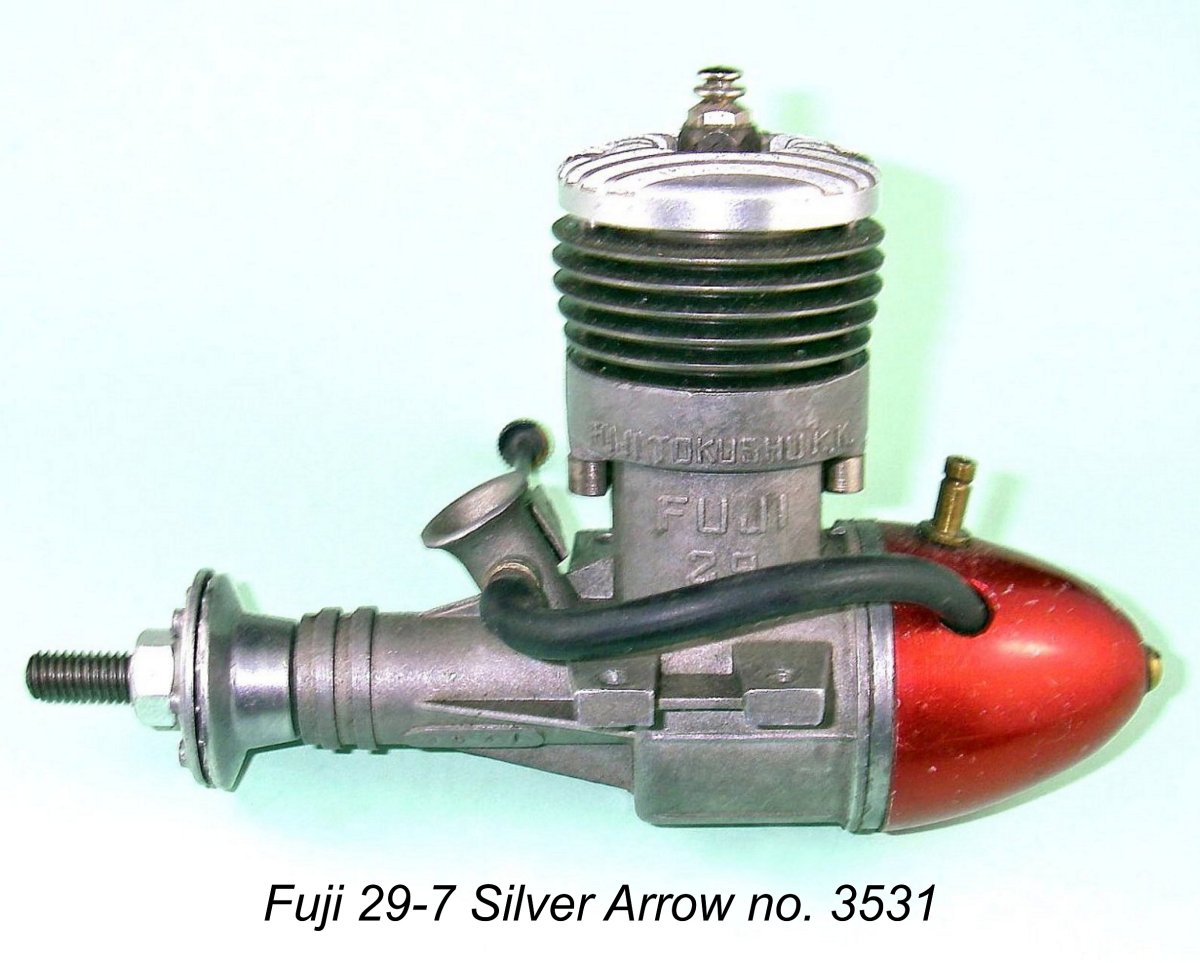
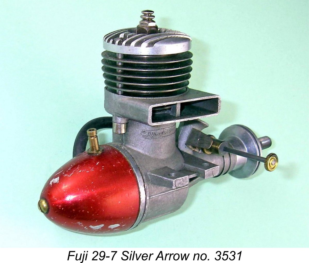 Fuji themselves appear to have agreed with this assessment, since the serial number sequence was re-configured in conjunction with the introduction of the changes summarized above. The former “BS” prefix was dropped and a straight number was used instead. The number now appeared in a raised area cast into the opposite (left) side of the main bearing. Otherwise, the rest of the engine remained unaltered. As far as is known, all of these second variants featured red-anodized tanks.
 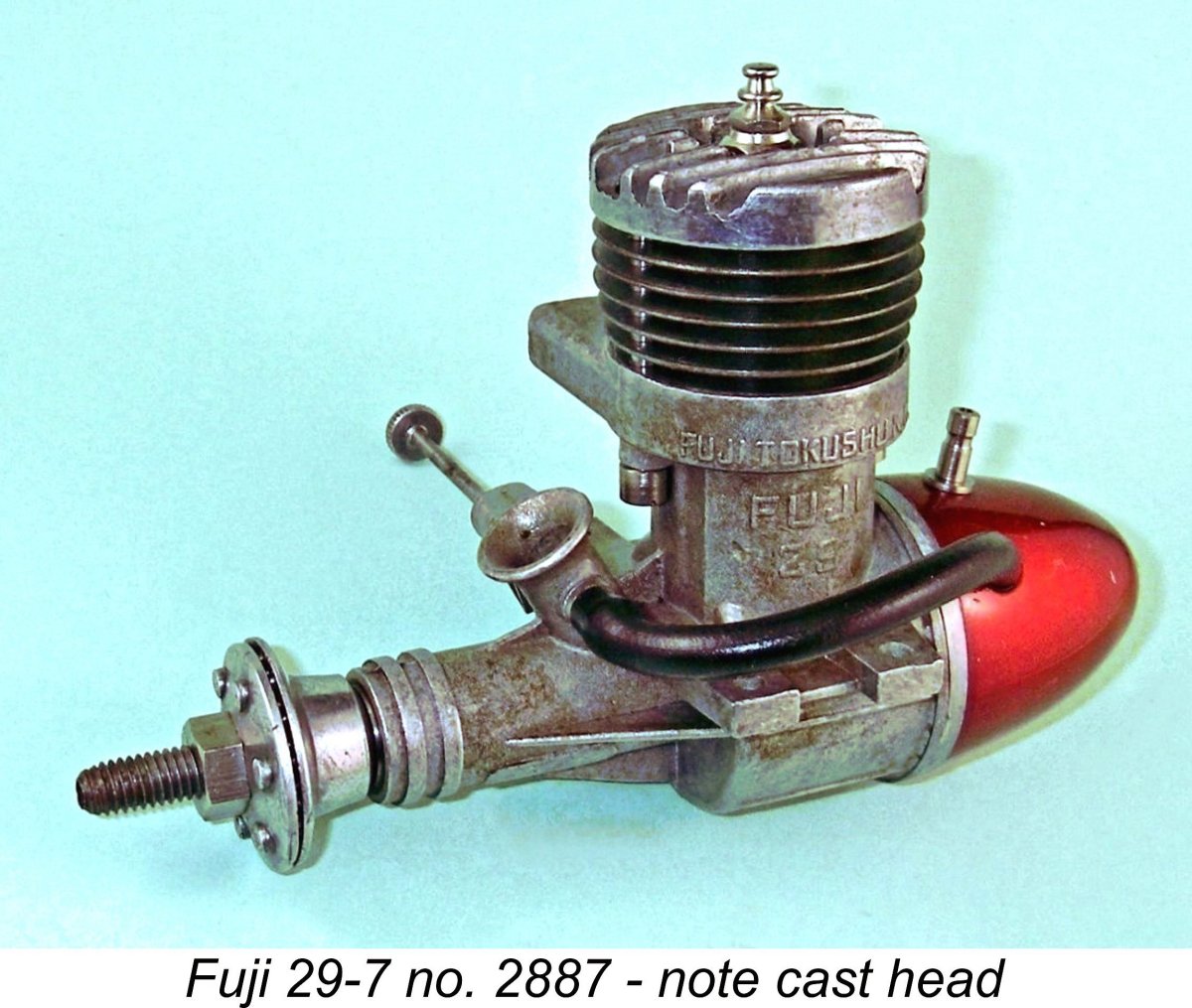 At some relatively early stage in the production life of this variant (certainly prior to the manufacture of illustrated engine number 2887), a further minor production change was made in the form of a switch from the original machined alloy cylinder head to a die-cast item having significantly deeper cooling fins. Otherwise, there were no further modifications. It's interesting to note that the former machined head continued to appear on some examples for some time thereafter, presumably to use up existing stocks of the earlier component. My own engine number 3531 is an example.
 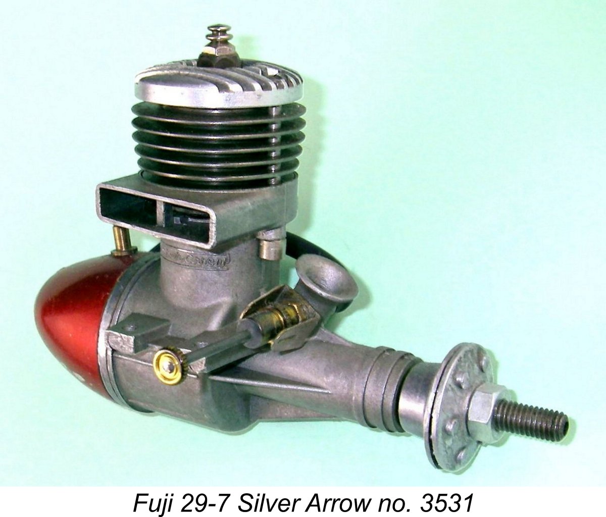 Suffice it to say for the present that the change in corporate identities also gave rise to a change in the boxes in which these engines were sold. Up to this point, all Fuji engines had been sold in a relatively small box with labels in blue, red or orange having a small circular trade-mark in evidence as required by Japanese corporate law for any product of a “K.K.” company. The familiar “winged” Fuji emblem was also much in evidence.
 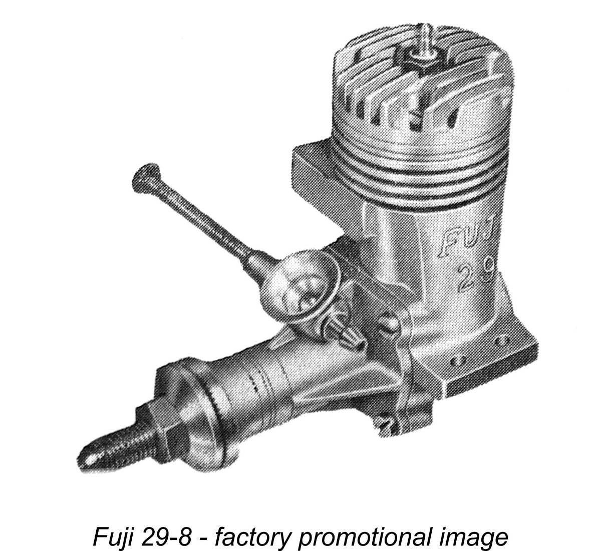 However, all this came to an end in mid to late 1955 with the replacement of the Silver Arrow by a completely revised design of more or less conventional construction. The revised Fuji 29 model (Model 29-8) which replaced the Silver Arrow was an unremarkable loop-scavenged model showing strong Enya influence.
 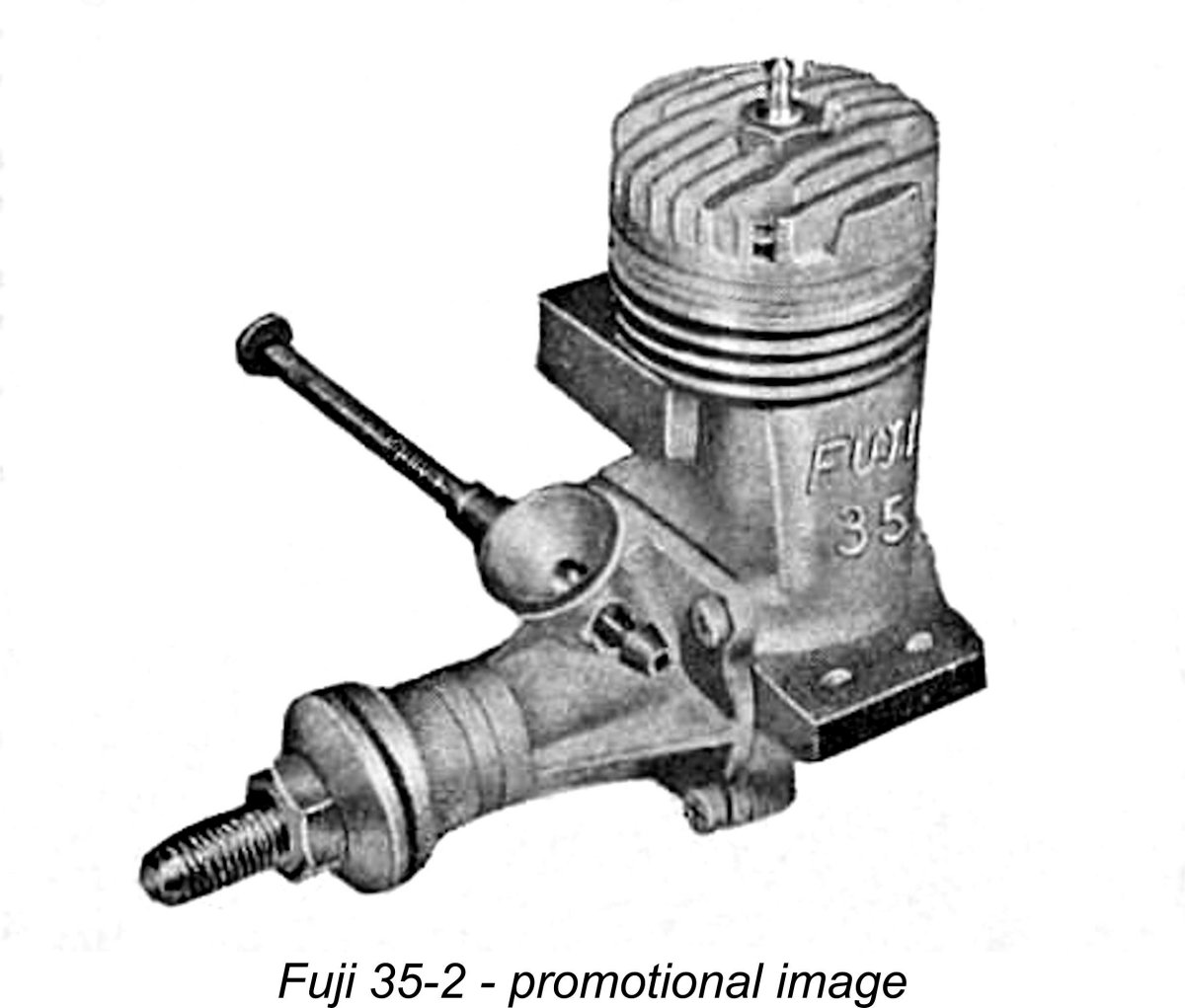 Concurrently with the introduction of their first conventional .29 cuin. model, Fuji evidently decided that it would make sense to standardize the designs of their 29 and 35 models to the extent possible. In any case, their radially-ported 35-1 model had now been in production for three years and was beginning to look quite antiquated both in design and appearance. An update was certainly in order.
 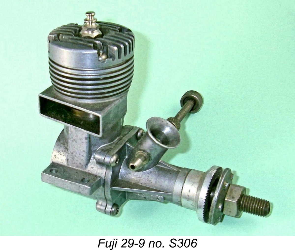 We have the evidence of Ron Warring plus Fuji's own advertising to attest to the fact that in early 1957 both the 29-8 model and its 35-2 companion were replaced by further revised designs. An example of the revised 29 model (model 29-9) bearing the serial number S306 is illustrated here for comparison with its predecessor.
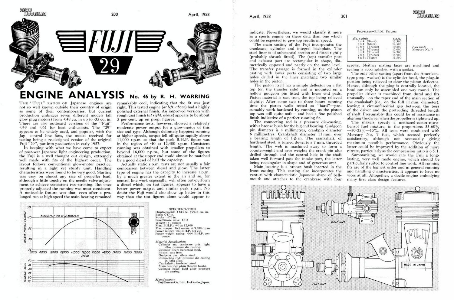
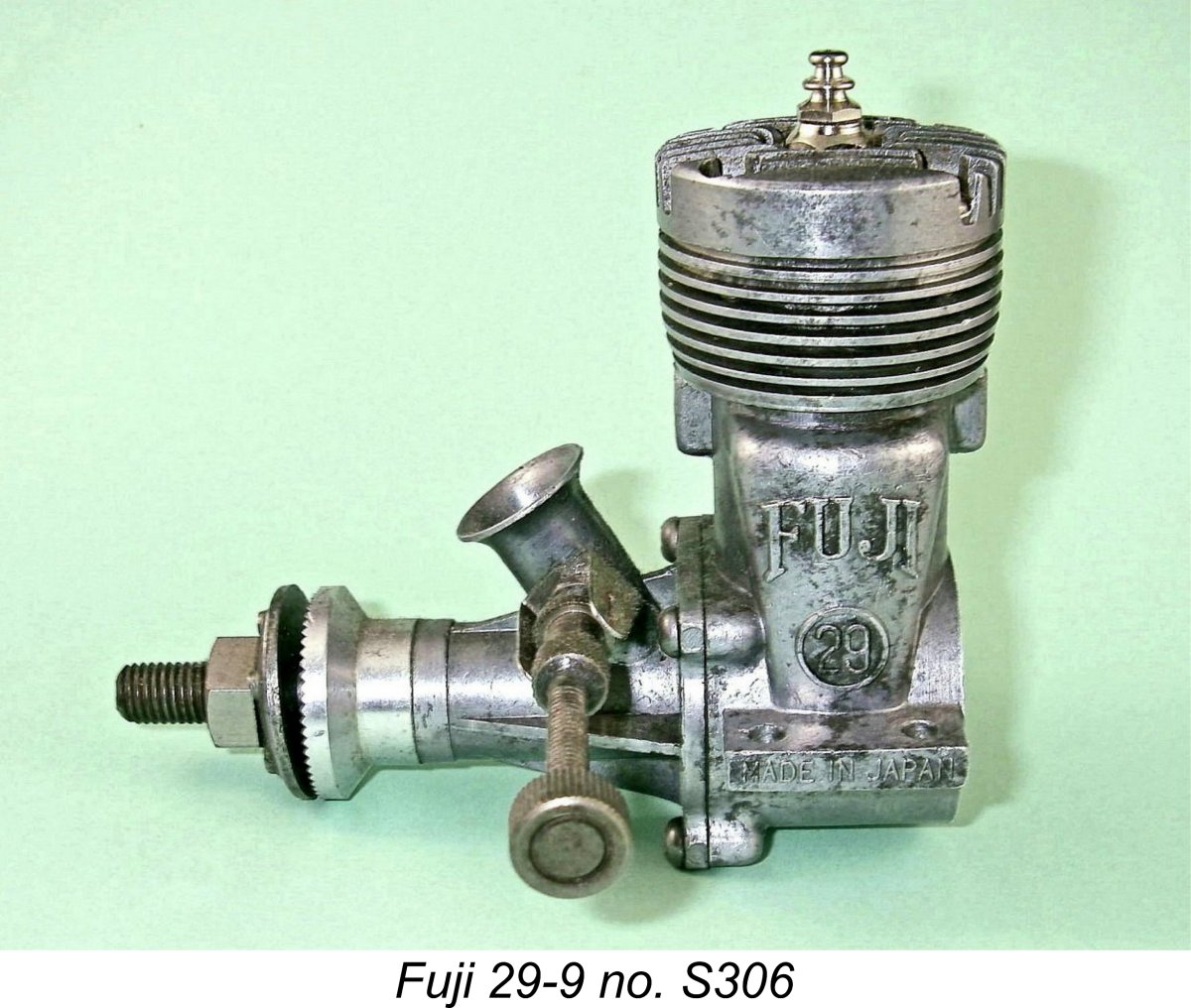
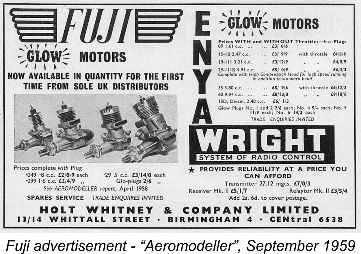 continued the Sxxxx numbering sequence without a break. But once again, as a collector and historian I feel obliged to differ - the differences in both appearance and performance are certainly sufficient that I feel it to be appropriate to recognize this as a distinct variant.
  Whenever it was introduced, the new model of the Fuji 29 represented the final step towards a complete embrace of the Enya design philosophy. There’s no way that the 29-11 model can be considered as anything other than an Enya clone. There are minor stylistic differences, of course, but all traces of Fuji’s former design independence have finally vanished without trace.
 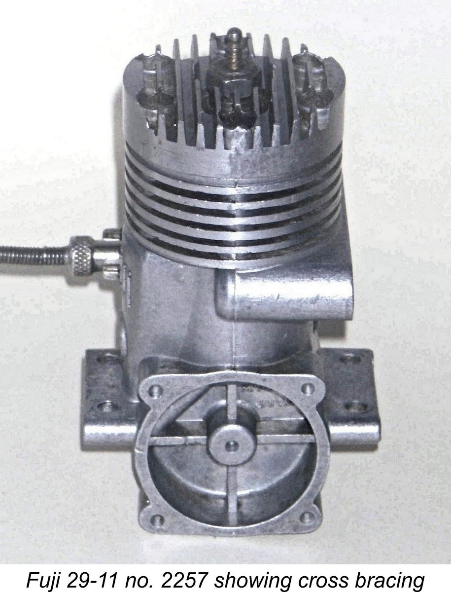 Like all contemporary Fuji products, the quality of these models was first-class. They represented excellent value for money and would have constituted a perfectly logical low-cost alternative for any modeller seeking a durable power plant for applications in which easy handling, long life and dependability rather than ultimate performance were the main objectives.
 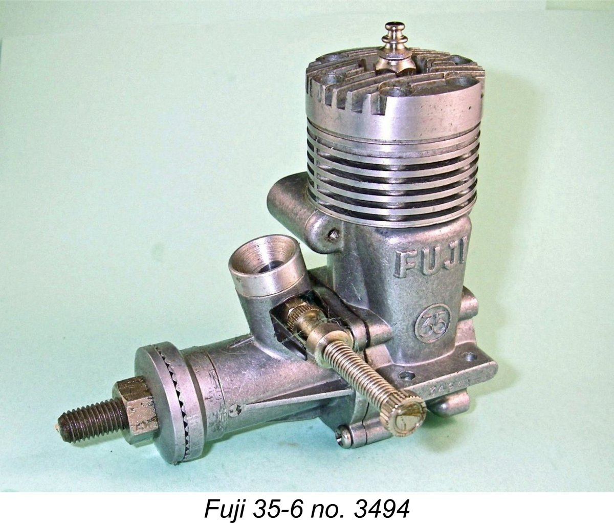 Once again, Fuji produced a slightly revised version of their .35 cuin. model exhibiting the modifications described above for the companion .29 cuin. model but otherwise remaining unchanged. As with the 29-11 and 35-5 models, the two are virtually indistinguishable apart from the slightly taller cylinder of the 35 version.
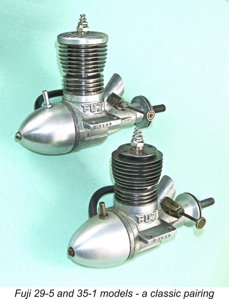
| |