
|
|
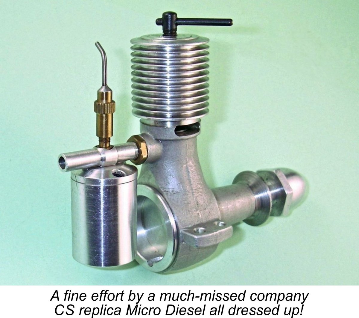
Motor City Masterpiece – the 1947 Micro-Diesel
Original examples of this very rare engine are seldom encountered today. When they do show up, they command some pretty fancy prices! To offset this situation somewhat, the late-lamented CS company of Shanghai, China produced a run of rather nice near-replicas of this engine. Although these replicas are actually themselves not all that common, the present-day enthusiast almost certainly has a far better chance of encountering one of them than of lucking into an original! The famous Swedish model engine replicator Arne Hende also arranged for the production of a limited number of replicas of this engine to his usual very high standard. However, these are about as elusive as the originals! In addition, Dave Banks of England had a small series Having acquired an example of the CS Micro Diesel replica some years ago, I had been planning at some point to do a write-up on the Micro-Diesel using my CS replica as a stand-in for the original engine – I’ve done this before, as my regular readers will be well aware. However, I learned that my Australian friend and colleague Derek Butler actually owned an original example of the Micro-Diesel which was in as-new condition. As in the case of his pristine Mills 1.3 Mk. I (of which more elsewhere), Derek very generously agreed to entrust his example to my care for a proper test of the engine as well as a comparison with the CS replica. Hence the present article. It’s really hard for me to adequately express my gratitude to Derek. Before embarking upon a description of the engine, it’s worth taking the time to set out what little is known of its history. Historical Context America is not generally thought today of as a major producer of model diesels. It appears to be a seldom-recalled fact that the country engaged in what proved to be a brief but surprisingly productive flirtation with diesels during the early post WW2 era. However, just as American diesel manufacturers were getting into their stride, Ray Arden’s introduction of the commercial miniature glow-plug in November 1947 swept all further consideration of the diesel concept off the table at that time as the glow-plug immediately took over almost completely. A very brief American diesel renaissance did take place in the mid 1950’s as a result of the very worthy efforts of McCoy and Herkimer (OK), but by and large the model diesel was consigned to the sidelines for most of the post-war period in America.
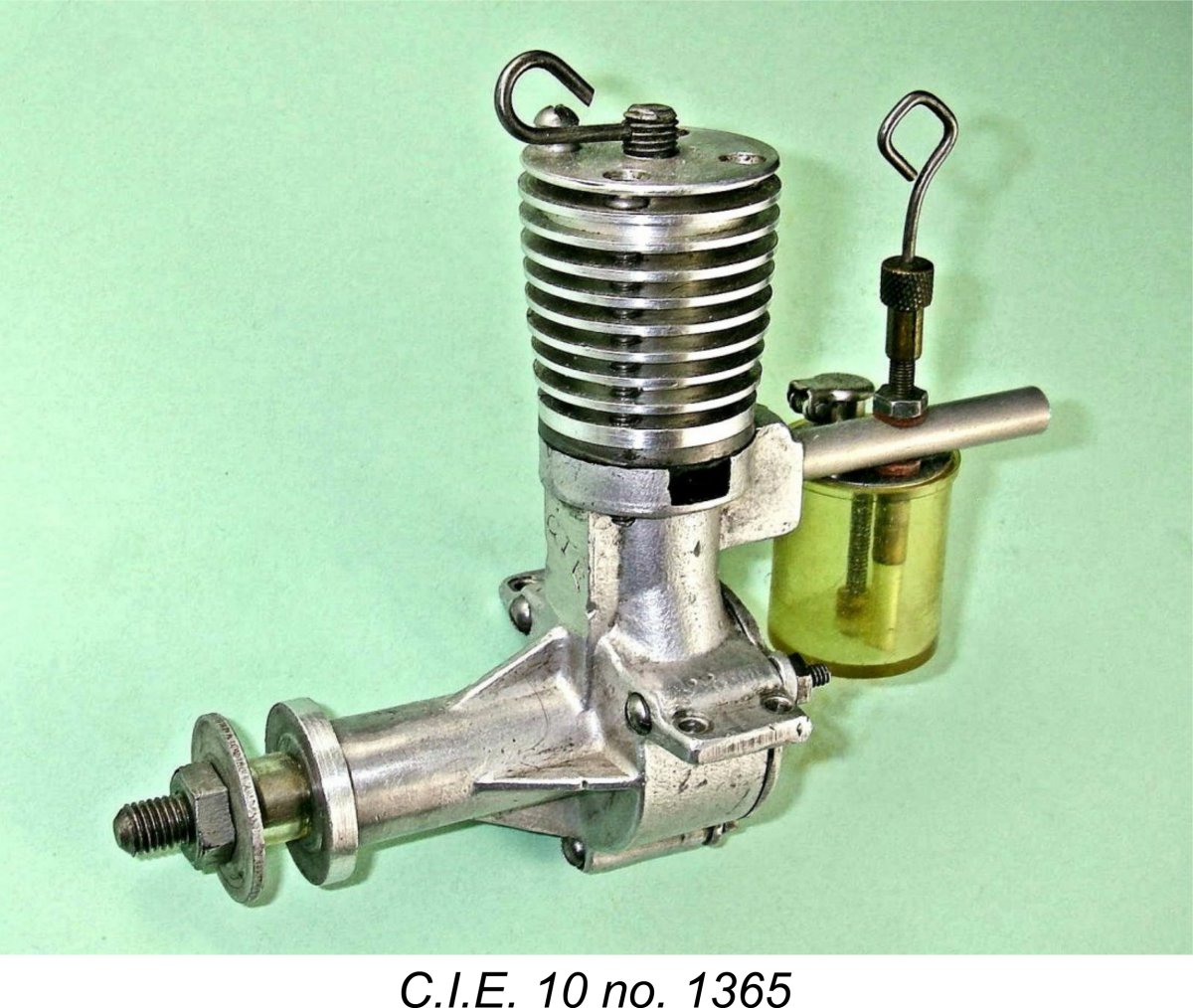
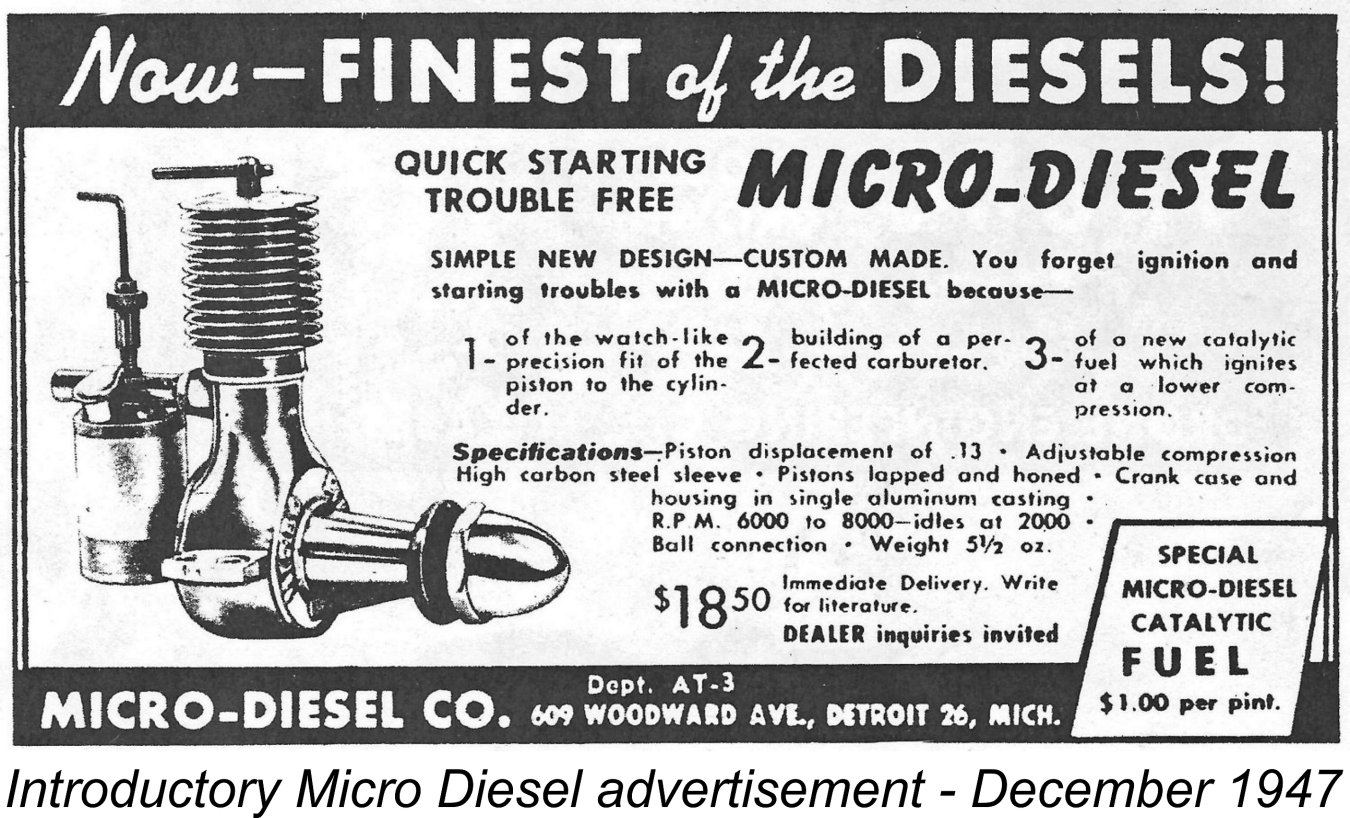
Given these facts, it comes as no surprise to find that many of the American diesels that did make it into production between 1946 and 1948 possessed considerable merit. The C.I.E., Speed Demon, Air-O, Drone, Mite and Vivell diesels may all be fairly included in this category, as may the very capably-executed D-E diesel conversions of the Arden .099 and .199 cuin. models. These engines got America off to a great start in terms of the commercial development of model diesel technology. Their chronological story is summarized in my separate article on classic American diesels. Of course, America must also shoulder responsibility for producing arguably the world’s worst-ever diesel in the form of the infamous Deezil. However, it’s important to note that the early examples of this deservedly much-maligned unit were highly serviceable engines which ran very well, as my own tests on There were other North American designs which reached the prototype stage but never made it into series production. These included the Thermite, AHC, Ken, DeLong, EDCO, Queen Bee and Strato diesel prototypes (the latter two in Canada), all of which undoubtedly reached the prototype testing stage. During this period the number of North American firms actively engaged in model diesel development at least equalled the number of their counterparts in Britain. If the introduction of the commercial miniature glow-plug had not taken place when it did, this trend would doubtless have continued. In view of this fact, I often find myself wishing that Ray Arden had been a year or two later in perfecting and marketing the commercial miniature glow-plug – given a few more years to take root, diesels might well have gained as much acceptance in America as they did in the rest of the world, and American manufacturers might have continued to carry the diesel torch for quite a while with very positive results. The Micro-Diesel which is our main subject here was one of the late-comers in this brief but very productive period of American involvement in the development of the model diesel engine. As we shall see, it was a high-quality product which performed very well indeed. Sadly, its arrival on the scene more or less coincided with the appearance of the commercial miniature glow-plug and the consequent abandonment of model diesel technology by all but a few American modellers and manufacturers. The Micro-Diesel itself was among the casualties, surviving in production for only a relatively short period of time. The Micro-Diesel was manufactured by a company which called itself aptly enough the Micro-Diesel Co. This company gve its address as 609 Woodward Avenue, Detroit 26, Michigan, USA. A diesel engine from the Motor City – seems rather fitting! Apart from that, we know absolutely nothing about the designers and manufacturers of the Micro-Diesel. This company must not be confused with the Micro Motor Co. of Berkely, California, which had manufactured the Micro 19 and Micro 24 spark ignition models prior to America’s entry into WW2. Nor does it have any connection with the contemporary Micro engines made in Italy by E. Biraghi in 1947. The Micro-Diesel's dates of manufacture seem pretty clear. The first advertisements for the Micro Diesel appeared simultaneously in the December 1947 issues of “Air Trails” and “Model Airplane News”. Allowing for Editorial lead time, this implies that the engine must have been in existence by November 1947.
The quoted introductory price of the engine was $18.50 (about £6.72 at the exchange rate then in effect), which was actually a fairly steep price at the time for a 2.13 cc engine. It would appear from this that when the engine was developed and first marketed, the manufacturers were not yet aware of the impending glow-plug revolution which was to drive prices down to a very significant degree. The same advertisements also promoted the company’s “Catalytic” diesel fuel. Despite the very clear evidence supporting an introductory date of November 1947, the fact remains that the engine was not mentioned in the article “Diesels Grow Up” by Jack Bayha which appeared in the December 1947 issue of “Model Airplane News”. Nor was it featured in the article entitled “Model Motors for 1948” by Edward G. Ingram which appeared in the January 1948 issue of the same magazine. It seems likely that these two articles were completed and submitted by their respective authors in order to meet Editorial deadlines prior to the engine’s initial advertising appearance.
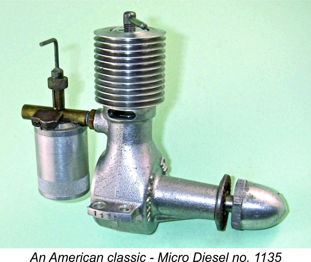
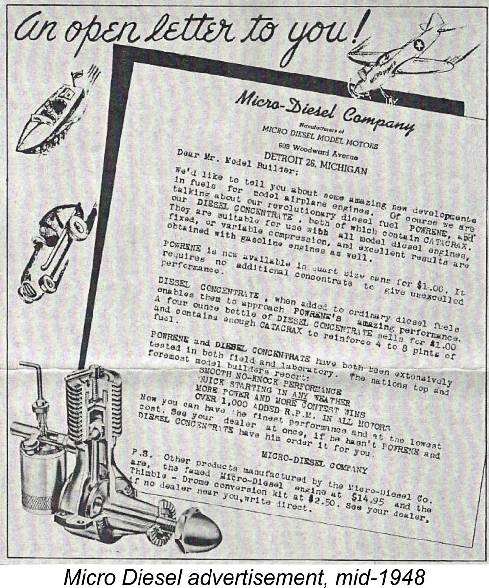
“Powrene” was a ready-to-use complete diesel fuel mixture, while “Diesel Concentrate” was some kind of additive which was intended to be mixed with “ordinary” diesel fuels to bring them close to “Powrene” levels of performance. The company claimed that these fuels provided “smooth no-knock performance, quick starting in any weather, more power and more contest wins and over 1000 added RPM in all motors”. Quite sweeping claims, particularly the latter! One wonders what was actually in these fuels …… amyl nitrate most likely, but what else?!? Reference was also made to a product called the “Thimble-Drome conversion kit”. Although no details were provided, this was presumably a diesel conversion kit for the Thimble Drome 15 car engines built from May 1948 onwards by the Cameron Precision Engineering Co. of Chino, California for Leroy Cox. The introductory date of the Thimble-Drome 15 would appear to confirm that the advertisement which is reproduced here must date from after June 1948. By that time, the price of the engine had been reduced to a somewhat more competitive $14.95 (£5.43), but this does not appear to have done much to save the engine from its eventual marketplace eclipse. The final advertisement for the Micro-Diesel appeared in the November 1948 issue of “Air Trails”, after which the company appears to have thrown in the towel. Hardly surprising given the complete take-over of the American model engine scene by the all-conquering glow-plug which began in early 1948. In view of the above facts, the piece of evidence that is perhaps most difficult to reconcile is the inclusion of the Micro-Diesel in an article by Edward G. Ingram which appeared under the title “Present Day Motors” in the June 1949 issue of “Model Airplane News”. The paragraph relating to the Micro-Diesel reads as follows: “In the compression-ignition field, the Micro-Diesel is a comparatively recent offering. It is a Class A engine with manually adjustable compression. Many of the parts are machined from solid stock, this being true of the graphite steel cylinder, naval bronze connecting rod and aluminium alloy cylinder head. The crankcase is sandcast from aluminium alloy. The cylinder head is threaded to the cylinder. A bronze-bushed crankshaft main bearing is employed. Because the connecting rod is bronze, no bearing bushings are required. A ball and socket joint is provided at the upper end of the rod. The engine will turn a 10 inch diameter 4 inch pitch prop at 6,800 rpm. It may be operated on special catalytic fuel or on 3 parts ether and 1 part SAE 20 oil. The bare engine weight is 5 ounces”. This poses two problems for us. First, we have to wonder why the engine is referred to as a “comparatively recent offering” when we know for a fact that it was unquestionably on the market as of November 1947, well over 18 months prior to the publication of Ingram’s article! Secondly, we are forced to wonder why it was included at all, since all indications are that the engine had been withdrawn by December 1948. It The original examples of the Micro-Diesel appear to have carried serial numbers. Derek Butler’s illustrated original example bears the number 1135 stamped onto the outer edge of the right-hand mounting lug. Given the engine’s extreme present-day rarity and relatively short market tenure, I very much doubt that this many were manufactured. I’d hazard a guess that the serial number sequence started at engine no. 1000, a very common practise at the time which was doubtless intended to create an inflated impression of an engine’s sales success. In reality, I’d be very surprised to learn that more than 500 examples were manufactured in total, and it may well have been substantially less. Now, having shared what little I know about the Micro-Diesel’s place in the history of the American model diesel, I’ll turn to a description of the engine. Here I’m on very solid ground thanks to the kindness of Derek Butler in lending me his fine example. Description
This is impossible to reconcile with the claimed bore and stroke figures, which yield a calculated displacement of 0.152 cuin. (2.49 cc)! Clearly, the “Air Trails” tester never checked to ensure that the quoted figures were mutually consistent! The late Tim Dannels did work it out and quite understandably adopted the displacement yielded by the “Air Trails” bore and stroke figures in his indispensable reference work “American Model Engine Encyclopedia” (AMEE), as did the late .15 cuin. model engine guru Jim Dunkin in his invaluable survey of the world's .15 cuin./2.5 cc model engines. However, this displacement designation assumed that the bore and stroke dimensions provided by “Air Trails” were accurate, in which case the displacement cited by the manufacturer in his advertising was wrong. No previous consideration seems to have been given to the alternative possibility that the manufacturer knew his business and that he had cited the displacement of his own product correctly. If this was the case, the quoted bore and stroke figures were in error. This anomaly left me with no choice other than to partially dismantle Derek Butler’s original example to take direct measurements. This threw up some real surprises! The actual bore proved to be 0.484 in. (12.30 mm.) while the stroke turned out to be 0.700 in. (17.78 mm). Repeatedly checked measurements kept on yielding the same results. Neither figure matches those given by the writer of the “Air Trails” test article, particularly the stroke, which is way off. However, the two measured figures do combine to yield a displacement of 0.129 cuin. (2.11 cc), almost exactly as cited by the manufacturer, who thus appears to have calculated the nominal .13 cuin. displacement of his engine correctly. Looking closely at the available space provided by the crankcase and cylinder components, there's no way that a stroke of 0.775 in. could have been accommodated without changing the die and reconfiguring the cylinder components. I can offer no explanation for the seemingly incorrect bore and stroke figures quoted in the test report. All I can say is that there's no doubt that this is indeed a .13 cuin. engine! It may be recalled that Edward Ingram gave the engine’s “bare weight” as 5 ounces exactly in his previously-referenced June 1949 article. This may refer to the engine’s weight without a tank, since the illustrated example weighs in at 5.64 ounces (160 gm) with tank.
The upper casting is axially bored to accommodate a perfectly cylindrical drop-in steel cylinder liner which is a smooth sliding fit in the case. The liner is vertically located by a narrow shoulder at its base. The upper portion of the bore in the case is internally threaded to accept an externally-threaded head button which retains the liner in position when tightened down. This button is provided with a pair of holes to allow the use of a pin wrench for tightening. Hopefully the accompanying sectioned view from the "Air Trails" test report will help to make all of this clear.
Somewhat unusually but by no means uniquely, the hardened steel piston is connected to the con-rod by means of a ball-and-socket joint rather than the more usual gudgeon (wrist) pin assembly. This poses a significant production challenge which was met very capably by the manufacturers using a split socket arrangement. The con-rod is of naval bronze, a strong and corrosion-resistant material which should wear very well in conjunction with a hardened steel socket. The ball and socket assembly at the small end of the end of the rod is retained in place by means of a steel circlip.
It was presumably the presence of the bypass/transfer slot which prompted the designer to use the ball-and-socket connection for the con-rod small end. The style of bypass used would absolutely require that if a gudgeon (wrist) pin was used, it would have to be prevented from shifting forward in its bosses to foul the bypass/transfer slot. The ball-and-socket arrangement eliminates this possibility by the simple expedient of eliminating the gudgeon pin! As can be seen in the accompanying image, the vertical bypass slot is closed at its base – a good move in terms of ensuring adequate stability of the lower cylinder wall. To get around the consequent blockage of the bypass channel at BDC, a short additional channel is milled into the front inner surface of the main crankcase casting. This milled channel corresponds with the location of the steel "bridge" at the base of the bypass slot, permitting gas to move around the "bridge" which would otherwise create a complete blockage of the bypass system.
The length of the prop installation thread is rather marginal, restricting the engine to the use of relatively thin-hub airscrews. If thicker-hub props are to be used, it would be necessary to use a replacement prop-nut having an extended hub sleeve. At the rear, the crankcase is sealed by a screw-in backplate. The means of keying this component for tightening is unusual - it incorporates a simple turned recess with a semi-circular channel cut axially into its outer perimeter at one point. This is clearly visible in several of the rear-aspect views of the engine. To tighten or remove the backplate, a special tool is required which incorporates a steel key matching the semi-circular channel in the backplate.
The engine is completed by a screw-in brass venturi/needle valve assembly of conventional form having an attached aluminium hang-tank. The complete assembly is threaded into the induction boss and secured by a lock-nut, allowing the tank to be attached in any desired orientation depending on the engine’s mounting configuration in the model. All fits and finishes in the original example examined for this article are quite beyond reproach. In terms of its quality, the engine is a match for any of its contemporaries, regardless of origin. A very fine effort indeed by its Detroit manufacturers! Attentive readers will have noticed that I’ve so far omitted any discussion of the Micro-Diesel’s port timing. This is one of those cases in which that’s a topic that deserves its own in-depth discussion! Please read on, and be prepared for a real wrinkle …………….. ! The Timing Issue
To say that this is unusual, particularly for a sideport engine, is a bit of an understatement. Other sideport designs such as the Allbon 2.8 and the E.D. Comp Special incorporate sub-piston induction, but not to anywhere near such an extent as this. Moreover, it doesn't stop there! Further investigation reveals that the intake port at the rear of the cylinder which draws mixture through the venturi opens at only 110 degrees after Bottom Dead Centre (BDC) – far earlier than usual for a sideport diesel, since it yields an induction period of no less than 140 degrees! Many rotary valve designs don’t exceed this figure. More pertinently, the consequence of this is that there is a period of only 30 degrees of crank angle during which the rear intake is open but the sub-piston induction remains closed. After that, the sub-piston induction takes over, essentially terminating any suction through the intake venturi. At the other end of the induction cycle, the sub-piston induction closes at 40 degrees ATDC, but the rear intake port remains open for a further 30 degrees. Fully confined compression of the mixture in the crankcase can only begin after all ports are closed at 70 degrees ATDC. Since the transfer port opens at 140 degrees ATDC for an unusually short total transfer period of 80 degrees, this leaves only 70 degrees of crank angle for crankcase compression to take place prior to the opening of the transfer. This is considerably less than usual, particularly for a sideport engine.
Now there simply has to be a reason, flawed or otherwise, behind the adoption of such a design. There are two quite distinct possibilities - I'll set them both out and let you decide! First, we have to accept the possibility that this was the intended design, in which case the designer had some specific goals in mind when adopting these very unusual timing figures. Assuming for the sake of argument that this was the case, let’s review the above data to consider its operational consequences. We saw that the piston-controlled induction port at the rear opens at 110 degrees ABDC – far earlier than usual for a relatively low-speed sideport engine. The consequence of this is that the engine begins to draw mixture into the crankcase through the intake venturi considerably earlier than usual for a sideport engine. This in itself is undoubtedly a good thing. However, this situation doesn’t last long! As soon as the sub-piston induction opens only 30 degrees later at 40 degrees before TDC, the suction through the intake venturi will dissipate immediately as the far larger exhaust ports begin to draw air directly into the crankcase. Therefore the engine only has an effective period of 30 degrees of crank angle during which to ingest the required fuel mixture – the rest of the induction cycle will only add air to the mixture in the crankcase by way of the exhaust ports. It thus seems clear that if this scenario is correct, the designer viewed the role of the intake venturi as being confined to the introduction of sufficient fuel – the sub-piston induction was expected to add most of the required air. Fair enough – taking the two elements of the induction system into account, the arrangement provides a far longer period than usual with a sideport engine for the rising piston to draw a fresh charge of air/fuel mixture into the crankcase. So far, it’s all good, but what happens after TDC? Well, the descending piston can’t begin to compress the mixture in the crankcase until all of the induction apertures are closed. Prior to this occurring, some of the induced mixture will undoubtedly be forced back out through the various induction apertures until they close. The exhaust ports close first at 40 degrees ATDC, but the rearward port permitting gas entry from the intake venturi doesn’t close until a full 70 degrees after TDC. Even for a rotary valve engine, this would be a very late induction closure indeed. Regardless, it’s only at that point that fully confined compression of the mixture in the crankcase can begin. Since the transfer port opens at 140 degrees after TDC, this means that the engine only has some 70 degrees of crank angle in which to pre-compress that mixture – considerably less than the normal allowance for that part of the cycle. We’d accordingly expect relatively low crankcase pressure with which to initiate the transfer process – surely not a good thing?! Maris Dislers' engine tuning guru Stan Pligrim reckons that anything over a 120 degree intake duration with this type of engine will adversely affect primary compression and transfer efficiency. Hmmm ….. so what does it all mean? If (and only if) these were the original design figures, it appears that the designer was looking for a way of extending the induction period well beyond that to which sideport engines are normally confined. He certainly succeeded in achieving this aim – I don’t know of another sideport diesel having a 140 degree induction period! However, logic suggests that this came at a price. Firstly, we would expect the crankcase pressure available to initiate the transfer process to be substantially lower than usual. And secondly, the gas in the intake venturi would be subject to significant flow reversals during the latter part of the cycle, potentially resulting in confusion of the gas flow in the venturi and consequent mixture adjustment difficulties. If this scenario is correct, it would appear that the designer’s approach to minimizing the effect of these issues was to employ an intake venturi having a very small effective choke area. The brass tube which forms the intake on the Micro Diesel has an internal diameter of 0.185 in. (4.70 mm), with a traversing spraybar diameter of 0.125 in. (3.17 mm). Even in the absence of any further intervention, the application of Maris Dislers’ very useful Excel worksheet shows that this combination would result in an effective choke area of only 3.67 mm2 – pretty marginal! However, the brass tube is also partially flattened by the spraybar at the point where the latter component traverses the venturi throat, reducing the effective area to a very small figure indeed - probably no more than 2.5 mm2 by eyeball. I think that if (and only if) the design as reported above represents the intended setup, this configuration holds the answer. It’s clear that the function of the conventional rear intake would have been seen solely as the introduction of sufficient fuel vapour into the crankcase. The volume of air introduced through that route was immaterial – all that mattered was the fuel, since any shortfall in the amount of air ingested would be taken care of by the introduction of excess air through the very large sub-piston induction openings. Only a very small effective throat area was needed to fulfill the fuel introduction requirement. At the other end of the cycle, it’s perfectly true that the closing of the sub-piston induction ports as the piston descended would create some degree of back pressure which would tend to induce a flow reversal in the intake venturi up to the point at which it too closed some 30 degrees of crank angle later. However, the actual pressure generated during that 30 degrees would be relatively low. Moreover, the very small effective choke area would tend to resist the flow reversal which would result from this back pressure. Consequently, at least part of the crankcase pressure generated during the 30 degree period would not be dissipated. Moreover, this latter effect would increase as speeds went up and the time available for the system to respond accordingly went down. The net result would be that from a gas pressure standpoint the system would behave as if the rear induction port actually closed somewhat earlier than it did in reality. There would still be some residual back pressure in the crankcase when that port finally closed. We would expect this residual back pressure to become progressively higher as speed increased, with a consequent increase in the total pressure available to initiate the transfer process when the transfer system opened. As a result, we'd expect the engine's running qualities and needle response to improve somewhat at higher speeds. Another factor which seems to influence this picture is the fact that although the fully-closed crankcase compression portion of the cycle takes place over only a 70 degree period of crank angle prior to the transfer opening, that 70 degrees corresponds with the period of crank angle during which the piston is descending at its most rapid rate. Put another way, sacrificing the first 70 degrees of crank angle after TDC actually doesn’t sacrifice as much of the potential crankcase compression as might be supposed in relation to the actual descent of the piston. Hence the design adopted would result in the complete filling of the crankcase at any speed reasonably expected from an engine of this type, with an increase in transfer effectiveness as speed went up. This would lead us to expect a quite reasonable performance from this engine despite its highly unusual timing parameters. The cost of this would logically be a certain degree of confusion of the gas flow in the inlet tract, which might lead to some anomalies in the engine's needle response. Even so, the logic behind this design would appear to be more than usually convoluted if this was the intended configuration. Could there be a simpler answer to the riddle? A Possible Construction Error My good friend and valued colleague Maris Dislers has proposed another and in my personal view far more persuasive solution to this puzzle - it was an uncorrected accident! Maris suggests that an erroneous conrod length may have somehow been forwarded to the machine shop, resulting in the conrods being made too long. A somewhat radical suggestion - an entire production run of engines being released onto the market with an incorrecly dimensioned component on board! Let's have a really good think about this....... As soon as we do so, a certain inherent logic becomes immediately apparent. A shorter rod would increase both the transfer and exhaust periods, which this engine could really use given the rather conservative figures reported above. Perhaps more importantly, it would reduce the sub-piston induction period to something far more rational than the as-built fgure. But what about the induction timing? Well, the news there is also good - a shorter rod would reduce the induction period, which seems excessively long as delivered for a low-speed sideport engine of this type. It all hangs together............. Looking at the two possibilities discussed above, I have to say that I'm strongly inclined to go along with Maris's suggestion. It's impossible to prove the theory, but I feel that it has a high degree of internal logic and provides a perfect solution to the puzzle presented by this engine's unique timing. I believe that the conrods were made too long through an error of some kind. This error resulted in the initial batch of engines (which may well have been the only batch) all being fitted with these excessively long rods. But how did this error come about? Despite being only able to draw upon the then available and still evolving understanding of two-stroke porting requirements, whoever designed the original Micro-Diesel engine did a fine job generally. This highlights the mystery of how the timing errors crept in with the original engine. It would have been hard to draw the engine with the wrong conrod length, so an original design error seems unlikely - the drawing geometry would take care of that. it appears to be far more likely that the error crept in during the transfer of the conrod length from the drawing to the machine shop. Perhaps it was incorrectly scaled off the drawing. One possibility is that the machining of the naval bronze conrods with their ball ends may have been contracted out. It was in fact a rather specialist job. The problem could easily have resulted from an error in the transmission of the conrod length from the designer to the machine shop, or perhaps an incorrect interpretation of that length. The idea that the rod machining was contracted out is strongly supported by the fact that all of the rods were made to the same incorrect length, clearly implying a single batch entirely made before any fitting was done. If the rods had been an in-house production line component, the error would surely have been caught and corrected after the first few engines were assembled.
However, this would require the manufacture of the required spacers. It would also require that the cylinder be shortened at the top so that the screw-in retaining plug could still be utilized - a protruding top plug would clearly signal to prospective buyers that something was not quite right. Finally, and perhaps prohibitively, it would put the cylinder ports out of alignment with their corresponding apertures in the crankcase casting, most critically including the bypass bridging cavity at the front, which might have to be extended upwards. Once again, a clear misalignment of the ports would not impress prospective customers with respect to the manufacturer's capabilities. As if this wasn't enough, this approach would necessitate the partial disassembly and reassembly of the entire batch of engines. All of this would cost both time and money, assets with which the manufacturers may not have been plentifully supplied. The most elegant solution (and perhaps the only truly viable approach given the porting alignment issue) was clearly to retro-fit the entire batch of engines with replacement conrods made to the correct length. This would amend the timing while preserving the port alignments. However, the naval bronze rod in this engine with its ball upper end was a challenging and hence expensive component to produce. Correction of the problem would not only require the manufacture of enough new rods to retro-fit the entire batch, but would also require that each and every engine be completely torn down and re-built. This would undoubtedly be considerably more expensive than the first alternative of raising the cylinder. In looking at the expense involved in undertaking such a correction using either approach, the manufacturer would have been only too well aware of the arrival of the glow-plug upon the American scene and the consequent impending eclipse of the diesel in sales terms. For this reason, it's very likely that the first late 1947 batch of engines was the only batch ever made. It would be completely understandable for the manufacturer to decide to cut his losses by going ahead with the marketing of the engine with the conrod error left uncorrected. After all, the engine started and ran perfectly well in that configuration, as we shall soon see. It's just that it would almost certainly have run even better with a shorter rod fitted. There is one other possibility in connection with the "error" theory - the piston skirt could have been made too short. However, while a longer skirt would alleviate the issues of the excessive induction and sub-piston periods, it would not address the problem of the very restrictive exhaust and transfer periods. Only a shorter conrod would deal with the full range of observed issues. The CS Replica
Since they don’t bear serial numbers, I have no idea how many of these replicas were manufactured by CS prior to their much-regretted departure from the model engine manufacturing scene in the latter part of 2015. All I can say is that they seem to be somewhat less elusive than the originals! Even so, they don’t exactly fall out of trees – you have to go looking to find one nowadays. I would guess that the number manufactured was relatively small. It was clear that it would be of interest to try the effect on performance of fitting one of these engines with a shorter rod. Subsequent to the initial publication of this article, I did just that, with results to be reported below. Read on! The Arne Hende Replicas
The only changes were the use of a gudgeon pin and conventional double-eyed connecting rod in place of the original’s ball and socket joint (presumably motivated by the same considerations as CS) and the fact that the crankcases were pressure die-cast instead of being gravity die-cast. The Hende replicas bore serial numbers which were stamped as in the case of the originals on the outer edge of the right-hand mounting lug. It appears that the sequence started at engine number 1 or 01, whereas the originals evidently started at number 1000. Even so, the most definite means of distinguishing between the two models is to confirm the presence or absence of the bronze con-rod and ball-and-socket con-rod top bearing, both of which can easily be viewed through the exhaust ports of an original at TDC, as seen in the earlier close-up image of the open exhaust port. The Hende replicas were manufactured to Arne Hende’s usual very high standards. Naturally, they are every bit as much of a desirable collectible as the originals. Indeed, it's probable that they were made in substantially smaller numbers than the originals. Consequently, anyone acquiring one today can expect to pay handsomely for the privilege, but will be getting a rare item of real quality. The Dave Banks Mini Micro-Diesel Replicas
Incidentally, the VA company also manufactured the fine mini replica diesels which were marketed by Ian Russell under the Rustler marque. Both the mini E.D. Baby and the half-size FROG 50 (the 0.25 cc "Tadpole") were sold as Rustler models. The reduced-scale Micro-Diesel produced by VA for Dave Banks had a displacement of 0.40 cc. According to all reports, it was manufactured to VA’s usual high standard and ran quite well, albeit a little down on power compared to other similar engines of its displacement. I don’t have any production figures, but the number manufactured cannot have been large. These fine little miniature diesels remain very much sought-after today. A cautionary note to anyone seeking out any of these motors – they often appear on eBay and elsewhere as “Dave Banks engines” as a result of the close association with Dave’s name arising from his excellent packaging and marketing efforts with these engines. However, they’re all VA products. Bearing in mind the earlier comments regarding the timing figures for the Micro-Diesel, Maris Dislers tried the effect of raising the cylinder on his example of the VA Mini-Micro, which replicates the odd-ball timing of the original fairly closely. His report appears elsewhere on this website. It confirms that the modified engine did record a measurable increase in power output, seemingly supporting his theory that the oddball timing of this engine was arrived at through a construction error. Now, having surveyed the original Micro-Diesel and the various replicas which it has inspired, it’s time to answer the big question – how does it run? I’m as curious as you, so let’s find out! The Original and CS Replica Micro-Diesels on Test
In performance terms, the engine was found to turn a 9x4 Mercury prop at 7,900 RPM, an 8x6 Rite Pitch prop at 6,300 RM and a 10x6 Tornado at 4,800 RPM. The engine was found to handle well – the writer stated that “although some early compression-ignition engines were somewhat ornery and cantankerous, the Micro ran as smoothly as could be desired”. The engine seems to have made a very favourable impression. Arne Hende reported that his replicas (which were very close copies of the originals) would turn a 12x4 Flo Torque prop at 5,000 RPM, an 11x5 Rev-up at 5,800 RPM, a 10x6 Rev-up at 6,200 RPM, a 10x5 Graupner nylon at 7,000 RPM and a 10x4 Rev-up at 7,200 RPM. These are very good figures indeed for a sideport engine of just over 2 cc displacement. Looking over the above figures gave me some idea of where to start with my own tests. I decided to begin with an 11x6 APC prop from my calibrated test set and go on from there. I was particularly interested to learn how the Micro-Diesel compared with the contemporary E.D. 2 cc sideport models from England, particularly the improved Comp Special version which appeared at exactly the same time in December 1947. I had some reliable figures for unmodified examples both of that engine and its Mk. II predecessor to use as bench-marks. Now that we know the Micro Diesel’s true displacement to be 2.13 cc, not 2.49 cc, this seems like a fair comparison.
The engine had previously received a few test-runs in the hands of both David and Derek. David was most impressed with the engine, characterising it as “having flow” and being beautifully engineered. High praise indeed from a man of David’s calibre! Despite this previous running, it still felt a little sticky in the piston department. With a hardened steel piston running in a hardened steel bore, this would take forever to work itself out. However, the engine was quite sufficiently free for test-running purposes. There was a small but detectable amount of play in the ball-and-socket con-rod bearing, but not enough to worry about.
Just for fun, I made and fitted a look-alike spinner nut and tank assembly prior to this test. The shapes and dimensions were copied directly from Derek Butler's original example. Given the obvious differences which were already present, I didn’t go to a lot of trouble to make exact replica components. The most obvious change was the inclusion of an extended hub on the spinner nut to get around the very annoying issue of the too-short prop installation thread. This really should have been a feature of the original design. The other give-aways are the absence of the knurled band on the repro tank plus the absence of the Gits cap on the tank top. However, the engine looked really good with its new components, which also made testing it a lot more convenient while not affecting performance in any way. With its full complement of add-on components, the CS replica weighs exactly the same as the original at 5.64 ounces (160 gm).
Despite its long layoff, the engine started firing immediately and was soon running. It turned out that I’d set the needle too rich, but that was soon addressed. Response to both controls was very well defined. The contra piston proved to have been perfectly fitted, remaining adjustable at all times while holding its settings securely. The engine’s response to changes in the needle setting was somewhat "different". For one thing, response to such changes was a little delayed - rather like a typical reed-valve diesel. One had to make the change and then wait a few seconds to judge the effect. A too-rich mixture produced the usual slowing down with a smoky exhaust and a “burbling” exhaust note. However, the engine's response to an excessively lean mixture was less typical – instead of developing a “crackling” exhaust note and misfiring continuously or stopping altogether, the engine went into “hunting” mode, firing in short smooth bursts and continuing to run quite dependably with no tendency to stop. All of the above-noted behaviour must surely be related to the engine’s extreme use of sub-piston induction. Of course, this latter operating characteristic had one very positive side – it made establishing the optimum needle setting extremely precise. For best running, all that was necessary was to find the leanest setting at which the engine would run smoothly and continuously without hunting. This point was very well-marked indeed. Exhaust residues were completely clean and free from any dark colouration which might have indicated internal problems. The engine maintained its good behaviour throughout the tests. Cold restarts required a small prime, but a hot restart was quickly accomplished using finger-choking alone. First or second flick starts were the norm. In running terms, the engine seemed to become happier and easier to set as speeds went up, performing very smoothly and consistently indeed on either side of what proved to be its peaking speed of just under 7,000 RPM. The reader will recall that improved needling and runnng characteristics at higher speeds were predicted during the earlier discussion of the engine's design parameters. In the interests of maintaining strict objectivity, I must report a problem which did manifest itself with the CS replica. Towards the end of the tests, when I had got down to the APC 9x4 prop, the engine became immovably bound up when I tightened the prop nut. Upon inspection, my initial diagnosis – a radially cracked prop driver – proved to be correct. This component is secured on the shaft using a 7 degree (14 degree included angle) taper. Tightening the prop driver onto this rather shallow taper must inevitably give rise to some very significant “bursting” stresses on the prop driver due to the wedging action of the taper.
This failure brought the testing to a temporary halt while I quickly ran off a replacement prop driver – a big advantage of testing at home with my lathe handy! I took the opportunity to make the replacement out of mild steel, just like the original. This actually gave the CS replica an even more "authentic" look, besides which there will be no cracking issues with a steel component. I completed the test on the 9x4 and the 8x6 with the new steel prop driver fitted. The results obtained were well within the expected range for the props used. Accordingly, I proceeded to work through the data in the usual way. However, when I did so I noticed a somewhat odd shape to the emerging power curve - it seemed to take a bit of a dip after the first four props, then jumped back up on the last two props tried (using the new steel prop driver). This led me to suspect that the original prop driver may have been strained past the material's yield point prior to its final complete failure and may have been progressively shifting back on its installation taper as it yielded and expanded, butting up against the outer end of the main bearing as it did so. This would of course have imposed a certain level of drag upon the engine. Given this possibility, there was nothing for it but to put the hard-working little beastie back into the test stand and repeat the entire series with the new steel prop driver fitted! It was just as well that I did so, because the engine performed noticably better on this second series of tests, beating its earlier figures for all the props in the middle range by a small but significant amount. However, the four slowest props performed at around the same level. It would appear that the prop driver had indeed been shifting back on its taper as the yield point of its material was exceeded, beginning to bind against the main bearing on the 10x4 and eventually failing completely when I first tried to fit the 9x4. Regardless, the figures obtained with the new crack-proof prop driver fitted were as follows:
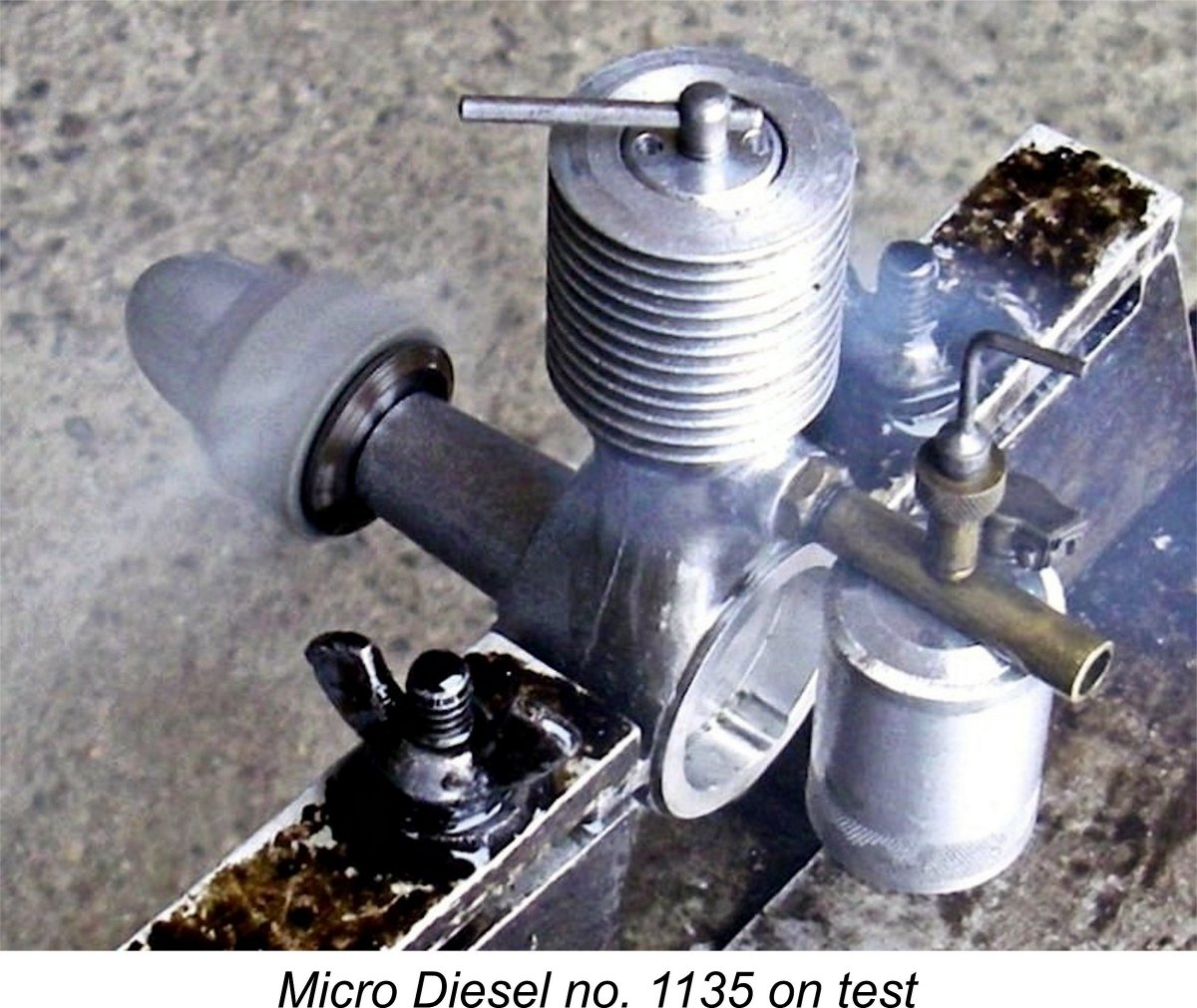
As can be seen, the refurbished CS replica delivered a good average performance for a 2 cc sideport diesel of its design era (late 1947), developing some 0.079 BHP @ 6,900 RPM. While this is well below the 0.122 BHP @ 8,600 RPM which I have measured for a standard E.D. Comp Special, it’s very comparable to the Then it was the turn of Derek Butler’s original Micro-Diesel no. 1135. The first issue that I encountered with this unit was the fact that the prop mounting thread was too short to allow for the mounting of the 11x6 prop. I had to skip that one and begin with the 10½x6, which has a somewhat thinner hub. This issue really should have received some attention from the manufacturer. The test of this engine was pretty much a carbon copy of that for the CS replica – the original engine’s handling and running qualities were identical, hence not needing to be repeated here. The big difference was in the speeds achieved with the various props, which were significantly higher with the original engine using the same props and fuel on the same day. The following figures were recorded:
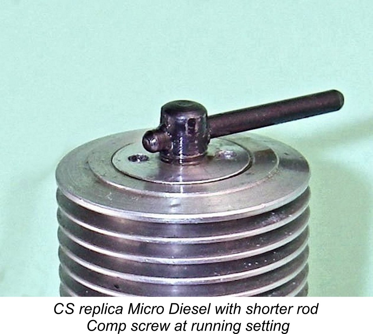
The above data confirm that the original engine delivered a very sprightly performance indeed, peaking at around 0.099 BHP @ 6,700 RPM. Virtually the same peaking speed as the CS replica, but considerably more torque. Coupled with the engine’s fine handling qualities and sturdy construction, this must be seen as a very commendable performance for a 2 cc diesel of its time. It’s a match for the Majesco and is starting to push the E.D. Comp Special fairly hard. Despite the positive results of the above testing, it has to be said that there’s no evidence here to suggest that the Micro-Diesel’s unique port timing arrangements resulted in any kind of a performance breakthrough. Indeed, as discussed earlier it seems to be more likely than not that they resulted from an uncorrected manufacturing error. The best that can be said in all honesty is that these tests confirm that the engine’s performance didn’t suffer greatly as a result of its idiosyncratic (and quite possibly erroneous) structural configuration. That said, it does seem likely that the adoption of more conventional timing figures could have resulted in significantly higher levels of performance than those measured during these tests. Finally, I’m very happy to report that both engines survived their test running with no problems at all apart from the prop driver issue encountered with the CS replica. Both units appear to be well able to give very long and useful service to their owners. A Re-Test using a Shorter Rod Seeking even more fun, I subsequently decided to test the effect of installing a conrod of more appropriate length in the CS replica. I don't like disturbing a well run-in engine, but felt that the search for knowledge required me to do so in this case. Measurements taken from the engine implied that a rod having a working length that was shorter by 2.5 mm would resolve most of the previously-noted timing issues. Moreover, the piston skirt length appeared to be short enough to accommodate such a change without contacting the crankweb at bottom dead centre. Tearing the engine down, I found that the rod as supplied had a working length between bearing centres of 36.5 mm. I therefore made and fitted a new rod having a working length of 34 mm. This change completely eliminated the former sub-piston induction, just as I'd planned. The exhaust period was now extended to 130 degrees, with the transfer following close behind at around 115 degrees. Both figures represent significant improvements over the asphyxiating numbers noted earlier. The induction period is still pretty massive at some 110 degrees, but this nonetheless represents a considerable improvement over the former 140 degree figure, especially when unaccompanied by any sub-piston induction. The use of the new shorter rod did have two undesirable consequences. First, the previously well Secondly, the fact that the piston crown was now 2.5 mm lower in the bore at Top Dead Centre meant that the contra piston had to be set lower in the bore by that amount to restore the required operating compression ratio. As the attached image shows, there was barely enough thread on the comp screw shaft to accommodate this - in fact, I ended up adding two extra turns of thread to ensure full operational flexibility. Any more, and I'd have had to use a spacer on top of the contra piston. However, neither of these issues stood in the way of a re-test! Trying the engine with its shorter rod, it was immediately obvious that a big improvement had resulted from this change. Speed on the 10x4 APC had jumped from 6,500 RPM to 7,100 RPM (0.101 BHP), while the APC 9x6 improved to 7,500 RPM (0.102 BHP) from its former 6,900 RPM. It appeared that the engine's peak had been passed on the latter prop, since the APC 9x5 now spun at 7,700 RPM (0.094 BHP), still well up from its previous 7,200 RPM. These figures imply a peak output of around 0.105 BHP @ 7,300 rpm, well above the figures of 0.079 BHP @ 6,900 rpm measured for the same engine in standard configuration. The modified CS replica now tops the original example tested earlier. I think this pretty much nails the question of the rod length in the original engine – it was an uncorrected production error. With the corrected rod length, the timing geometry makes complete sense. Moreover, performance is significantly enhanced, to the point that the engine is on par with the Comp Special and other similar contemporary models. I'm now pretty well certain that this was the intended design configuration. If I had a new and un-run example of the CS Micro-Diesel replica which I was planning to use in Vintage or Old Timer competition, I'd fit a 34 mm rod before running the engine at all. Conclusion Based upon the test results summarized above as well as the foregoing technical description of the Micro-Diesel, it’s had to see this engine as anything other than a technological success on the part of its unknown American designers and manufacturers. Indeed, in my personal opinion it must rank as one of the finest diesels to emerge from the early post-WW2 American model engine manufacturing industry, The tragedy of the Micro Diesel is that it was launched onto the American model engine market at the exact moment when Ray Arden’s introduction of the commercial miniature glow-plug triggered a general stampede among American modellers towards the universal adoption of the new form of ignition. Had that event not taken place when it did, there seems to me to be little doubt that on merit alone the Micro-Diesel would have achieved a respected place in American modelling circles. If arrangements could have been made to market the engine in Europe, there’s no doubt at all that it would have been very well received. Moreover, any additional engines which might have been manufactured under these circumstances would almost certainly have had the issue of the conrod length resolved, since there would then have been both an opportunity and a financial incentive to do so. The above evidence suggests that engines produced with this seeming error corrected would doubtless have performed even better than the original batch. The final word must surely be reserved for CS. Once again we are reminded of what the classic modelling world lost when CS decided (or were forced) to end all model engine production in late 2015. The CS replica of the Micro-Diesel is a very effective substitute for the real thing if one wishes to experience the rather unique handling characteristics of this very original design. If you have the equipment and ability, it can even be turned into a fairly close visual representation of the original with an excellent performance to boot. So once again, hats off to CS – I for one miss you guys! ________________________ Article © Adrian C. Duncan, Coquitlam, BC, Canada First published August 2017 Revised September 2017 Second revision May 2018
|
||
 In this article, we’ll take a close look at an extremely elusive American diesel from the latter part of the 1940’s. This is the .13 cuin. (2.13 cc) Micro-Diesel, which was manufactured in relatively small numbers in Detroit, Michigan and marketed between late 1947 and late 1948.
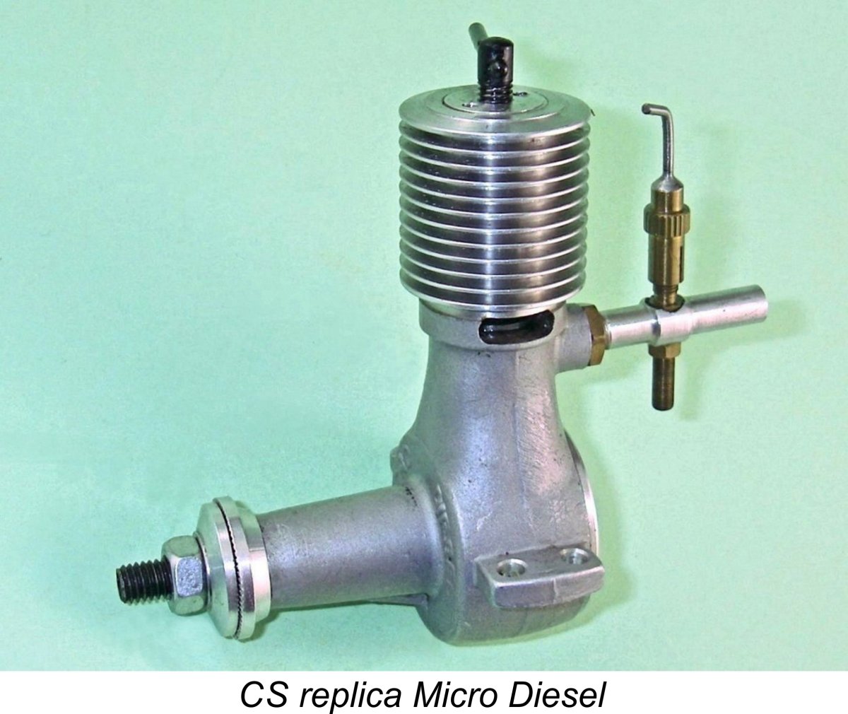
 In many ways this must be seen in hindsight as a great pity. American mass production techniques were virtually unsurpassed at that time. Moreover, American model engine designers and manufacturers possessed a great deal of practical know-how gained over a decade or more of high-volume manufacturing experience.
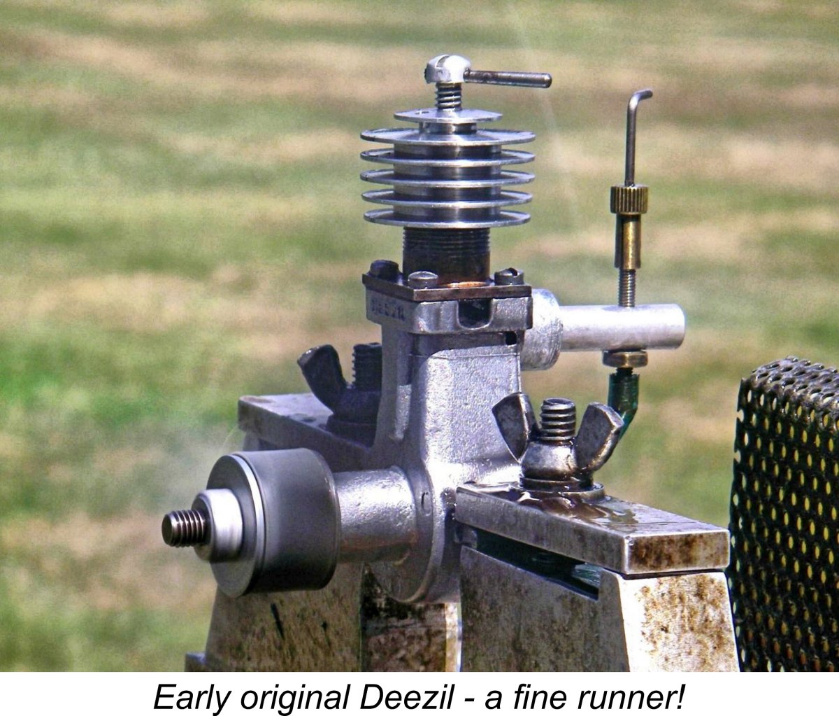
 The first actual media reference to the engine of which I’m currently aware came in the form of a
  seems that Ingram’s article may have been a compilation of descriptive paragraphs written independently over an extended period of time during 1948 and that the Micro-Diesel was one of the first engines for which a paragraph was drafted relatively early in that year. I can think of no other explanation.
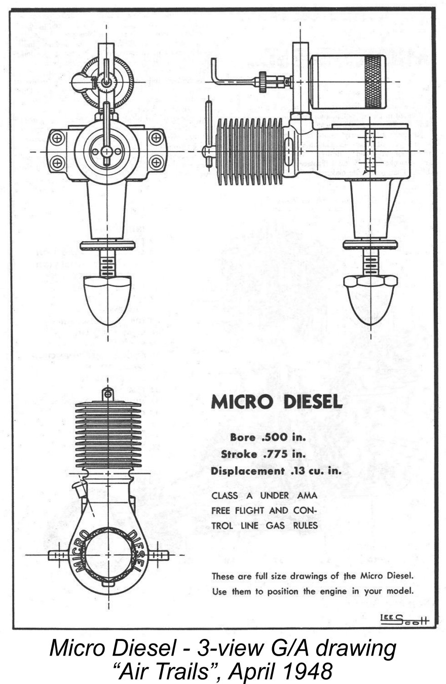 When setting out to describe this engine, we immediately run into a significant anomaly which urgently requires resolution. The engine’s nominal bore and stroke were given by the writer of the “Air Trails” test as 0.500 in. (12.70 mm) and 0.775 in. (19.68 mm) respectively, as seen on the attached 3-view General Arrangement (G/A) drawing extracted from that test report. However, both the writer of the test report and the manufacturer's advertising cited the engine’s displacement as 0.13 cuin. (2.13 cc).
 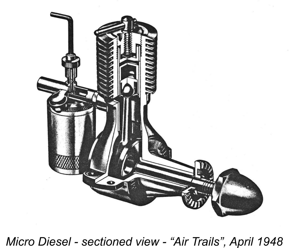 Apart from some noteworthy anomalies in its port timing which will be discussed in detail in the following section of this article, the Micro-Diesel initially presents itself as a fairly conventional sideport diesel of its era. It is constructed around a main gravity die-casting which incorporates the crankcase, the main bearing housing, the exhaust apertures, the rear induction boss and the upper cylinder jacket in a single unit. The cooling fins are turned directly onto this casting, having a tapered lateral section for improved heat dissipation.
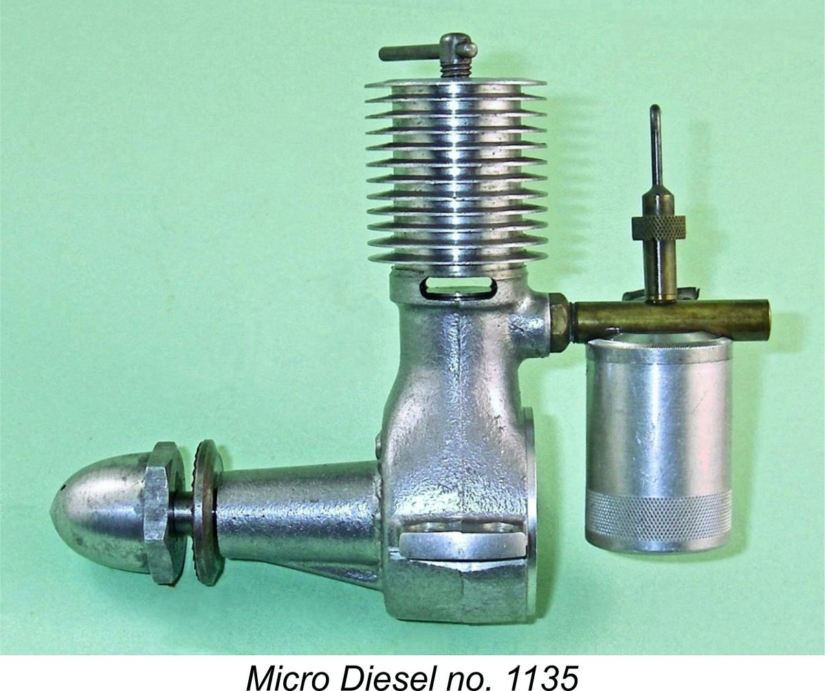 Both the contra piston and the piston itself are of steel. The contra piston is activated by a single-arm compression screw of conventional form. Some commentators (including Arne Hende) have claimed that the Micro-Diesel was the first American diesel to use a system of variable compression involving a contra piston. This is untrue – the earlier
 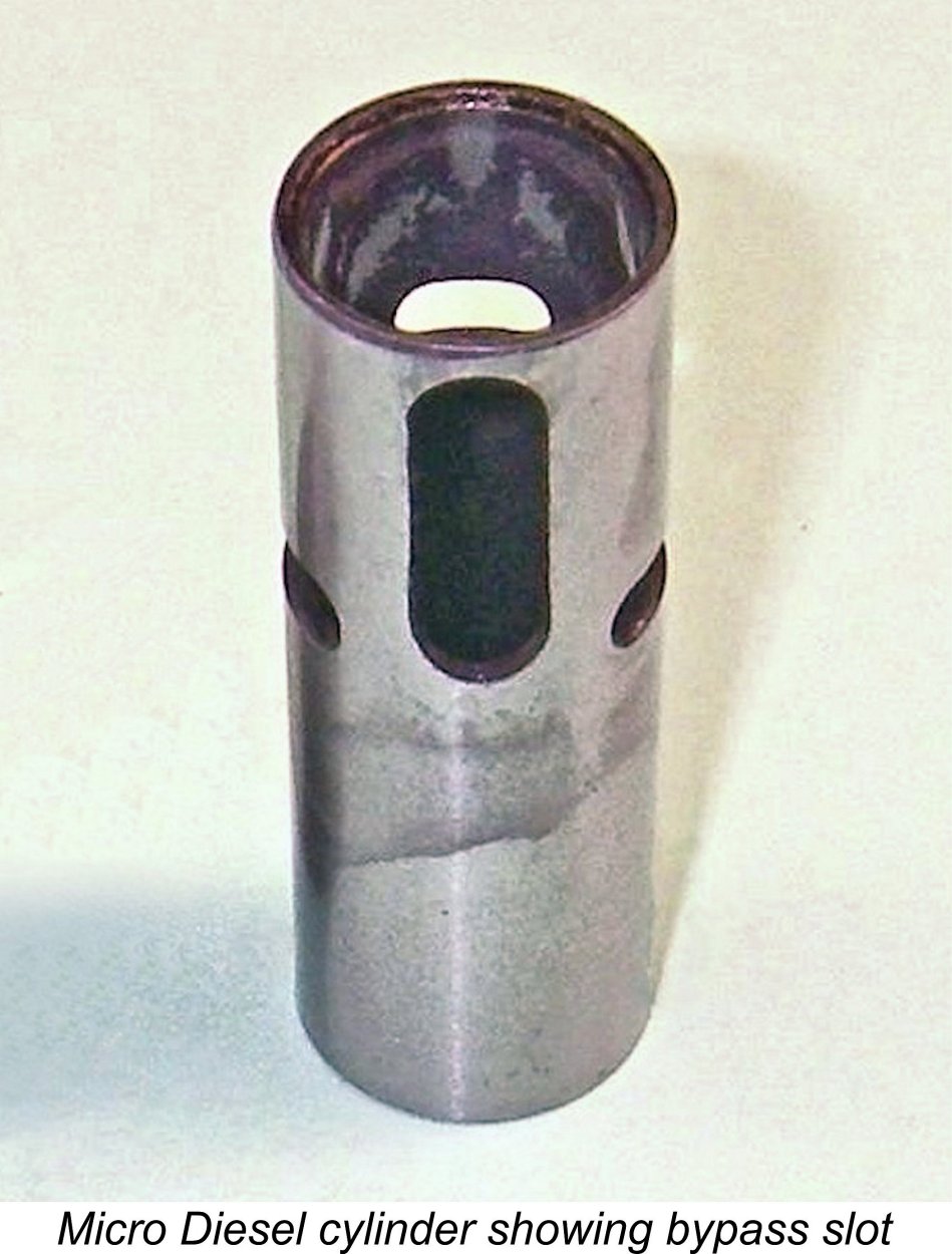 The cylinder is provided with the usual ports for a sideport diesel – a single induction port at the rear, a single transfer port at the front and a pair of exhaust apertures, one on each side. The most interesting feature is the design of the bypass. This is created by milling a long vertical slot in the front of the lower cylinder wall. The top of this slot projects above the piston crown at bottom dead centre (BDC) to serve as the transfer port, while the bypass consists of the space created by the vertical slot between the piston wall and the inner face of the main casting.
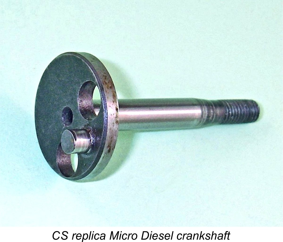 Moving on downwards, the steel crankshaft is a composite component consisting of the main journal and crankweb in one piece, with a separate pressed-in crankpin. Two fairly large holes are drilled in the crankweb on either side of the crankpin to provide some counterbalance. The main journal runs in a closely-fitted bronze bushing. A steel prop driver is used along with a nicely-finished spinner nut of light alloy.
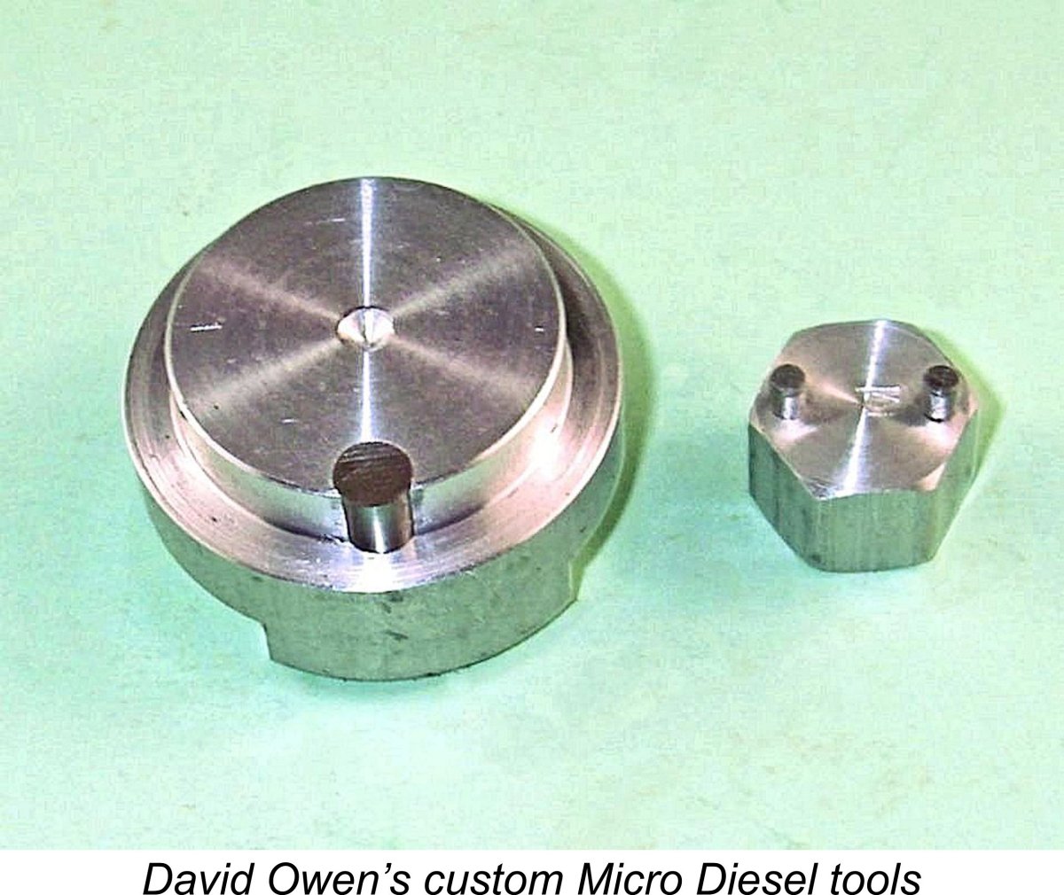 This highlights a point which is well worthy of comment. The designers appear to have gone out of their way to make tampering with this engine more challenging than usual – a very wise move! Both the two-hole purchase provided for the cylinder head and the keying arrangement for the backplate require the use of tools to which the average owner would not have access. The attached illustration shows the tools made for Derek Butler by the late David Owen. Owners of these engines are respectfully asked to please refrain from disturbing their examples using anything other than the correct tools – conservation is important!
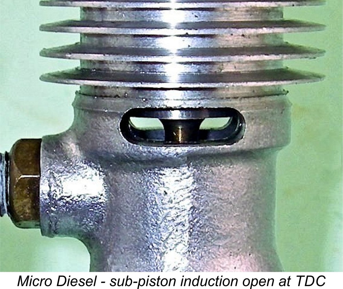 In the previous section of this article, we finally put one anomaly to bed – we now know the Micro-Diesel’s true displacement. However, when we come to consider the engine's port timing figures, we run head-on into another anomaly! One’s awareness that this engine is different begins when one notices its truly massive sub-piston induction. At Top Dead Centre (TDC), the two quite large exhaust ports are both almost fully open, giving a sub-piston induction period of no less than 80 degrees (40 degrees each side of TDC) along with a massive port area.
 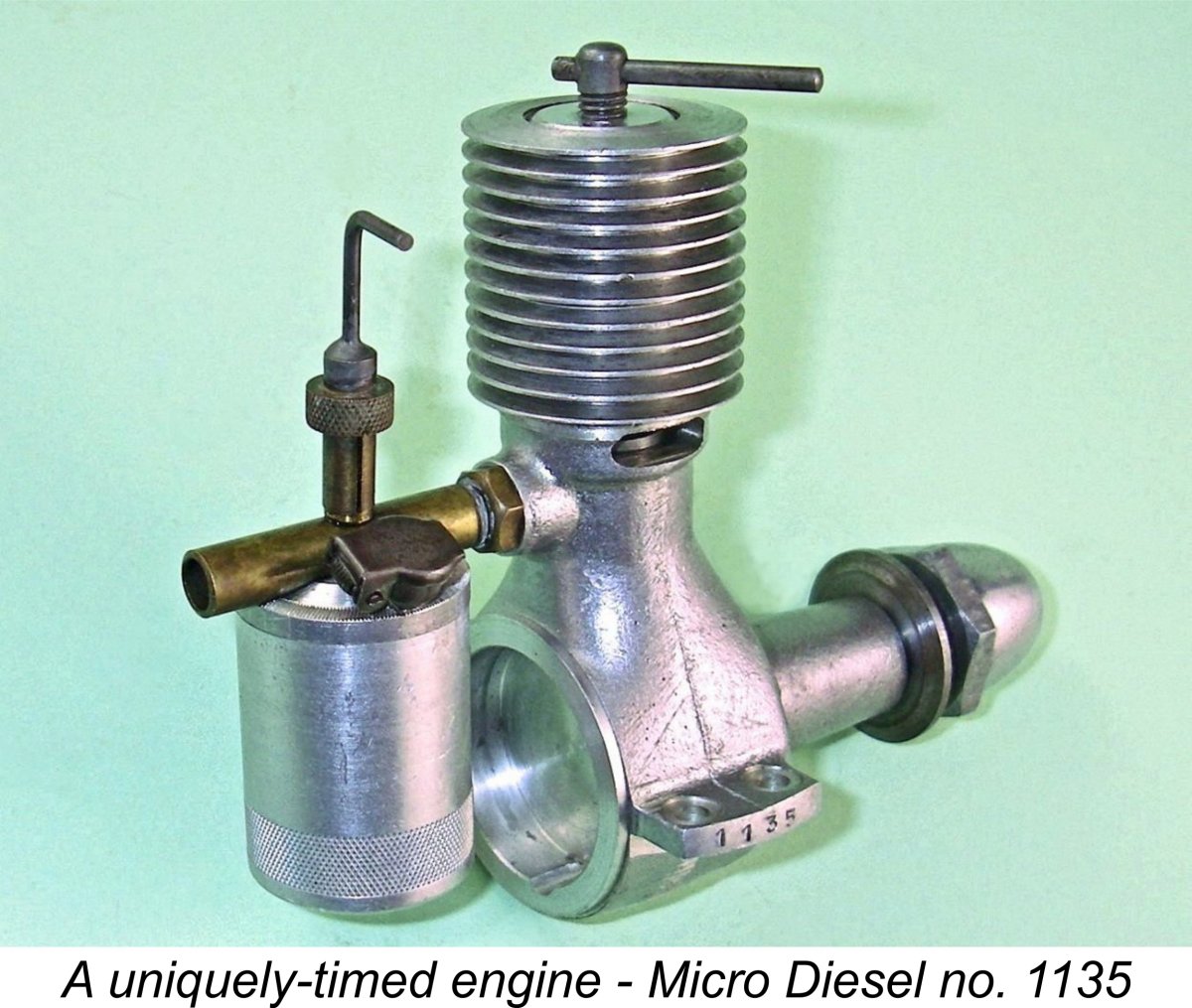 The timing of the engine's exhaust port opening also differs considerably from that of other similar engines. The exhausts open unusually late at 132 degrees ATDC for a total exhaust period of only 96 degrees - considerably shorter than usual, even for a low-revving sideport diesel like this one. The opening of the transfer port at 140 degrees ATDC provides a blow-down period of only some 8 degrees - a not unreasonable figure. However, it must be said that overall these are very unusual figures, even for a relatively low-speed sideport diesel.
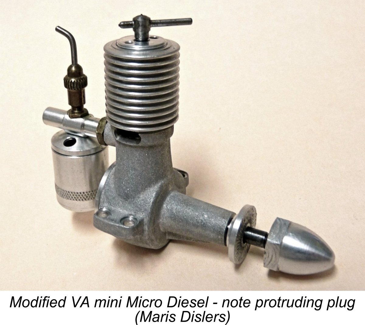 This of course raises the ultimate question - once the error became apparent (as it surely would upon close examination of the assembled engines in that first batch), why didn't the manufacturer take action to correct the situation? The simplest solution would have been to raise the cylinder through the use of a spacer at the base. Maris Dislers has tried this approach with his example of the VA/Dave Banks mini Micro-Diesel (see below), which replicated the oddball timing of the original. His
 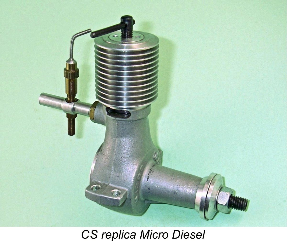 The CS replica Micro-Diesels were made in Shanghai, China during the period 2004 - 2008. As mentioned at the outset, the CS Micro Diesel is a fairly close copy of the basic original engine, also generally being very well made. Perhaps unfortunately, it replicates what may well be the erroneous timing of the originals. However, it does embody a number of obvious departures from the design of the original. The main differences are as follows:
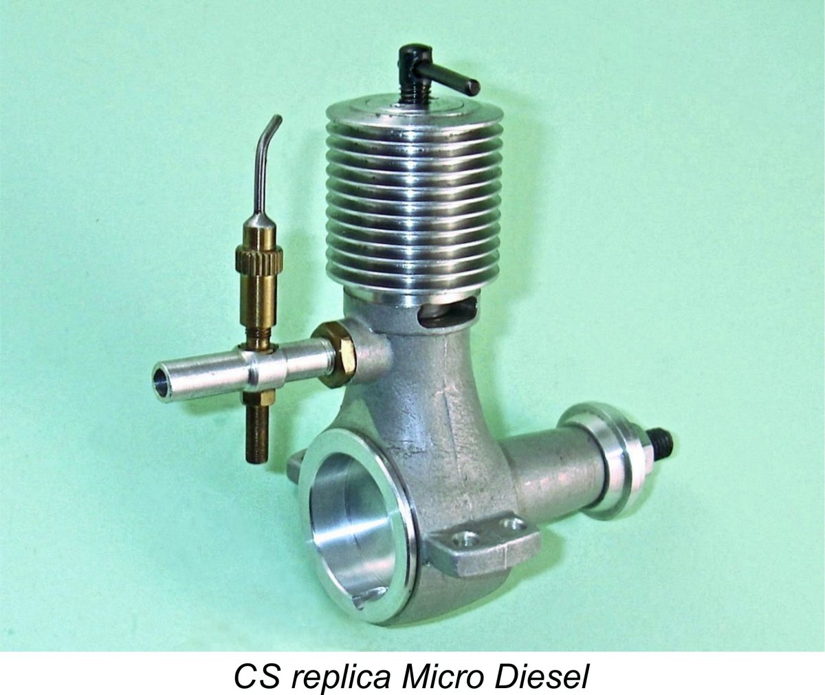 The visible differences noted above are more than sufficient to allow one to immediately differentiate between the original Micro-Diesel and the CS replica. However, these differences do not greatly alter the fact that the CS replica is a perfectly acceptable stand-in for the real thing, sharing the same porting arrangements and highly individualistic timing. The quality of manufacture of my illustrated example is very good, the one exception being a slightly uneven finish in the con-rod big end bearing which doesn't appear to affect the engine in any way.
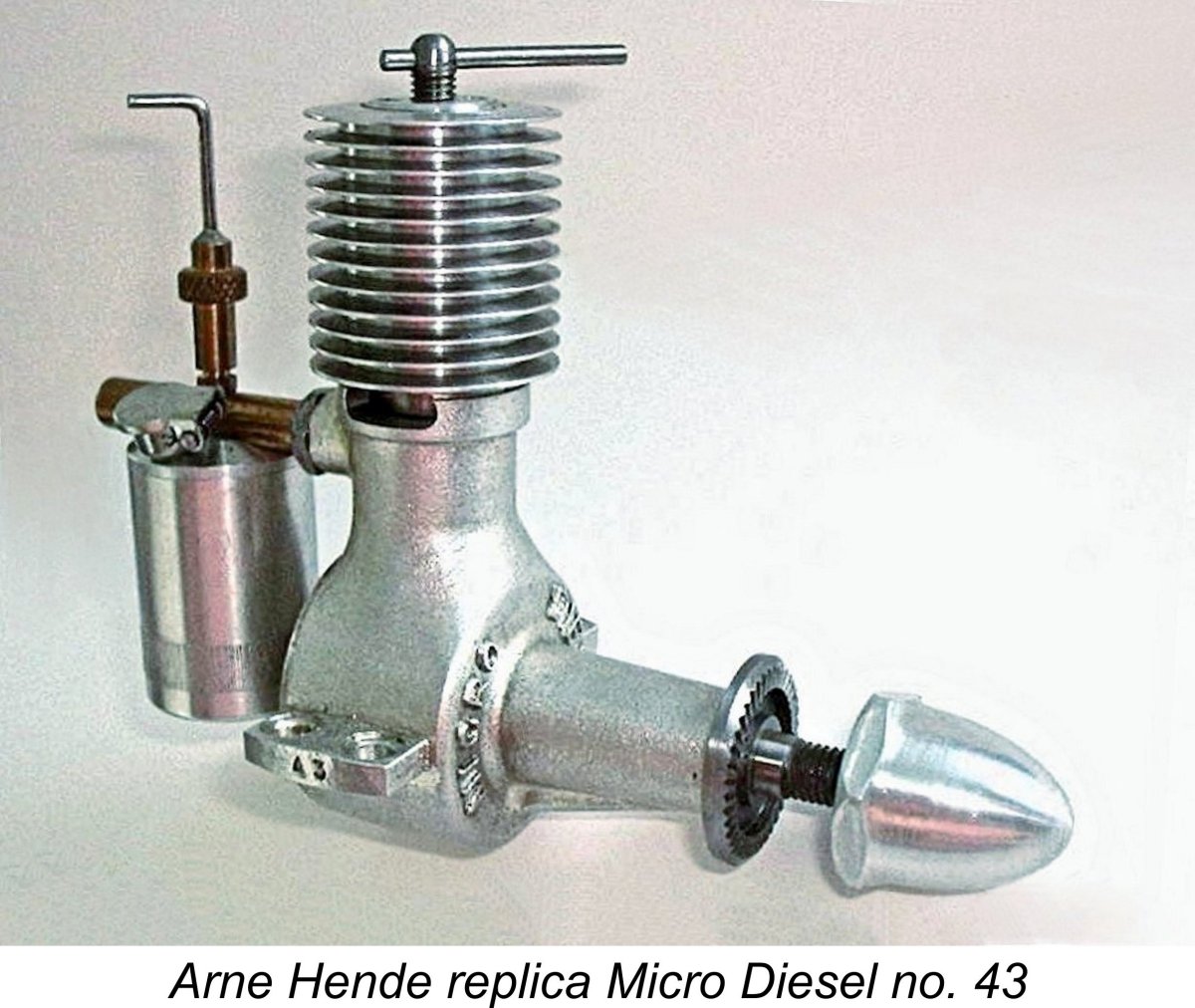 The famous Swedish model engine replicator Arne Hende (1933 - 2007) arranged for the production of a relatively short series of extremely faithful reproductions of the original Micro-Diesel. Arne typically had his replicas made in batches of 100 units, and that's probably how many of these engines were manufactured. I've never encountered a three-digit serial number.
 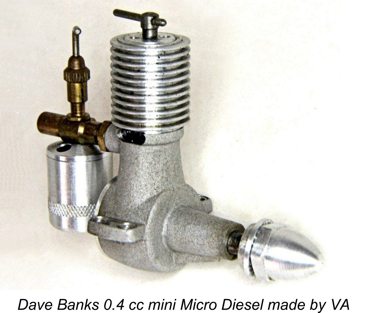 During the mid to late 1990’s, Dave Banks of England arranged with the Russian VA company (Valentin Aljoshin) of St. Petersburg for the production of a series of mini-replicas of a number of classic model diesel engines. These included the E.D. Bee, the Mills .75, the Elfin 1.8, the Elfin 50, the E.D. Baby, the Kalper .32 and our main subject, the Micro Diesel. All were very well made and performed at most acceptable levels for their size. They really started the trend towards small diesel-powered F/F and R/C models.
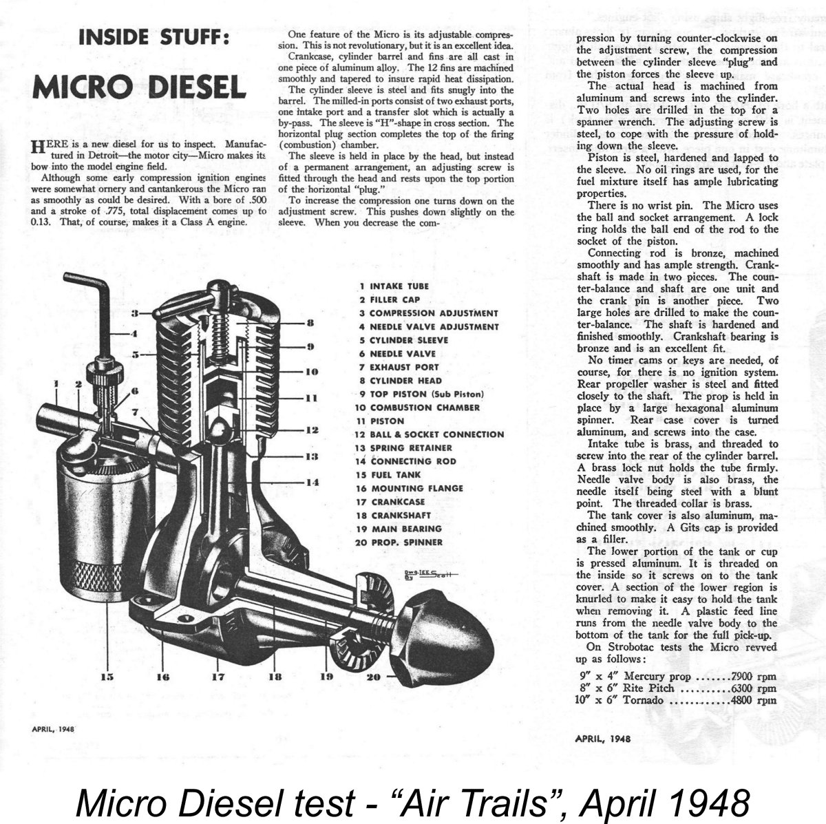 As mentioned earlier, the original Micro-Diesel was the subject of a test report which appeared in the April 1948 issue of “Air Trails” magazine. This is the article which quoted the incorrect bore and stroke dimensions noted earlier. Apart from that, it provided a reasonably comprehensive and accurate description of the engine.
 The original example of the Micro-Diesel used in this test (engine number 1135) was obtained by present owner Derek Butler from Jim Gerrard, the former MOKI dealer for the USA. It was supplied in as-new condition, but was torn down and fettled by the late David Owen, who relieved a slightly tight main bearing fit. David also made the previously-illustrated special tools for dismantling and re-assembling the engine.
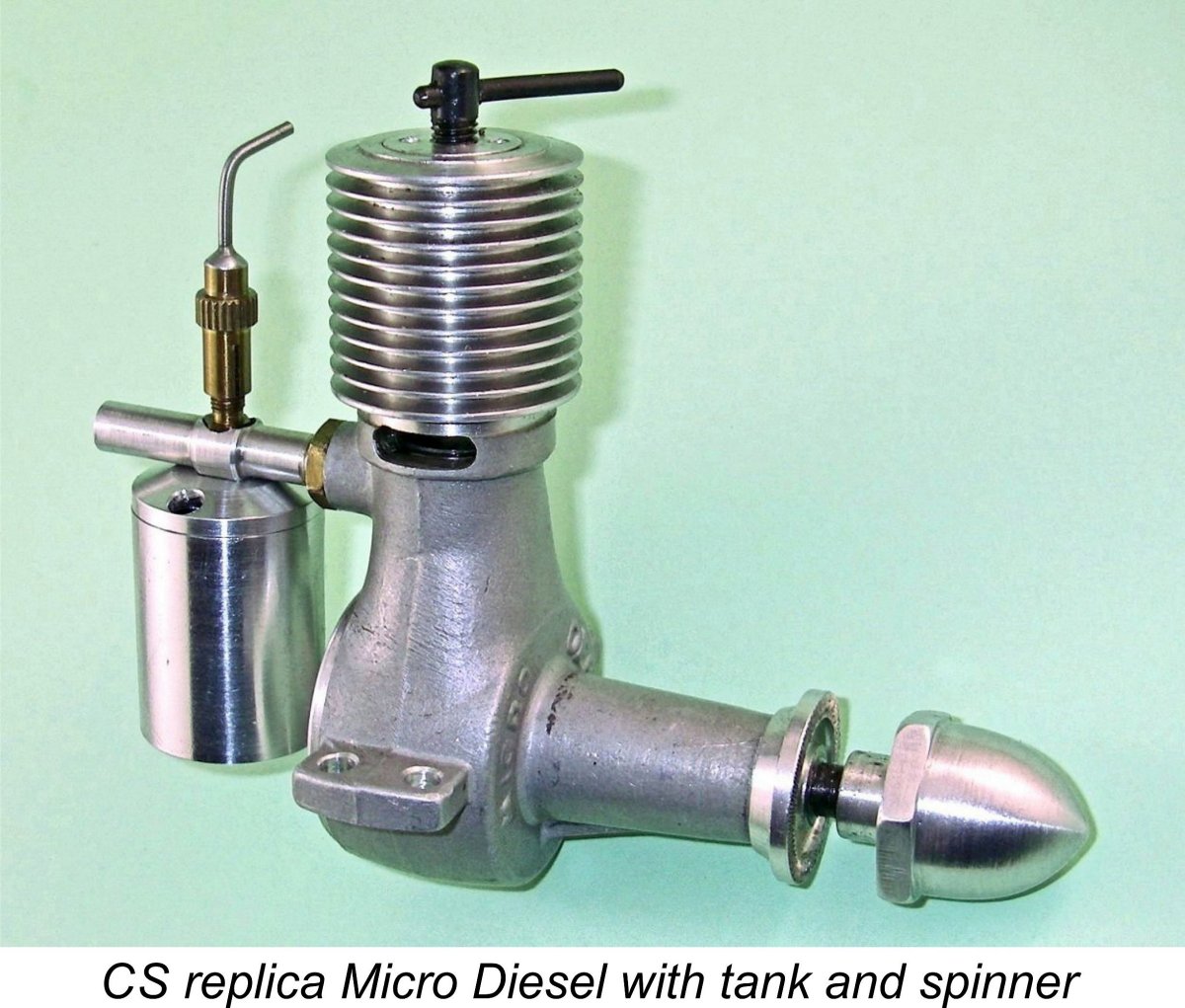 I had acquired my own CS replica on eBay some years ago but had not previously found an excuse to get to grips with it. The engine had clearly done some running, although it didn’t appear to have been mounted in a model. With its cast iron piston having been run in to a perfect fit, it felt really good and was undoubtedly all ready for some serious test running.
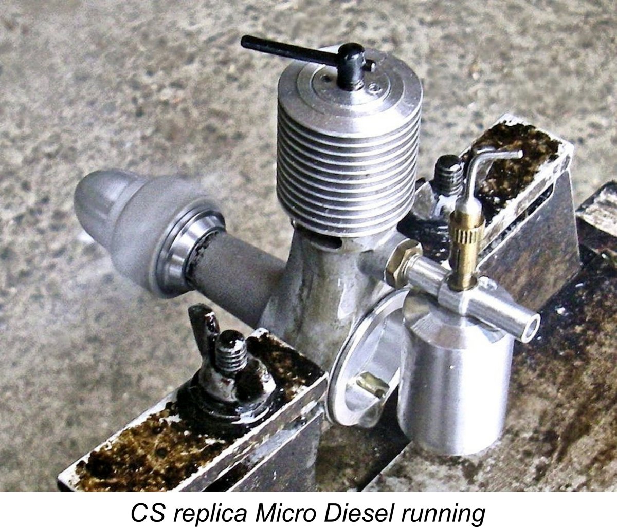 I picked a day when the snow was falling and all the neighbours were either at work or indoors, so that I felt comfortable testing the engines at home. First into the test stand was the CS replica. Thanks to the extended hub on the spinner nut, I had no trouble fitting the 11x6 prop with which I started out. I used an oily fuel containing 30% castor oil plus a modest 1½% dose of ignition improver. With the tank filled with this fuel, I set the needle at 2 turns open, administered a small prime and got stuck in.
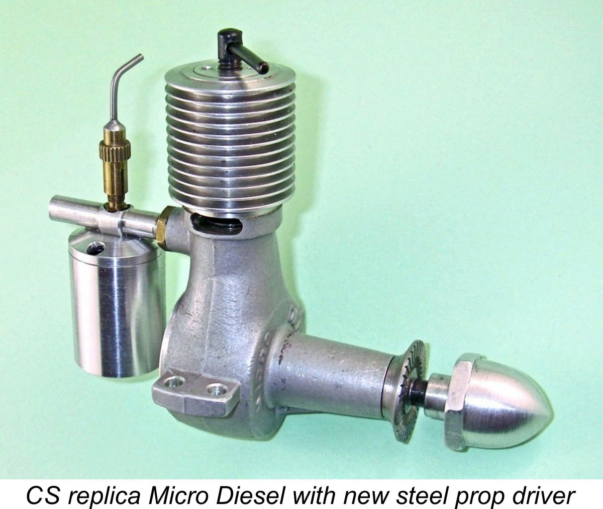 The relatively short standard light alloy prop driver clearly proved unequal to the stresses imposed. I’m unable to say whether this is a chronic design fault or was due to a flaw in the material of this particular prop driver. All I can say is that I wasn’t using undue force when tightening the various props in place.
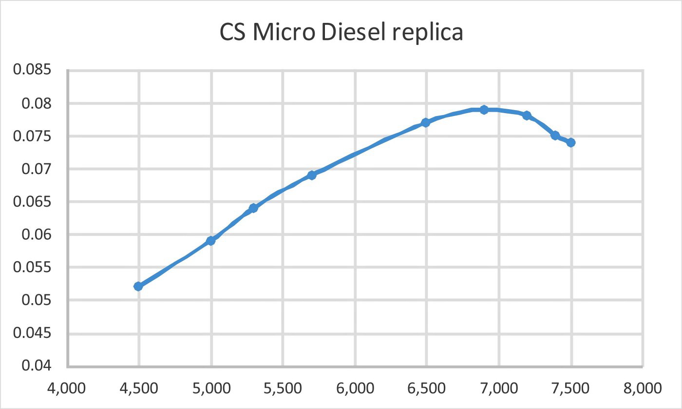
| |