
|
|
Dennis Allen’s Final Fling - the AE Engines by Allen Engineering
In 1961 D. J. Allen Engineering took over the manufacture of the MERCO glow-plug motors from the Model Engine Research Co. Ltd. owned by Bill Morley and Ron Checksfield. The wisdom of With the MERCO engines selling as fast as they could be manufactured and the A-M diesel range still in production, the company was now working at full stretch. It has been reported that at its peak, D. J. Allen Engineering employed as many as 30 people in making the engines. At some point during 1963, Dennis Allen sold his interest in the company to others, quite possibly to his partner Les Parker. Allen’s departure may have been prompted by the firm’s increasing market-driven focus on glow-plug engines – although he was very much involved with glow-plug technology, he remained a staunch diesel man at heart, as his later activities were to demonstrate quite convincingly.
Two years were spent developing these highly innovative designs, with production commencing in 1983. Unfortunately, the very high manufacturing costs involved made the project uneconomic, resulting in the cessation of production after only some 500 units had been completed. The Condor engines are highly desirable collectors’ items today. Dennis’s next venture is the one which concerns us here. This was his Allen Engineering (AE) range of diesels which were manufactured from the latter half of the 1980’s to the mid-1990’s. The balance of this article will focus strictly upon those models. An earlier article by the late Ron Chernich on the AE engines appeared on Ron’s wonderful “Model Engine News” (MEN) website in February 2004. However, the heavily-encrypted MEN site is slowly deteriorating due to the sad fact that Ron left us without passing on the access codes so that it could be maintained. Accordingly, I’ve elected to develop my own article on the AE range for publication on this website, incorporating all of Ron’s observations along with my own comments to guard against the potential loss of Ron’s information. In particular, I’ve drawn heavily upon Ron’s descriptive material while correcting a few errors and adding a number of my own insights. ‘Nuff said - let’s get right to it! The AE Range – Production History
Apart from the tiny radially-mounted 0.1 cc unit, all models were beam mounted. Although no record-breakers, they were useful sports diesels which ran well, albeit at relatively modest levels of performance. The little 0.1 cc model was somewhat finicky, although a good example ran fine once the owner got to grips with it. That said, quality of that model was reportedly somewhat variable - the extremely high level of precision required at such a small displacement seems to have stretched the production capabilities of the manufacturer. Engines of this tiny size tend to be best made individually rather than being produced in series in larger quantities.
The various models were evidently introduced sequentially in the order in which their designs and tooling were completed. My good friend and valued colleague Gordon Beeby of Australia assisted me immeasurably in connection with this issue, tracking down a number of media references and advertisements which appear to provide very solid evidence for the dates applicable to these engines. The most informative series of advertisements were those placed in “Aeromodeller” by Michael’s Models of Finchley, who became Engines Unlimited in early 1995.
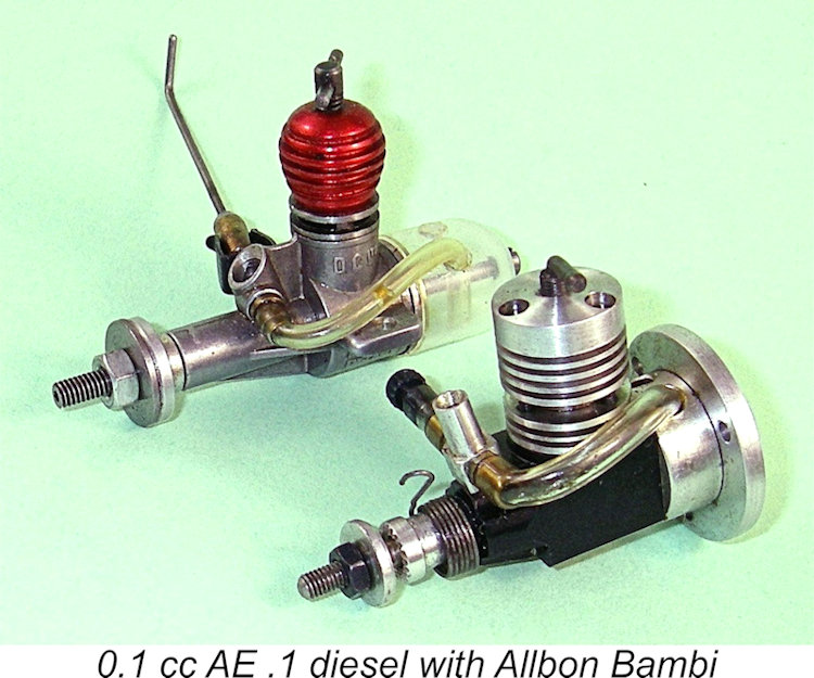
The advertising debut of the remarkable little 0.1 cc AE .1 in December 1991 triggered a surge of interest in Dennis Allen and the engines that he was producing. It’s hard to escape the suspicion that the development of this tiny diesel was triggered as much as anything by Dennis This remarkable little unit was the smallest-displacement engine ever to achieve series production in Britain, supplanting the Allbon Bambi in that role – indeed, it was probably the smallest-displacement series production unit ever to appear anywhere, although it was actually physically a little larger than the Bambi owing to the barstock construction.
The January 1992 issue of “Aeromodeller” featured an article entitled “Dennis Allen – Motor Maestro” by Ron Prentice, in which the AE engines were mentioned and a visit to the factory was described. The 0.1 cc AE.1 was said to be just reaching the market at Ron’s time of writing, a statement which is consistent with other evidence. Maintaining the momentum, the “Engines Old and New” feature in the March 1992 issue of the magazine covered Having brought all of the AE engines having displacements of 1.5 cc or less into production, Dennis returned to the development of the larger prototypes which had first appeared in May 1989. A new 2.5 cc twin ball-race model, the AE 2.5 BB, was tested in the “Engines Old and New” feature in the August 1993 issue of “Aeromodeller”, although the first dealer advertisements for this model didn’t appear until November 1993. When they did so, they offered both standard and R/C versions of the engine. The January 1994 issue of “Aeromodeller” included another edition of the “Engines Old and New” feature, this time written by my friend Jim Woodside, on the subject of the 0.1 cc AE.1 and 0.2 cc AE.2 units. Jim had amassed a considerable amount of operation experience with both of these units, having built a series of models expressly for them. In his article, he summarized his generally positive experiences, passing along a number of invaluable operating tips. Required reading for anyone planning to try running one of these little gems!
The Engines Unlimited advertisement of March 1995 no longer featured the 0.5 cc AE .5 model, which seems to have disappeared from the range by this point. This may have been a reaction to the introduction of the far more powerful P.A.W. 55 at around that time. However, sales of the AE engines in general were now evidently slowing down considerably. Production of the AE engines appears to have ceased in early 1996, although the range continued to be listed in dealer advertisements for some time thereafter, presumably on the basis of existing New Old Stock. This could explain the otherwise inexplicable omission of the AE range from Jim Woodside's article entitled “Small Diesels – the Best of Times” which dealt with then currently-available small diesels, forming part of the April 1996 issue of “Aeromodeller”. The AE miniatures were omitted despite the fact that the full range other than the 0.5 cc model continued to appear in the Engines Unlimited advertisement in that issue. As a user of these engines, Jim presumably knew that production of the range had been terminated when he submitted his article. By August 1996 the Engines Unlimited advertisement stated unequivocally that production of the AE range had ceased, with only a few units still being available from stock. Even then, those last examples seem to have been slow to sell, because the January 1997 advertisement offered the remaining engines at a discount, stating that “only the last few” were left. The production life of the AE engines and the relevant dates thus appear to be very well documented. Production of the range appears to have been confined to the period between mid-1987 and early 1996. The engines were introduced progressively, starting with the 1.5 cc model and finishing with the 2.5 cc variant. They were presumably made in batches as dictated by the order book. Since they didn’t carry serial numbers, it’s impossible to say with any certainty how many examples of each model were produced. However, the era of the sports diesel was coming to an end at the time, making it seem unlikely that they were manufactured in really large numbers. They seem to be encountered relatively rarely today. The AE engines proved to be Dennis Allen’s final venture into the world of model engine manufacture. After ending production of that series, he went into semi-retirement, ending a 46-year continuous involvement with model engine design and manufacture. Of course, he couldn't abandon the field completely - he continued to make glow-plugs on a part-time basis in a small workshop which he established at his home. He also continued his life-long involvement with aeromodelling, focusing on stunt R/C gliders, power-assisted gliders and whatever else he fancied! Somewhat strangely (to me at least), he never became involved with the vintage movement, feeling that to do so would represent a step backwards because he had already “done that”. Dennis was clearly not given to attacks of nostalgia! Too bad - he would have been welcomed very warmly! Time now to take a closer look at the engines themselves. And who better to guide us through this process than my late and much-missed mate Ron Chernich? The AE Engines – General description The bulk of the following comments were extracted from Ron Chernich’s previously-mentioned article about the AE range which appeared on Ron’s MEN website in February 2004. I’ve made a few editorial changes and inserted a few insights of my own, but otherwise I’ve preserved Ron’s comments much as he wrote them.
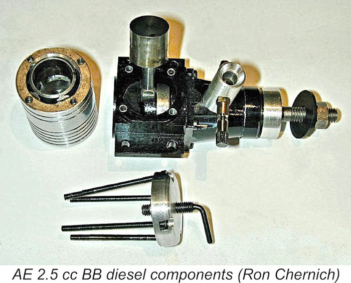
The subject of the partially-dismantled shots here is the 0.5 cc model from Ron’s collection as it stood in 2004. The main crankcase has a simple cruciform section produced by a shaper, being bored to accept the front journal housing and cylinder liner. There is no "backplate" as such; it is integral with the case. Looking at the rear views of the various models in the previously-attached group shot, what appears to be a backplate is simply a counter-bore to remove some excess material from the case, plus an artsy turning on the end to clean it up and give the illusion of a traditional screwed-in backplate. Next, check out the massive crankweb. The reason for the thickness of this component is to provide support for the crank-pin, which is pressed in. No attempt has been made on any engine in the range to counter-balance the crankweb. Fair play to Dennis Allen - experience suggests this to be a waste of time in sports engines of these displacements, a fact which he clearly recognized. The front housing is turned to a conical form and counter-bored to provide seats for the four 8BA mounting screws, resulting in an appearance suggestive of "strengthening webs". The venturi fits into a hole bored into the cone, very much like David Owen's Mate design, although on the AE engines it is secured with one or two small set-screws, allowing it to be angled as desired or replaced by an R/C carburetor. The needle and The piston is turned from steel rather than the more usual cast iron. This results in a steel-in-steel piston/cylinder combination, which can be problematic in service unless the initial fit is pretty much perfect, as makers such as J. E. Ballard & Co. discovered to their cost. However, the advantage is that the wear rate will be minimal, which is a real plus for very small engines like the AE .1 and AE .2 models given the extreme sensitivity of such small engines to any trace of piston leak-down. The materials appear to have been chosen with a view towards extending the working lives of these tiny powerplants. The piston crown is a truncated cone, presumably to assist scavenging without the need to produce a concave cone in the contra-piston. It is fitted with a pressed-in gudgeon (wrist) pin and a turned aluminium conrod. Notice how the milling of the big end of the rod shown here has been carried just a bit too far and has nibbled away on the rod shank. Not that Ron would presume to criticize the work of anyone as experienced as Dennis Allen, but for another approach, see the method which Ron deduced from Gordon Burford's Taipan series.
As seen here, the bypass passages are formed by shallow milling inside the lower aluminum finned section that sits clamped on two thin brown paper gaskets between crankcase and cylinder flange. This arrangement requires that everything be assembled in the correct radial alignment so that the bypass passages correspond with the transfer ports. The location of the cylinder "posts" relative to the cylinder bolts provides sufficient visual guidance to ensure correct assembly. The engine pulled down for this investigation was a New-In-Box (NIB) example, so Ron was surprised to find the familiar black glue-like accretion of well-congealed castor oil to be much in evidence. This indicated that the engine had been factory-run. This finding earns the engine a big tick for this extra Q/A expense, although a solvent flush followed by a few drops of after-run oil would have been appreciated.
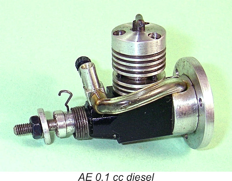
The little beauty is fitted with a spring starter, which I consider to be virtually a necessity with very small diesels (even though the 0.15 cc "Bambi" is well capable of first flick starts with the correct technique). Why do I say this? Well, very small diesels require an extremely rapid passage through the compression stroke for starting (hence the Bambi team-race "clobber"), which a spring starter is well able to deliver. But perhaps more importantly, such a starter is actually very protective of the engine. This is because any attempt to force the engine over compression when in a hydraulic lock condition or nearly so (easily done unintentionally when hand-flicking) will be fatal to the structural integrity of such a small unit.
The two-piece spray-bar comprises an internally-threaded length to hold the externally-threaded needle and a separate jet and fuel nipple, both components being screwed into the venturi from opposite sides. A short length of PVC fuel tubing serves as the friction device for the needle itself. The PVC tubing trick, more normally seen on amateur-constructed engines, is very effective at stabilizing the needle setting, although the tubing tends to harden in service, requiring periodic replacement. Jim Woodside recommended the replacement of the PVC tubing with soft rubber tubing such as black Kavan fuel tubing.
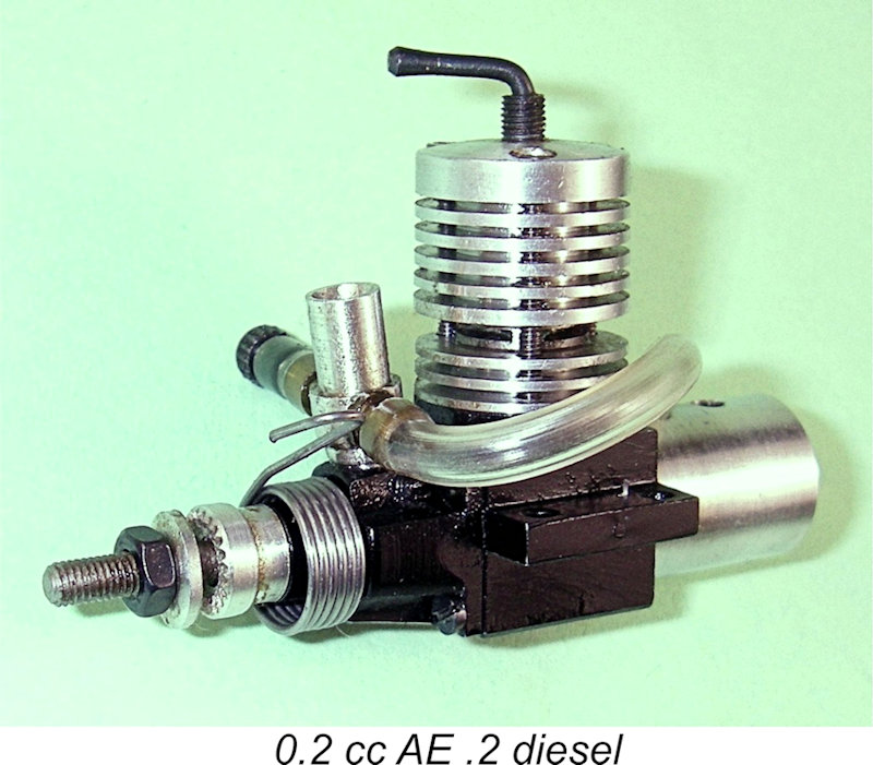
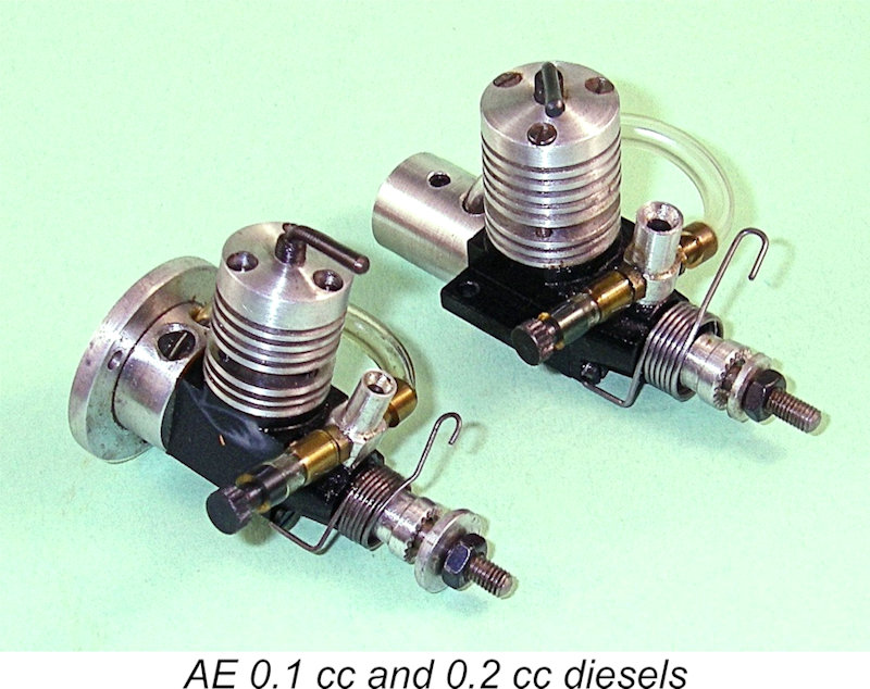
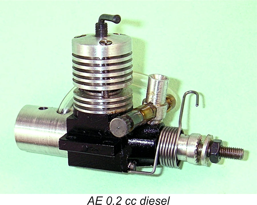
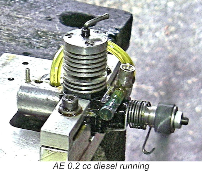
Next up is the 0.2 cc model (0.0122 cuin.). This engine differs from the 0.1 cc model in featuring beam, as opposed to radial, mounting. It also differs slightly from the 0.5 Mk. I, 1.0 and 1.5 cc versions in being fitted with a rear mounted fuel tank. Two other differences from the latter three models are apparent in the shape of the compression screw (an L rather than a T), and the needle valve, which follows the 0.1 cc pattern in using a two-piece spraybar with a short length of PVC fuel tubing serving as the friction device. This model too is fitted with a spring starter, although experience shows that it can be started easily enough by hand if both care and experience are brought to bear.
This seems to be the point at which to mention the downside of that arrangement to which reference was made earlier. The “Aeromodeller” test reported that the PVC tubing friction system resulted in a degree of spring-back after releasing the needle following an adjustment. This may sound rather inconvenient, although the tester asserted that the effect could be compensated for by turning the needle slightly past the desired setting and immediately releasing it to allow it to spring back instantly to the desired setting.
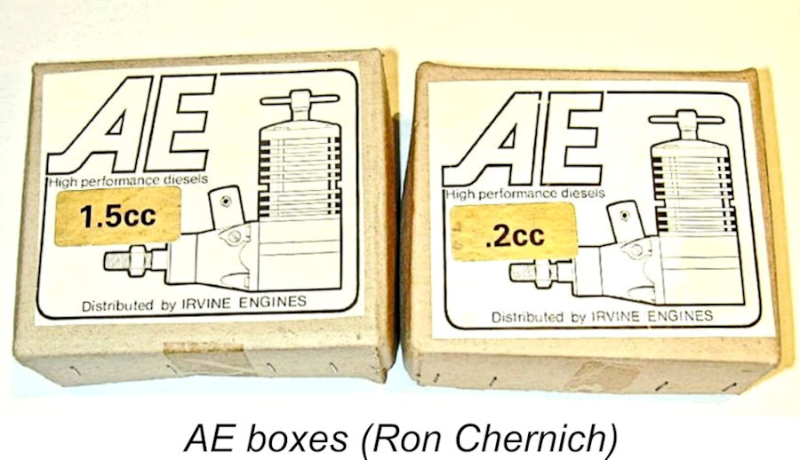
The steel liner for this engine is cylindrical with a flanged top. In the photo, the Schnuerle "boost" transfer passage is towards the camera; the exhaust is on the far side. The whole assembly is clamped tight by the plain head with a brown paper gasket sealing jacket to case. The head bolt pattern is The four smaller engines shared a common box and instruction sheet. The displacement was identified by a gold stick-on label on the front or end of the box. The AE 25 required a larger box, which was also used for the later examples of the other models, presumably to maintain commonality among the boxes. The common instruction sheet gave the recommended prop sizes for the middle three engines. A small type-written supplementary sheet provided some additional handling suggestions and recommendations for the 0.2 cc and 0.1 gnats. The AE Engines on Test Considering the extent of the AE range, which included no fewer than six models (more if you count the R/C versions) having displacements ranging from 0.1 cc up to 2.5 cc, it seems a little surprising at first glance that only one of the engines in the range was ever the subject of a published test report. The explanation for this comparative neglect is of course the previously-mentioned fact that by the 1990’s the age of the small sports diesel as a mainstream hobby item for which a viable market existed was rapidly drawing to a close. The interest of modellers in general was then focused upon larger R/C glow-plug engines. Consequently, it was those engines which drew the attention of the engine testers of the day away from the small sports diesels. Even those R/C glow units were soon to go the same way as the diesels as the soul-less electric push-button revolution gained momentum along with the bought-in-a-box ARTF’s and drones. For me and for many others, the wonderfully creative and rewarding hobby that I knew and loved for over half a century was dying. Between designing and building a model by hand from scratch and unpacking a box, there’s no comparison in terms of a sense of accomplishment. Moreover, pushing a button to start the motor can't deliver anything even remotely close to the satisfaction of achieving a start by flicking the prop and adjusting a well-sorted I/C engine for a perfect motor run ……… who’s ever going to collect electric model airplane motors?!? To be collectible, an item must have a soul! Most of today’s model fliers will never know what they’ve missed…………..aeromodelling as generally practised has become an activity rather than a hobby. I feel blessed to have experienced the hobby stage. The two “babies” of the range – the AE .1 and AE .2 models - were admittedly the subject of two reports which formed part of the previously-mentioned “Engines Old and New” series. However, neither of these references could be viewed as a true "test report" since they contained no performance data. The first of these articles appeared in the March 1992 issue of “Aeromodeller”, over four years after the introduction of the range and two years after the appearance of The AE .1 and AE .2 were featured a second time in the “Engines Old and New” column in the January 1994 issue of “Aeromodeller”. This time, the author was my friend Jim Woodside. Once again, it was not really a “test” at all – rather than presenting any test figures, Jim summarized his operating experiences gained through using both units in a number of models, including Vic Smeed's 22 in. span "Pomilio" which had been designed in 1954 for the Allbon Bambi. Since it included a number of invaluable operating tips gained through practical experience, this article was required reading for anyone planning to run one of these little gems!
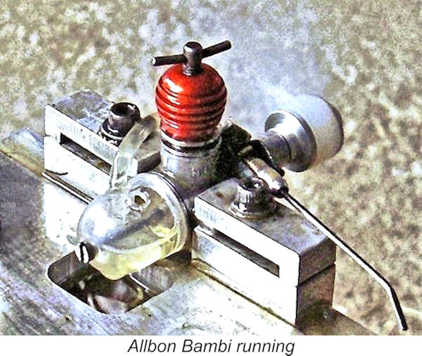
Mind you, curiosity has led me to run both models on the bench in the past, just to see how they handled and performed. While writing this article in 2026, I repeated the exercise, trying examples of both models to refresh my impressions. The little AE 0.1 cc diesel's radial mount makes it quite easy to arrange a test mounting on the end of a piece of round aluminium bar or similar. Like all sub-miniature beam mount diesels, the 0.2 cc AE is rather overwhelmed by a conventional test stand. Consequently, I've constructed my own miniature test stand for use with such engines. It works well with almost any small beam-mounted diesel of less than 0.5 cc. The accompanying image of an Allbon Bambi on test shows this stand very clearly.
The one comment that I would add is that these tiddlers really do benefit from the use of castor oil in the fuel - its extra viscosity and superior surface coating characteristics can make all the difference in promoting a good compression seal and freedom from any trace of leakage with these tiny engines, as well as enhancing their wear-resistance. The main challenge involved in starting is to prevent the engine from becoming flooded – all too easy to do with such small engines since so little excess fuel is required to create a flooding situation. The use of a suitably-sized syringe or flexible fuel bottle with a fine metal delivery tube will minimize any tendency to over-prime, besides which it will be found very helpful when filling the tiny tank.
The above technique works very dependably indeed once the settings have been established. However, establishing those settings in the first place can present a challenge in itself. Since the engines appear to have been test-run at the factory, the compression setting of a new example as supplied is probably somewhere near correct, while a used example will presumably have been left at its last running setting. Even so, it’s wise to begin with the compression backed off a little to allow for such potential issues as congealed castor oil residue taking up space in the tiny combustion chamber.
Eventually you’ll arrive at a setting at which the engine fires readily. However, it can’t keep going after the intake prime is burned off because there’s no fuel supply. So once you have a compression setting at which the engine will fire dependably, it’s time to initiate such a supply!
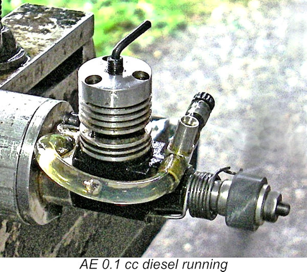
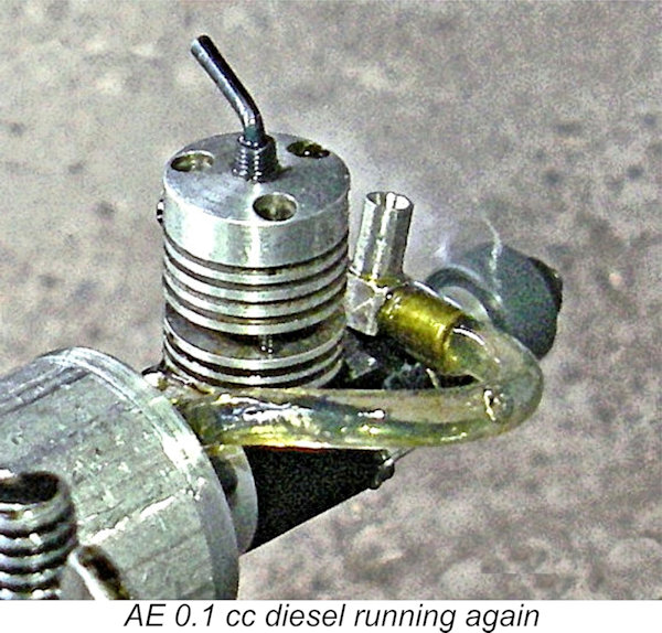
Now repeat the compression-setting exercise. Administer one drop of fuel into the intake, check that the engine turns smoothly over compression without undue resistance, and then activate the spring starter. Since you already established the compression setting, the engine should fire immediately. However, in all probability the needle setting will be too lean, in which case the engine will start briefly and then starve to a halt. Open the needle a quarter-turn and try again. Eventually a setting will be reached at which the engine keeps going once started. After that, it’s all quite familiar – just fine-tune the compression and needle valve in the usual way. I've actually found that the 0.2 cc model is perfectly straightforward to hand-start in the usual way, although the spring starter can of course be used if desired. By contrast, the tiny 0.1 cc version is definitely easier to start using the spring starter. I have succeeded in hand-starting it once or twice, but definitely find starting to be more dependable using the spring.
To avoid having to do all of this every time, make a note of the settings “just in case” and leave the engine as set in between runs. If the engine is to be stored un-run for any length of time, it’s wise to back-flush the fuel line with solvent to prevent the needle valve from becoming blocked with congealed castor oil. Also, the engine should be flushed with solvent and after-run mineral oil prior to storage - congealed castor oil deposits can play havoc with such small engines.
In stark contrast to my very positive experiences with this engine, I have to report that my good mate Maris Dislers found his example of the AE 0.1 almost impossible to start. He put this down to an excessive degree of bore taper allied to a poor needle valve design. Despite the positive experiences of Jim Woodside, John Robarts, the video guy and others (including myself), it's clear that sub-standard examples did make it out of the workshop. In the case of the AE.2, Maris Dislers' experiences were far more positive than those which bedeviled his AE.1 unit. His notes record easy starting with fuel of equal parts castor oil, ether and kerosene, with 0.8% ignition improver added, giving somewhat cooler running than fuel with 1.5% improver. Maris's cold-starting routine involved 2 drops of fuel into the venturi from the syringe, a light exhaust prime with piston closing the exhaust, and blowing away the excess. Then back off compression by ¼ turn. Needle set at 2¾ turns and it would go. Warm/hot restarts were accomplished on the running settings with only a one-drop venturi prime. The following prop/RPM figures were obtained.
The recorded torque around 0.9 oz-in is rather low when compared with small diesels of similar swept volume. Yet the engine holds this across the 9,000 to 12,000 bracket and does not lose much through to the indicated 0.012 BHP peak circa 14,000 RPM. The engine approaches its peak with the Cox 4½x2 airscrew, but Jim Woodside is probably correct in saying that a Graupner 5x2 is the more practical flying propeller choice. Maris's engine seemed to be “loaded” with anything larger. For my part, my example of the AE 0.2 cc model managed some 14,200 RPM on the Cox 4½x2 airscrew which was designed for the Pee Wee and Tee Dee .020 (0.33 cc) glow-plug motors. This seems to give me bragging rights! For comparison, the 0.15 cc Allbon Bambi which I tested for my article on that model only reached 10,000 RPM on that prop, although it got up to 11,400 RPM on the same prop cut down and trimmed to 4 in. diameter. My tested example of the 0.24 cc VT-11 from 1958 Hungary turned the same A video sequence of the 0.2 cc model running rather indifferently appears here. In that case, the operator never got to grips with the appropriate compression setting, keeping the engine woefully under-compressed for the most part and using a heavy-handed approach to adjustment rather than the gradual incremental approach which these engines require. The poor performance shown in this video is definitely not down to the engine, which hand-started easily, responded well to the needle and seemed anxious to give its best if only the operator would allow it to do so! Jim Woodside reckoned that while the cited Cox props were OK for bench running and running in, they don’t yield the best results in a flying situation due to the lower speeds achieved with the smaller-displacement AE diesels using these props, which were designed for operation at ultra-high speeds with their intended Cox Tee Dee glow-plug powerplants of somewhat larger displacements. Jim recommended using a Cox 4½x2 trimmed down to 3¾ in. diameter for best airborne performance with the 0.1 cc model. The 0.2 cc unit was apparently found to perform best in the air with a Graupner 5x2 airscrew, although the manufacturer recommended a Cox 5x3 cut down to 4 in. diameter. Jim’s recommended fuel mixture was 40% ether, 38% road diesel fuel (kerosene) 20% castor oil and 2% IPN cetane booster.
Back at the “bat cave”, Maris had more success using fuel containing equal parts castor oil, ether and kerosene, with 0.8% ignition improver added. The extra oil allowed better pumping action, although the engine still liked an exhaust prime for starting. Even so, the AE was less than easy to operate, especially with the 049 glow size six-inch propeller fitted. Previous experience suggested that the AE.5 is essentially a low-revving engine. That means a 7x4 propeller, or perhaps a 7x3 if you really want it chirping, and the extra flywheel effect greatly assists starting. However, the engine just would not catch on after the initial prime was consumed, unless the needle was opened well out from running spot.
Once running, the engine proved to be very insensitive to adjustment. Unless absolute peak power is needed, it appears to be wise to take advantage of the AE’s ability to run happily on a wide range of somewhat rich mixture settings. With a little experimentation, a balance between running and restarting settings can give very easy handling, without too much speeding up as the last of the fuel is used up. Speed adjustment is taken care of by the compression screw, which has a very positive effect down to a nice tick-over at 4,200 RPM. At the top end, the following prop/RPM data were eventually obtained.
The above test results, demonstrate that the AE.5 differs from the higher revving Allbon/D-C Dart or PAW 55’s, which peak at 12,000 RPM and 18,000 RPM respectively. This doesn’t mean that the AE isn’t up to a bit of work. Because maximum torque and peak BHP are quite close together on the RPM scale, it delivers decent horsepower with real authority in a comfy zone between 7,000 and 10,000 RPM. Actually, 4.5 oz-in torque and 0.04 BHP more than adequately justifies the engine’s sturdy 49.4g (1.74 oz) weight among the useful point fives. So after these simple mods, Maris considered that this “tuned” AE.5 had joined the happy sport FF diesel engine ranks. Unfortunately, the problems with this example of the AE.5 were not confined to the needle valve issue. Maris found subsequently that the engine's crankshaft had cracked at the valve port - this after a run time of less than 30 minutes. This problem could have been a legacy of the tender mercies of its previous owner, who did not treat his diesels very well. Regardless, an additional factor was found to be the fact that some 20% of the bearing area on one side towards the rear had not been reached by the honing operation - a clear manufacturing deficiency.
The sole AE model to undergo a full bench test was the AE 25 BB of mid-1993. Dick Roberts’ report appeared very promptly in the August 1993 issue of “Aeromodeller”. Dick was very complimentary regarding this unit, characterizing it as “a nicely-made engine, easy to start and handle”. He praised the effectiveness of the matching silencer, also sharing his understanding from others that the accessory throttle worked very well, although he didn’t test it himself. He acknowledged that the AE 25 BB was “by no means a racer”, but considered it to be “very suitable for sport and scale models”. He felt that it should deliver a long working life, particularly if used with larger props. Although Dick didn’t publish any power output figures, he did provide a table of speeds achieved with a range of APC props for which power absorption coefficients are reliably known. This table is reproduced here for reference. Although Dick seems to have missed a few settings, these imply a peak output of somewhere around 0.265 BHP @ 13,500 RPM.
Set up in the test stand with an APC 8x6 prop fitted, the engine felt superb when flicked over. I filled the tank with a 40/35/25 kerosene/ether/castor oil fuel mix to which I added 1½% cetane booster, after which I was ready to go. It turned out that finger-choking alone was ineffective in preparing the engine for a start - a few drops of fuel down the intake and a small exhaust prime on a full fuel line proved to be the way to go. Using that approach, the engine proved to be a very easy starter. Running qualities were very good indeed. Response to both controls was both positive and progressive, making the establishment of the optimal settings very straightforward. The engine held a steady speed once set, with no trace of a misfire and no tendency to sag. I did notice what appeared to be a slightly higher level of vibration than ideal as the speed climbed past 13,000 RPM or thereabouts, but this is probably of little consequence given the fact that the engine turned out to develop its peak output at a speed below 13,000 RPM. The only other issue which presented itself was a tendency for the compression screw to unwind at the higher speeds. This was probably a characteristic of this particular example of the engine, which undoubtedly has a somewhat loosely-fitted contra-piston, as noted earlier. It's also likely related to the high-speed vibration issue noted earlier. Up to 12,500 RPM, the comp screw held its setting well. Even so, if I was planning to use the engine in a model, I'd fit a compression locking lever just to be sure. The following prop/RPM figures were measured during the course of this test:
As can be seen, this engine proved to be an unusually high-torque unit, developing outstanding power for its type and displacement at relatively modest speeds. It seemed to achieve a peak output of around 0.201 BHP @ 12,300 RPM. The peak appeared to be relatively flat - the engine was developing 0.180 BHP or more at all speeds between 11,000 and 13,200 RPM. This is a more than acceptable sports performance for a plain bearing 1.5 cc diesel. Coupled with its very easy handling, the AE 1.5 cc diesel would undoubtedly have given full satisfaction to any user having realistic performance expectations and intending to use it in the sport-flying context for which it was undoubtedly designed. That said, this model too was not without its potential problems. Maris Dislers reported that his example of the AE15 had succumbed to a loosening of the pressed-in crankpin - clearly an assembly error. Maris appears to have had relatively poor luck with these engines! However, his experiences confirm that the production capabilities of Allen Engineering appear to have been somewhat strained by the demands placed upon them by the manufacture of these engines - a proportion of them seem to have escaped the workshop harbouring some quite significant defects. Conclusion The AE range constituted a fitting swan-song to the long career of one of Britain’s most notable model engine designers and manufacturers, Dennis Allen. For the most part, they were well-designed units which were constructed to good standards and delivered a fully satisfactory sports diesel performance. A good example also handled very well - even the tiny 0.1 cc and 0.2 cc models can be far easier to operate than commonly thought. I think that Maris Dislers summed it up very well when he commented that he saw the entire AE range as a brave exercise in applying then-new CNC machining capabilities to making model engines so that minimal tooling up was required and they could be manufactured in quantity with the limited equipment available. For the most part, this exercise was a success. However, the quality of the engines appears not to have met the standards of consistency to which Dennis Allen may have aspired. One gets the impression that the designs could have benefited from more prototype development and testing prior to release, in which case a few of the issues mentioned above might have been avoided. Even so, I personally view the AE range as a worthy sign-off from a remarkably talented individual! __________________________ Article © Adrian C. Duncan, Coquitlam, British Columbia, Canada First published August 2026 Revised September 2026 - Maris Dislers' test results |
||
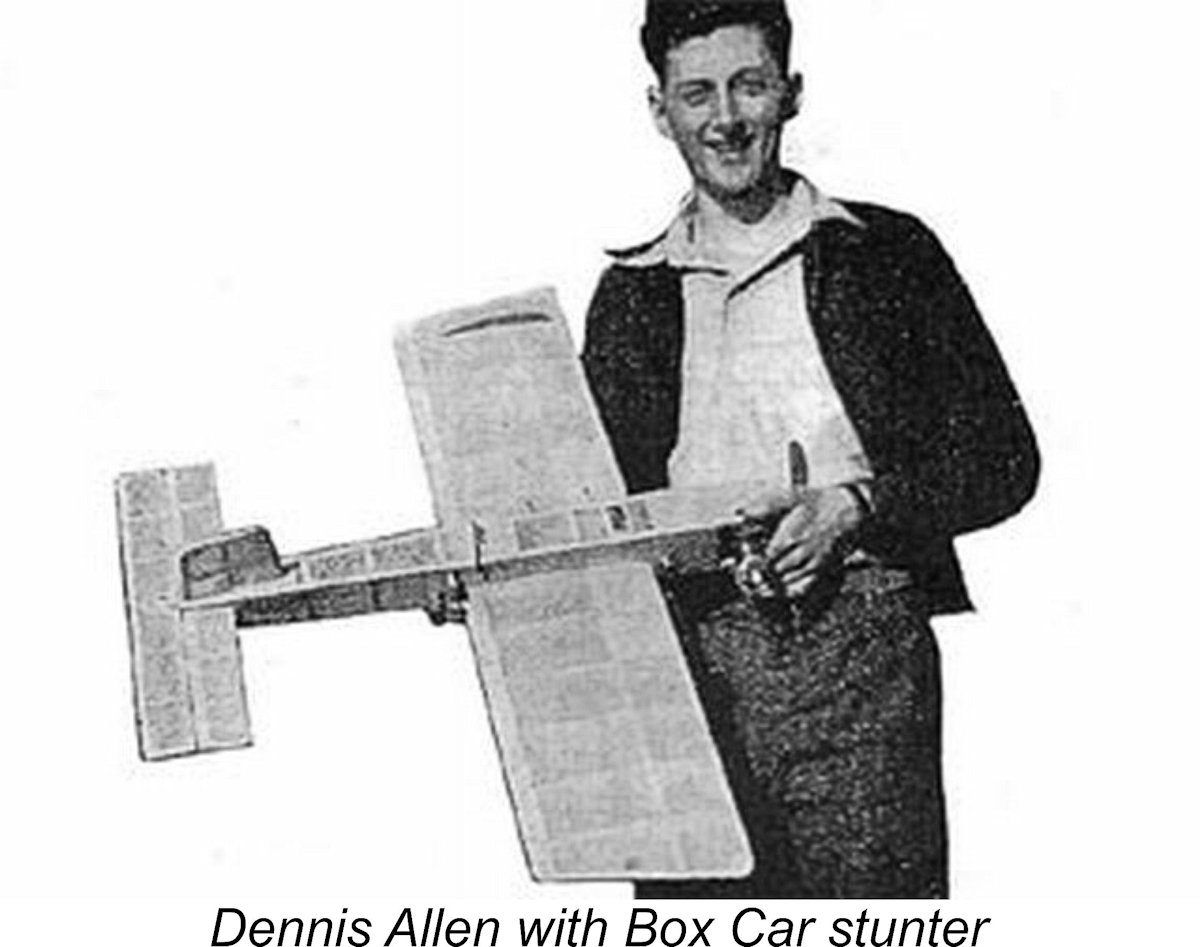
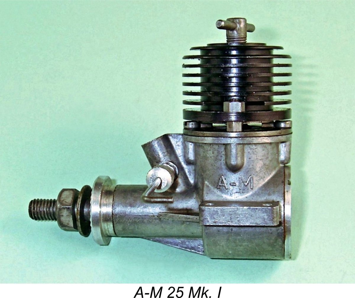 Dennis Allen’s early experience included working for Henry J. Nicholls as his engine repair wizard at the famous "308" shop. He subsequently spent time working on the
 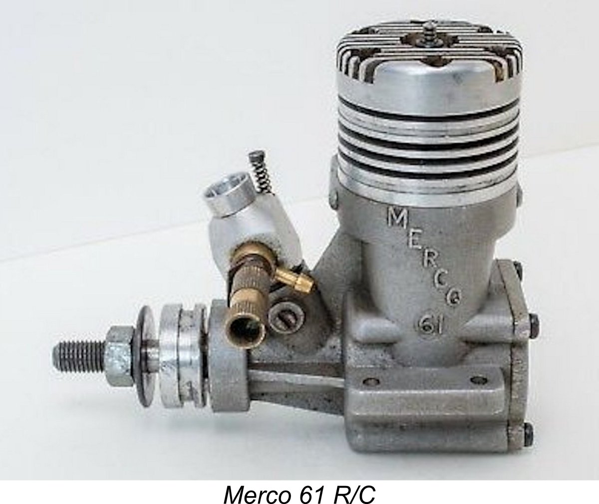 this takeover from a business standpoint was amply demonstrated by ongoing sales trends. By 1962 the mid-sized and larger R/C glow-plug motor was well and truly in the ascendant, with the market for smaller diesels and control line engines in general now beginning to shrink perceptibly. As time went on, the MERCO R/C engines increasingly came to dominate the sales picture for the company.
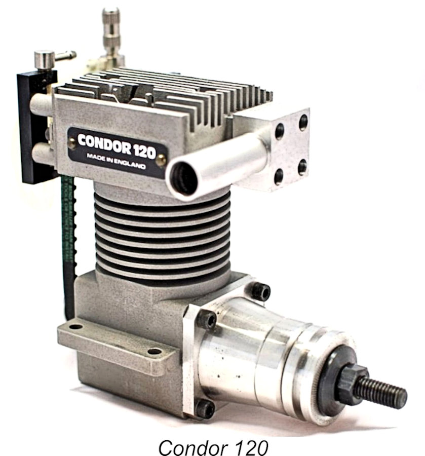 Following his break with the company that he had started, Dennis Allen spent some years producing glow-plugs, an activity which he had initiated during his involvement with the A-M range in conjunction with the 1959 introduction of the rather unsuccessful
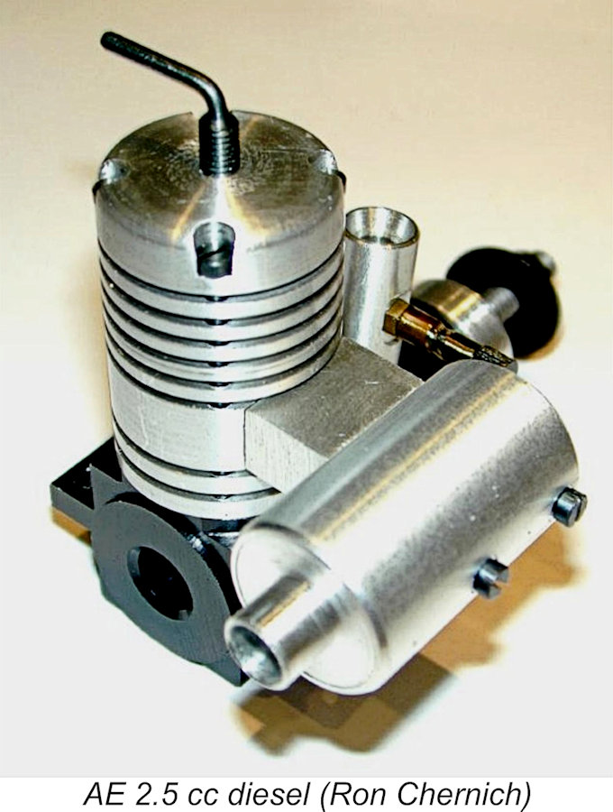
 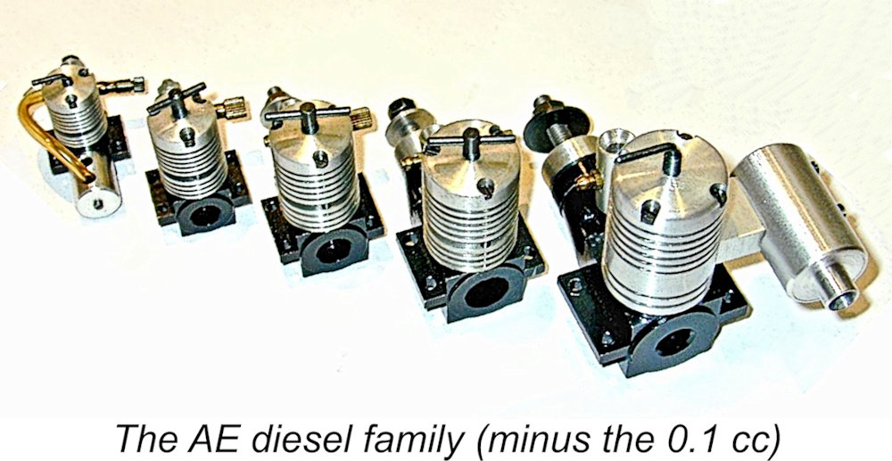 The AE engines departed from normal series-production methods by using no castings, the crankcases being milled from bar stock and finished with a black anodizing treatment. The range comprised engines having displacements which ranged all the way from 0.1 cc through 0.2 cc, 0.5 cc, 1.0 cc and 1.5 cc up to 2.5 cc. All were built to a generally similar design, albeit with some detail differences between models (the 0.1 cc model is missing from Ron Chernich's accompanying image). The engines were distributed both in the UK and abroad through Irvine Engines.
 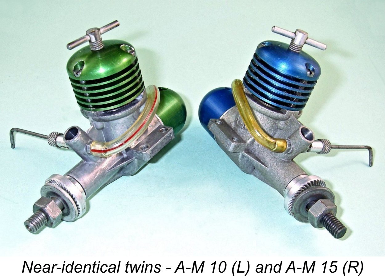 Like Dennis Allen's earlier A-M series, the engines are identified as "AE" products with a suffix formed by multiplying the displacement in cc's by 10. Dennis stuck with the convention established by the earlier Allen-Mercury series whereby the A-M 25 was nominally a 2.5 cc engine, not a 0.25 cuin. (4.1 cc) unit, the A-M 15 was a 1.5 cc design, and so on. Similarly, the AE 25 was a 2.5 cc model. However, the matter is rather confused by the fact that the AE engines below 1 cc were not the AE 1, AE 2, and AE 5 as would be expected if the same protocol was followed, but "AE .1", "AE .2", and "AE .5". A certain lack of consistency there ............
 The first AE model to reach the market was evidently the 1.5 cc AE 15, which was to prove to be the longest-surviving member of the AE range. This model began appearing in dealer advertisements in June 1987, dating its market debut quite securely to around May 1987. The first listing of the 1 cc model appeared a year later in June 1988, with the 0.5 cc model showing up initially in February 1989. It’s clear that the development of other models was well in hand by this time. In April 1989 the little 0.2 cc model made an initial advertising appearance, as did R/C versions of the 10 and 15 units. The “Motor Mart” feature in the May 1989 issue of “Aeromodeller” included a photo of three of the AE designs released to date – the .5, 10 and 15 models – together with two prototype units of larger displacement. Although it had been released by this time, the little 0.2 cc model had evidently not reached the hands of the magazine’s writers in time to be included.
 By May 1990 the 0.2 cc AE .2 was deemed worthy of being covered in some detail in the “Motor Mart” feature for that month. Development was still continuing, with a Mk. II version of the 0.5 cc AE .5 appearing in dealer listings for the first time during the same month. This variant featured a modified needle valve, a spring starter and a tank.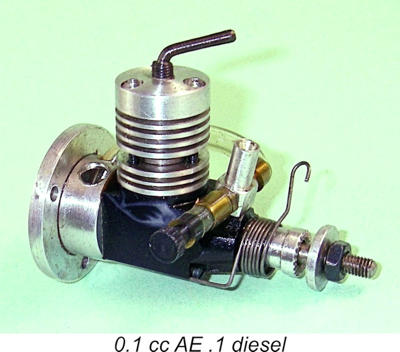
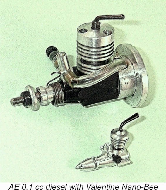 The truly remarkable Ronald Valentine sub-miniatures of even smaller displacements were really individually-crafted custom productions as opposed to series production models like the AE .1. Nonetheless, they demonstrated that even the tiny AE offering was only hinting at the lower displacement limit to which a model diesel could be constructed. The accompanying image of an AE 0.1 cc diesel with Ronald's truly amazing 0.006 cc (!!) Nano-Bee makes this point very clearly! However, the level of individual precision required to construct such an engine successfully is such that series production could never be viewed as an economically viable proposition.
  both the AE.1 and AE.2 midgets. Those tiny engines clearly created a great deal of interest in Dennis Allen and his creations.
  As matters transpired, the AE range proved to have reached its fullest extent with the introduction of the 2.5 cc AE 25 BB. Production of the full range continued at least until the latter part of 1994, when the last advertisement placed in “Aeromodeller” by Michael’s Models in October 1994 featured the entire range, including the 0.5 cc AE .5. It was after this date that Michael’s Models became Engines Unlimited.
 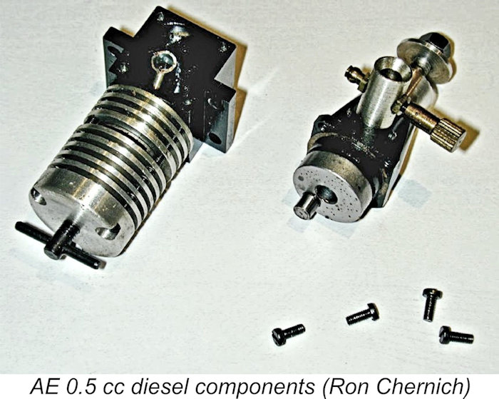 At first, the AE engines look to be very simple designs, which indeed they are. However, close examination through disassembly shows clear evidence of Dennis Allen's many years of design and manufacturing experience.
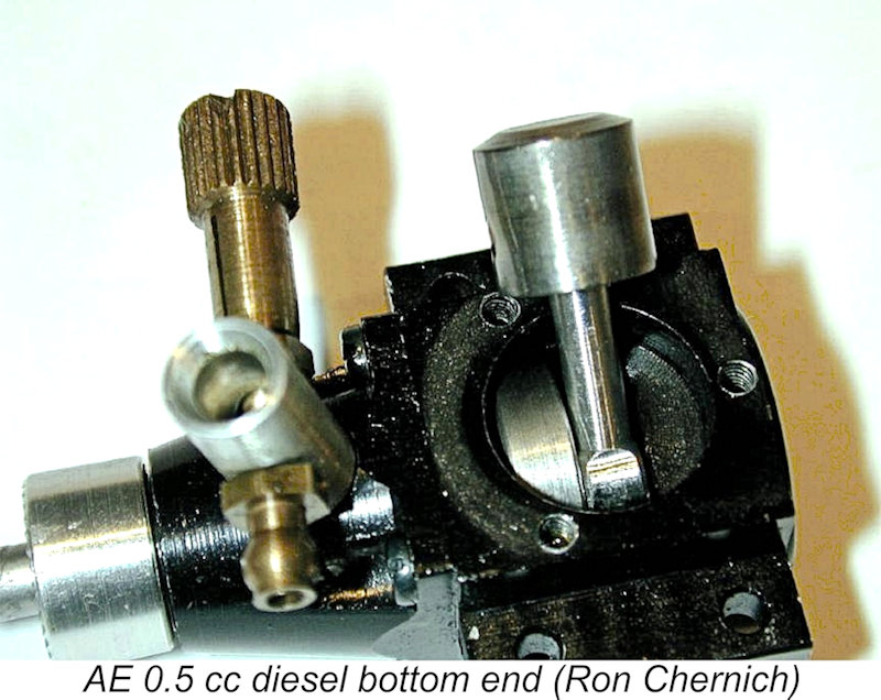 spray bar assembly used on the AE .5, AE 10, and AE 15 is a conventional design with a split thimble, a one-piece spraybar and a single jet hole, while the two smallest engines (the AE .1 and AE .2) and the AE 25 all use two-piece spraybars. The turned and knurled prop-driver is pressed onto knurled splines on the front of the crankshaft, rather discouraging disassembly to see if there’s any shaft bushing (there isn’t).
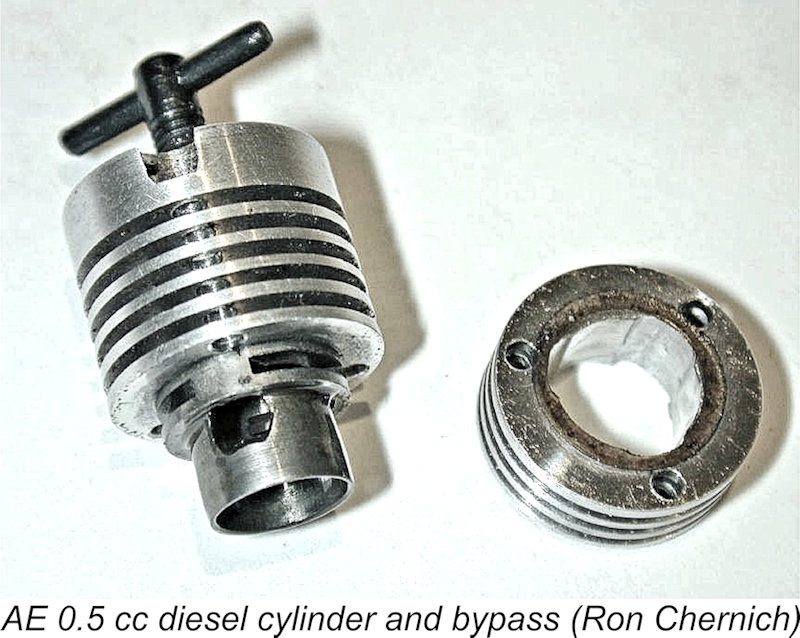 On all but the 2.5 cc model, the cylinder is attached with three long screws. These are cheese-headed and finished to an attractive "blue" colour, apparently by heating. The liner is from steel and has a thick flange into which the three exhaust slits are cut on a 120º radial spacing. The inter-exhaust "posts" are large, allowing the transfer ports to be milled at an angle to overlap the exhausts, assisting gas flow and reducing the blow-down period between exhaust and transfer opening. The overlap also increases the transfer duration while reducing the distance that the piston must descend below the bottom of the exhaust ports, thus increasing the proportion of the power stroke during which the exhaust ports are closed and combustion pressure is applied to the piston. Good for torque development .........
 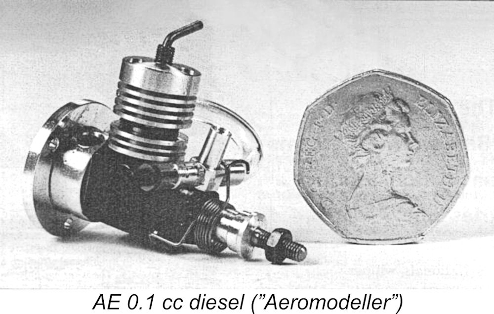 At the bottom end of the displacement scale is the 0.1 cc model (0.006 cuin.). Unlike the others, this one is radially mounted using the flange which covers the rear of the tiny integral fuel tank. A great deal can be learned about this engine by watching
  The act of winding the spring starter requires that the engine be turned slowly backwards over compression, which will reveal any lock or near-lock condition before any attempt is made to start the engine. Moreover, the use of a spring of suitable torque limits the amount of force which can be applied to the components. So if the engine is in a hydraulic lock, the spring will simply fail to carry it over compression, with no harm done – it won’t force it. On the other hand, the Bambi-style “team race clobber” can exert excessive levels of stress on the tiny components if the engine becomes flooded, as can easily occur with very small engines. Use of an electric starter on the little ‘uns is effectively a death sentence - I’ve seen more than a few victims of this kind of abuse. My advice when running any very small diesel is – if a spring starter is available, use it!
 As a significant side-benefit, the tubing provides an effective seal against air-leaks, which can spell doom to any chance of obtaining reliable running at the miniscule mixture supply ranges required by these tiny engines. It also helps to stabilize the needle laterally in its threads. There is naturally a down-side, which we'll discuss later.
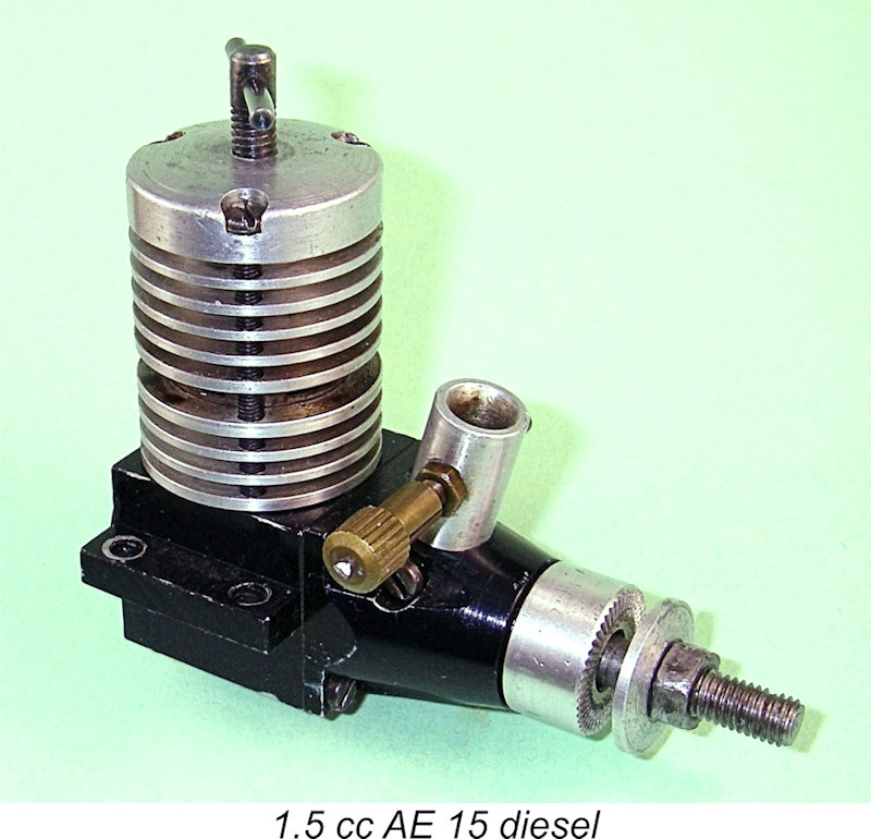
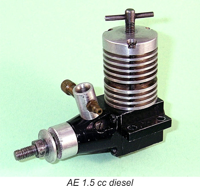 The 0.5, 1.0 and 1.5 cc models are all very similar, both in construction and in external appearance. All three of these models lack back tanks. None of them features a spring starter, while all three utilize a conventional needle valve with a split thimble and a one-piece transverse spraybar. The photo here shows the 1.5 cc engine, although you'd never be able to identify the model from the photo alone since the engines in the AE range carry no external markings whatsoever, while the designs are vitually identical - just executed at different scales.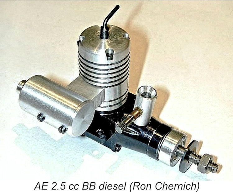
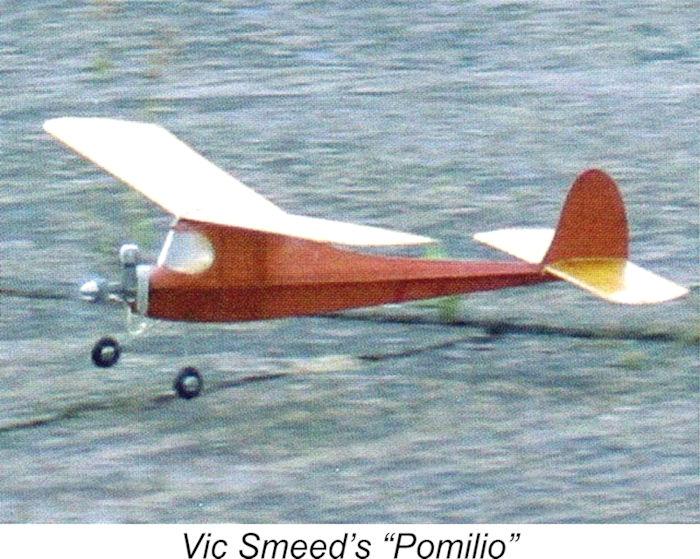 the AE .2, but hard upon the heels of the appearance of the tiny 0.1 cc model, which doubtless aroused a good measure of curiosity. Author John Robarts confined himself to a description of the two engines, his only performance-related comment being that once properly adjusted they both ran "sweetly".
  Speaking personally, I confess to holding the view that horsepower and torque figures are pretty much irrelevant when it gets down to engines of this size. The only meaningful test which I see as being applicable is whether or not the engines develop sufficient levels of performance to fly a model. Jim Woodside’s experiences show that this is definitely true of both the AE .1 and AE .2 models. That’s good enough for me!
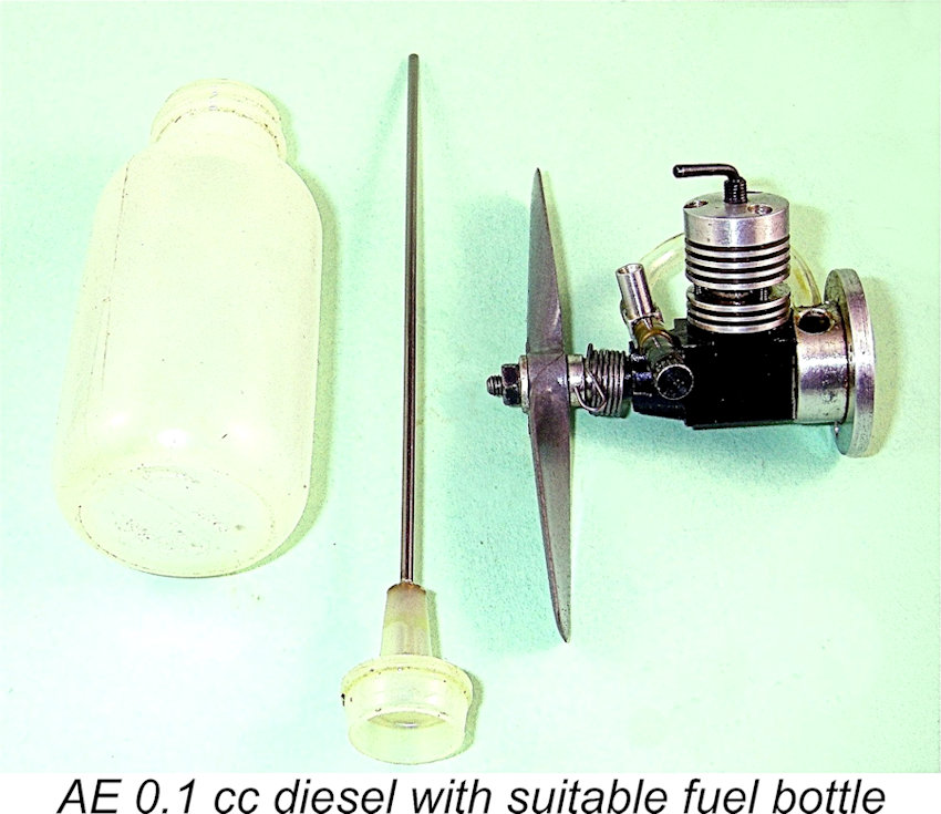 As a general rule of thumb, it’s advisable to use a fuel containing at least 40% ether when running any really small diesel – they tend to start much better and flood less readily using such a fuel. Jim Woodside made a particular point of this recommendation in his 1994 report. Using such a fuel together with the spring starter, I've found that both models start very readily once the correct settings have been established. In fact, I've had good success starting and running both models on standard diesel fuel having a "normal" amount of ether. They are actually less fuel-sensitive than earlier reports might suggest.
  I’ve found it to be wise to steer well clear of administering an exhaust port prime, even a "dry" one, since this almost invariably results in a hydraulic lock. A far better approach is to choke to fill the fuel line (and no more), then inject a single drop of fuel into the intake. If the settings are anywhere near correct, this usually produces a start within one or two activations of the spring starter. Once you get to know them, these little engines are far easier to handle than their reputation might suggest!
  If the settings have been lost or altered during storage or as a result of "fiddling", my recommendation with any diesel having such a small displacement is to adopt a methodical two-stage approach to the initial start – first establish the compression setting, and then determine the appropriate needle setting. To do this, I always begin with no fuel in the tank and the needle valve closed. In this condition, inadvertent flooding of the engine is highly unlikely – one less potentially harmful possibility to worry about! Using a suitable syringe or fine-tube fuel bottle (which will be necessary later for filling the tank), administer a single-drop intake prime, check that the engine turns over compression without undue resistance and then activate the spring starter. If the engine doesn’t fire after two or three attempts, increase compression a little and try again. After 4 or 5 starter activations, it will probably be necessary to administer another single-drop intake prime - you need at least some fuel in the cylinder!
  In searching for the appropriate needle setting, it’s always best to begin from the lean side, since inadvertent flooding is far less likely on a lean needle. I generally close the needle completely and then open it one turn. Fill the tank using a suitable syringe or bottle, finger-choke the intake and turn the prop slowly on the compression stroke until crankcase suction just fills the fuel line. This confirms two things – one, the crankcase seal is good (otherwise no suction); and two, the needle valve is clear and open sufficiently to pass at least a little fuel. So far, so good ……..
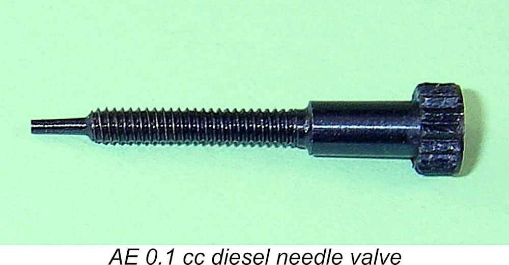 A problem which bedevils the AE 0.1 in particular (but also the 0.2 to some extent) is that the externally-threaded needle tends to be a little loose in its thread, to the point that lateral pressure on the control disc can affect the setting even without turning the control. The fuel tubing tensioner stabilizes the needle to a large extent, but even so setting consistency is a bit shaky. Make needle adjustments in very small increments, since the engines are extremely sensitive to that setting. Also, assess the effect of any change with the fingers removed from the control. Once a good setting is established, be thankful and leave it alone! It must be said that this needle valve design appears to be somewhat flawed - an engine this small really needs a high-precision fuel metering set-up, which this isn't.
 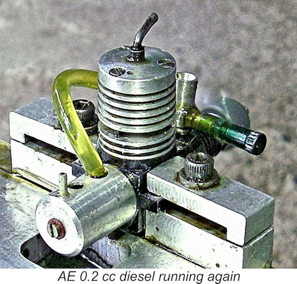 On the bench, my test example of the 0.1 cc midget spun a Cox 3x1¼ Tee Dee .010 prop at just over 18,000 RPM. While seemingly quite impressive, this figure is well short of the 27,000 RPM at which a typical example of the 66% greater capacity Cox Tee Dee .010 glow-plug unit spins that prop. I have no idea what kind of power output is represented by the AE's 18,000 RPM figure, but consider that to be irrelevant in a case such as this. The tiny fuel tank has sufficient capacity to provide a leaned-out run of just over a minute - ample running time for free flight purposes.
 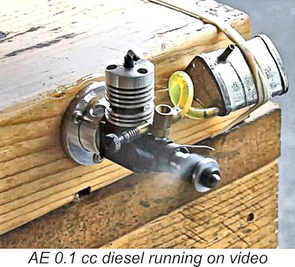 A good video of an AE .1 running very well may be found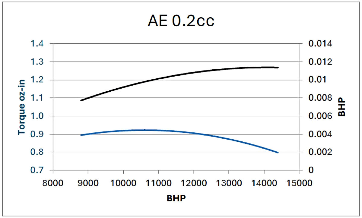
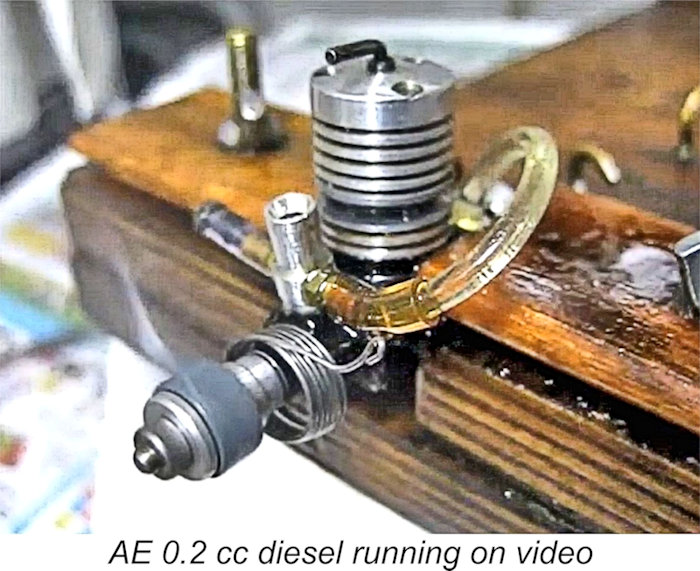 4½x2 prop at 13,000 RPM. My example of the AE .2 is clearly a very good performer for its displacement! However, it does underscore the undeniable fact that the performance of these engines between one example and another may be quite variable.
 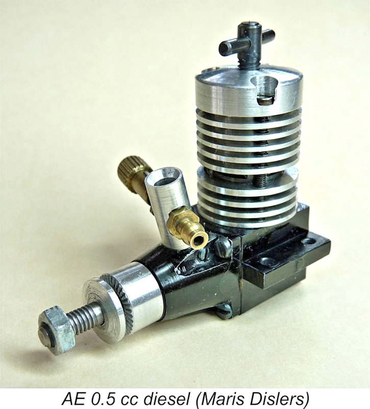 The next model up the displacement scale was the 0.5 cc AE.5. This was never the subject of a published test, but Maris Dislers once again conducted his own test. His test example had come to him from an original owner who couldn't
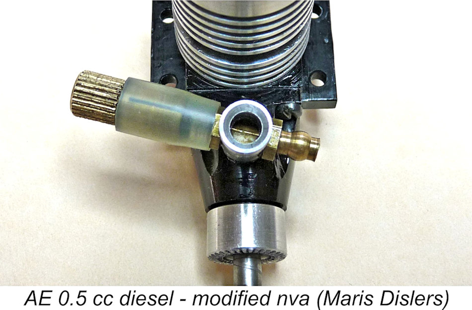 A closer look gave the clue. The choke area of a touch over 3 mm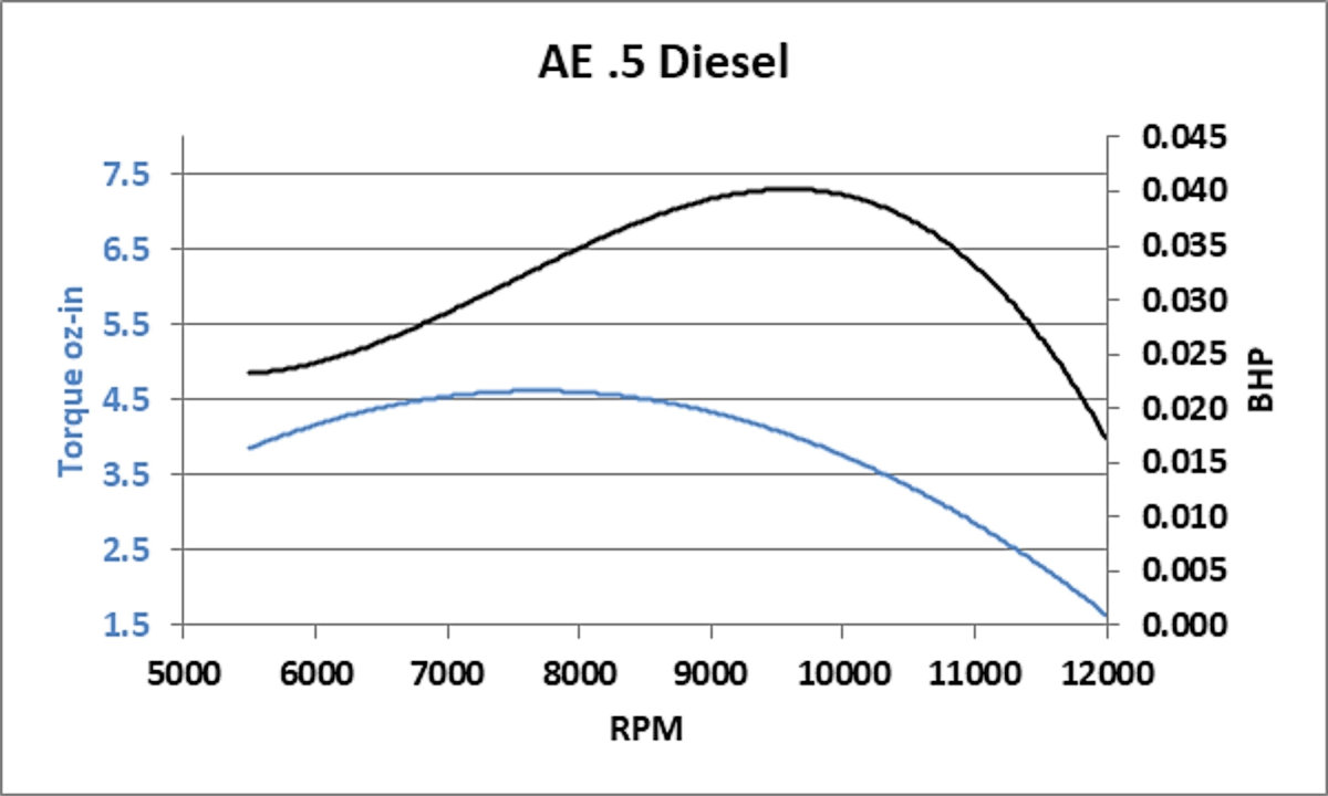
 On closer inspection, the crankshaft was found to have a 4 mm gas passage in a 6 mm shaft journal along with what appeared to be an excessively large intake port which opened soon after BDC and closed around 40 degrees after TDC. Along with the very generous choke areas, these characteristics imply that Dennis Allen expected this engine to be a screamer. If that was the expectation, he was sorely disappointed! As Maris's performance curves show, power was found to peak at around 10,000 RPM with a quite rapid drop-off beyond that.
 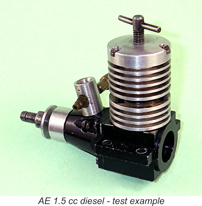 The 0.5 cc, 1.0 cc and 1.5 cc AE models were never subjected to a published test or even a detailed product review. I don’t have examples of the 0.5 cc and 1.0 cc units, but I do have a couple of examples of the 1.5 cc variant which got the AE range started in 1987. This being the case, I saw it as being worthwhile to put that model through a full bench test. I chose the least pristine of my two examples, since it has lost its box and has clearly seen a fair bit of previous use in a model. Despite bearing the visible evidence of this earlier use, the engine remains in excellent mechanical condition with outstanding compression and perfectly-fitting bearings, its only flaw being a contra-piston which seems by feel to be slightly looser than ideal.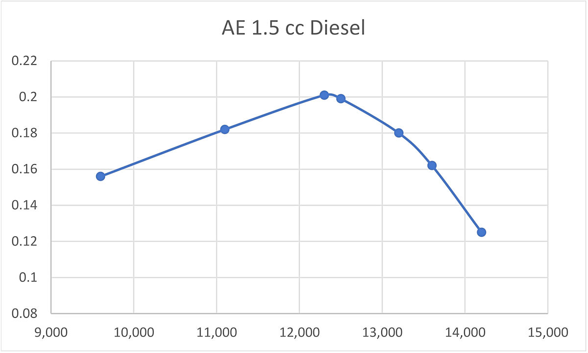
| |