
|
|
Rare Orientals - The TOP Engines
My initial study of these engines and their background led to the August 2011 publication of the original version of this article on the late Ron Chernich’s “Model Engine News” (MEN) website. So why the article’s re-publication here? Mainly because my mate Ron left us in early 2014 without sharing the access codes for his heavily-encrypted site. Because no maintenance has since been possible, the MEN site is slowly but perceptibly deteriorating as the various links fail progressively - an inevitable process which can have only one ending in the long run. Since it still appears to be the only published source of information in English on the TOP range, I was unwilling to risk the loss of reader access to the information, hence the article’s re-publication here. An exhaustive search of the English-language modelling literature from the early post-war period during which the TOP engines were unquestionably being manufactured has turned up not a single reference to the range. This is entirely understandable since although there was a thriving power modelling scene in both pre-war and post-war Japan, language and political barriers combined to render this invisible and hence unreported to the outside world. It was not until the mid-1950's that the English-speaking modelling media began to take sufficient interest in the products of the post-war Japanese model engine manufacturing industry to begin documenting them on a regular basis. By that time, the TOP range was already long gone. It's thus completely unsurprising to find that the TOP marque appears to be almost forgotten today, even by quite a few folks who are genuinely interested in classic model engines. When first researching this topic in 2010, I discovered that only a handful of my fellow aficionados had so much as heard of this range! This is not a desirable situation - if these engines are to be preserved, interest in them must be sustained through an effort being made to draw aside the veil that has hitherto concealed them.
In that regard, I'd like to begin by acknowledging my considerable debt to Alan Strutt of England for his assistance in facilitating my acquisition of a number of the TOP engines on which this study is based as well as his sharing of information in his possession. Alan also read the initial draft of this article and provided numerous helpful comments and suggestions. In many ways, this article should be viewed as a collaboration rather than as my own work. That said, I accept full responsibility for any errors or omissions which may appear in the following text. Sincere thanks are also due to my English friend Mel Reid for his invaluable assistance in deciphering some of the Japanese script from which I’ve been able to draw a number of conclusions. Mel also helped greatly in the search for corporate information on Google Japan. The next section will summarize what little has been learned to date about the TOP range in general. This will doubtless suffice for many readers. However, for those interested, subsequent sections will present further details of a few specific TOP models for which authoritative information is available. The TOP Range - a Summary It has long been a common practice among Western model engine manufacturers to name their products after tangible things - often animals or weapons - that the maker sees as best representing the attributes of the item being produced. This was done in an endeavor to encourage the buyer to own such a powerfully-endowed product. In a model engine context, names like “K” Vulture, KeilKraft Cobra, FROG Viper, Oliver Tiger, D-C Wildcat, E.D. Hornet, D-C Rapier, D-C Sabre, Allbon Javelin and Allbon Arrow come immediately to mind, and there are others.
A translation of the Japanese characters on the box label of a TOP “A” glow-plug engine in my possession reveals that the TOP engines were made in Osaka, Japan at a facility known as the Sumiya Works. The box also announces that the firm made "all kinds of gas engines". The name Sumiya seems to be fairly common - there are a lot of Japanese businesses called Sumiya Something-or-other.
Overall, this presents the presently-unsubstantiated possibility that the engines may have been manufactured by a family called Sumitani at a workshop in Osaka called the Sumiya Works - the term "ya" at the end of a Japanese name generally equates to "shop" or "place of business". Accordingly, the Sumiya works could well be the "place of business of the Sumitani family". Such a grass-roots workshop origin would certainly mirror the establishment of many other Japanese model engine manufacturers. The fact that the name is rendered on the engines in Katakana characters strongly implies that it is used here as a commercial trade-name rather than a family name, since Katakana script is used almost exclusively to render imported words or commercial terms. Even so, there is nothing to suggest that the trade-name could not have been derived from a family name. It would be entirely consistent with established Japanese practise to name the company after the founding family but render it in Katakana to denote the fact that it is being applied to a commercial venture. A further search on Google Japan in 2011 threw up several companies trading as of that year under the Sumitani name. It seemed almost too much to hope that the company that made the TOP engines would still be in existence as of 2011, but one likely candidate did in fact present itself in the shape of the Sumitani Corporation. This was a major conglomerate engaged in the manufacture of both chemicals and engineering products. Their web-site was all in Japanese and was both extensive and complicated - one would have needed to be a fluent Japanese reader to get much from it.
Since the TOP model engine range seems to have disappeared from the market in 1951 or thereabouts, I can state with confidence that the then-new Sumitaniya company which later became the Sumitani Corporation was founded in the right place, in the right line of business (precision engineering), at the right time, under the right name and using the right logo to have been a direct successor to the original Sumitani engine-manufacturing venture which made the TOP engines. However, that's as far as I can go at the moment - I can’t claim this connection as an established fact
Whatever the truth, Mr. Haruyama continued to be involved with model engine manufacture long after the demise of the TOP brand. Apart from producing further models under the Haru label, he was associated with the Sky Shark 49 design of the early 1950's and the Sky Queen engines of the late 1950's and early 1960's. The issue of dating of the early TOP engines is somewhat problematic and perhaps a little controversial. My Japanese sources have consistently cited dates as early as 1940 for the introduction of the TOP range, offering the engines for sale on eBay with such dates attached. They have been quite definite that the engines were in existence by 1941. Others like Mike Clanford (in his enjoyable but frequently unreliable A-Z book) have accepted this dating without question, and it can't be denied that on purely design and architectural grounds it's certainly possible. However, there are several indisputable facts which argue quite persuasively against this dating.
A further characteristic which argues strongly against a pre-war date is the fact that all presently-known examples of the TOP spark ignition engines use ¼-32 threaded spark plugs. While such plugs were undoubtedly introduced before WW2, their use was very limited, even in the United States where they originated. Indeed, neither Alan Strutt nor I are aware of any pre-war European or Japanese engine that was originally supplied with this size of plug. Accordingly, if the TOP engines as we see them today were in fact introduced prior to Japan's entry into WW2, their use of the ¼-32 plug would make them unique among pre-war Japanese engines and highly unusual in world-wide terms. Without exception, all other pre-war Japanese spark ignition engines of Alan Strutt's extensive acquaintance were fitted with either 10 mm or 3/8-24 threaded plugs, and indeed these plug sizes continued to be widely used in post-war Japanese engines up to 1949, even after the introduction of the glow-plug. In fairness to my Japanese colleagues, I have to admit the possibility that there were examples of what they consider to be TOP engines produced before WW2 that did not carry Latin characters and used the larger plugs. But even if this is so, Alan and I were in agreement that any TOP engine displaying the name in Latin characters and having a ¼-32 plug must objectively be viewed as highly unlikely to be a pre-war product. Since I’m unaware of any examples that do not exhibit these features, the pre-war existence of the range by whatever name must be considered as unsubstantiated at the present time. Speaking strictly for myself, it would take the production of documentary or other hard evidence to convince me that this conclusion should be revised.
An interesting claim arose in connection with a 2010 eBay listing of the incomplete engine above at the right suggesting that there may have been a significantly smaller model offered at the same time. The seller did not identify the engine in question, but it undeniably displayed design features which were parallel to those seen in the various TOP models. The purchaser subsequently claimed that this engine is a TOP .049, although I never saw any actual evidence confirming this claim. In reality, it's my considered opinion that it was made by Mr. N. Haruyama, later manufacturer of the Haru range as well as the Sky Shark and Sky Queen engines. I have a couple of early piston-valve Haruyama engines, one of which resembles the eBay motor far too closely to be coincidental. The accompanying comparison image should demonstrate the point quite adequately. The lower engine in the image is clearly stamped with Haruyama's name, making its identification quite secure. At first sight, the claimed displacement of the eBay engine would appear objectively questionable based upon the fact that the .049 displacement category did not achieve any meaningful status until 1949. Moreover, engines of such small displacements were never really a practicable commercial proposition during the spark-ignition era given the disproportionate weight penalty relative to power output imposed by the ancillary ignition support equipment. The practicable lower displacement limit for commercial products was generally accepted as around 0.099 cuin. (1.62 cc) prior to the arrival of the diesel and glow-plug ignition systems. Both of my Haruyama engines are .097 cuin. models. However, the eBay engine's cited .049 displacement is undoubtedly at least credible. Scaling from the single presently-available image of the eBay engine using the Champion V3 plug as a dimensional standard implies a bore of around 10.0 mm. If the maker used the generally-fashionable slightly longer stroke in this engine, say around 10.5 mm, we would get a displacement of 0.824 cc (0.050 cuin.). These figures are of course totally unsubstantiated, but they do indicate that the purchaser's displacement claim cannot be ruled out. That said, I remain convinced that the eBay motor is a Haruyama creation rather than a TOP product. The above image confirms that it's a dead ringer for one of my Haruyama .097 models (which is complete with its tank and Atom-style "snap-action" timer). Mr. Haruyama is known to have made a few early .049 glow-plug motors, so why not an even earlier .049 sparkie? However, that's as far as I can go pending the receipt of further information. If this unit was indeed a Haruyama .049, then he may lay claim to having produced perhaps the earliest commercial model engine of that displacement to appear anywhere!
The working piston crown is provided with a sizeable central hole which serves as the transfer port. When pushed upwards by the conrod, the shuttle piston seats at the top against the underside of the working piston crown. The seating surfaces of both the shuttle piston crown and the underside rim of the working piston's central opening are chamfered at a matching angle exactly like a four-stroke valve and seat. Further upward movement of the rod naturally causes the two piston components to rise as a unit with the central opening tightly sealed.
The seal is maintained until the exhaust ports open during the power stroke, relieving the gas pressure above the piston. Even then, the inertial forces arising from the fact that the piston assembly is now rapidly decelerating as the crankpin swings towards the bottom of the stroke would keep the valve closed were it not for the fact that an internal ledge is provided at the top of the crankcase casting which limits the downward movement of the working piston. When its lower skirt However, the internal shuttle piston continues to follow the conrod by descending inside the working piston, thus opening the valve. Venting is provided to allow transfer gas to pass freely through the interior of the shuttle piston and thence through the hole in the crown of the working piston into the cylinder. As the rod and shuttle piston move past bottom dead centre and begin to move upwards on the compression stroke, the shuttle moves up within the working piston to first close the piston valve (making a further contribution to the "clatter") and then to cause the working piston to rise again with the valve now closed and ready to resist compression and combustion pressures. Thus the cycle is repeated. Complicated though it may sound, this system works remarkably well despite being mechanically ill-adapted to high speed running and creating a somewhat constricted transfer gas pathway along with a limited transfer period. The working piston is free to rotate within the bore, a factor which combines with the impact of repeated valve closures to maintain a good mating fit between the sealing surfaces of the shuttle and working pistons. In addition, the repeated passage of gas through the valve minimizes the build-up of foreign material in the sealing area as well as keeping the shuttle piston well cooled and lubricated. Finally, the presence of oil in the mixture protects the valve surfaces against wear and improves their sealing qualities. The use of a piston valve in the TOP engines night be taken to imply some kind of cross-fertilization between the USA and Japan either prior to the December 1941 onset of the two nations' hostile participation in WW2 or immediately following the cessation of hostilities in mid 1945. It's easy for some of us to forget that although WW2 had been raging in Europe and elsewhere for over two years prior to December 1941, there It's impossible to say at this point in time, over 70 years after the fact, in which of the two countries the piston valve principle was first applied to model engines. What is certain is that the year 1939 saw the introduction of two commercial model engines in the USA which used this principle. These were the Mighty Atom of .097 cuin displacement and the M&M "Piston Valve Motor" of .292 cuin displacement. The Mighty Atom was designed by the legendary Ray Arden and was manufactured by Microdyne Engines of Danbury, Connecticut. It proved to be a durable design, evolving into the popular series of Super Atom engines which survived in production into 1947 following a break during the war years. The piston valve system continued to be used throughout the production life of this design. The engines were noted as excellent performers in their displacement category.
This model does not appear to have been a great success, since it was replaced in the following year with a generally similar "High Speed" design of identical displacement which reverted to conventional porting while retaining the reed valve and other design features of its piston valve predecessor. Production seems to have ceased with the onset of WW2 and was never resumed thereafter. My sincere thanks to Tim Dannels for so ably summarizing the above information in his invaluable and highly recommended "American Model Engine Encyclopedia". The possibility certainly exists that the TOP designer had somehow heard about either the Mighty Atom or M&M designs (or both) and decided to give this principle a try himself. However, there is no proof of this one way or another, and it is of course equally possible that this was a case of independent parallel development.
What is less well-known is that in some early versions of these engines, such as the Gnome "Monosoupape" design, the pistons were fitted with pressure operated valves in their crowns. In practice it was found that the piston valves responded poorly to changes in altitude (not too clever in an aeroplane!) and were difficult to adjust, making field servicing a real pain. Accordingly, these valves were superseded by automatic by-pass valves somewhat akin to a 2-stroke bypass system. Nonetheless, the Japanese took an interest in Allied technical developments during the conflict, as a result of which they might well have known about the earlier piston-valved rotary engines used by their WW1 allies.
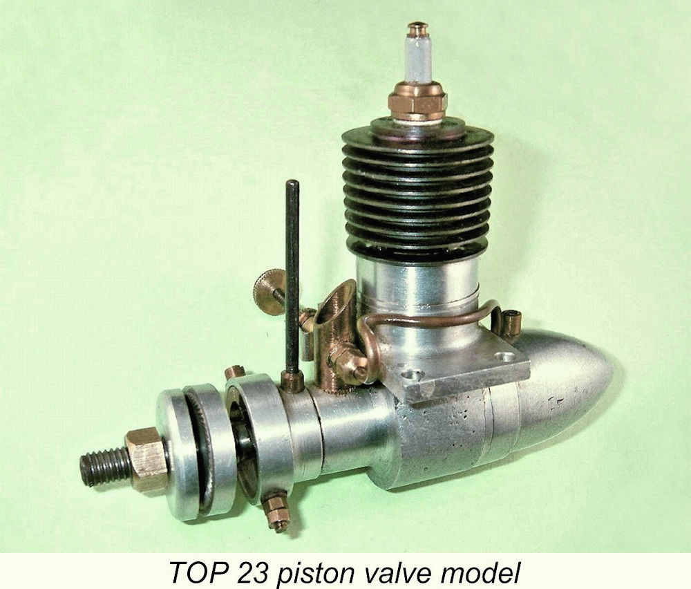
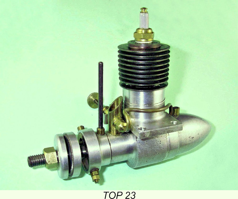
Both the TOP 19 and the TOP 23 were unusual in having both Japanese and Western script cartouches on the crankcase. In direct contrast to the pre-war situation, the use of Japanese characters in the early post-war years was somewhat remarkable given the fact that Japanese ciphers on commercial products were almost unheard-of during that period. Many of the products were intended for sale to Western customers, chiefly members of the Occupation Forces, at a time when the Japanese weren't exactly the flavor of the month. Consequently, most early post-war Japanese manufacturers fell over themselves adopting Anglicised names and ciphers. It is noteworthy in this context that the Japanese cartouche was omitted from some later examples of the TOP engines - my own late 23 model is such an example.
TOP carried on during this period, but by 1947 their piston valve engines had become out-dated and obsolete. The piston valve principle worked well enough in engines designed for low operating speeds, but at the higher speeds which modellers were then coming to expect the restricted gas pathway and mechanical complexity became severe performance liabilities. There is evidence that TOP responded to these challenges even while the spark ignition era was still in full swing. They certainly managed to produce one or two examples of a .60 cuin. rear disc valve spark ignition racing engine at around this time. As we saw in my companion article on the Super Hope 60, a surprising proportion of Japanese manufacturers of the early post-war period produced such engines in very small numbers, probably more as manufacturer's technical statements than for any other reason. The TOP 60 is almost never encountered today - I have only come across a reference to a single surviving example in Japan and don't have an image. The possibility also exists that TOP may have manufactured a conventionally-ported FRV .29 cuin spark ignition model during the same period. Alan Strutt confirmed the existence of such an engine which is claimed by its owner to be a TOP 29. I say "claimed" because although this engine reportedly bore some similarity to the earlier TOP 19/23's, also displaying features typical of early Haru engines, it was a conventional radially-ported FRV engine which does not bear the TOP name anywhere - merely the letter B, presumably to denote its displacement category, as well as a cartouche stamped into one mounting lug. This cartouche did not bear the TOP name in either Japanese or Latin characters, nor was the Sumitani cartouche present. If this engine is a TOP product, it would be the only known such product from the spark ignition era to display neither the TOP name nor the Sumitani designation. Accordingly, the identity of this engine must be viewed as an open question at this time - I merely mention it for completeness as a possibility. One indisputable piece of evidence from this period is the existence of a box which has a generally similar graphic style to the previously-mentioned TOP “A” box displaying a spark ignition engine fitted with a fuel tank that is wholly dissimilar to the typical TOP torpedo-style tank. The engine itself is missing, so the box is all that we have. The label appears to have been originally of the same all-Japanese pattern as that The script on the handwritten addendum announces that the second box contained a TOP 33. The bore and stroke dimensions for this engine are given in Imperial units, which suggests that the engine was destined for the US market or at least for sale to members of the predominantly-American forces of occupation. The cited dimensions yield a displacement of 0.332 cuin., which is marginally different from the later TOP 33 glow-plug motor (see below). It would appear from this that a TOP 33 spark ignition engine was at least envisaged, if not actually produced. To date, I haven’t encountered such an engine either in the metal or at second hand.
The new .19 model was designed for glow-plug operation from the outset, featuring no provision for a timer. It also dispensed with the piston valve in favor of conventional radial porting. A screw-in cast-iron cylinder with integrally-turned fins and a blind bore was employed, a feature which it shared both with its piston-valve predecessors and with a number of other contemporary Japanese designs such as the Hope “B” and the Mamiya "Chochin" models. Overall, it cannot be denied that the design looked far more to the past than to the future. The marketplace seems to have agreed with this assessment - the extreme present-day rarity of surviving examples implies that production figures were very small.
Direct measurements taken very carefully from an actual example of this model confirm the true .317 cuin. displacement figure, which is slightly less than the similar figure for the former spark ignition design. The engine used FRV induction once again, but now with a generously-ported loop-scavenged cylinder with drop-in liner and a separate head demonstrating a far greater understanding of the issue of efficient combustion. In many ways, it mirrored the design features of a number of highly regarded contemporary models from both Japan and the USA. Despite the worthy qualities of this engine, it appears that its advent was not enough to save the range. From the little information that I’ve been able to glean, it appears that the TOP model engine marque disappeared in 1950 or perhaps 1951 after the production of a relatively small number of examples of the TOP 33. The engine is extremely rare today. Still, the company had survived for at least six years in a highly competitive environment and certainly went out on a high note with their excellent .32 cuin. model. It's clear that they were well able to make highly serviceable engines and were just getting into their stride design-wise. This being the case, it is unfortunate that circumstances dissuaded them from continuing. It is of course highly likely that by the early 1950's the production of model engines had become something of a sideline for the company and that plans were already afoot to expand the scope of its operations. The apparently very low model engine production numbers certainly suggest the possibility that the company had already diversified into other product lines by this time. This reinforces the potential scenario presented earlier of the company being re-constituted as Sumiyanita in 1952 as its business expanded into other fields. If this was in fact the true sequence of events, then the TOP model engine manufacturing venture laid the foundation of a very successful business! As far as is presently known, none of the TOP engines bore serial numbers. All of the engines in the range were supplied in a sturdy cardboard box with a stick-on label. They were originally sold complete with a sand-cast aluminium mounting stand and a combination spanner of the same material for plug and cylinder removal. Original examples of these accessories exist, but copies are more frequently encountered. This completes my overview of the TOP range. For many readers this will be sufficient, but for those interested, I’ll now take a closer look at a few TOP models which have crossed my path. It must be clearly understood that this cannot be read as a definitive listing of the entire TOP range – I’m quite certain that there must have been other models of which I remain blissfully unaware. I'd be most openly grateful to any reader who is able to enlighten me further in this regard. The TOP 23
I had a pristine LN example of this engine available for study, with a second used example awaiting restoration. The two examples had the same bore and stroke measurements of a The main design features should be readily apparent from the attached illustrations - screw-in cast iron cylinder with blind bore and integral cooling fins; radial exhaust porting; sand-cast crankcase with main bearing cast in unit and having provision for FRV induction; plain bearing; separate brass venturi; and a torpedo-shaped back tank which fed the needle valve through a 2 mm tubular brass fuel line. The mounting lugs have straight outer edges seen in plan view and have two mounting holes apiece. They are set well above the thrust line, in keeping with a common design practice at the time. The use of a screw-in blind-bored cast iron cylinder with integral fins was a very typical Japanese design approach at the time in question, when Japanese design philosophy leaned very much towards the minimalist side. The simplicity of construction allowed by the use of such a cylinder design was entirely consistent with this minimalist mindset. The cylinder on the TOP 23 was provided with four holes evenly spaced around the plug opening to allow the use of a pin spanner for tightening. If you have to take one of these engines apart, please use an appropriate tool! So far so good, but there are a few design features which are not so apparent and need to be described in detail. I already explained and illustrated the operation of the piston valve. The working piston in the TOP 23 is of cast iron, while the shuttle piston is of bronze. The hole in the centre of the working piston crown has a diameter of 7.2 mm. It is chamfered on the underside of the crown in the form of a 4-stroke valve seat. The shuttle piston has a matching male chamfer around a shallow boss at its centre, so that when pressed up within the The use of a cast iron working piston running in a cast iron cylinder with integral fins, radial porting and a blind bore was a quite widely-adopted approach in pre-war and early post-war Japan - apart from the TOP engines, this style was also used in the early post-war Haru, Hope, Mamiya and Fuji models. It does make for a very simple assembly and a long-wearing piston/cylinder set-up, albeit with a cylinder that is somewhat susceptible to crash or handling damage. The fins in particular are quite brittle and easily broken - care, please! This model has no fins below the exhaust ports. Instead, an aluminium sleeve fits over the lower cylinder to act as a spacer and ensure correct vertical location of the ports. The use of this spacer has the advantage of allowing the port timing to be adjusted very easily by using longer or shorter sleeves. One change which appears to have been implemented during the production life of this engine is the design of the internal "shelf" which limits the downward movement of the working piston near bottom dead centre. One of my own examples which is awaiting restoration has a plain metal shelf correctly located to achieve this function. However, my illustrated as-new example has a more deeply-recessed shelf, the difference being made up by the installation of a fibre washer. This washer was evidently intended to act as a cushion and perhaps promote lower levels of mechanical noise. It is retained in position by a circlip, and the cylinder installation threads are cut slightly shorter to allow for this. The logic of this situation suggests that the engine with the fibre washer is the later example of the two. The fact that this engine does not feature the Japanese-language cartouche on the left-side lug may be a further indication of a later date.
In typical Japanese fashion for the time, the conrod is a casting in light alloy. The big end is bronze bushed. The steel crankshaft is a composite item, the crankweb being apparently pressed or threaded onto a shoulder formed at the inner end of the crankshaft journal. Following this step, a hole was drilled axially Main journal diameter is a nominal 7.9 mm with a 5.5 mm diameter internal gas passage. The induction port in the shaft is a simple 5 mm diameter round hole. The crankshaft runs in a bronze bushing, the forward end of which protrudes beyond the crankcase casting to form a spigot for mounting the timer. The enclosed timer is an interesting design, being made about as simply as such a timer can be made and still function. I recalled earlier that Japanese design philosophy had a notably minimalist slant at the time in question - things were designed The timer housing is fully machined, possibly from a casting. The really interesting feature is the fact that there is no moving point! Instead, a strip of thin spring steel engages directly with the cam which is conventionally formed in the front of the crankshaft. This strip makes direct contact with a fixed point side-mounted on an insulated brass post which is secured with a nut and carries the connection point for the ignition system. The centre section of the steel strip serves as the cam follower.
At first sight, this might look Mickey-mouse in the extreme - it certainly did to me! However, this timer actually works very well - it's very sturdy and readily adjustable, while moving mass is about as small as it could be. Consequently, moving point float should not be an issue at all. The unprotected steel strip would likely erode quite quickly in operation at the point of contact with the fixed point, especially with the old coil-and-condenser ignition arrangement which predated the latter-day transistorised systems which have revolutionised spark ignition operation. However, the replacement of a worn or burned steel strip would be a very simple matter indeed.
The fuel line is a continuous length of 2 mm dia. brass tubing which is attached to the spraybar using a gland nut. This adds a bit of complexity but greatly facilitates the disassembly of the fuel system when required. The use of a solid brass fuel line is another typical feature of Japanese engines from this period, being so commonly encountered that we are forced to the inescapable conclusion that small-bore flexible tubing of a fuel-resistant material must have been in very short supply in Japan at the time in question. At the rear, the backplate is a screw-in item which has been machined from a sand-casting. It is deeply recessed on the inside, with a lip around the edge to keep the conrod located on the crankpin. This recess would appear to be a retrograde feature in that it significantly increases crankcase volume, generally not a good idea with a The tank is machined from another sand-casting, a common approach among Japanese manufacturers at the time. More unusually, it is internally threaded at the front and screws directly onto a suitably threaded shoulder at the rear of the backplate. The problem with this set-up is that the two components have to be carefully matched or shimmed so that when both tank and backplate are fully tightened the holes for the fuel and filler lines are located at the top. This would seem to pose something of an assembly challenge which could easily have been avoided through some very simple design changes. A few of the later Haru engines also displayed this feature - a further indication of a possible Haru/TOP connection. As a final comment, I can objectively state that the TOP 23 is manufactured to a more than acceptable standard - indeed, it has to be in view of its somewhat individualistic design features. In particular, a high level of manufacturing precision is necessary for the piston valve system to work at all. I would objectively rate the quality of this engine as being very much on par with any British product of the same era. This is equally true of the other TOP models to be described in subsequent sections of this article. A subsequent test of this example confirmed my previously-stated views regarding the TOP 23’s operational capabilities. The engine started and ran very well, developing around 0.100 BHP @ 6,000 rpm on a straight white gas/mineral oil fuel mixture. This is a perfectly respectable performance for a 1946 model engine design, beating the British 3 cc Atlas design, for example. A full report on this test may be found elsewhere on this website. The TOP 19 - First Variant
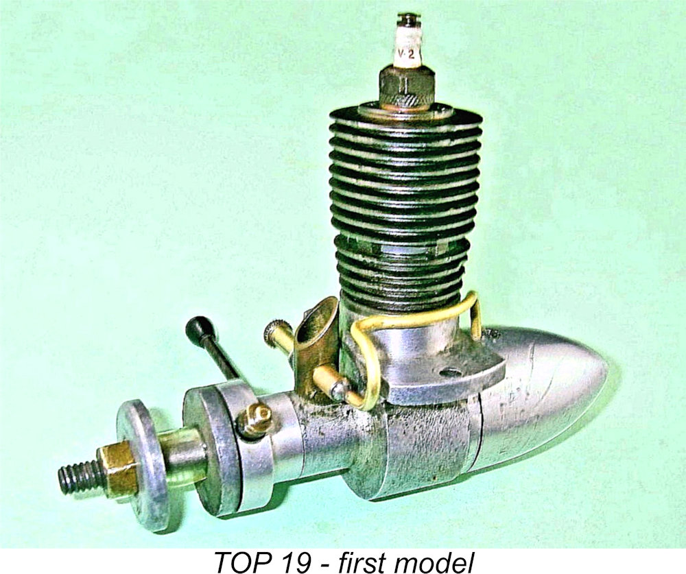
What is certain is that there were at least two quite distinct variants of the piston-valve TOP 19. I have no way of knowing whether or not these were contemporary with the TOP 23 described earlier. However, a number of features combine to allow us to place the two presently-confirmed 19 models in their correct order with considerable confidence. The model which seems to be the earliest version of the TOP 19 in my present possession is a piston valve design which is generally similar in layout to the 23 but dispenses with the aluminium sleeve below the exhaust port belt. Instead, the cylinder is extended downwards, with four extra fins below the exhaust ports. The cylinder has also acquired an extra cooling fin above the exhaust ports for a total of nine. This variant also has only two mounting holes, one in each lug, as opposed to the four holes seen on the 23 version described earlier. In addition, the outer ends of the lugs are curved in plan view rather than having straight parallel edges.
The crankshaft features the same composite construction seen in the TOP 23 model, the crankweb being staked onto the main journal in an identical manner. The shaft in this variant has what appears to be a rather marginal main journal diameter of 6.5 mm with a 4.5 mm internal gas passage. This leaves a wall thickness of only 1 mm to resist shear and torsional forces. One suspects that this may have been a weak point with this model. That said, the use of spark ignition at low compression ratios is relatively kind to the shaft in terms of operating stresses. The somewhat complex gland nut system for fuel line attachment seen on the TOP 23 has been discarded along with the externally-threaded needle and its tensioning hardware. Fuel supply is handled by a conventional spraybar-type needle valve assembly which uses a split thimble for tension. A fine M3x0.35 metric thread is used, which should give very precise mixture control. These changes could have been made for cost reasons. The fuel line continues to be a length of 2 mm diameter brass tubing, but this is now soldered directly to the spraybar. These changes may imply a slightly later date for the 19 model. Otherwise, the revised design is more or less identical to its .23 cuin. companion, retaining the same piston valve construction, the composite crankshaft, the bronze-bushed cast alloy con-rod and even the unusual timer design. The timers on my examples of the 19 and 23 are essentially identical. The TOP 19 - Second Variant
The most significant change in this variant was the abandonment of long-stroke internal geometry in favor of a square bore/stroke combination. Nominal bore and stroke of this variant are 15.9 mm each for a slightly reduced displacement of 3.16 cc (0.193 cuin. - still a 19). It's a bit of a puzzle why they didn't go all the way to the full Class A displacement by utilizing bore and stroke dimensions of 16.0 mm apiece. However, the difference is admittedly very small. All-up weight of this variant (with plug and tank) has crept up a little to 161 gm (5.68 ounces)
The revised top fin is provided with a ring of eight holes (as opposed to the former four) for the application of a pin spanner to tighten the cylinder. These holes are of larger size and are evenly spaced around a larger pitch circle diameter than formerly used.
Less obvious but still externally visible is the fact that the mounting lugs are considerably thinner than those of the earlier model. They do however retain the same two-hole mounting set-up with a single hole in each lug. Another subtle but still externally-visible feature of the revised crankcase is the fact that the lower part of the case beneath the mounting lugs has clearly been "cleaned up" by pushing the original sand-casting through a semi-circular broach which was open at one side to clear the upper casting. Apart from making the lower crankcase Internally, a number of significant changes are apparent. Apart from the revised bore/stroke configuration, the somewhat flimsy con-rod is now machined from a length of bronze, possibly a casting. Secondly, the shaft is now a one-piece component having the web and crankpin machined integrally with the main journal - the former composite construction has been superseded. The crankweb now features a machined-on counterbalance in addition to the cutaways on either side of the The diameter of the main crankshaft journal in this variant has been slightly increased to 6.7 mm, with the central gas passage retaining a diameter of 4.5 mm. As a result, both the wall thickness and outside diameter are marginally greater than in the earlier shaft. This change was presumably a response to some demonstrated level of weakness in the original shaft. A far more subtle change became apparent while I was inspecting the engine prior to reassembly. I found that the shelf inside the case was set lower than the bottom of the piston skirt at bottom dead centre. As a result, the piston valve was not mechanically constrained to open at any point in the cycle. It might be supposed from this that the designers were relying solely upon crankcase gas pressure to "float" the working piston and thus allow the valve to open. This might work at lower speeds, but at anything approaching normal operating speeds for such an engine the rather heavy working piston would take some stopping and valve efficiency would become greatly impaired if it worked at all.
This change underscores the possibility that the TOP 19 and 23 models were in fact produced concurrently despite their design differences. It would appear logical to assume that the addition of the fibre washer would have taken place simultaneously in both models. For this to have happened, the earlier versions without the fibre washers would have had to be already in existence concurrently. Although its shaft features a cam profile forward of the main journal, exactly like the two previous models, my example of this third variant arrived without a timer. I originally planned to make an exact copy of the timers on my two earlier examples. However, I found that I made a functional repro timer along the same lines as that on the earlier models, merely adjusting the dimensions to suit. It's highly unlikely that my home-made timer is exactly correct, but at least it looks appropriate and restores the engine to operable condition as a spark ignition unit. There may have been more variants of the TOP 19 piston-valve engine, but if so I have yet to encounter evidence for their existence. As far as is known, none of these models ever appeared as factory products in glow-plug form, so their production had presumably ceased as of late 1947. By that time in any case they would have been very much out of date in both design and performance terms. The TOP "A"
The major change that had come about as of early 1948 was the introduction of glow-plug ignition in the USA following its development into commercial form by Ray Arden. Japanese model engine designers would very quickly have become aware of this development as a result of contact with modellers among the numerous American members of the Occupation Force. Despite such awareness, it appears that Japan was relatively slow to make the wholesale conversion to glow-plug ignition. This was probably due to a shortage of supply both of the essential plugs and of the platinum-iridium wire needed to make them. However, by the latter part of 1948 a number of Japanese manufacturers had introduced glow-plug versions of their established spark ignition models, and a few had even developed purpose-built glow-plug models of their own. The makers of the TOP range were among the latter group. It was probably during the latter part of 1948 that they introduced a completely revised version of the long-established TOP 19. This was designed from the outset as a glow-plug model and was designated the TOP "A" to distinguish it from its spark-ignition predecessor. I don't know whether or not a companion .23 cuin. TOP "B" glow-plug model was introduced at the same time, but it is certainly possible. All that can be said in this regard is that I have yet to encounter any hard evidence for the existence of such a model.
The TOP "A" carried over a number of design features from the spark ignition TOP 19, including the screw-in blind-bored radially-ported cast iron cylinder with integral fins as well as the use of FRV induction. However, the piston valve was gone, being replaced by a conventional transfer system. In addition, the former cast tank was replaced by a far less substantial spun aluminium component secured by a central 2 mm steel stud and nut. There was no provision for a timer, and the fuel line was now a piece of flexible tubing in place of the brass tubing used previously. Finally, the brass venturi insert had been replaced by an integrally-cast component. The mounting lugs reverted to the straight outer edges of the original TOP 23 sparker, although they retained the single mounting hole in each lug as seen in the previous TOP 19 models. The lugs were also relocated lower on the case to place the mounting surfaces precisely on the thrust line. The TOP "A" was designed to take advantage of the full displacement allowance under Class A rules, featuring bore and stroke measurements of 16 mm apiece for a displacement of 3.217 cc (0.196 cu. in.). Complete Exhaust port arrangements were essentially unchanged from the earlier models, but the transfer porting was of course completely different. There were 4 milled transfer ports of unusual depth due to the fact that they were carried well below the level of the piston crown at bottom dead centre and actually extended below the male cylinder installation threads. These threads were of course interrupted at the transfer port locations. The actual bypass passage was formed by the space between the unthreaded lower cylinder and the crankcase interior wall. Overall, The revised thin-walled one-piece piston was made of steel - a perfectly reasonable material for use in a cast iron cylinder. Interestingly enough, it was initially formed by deep-drawing prior to lapping to fit in the bore. Even more interestingly, the gudgeon pin bosses were also punched out rather than drilled. This left the steel gudgeon pin supported by extremely thin bosses, and the pin was prevented from moving by being swaged into the bosses during assembly. This would make the replacement of the con rod somewhat problematic. The con-rod reverted to the original TOP 19 pattern of a cast alloy item with a bronze-bushed big end bearing. The shaft had a main journal diameter of 7 mm with a 4 mm diameter internal gas passage. The 0.3 mm increase in outside diameter combined with a 0.5 mm smaller internal gas passage diameter represented a significant increase in the strength of this component by comparison with the second variant of the TOP 19 sparker. This was probably a wise move in view of the greater stresses imposed by glow-plug operation.
This assembly bears no resemblance whatsoever to any crankshaft that I’ve encountered in an original TOP engine. In fact, it bears all the hallmarks of a rather inexpert repair following a shaft failure. It seems likely that the original shaft was a one-piece item which was very similar to that seen in the second variant of the TOP 19 - the designer is most unlikely to have reverted to a composite shaft for the more structurally-demanding glow-plug application. Most likely, the original shaft failed during initial test running - the engine had clearly seen a bit of bench testing, although there are no mounting marks on the bearers. The owner proceeded to cobble up the component described above, using the original main journal as his starting point. This must have been done Fortunately, I could do a bit better. I made a new one-piece shaft of good quality steel, using the "mock-up" as my pattern. This went into the engine very nicely indeed, thus rendering it fully serviceable (as a subsequent test proved beyond doubt). I did make one change when doing this work - I made the induction port a little narrower and more elongated. The 5.5 mm diameter hole in the original journal was in my opinion a little too large for comfort and removed more material from the shaft than I felt to be desirable. It would certainly have created a serious stress concentration at that always-vulnerable point. It also gave induction timing which in my view was a little too extreme for an engine of this specification. The revised shape gives a slightly reduced induction period, but this is amply compensated for by the more rapid opening and closing of the induction system. The shaft should also be appreciably stronger than it was before. The shaft runs in a bronze bushing inside the integrally-cast main bearing housing. This housing also incorporates the integrally-cast intake venturi which replaces the former pressed-in brass component. The bore of the venturi is 5.5 mm, with a 3 mm spraybar being fitted. In keeping with the two previous TOP 19 models, a conventional needle is used, tension being provided by a split thimble in the usual manner. The big end bearing on the con-rod has a very well-placed oil hole which communicates directly with the upper (loaded) surface of the bearing rather than at the bottom or side as in the more usual case. Overall, this appears to be a well thought-out and competently-executed design, which makes it appear almost certain that the cobbled-up crankshaft described earlier was not the work of the clearly very capable TOP manufacturers.
I guessed the needle setting at 3 turns open, which proved to be very close to the right setting. The engine started on the very first flick following a prime (no kidding!) and ran very smoothly indeed. Needle response was very positive without being the least bit critical, making the establishment of settings very straightforward. After a 20 minute break-in period on a slightly rich needle to bed in the new shaft bearings, I tried the engine fully leaned out for a few short runs. It didn't produce a lot of power for its displacement - it could only manage 9,500 rpm on this prop, indicating an output of around 0.16 BHP at this speed. Obviously, it might do slightly better than this at higher speeds, but in any case this isn't totally dismal for an engine of this vintage. Moreover, running qualities were first-rate - very smooth indeed with no tendency to sag. Starting qualities remained outstanding throughout - one or two flicks every time, hot or cold. The TOP "A" would have made a very acceptable powerplant for beginner training and sport flying. Despite its worthy qualities, it must be apparent that this engine followed its predecessors in looking far more to the past than to the future. The TOP designer clearly still had some way to go to get completely into step with emerging trends in model engine design. As we shall see, he was well up to this challenge, a fact which he demonstrated very clearly with the next model to be described - the TOP 33 glow-plug model. The TOP 33 The extreme scarcity of surviving examples makes it apparent that production figures for the TOP "A" just described were relatively low. No doubt the engine's rather retrograde design layout had much to do with this. It is of course equally possible that the makers were already in the process of diversifying their production, with model engines becoming more of a sideline as time went by.
The TOP 33 was a thoroughly up-to-date design by 1950 standards. It was based upon a sturdy sand-cast case which incorporated an integrally-finned cylinder jacket, a large cast-in bypass passage, an exhaust stack and an integrally-cast main bearing and venturi. It featured a sturdy plain bearing crankshaft with FRV induction, a generously-ported loop-scavenged cylinder and a separate head with the plug displaced towards the transfer side. The latter was a commonly-adopted feature at the time. Its purpose was to speed up the full involvement in the combustion process of the semi-isolated pocket of mixture separated from the rest by the piston baffle. Bore and stroke of the TOP 33 were a checked 19.0 mm and 18.3 mm respectively for a displacement of 5.189 cc (0.317 cu. in.). The engine weighed in at a fairly hefty 224 gm (7.90 ounces) complete with tank, fuel tubing and plug. The sole identification was the "TOP 33" designation cast in prominent relief onto the bypass passage.
The illustrated example has very large rectangular exhaust and transfer ports with the exhaust port being centrally bridged, presumably to preclude tipping of the piston and snagging of the upper lip of the port. Photos of another example show that some of the engines had slightly narrower un-bridged exhaust ports.
The crankshaft is a solid one-piece steel item - the former composite construction has been dropped. The shaft is very sturdy indeed, with a heavily counterbalanced full-disc crankweb. Main journal diameter is a nominal 11.5 mm with an 8 mm diameter central gas passage. As in previous models, a simple round hole forms the induction port in the crankshaft journal. The integrally-cast venturi has an internal diameter of 7.5 mm and is fitted with a spraybar having a diameter of 4 mm. The spraybar is internally threaded to accept an externally-threaded needle of typical Finally, the backplate is a screw-in item which is machined from a sand-casting. As on the TOP "A", the tank is secured using a 2mm steel stud and nut. This engine incorporates all the latest design features for stunt engines as of 1950. It is also very well made, especially where it counts - all key fits are excellent, although this used example has some wear in the con-rod small-end bearing. Despite this, the engine starts and runs very well indeed on the bench. However, the sterling qualities of the engine were clearly insufficient to encourage the TOP manufacturers to retain a foothold in the very competitive model engine industry which was then developing in Japan - the competition from the likes of O.S., Enya, Mamiya and Fuji was too much, and perhaps greener pastures beckoned. It seems fairly certain that the TOP 33 was the final model in the TOP range and that its manufacture ended in the very early 1950's. The number of examples produced was clearly very small. Conclusion Unless additional information comes to light, there's little more that can be said about the TOP range. The TOP 19 spark ignition unit appears to be the most frequently-encountered model today, although it is far from common. However, examples in varying states of completeness still seem to turn up from time to time. The TOP 23 is seen rather less often, and the two glow-plug models described above are elusive in the extreme. The TOP 60 may almost be viewed as having mythical status - we know that it existed, but very few people will ever see one in the metal! The relative rarity of the TOP engines today despite their production life of perhaps 6 years appears to confirm that the company that made these engines was never a major producer. Indeed, the range may never have achieved much more than "regional" status, with the engines being sold for the most part to modellers located in the general vicinity of their native Osaka. They may well have begun as something of a small-scale "cottage industry" product similar to many others such as the Reeves, Healey, Milford and M.E.C. engines in Britain. Their withdrawal from production after the development of the excellent TOP 33 may not actually reflect a market rejection of that model - rather, it may simply reflect a move away from small-scale model engine production into more remunerative business activities at a time when such opportunities were opening up again in Japan following the disruption caused by the aftermath of WW2. Still, an interesting range and a good indication of the capabilities of the Japanese model engine industry well before the English-speaking modelling world even became aware that there was such an industry. All in all, a TOP-class effort! ________________________________ Article © Adrian C. Duncan, Coquitlam, British Columbia, Canada First published on MEN August 2011 This revised edition published here August 2023
|
 Here I’ll peer deep into the mists of time to share what can be learned about another ultra-obscure range of early model engines from Japan. I'll be looking at the TOP engines, which may possibly have had their origins prior to WW2 and were certainly among the earliest post-war Japanese ranges.
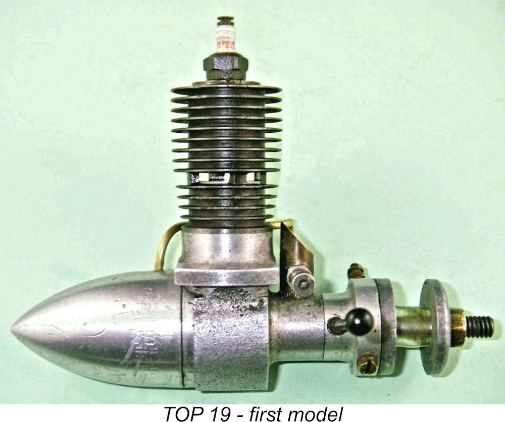 To accomplish this goal, I'll have to rely on an examination of the engines themselves plus a few scraps of information gleaned from the Web, from contacts in Japan and from such sources as box labels. I accept that this yields what must be a very incomplete picture, but I feel that presenting something that at least acknowledges the existence and scope of the range is far better than doing nothing at all! If any reader has authoritative information to add, I’d be extremely happy to hear from you. The recording of model engine history is a collective effort, to which all contributions will be openly and gratefully acknowledged.
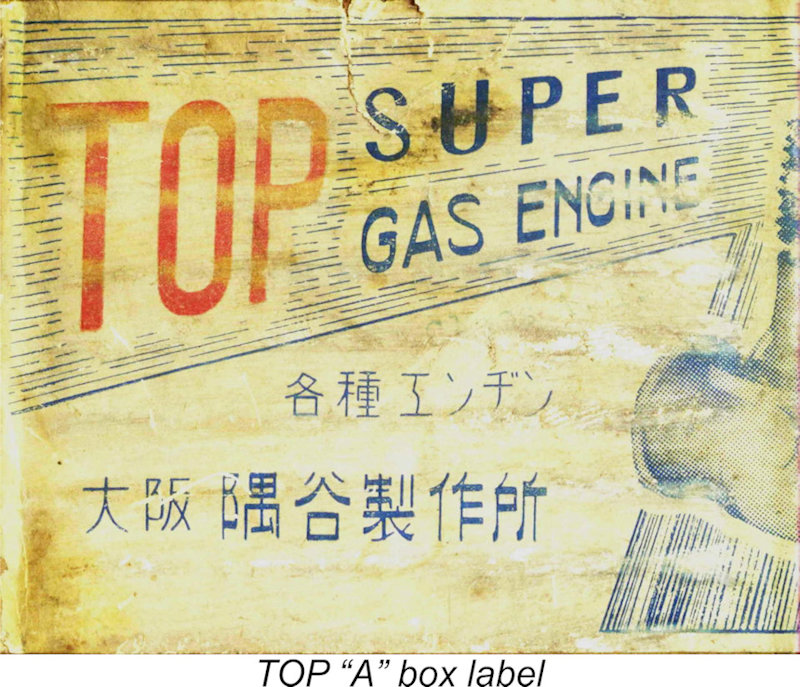 By contrast, pioneering Oriental makers frequently drew their names from the world of the abstract, with names like Hope or Great Leap Forward to inspire the would-be buyer. It is therefore not surprising that the notion of a product being "best" or "first class" should be highlighted through the naming of such products. The name "TOP" falls squarely into this category.
 Further evidence of the engines' origins comes from the four Japanese characters in the stamped-on cartouche seen in Katakana script on the left-hand engine mounting lug on many examples. This series of characters translates with no ambiguity whatsoever into "Sumitani". A check of the word "Sumitani" on Google Japan reveals it to be a not uncommon Japanese family name which is certainly in harmony with the name of the Sumiya Works at which the engines were apparently made.
 Although at present I have absolutely no proof, there are a number of factors which suggest that the TOP engines may have been originally designed by (or their design significantly influenced by) a certain Mr. N. Haruyama. This individual unquestionably produced his own post-war range of model engines under the Haru brand, which for a time at least were contemporary with the TOP range. Moreover, the TOP and early Haru engines shared many design attributes. It must be repeated that there is absolutely no direct evidence which confirms the TOP/Haruyama connection, but it is a possibility that merits recognition.
 One such fact is the appearance on all presently-known TOP piston-valve engines (their earliest products to my current knowledge) of the word TOP in Latin characters inside a lozenge-shaped cartouche on the right-hand mounting lug. Prior to the end of WW2, Japanese manufacturers were strictly forbidden by the ultra-nationalist Japanese government of the day to identify their products with anything other than Japanese characters. Certainly, no other presently-known pre-war Japanese engines display Latin characters. Hence the appearance of the word "TOP" in Latin script must cast serious doubt on the cited 1940-41 dating of the TOP engines - the fact that many TOP engines also carry a second cartouche in Japanese characters does not affect this conclusion.
 It has generally been held that the most prolific TOP product at the outset was a .196 cuin crankshaft front rotary valve (FRV) spark ignition model, of which I’ll have more to say in a subsequent section of this article. This was accompanied by a .23 cuin. model of essentially identical design, which has always been presented as being far less common. The fact that Alan Strutt and I had no fewer than three examples of the TOP 23 between us as of my initial time of writing in 2011 must cast some doubt upon the traditional view of the relative rarity of the TOP 19 and 23 models. It actually appears possible that they were produced in quite comparable numbers.
 Returning to the original TOP models, an interesting feature of those engines was their use of a piston valve for transfer purposes. In this system, the conrod and gudgeon (wrist) pin are carried in a shuttle piston of smaller diameter than the main bore. This shuttle piston is accurately fitted to a smooth secondary bore formed within the main working piston, being free to slide up and down within the working piston while being retained in the working piston for assembly purposes using an internal circlip around the base.
  Consequently, when the compression phase begins after the exhaust ports close, the hole is sealed and the composite piston is able to resist the increased pressures experienced during both the compression and power strokes. The pressure on the top of the working piston naturally increases the closure pressure on the piston valve - the higher the pressure, the tighter the seal.
 were no insurmountable impediments to an exchange of information between the USA and Japan prior to that date since both were non-combatants and both communication and travel between the two nations remained open. Indeed, we know that the
 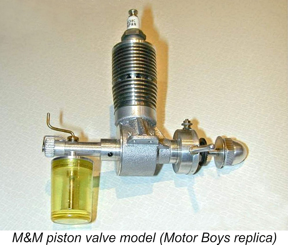 The far rarer
 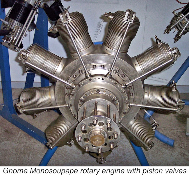 It's also possible that the piston valve concept reached Japan far earlier as a result of the often-overlooked circumstance that Japan was an active ally of both Britain and America during WW1, mainly in a naval capacity. A number of prominent early WW1 aircraft were powered by 4-stroke
 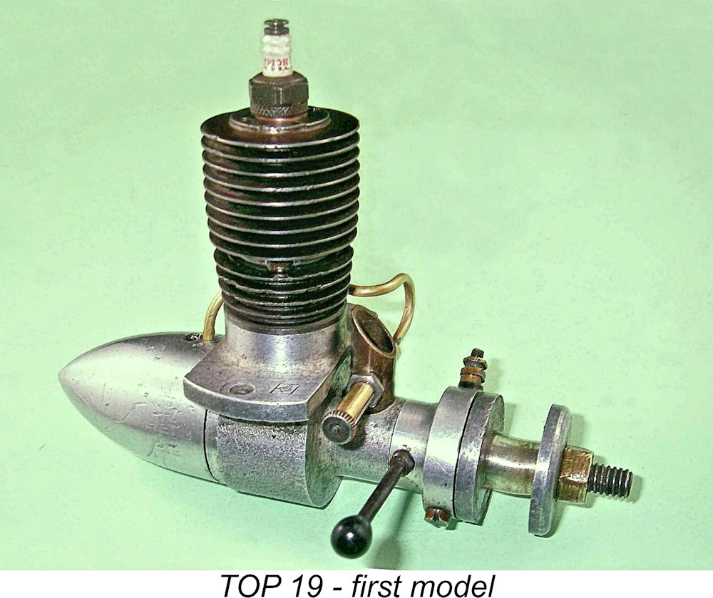 Regardless of their inspiration and whether or not any engines were produced prior to WW2, there's no doubt that manufacture of the post-war TOP engines must have got underway very soon after the conclusion of the conflict. The .19 and .23 cuin. piston valve models seem to have been among the company's earliest products. TOP was only one among a number of now-obscure Japanese ranges whose manufacturers evidently attempted to tap into the market opportunity for model goods created by the presence of the mostly American personnel serving in large numbers in the Occupation Forces. A significant number of these individuals were modellers in their spare time.
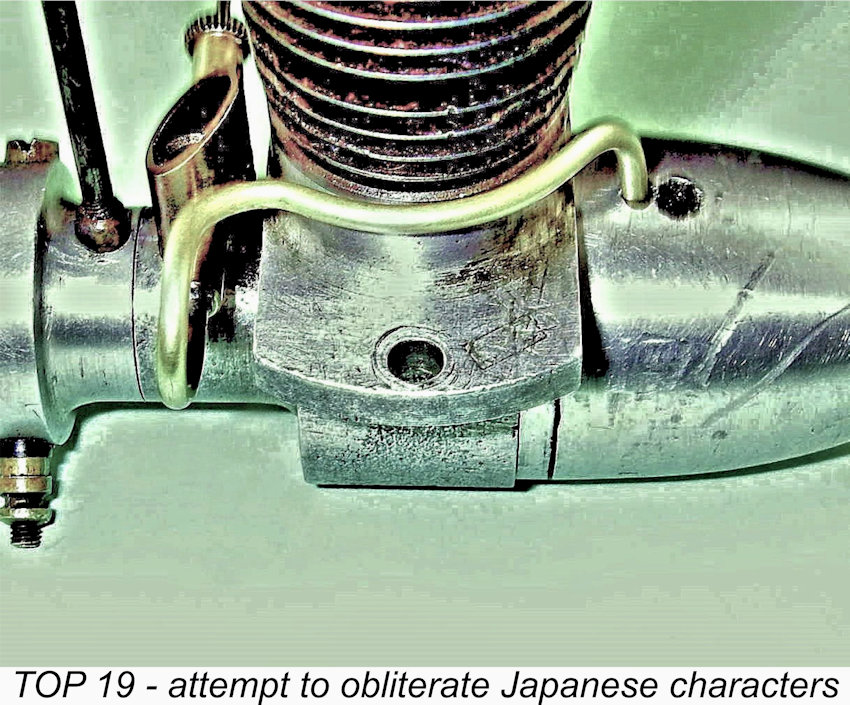 It may be of further significance in this context to note that the illustrated first model example of the TOP 19 has seen a determined and largely successful effort to eliminate the Japanese ciphers in the cartouche on the left-hand mounting lug by scraping - the TOP designation in the cartouche on the right-hand lug has been left untouched. This is definitely not use-related, but unquestionably represents a deliberate action on the part of a previous owner. It seems possible that this engine ended up in the hands of an overseas owner who still harbored resentment against the Japanese and wished to obscure any visible evidence of the engine's Japanese origins. Or perhaps a Japanese seller did the same to render the engine more attractive to an overseas buyer.
 It was at some point in the early post-war period that the aforementioned Mr. N. Haruyama introduced a range of very similar piston valve engines under his own Haru designation. The architectural and design similarities between the Haru engines and their TOP predecessors are sufficiently striking to reinforce the previously-mentioned possibility that Mr. Haruyama may have been involved with the TOP range before going out on his own. Among many other similarities, his engines were identically marked with a pair of lozenge-shaped cartouches, one with Japanese ciphers and the other with the name "Haru" inside it in place of the "TOP" designation. I must re-emphasize that I presently have no proof of this connection, but it seems worth raising as a possible subject for research by others.
 for the TOP “A” - if one looks at the attached image very carefully, one can just make out traces of the Japanese characters on the original label which have been covered up by a stick-on addendum hand-written in Latin script. It appears that this addendum was added to render the content of the box more attractive to an English-speaking buyer. A new-in-box TOP 23 turned up some years back in Australia in an identical box without the add-on addendum.
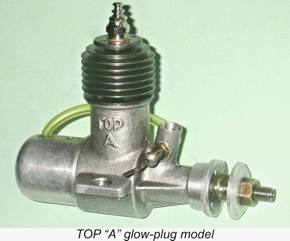 In late 1947, one of the greatest innovations ever to influence model engine design made its appearance in commercial form - the miniature glow-plug had arrived! The makers of the TOP engines were not slow to recognize the implications of this, and they seem to have been relatively early into the field with a .196 cuin. glow-plug offering of their own, designated the TOP “A” to distinguish it clearly from its spark ignition TOP 19 predecessors. It is unclear whether or not this model had a .23 cuin. companion in keeping with its .19 cuin. spark ignition ancestor or whether there was a TOP “B” glow-plug model, but neither possibility can be discounted - I simply have no evidence at present.
 No charge of retrospective design could be leveled against the next model in the range, which appears to have been the final model engine offered by TOP. This was a well-made and thoroughly up-to-date .32 cuin. glow-plug design which was designated the TOP 33 for reasons which must remain obscure - perhaps a carry-over from the name of the earlier TOP 33 spark-ignition model mentioned above.
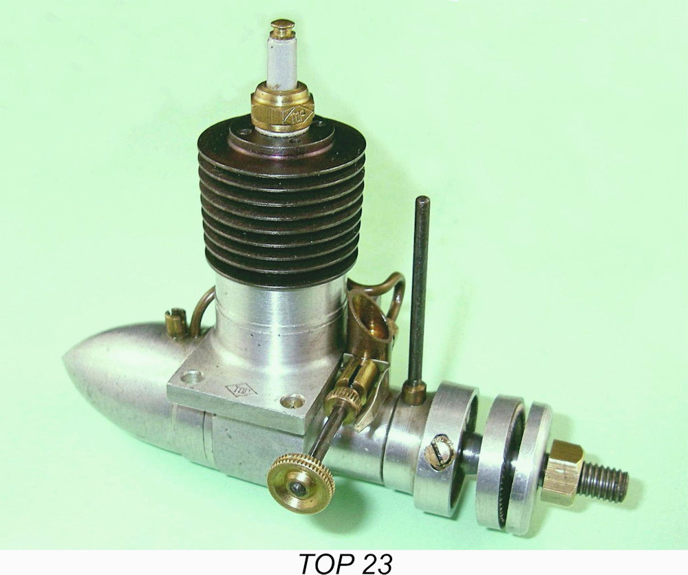 As far as I’m aware, this spark ignition piston-valve model was among the first products released by TOP. Although oral information from Japanese sources indicates that the TOP range had made its appearance by 1941, this statement is open to question for the reasons stated earlier. It seems highly likely that all presently-known examples date from 1945 or later.
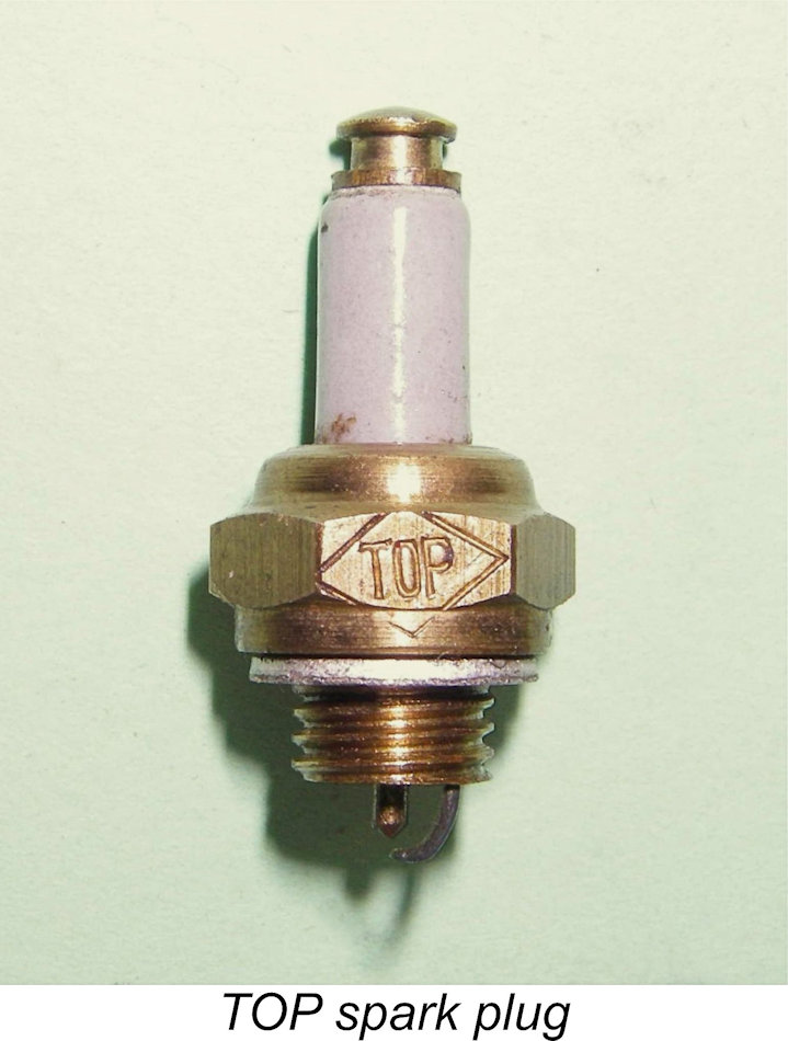 nominal 15.4 mm and 17.4 mm respectively, the resultant displacement being 3.66 cc (0.223 cu. in.). The checked weight with plug and tank is 176 gm (6.21 ounces). The spark plug fitted to the LN example is also identified as a TOP product, demonstrating that the makers did not confine their activities to engine manufacture.
 working piston it effectively seals off the central 7.2 mm hole. A ring of small holes communicating with the interior of the shuttle piston surrounds this boss to provide gas passage when the valve is open. This valve seems to work very well since the illustrated examples have excellent compression when flipped over, albeit at a relatively low compression ratio.
 at the junction between the crankweb and journal and a steel dowel force-fitted to maintain the correct annular relationship between the two components. You can just make this out in the attached illustration. The crankpin is machined in unit with the crankweb, which has been counterbalanced through the removal of material on the crankpin side.
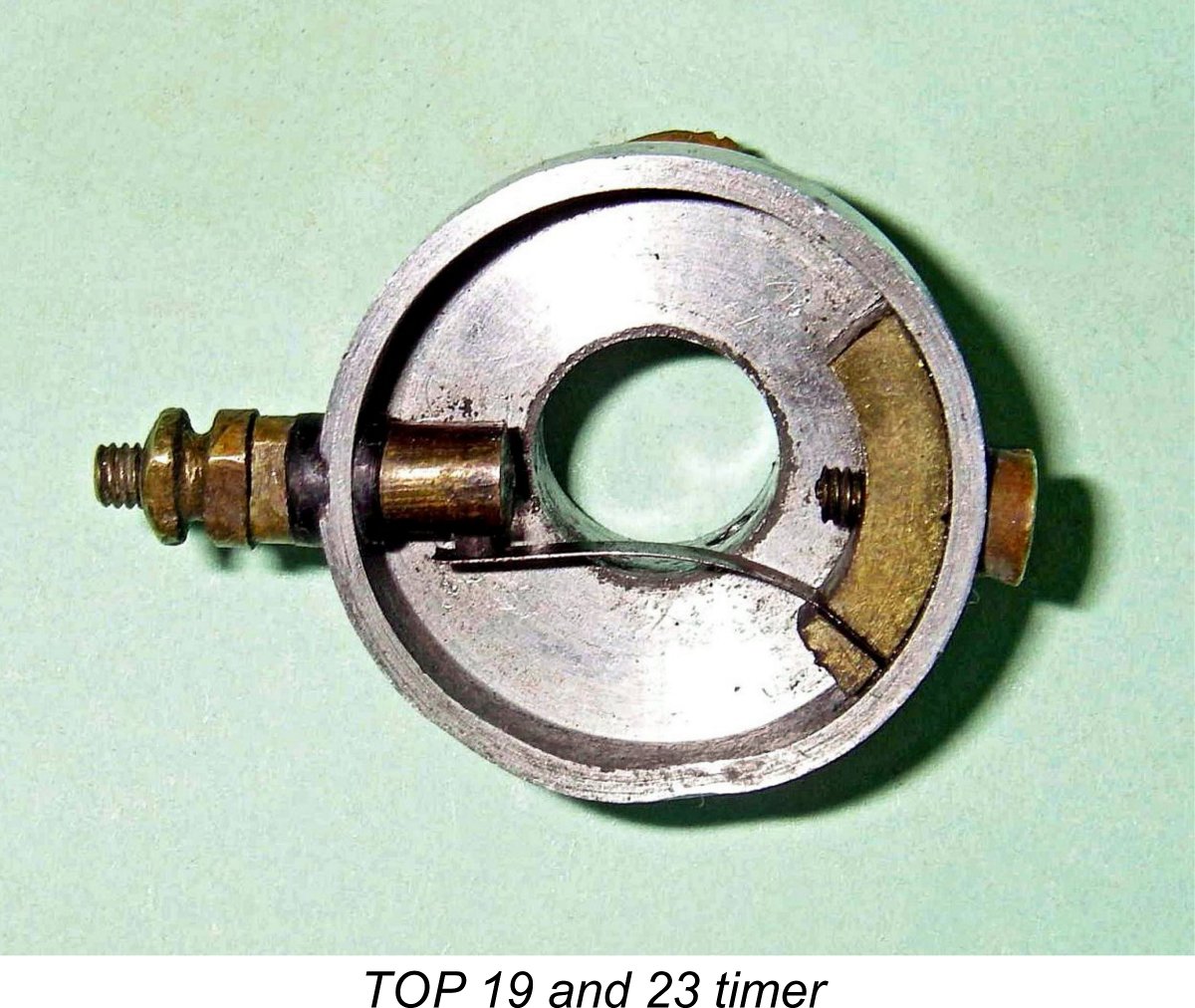

 Somewhat unusually, the typically Japanese brass venturi is axially grooved around the base to discourage twisting and is then pressed into a hole in the main bearing rather than being threaded in the more usual manner. The spraybar is internally threaded to accommodate an externally threaded needle with a brass control knob at the outer end. Tension is provided by a spring clip which engages with a serrated disc mounted on the needle.
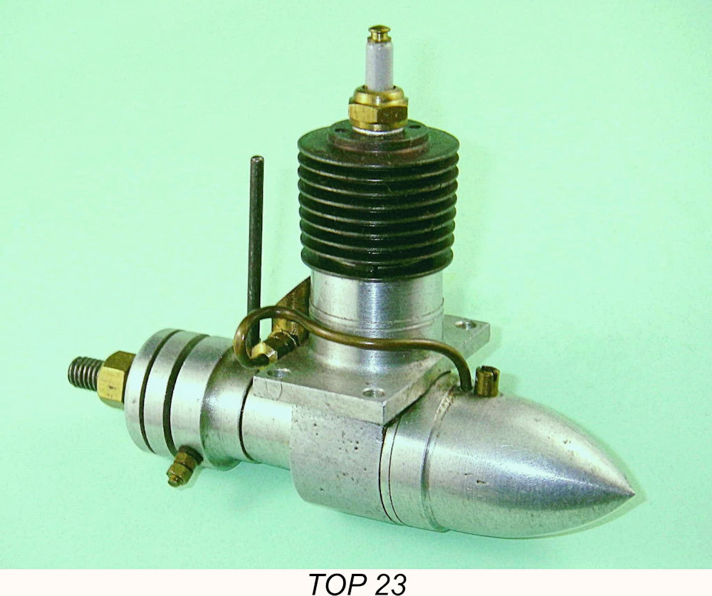
 At the present time I have yet to encounter an example of the TOP 19 which is built to the same external configuration as the 23 model just described. On page 193 of Mike Clanford's useful but often unreliable book "
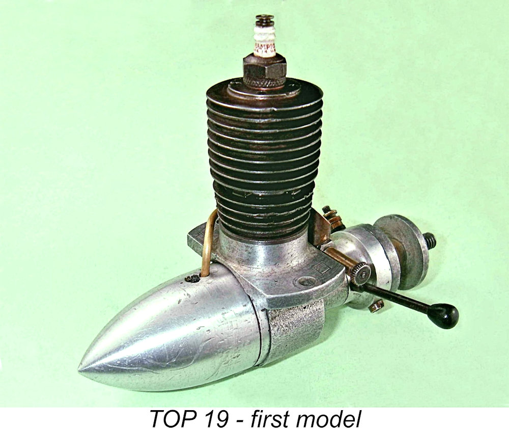 Like the 23 unit described earlier, this variant of the TOP 19 is a long-stroke design. However, it is far closer to square geometry than its 23 companion, actually having a slightly larger bore despite its smaller displacement. Measurements taken from two examples have confirmed that it has a nominal bore of 15.8 mm and a nominal stroke of 16.5 mm for a design displacement of 3.23 cc (0.197 cu. in.). All-up weight with plug and tank is 156 gm (5.5 ounces).
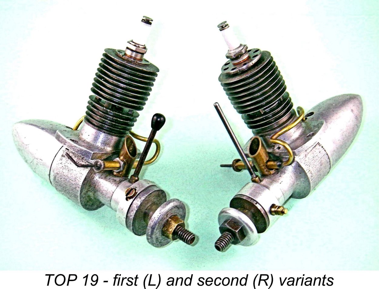 At some indeterminate point in time, a second variant of the TOP 19 piston-valve model was produced. At first glance this looks very similar to the first variant already described, but closer examination reveals many differences, some of them highly significant. I don’t presently know if there was a similarly updated .23 cuin model, but this possibility cannot be ruled out.
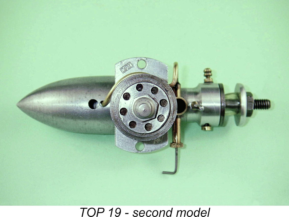 The most obvious externally-visible changes are to the cylinder and the tank. Taking the cylinder first, this item retains the blind bore, radial exhaust porting and integral fins of its predecessor. However, it has only three fins below the exhaust ports instead of the former four. It has the same number of fins above the ports (nine in total), but the topmost fin has been made far thicker and also has a smaller outside diameter. This mirrors a Japanese design trend at this time since it closely resembles the approach taken in the contemporary
  The tank is significantly longer, presumably indicating that the earlier tank had been found to give too short a run for some applications. The additional overall length of the engine resulting from this modification is partially taken up by the flange on the backplate between the male backplate and tank installation threads being made substantially thinner.
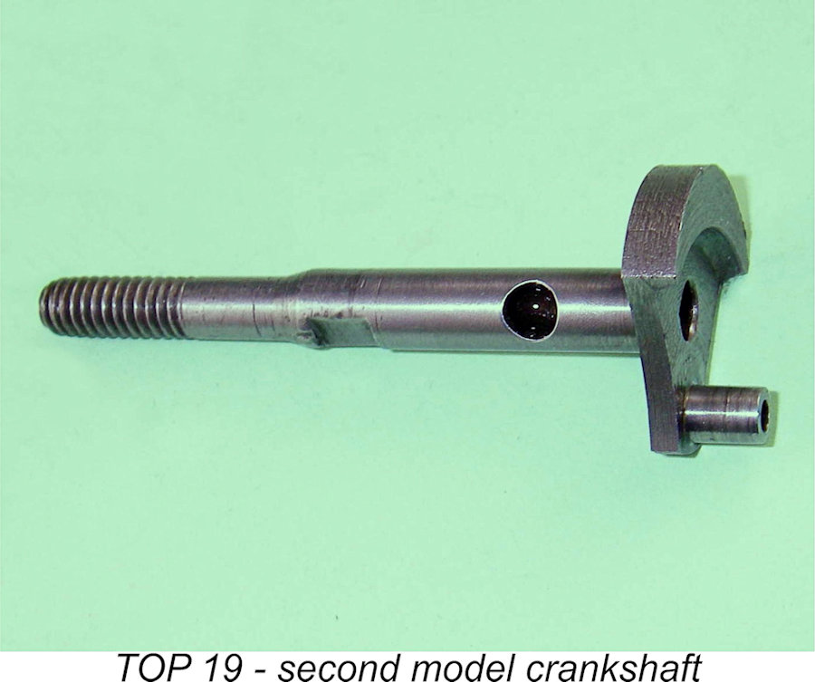 perfectly round and on the same axis as the backplate and shaft, it's hard to see what this step accomplished, but the evidence that this was done is unmistakable.
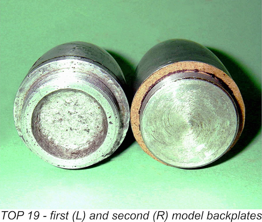 crankpin. Finally, the recess in the front face of the backplate has been eliminated - a good move in terms of reducing crankcase volume and hence improving pumping efficiency.
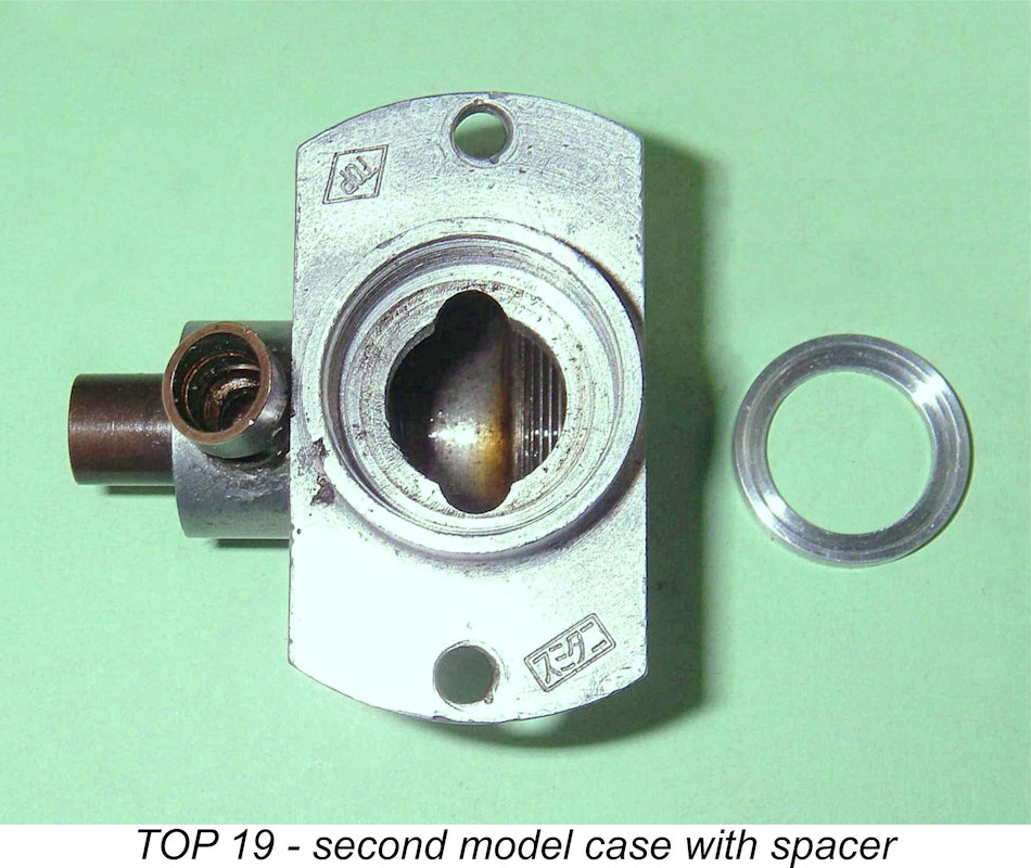 I found that there was a substantial gap between the shelf and the bottom of the screw-in cylinder when the cylinder was screwed fully home. This led me to the deduction that the engine originally had a fibre washer and circlip similar to the one seen in my pristine example of the TOP 23 illustrated earlier. Not having any suitable material at hand, I fitted an aluminium spacer of suitable thickness, and valve function was restored. I will make a fibre insert when I find some suitable material.
 despite the increased diameter of the crankshaft journal, the outside diameter of the bronze main bearing bushing was actually reduced. Hence the outside diameter of the exposed portion of the bushing upon which the timer is mounted is slightly smaller than that of the previous model and bearing wall thickness is considerably less. Moreover, the prop driver of the third variant also has a smaller diameter than that of the previous model and is set somewhat further forward from the end of the main bearing. Accordingly, the timer from the earlier variant did not come anywhere close to fitting.
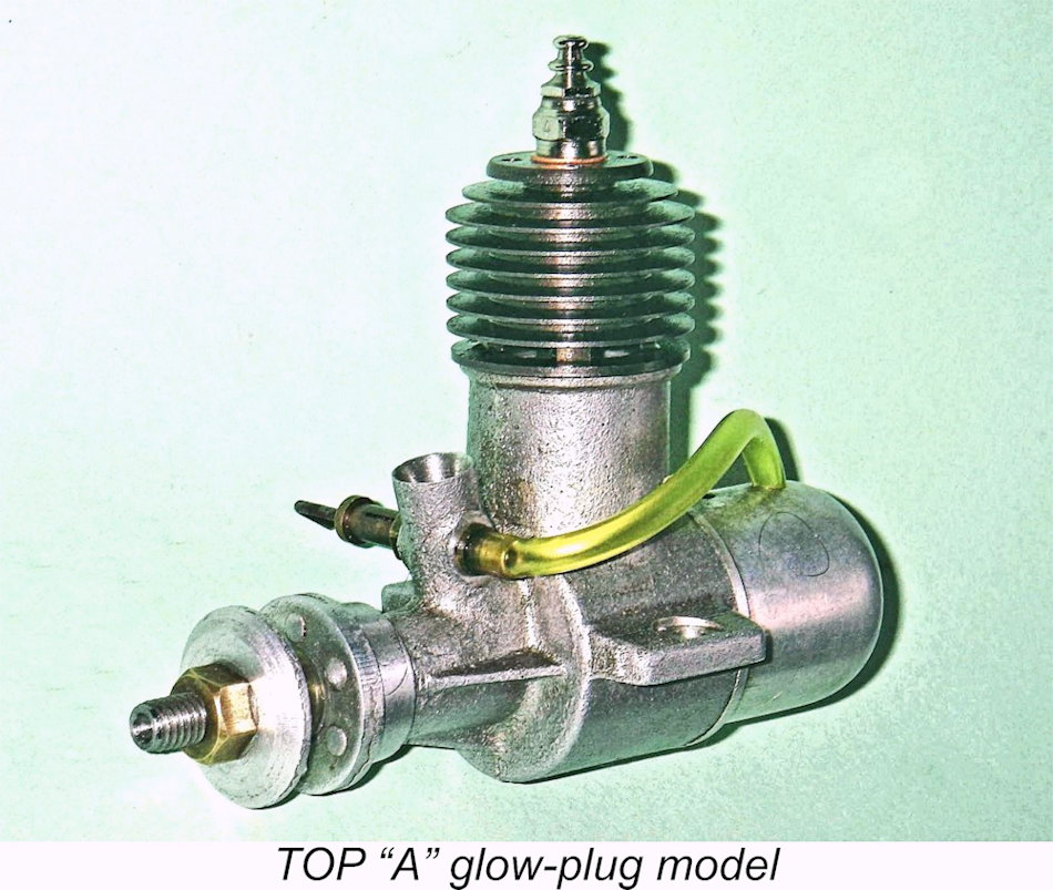 Despite becoming increasingly out of date as time went by, the piston-valve TOP models and the possible 29 and 33 models mentioned in the earlier overview must have sold well enough that the company was still in the model engine business as of 1948 and in a position to develop new offerings which reflected the rapidly-changing face of the model engine design picture. Indeed, the very fact that they did so indicates that they had managed to secure a sufficient foothold in the domestic marketplace as it then existed to justify their ongoing efforts.
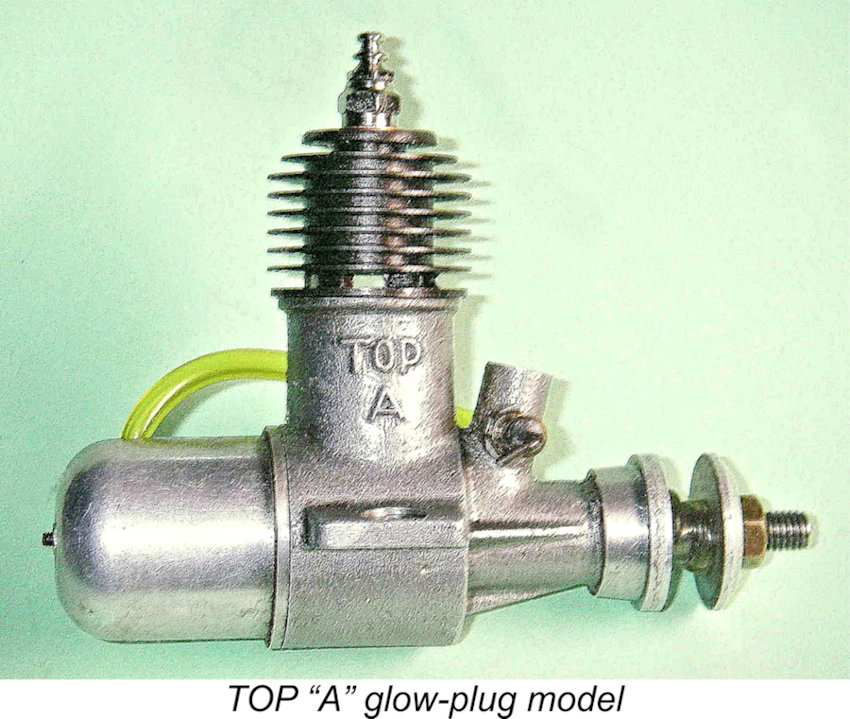 The fact that the TOP "A" was targeted at least in part towards overseas purchasers is demonstrated by the fact that the engine was identified on the previously-illustrated box label in English as a "TOP Super Gas Engine", although the rest of the writing was in Japanese characters. Moreover, there were no Japanese ciphers upon the engines themselves - the sole identification consisted of the "TOP A" designation cast in relief onto the right-hand side of the crankcase. The former cartouches were no longer in use. These may have been a "signature" of Mr. Haruyama, who had left to form his own company by this time if my speculations regarding his earlier involvement with the TOP range are correct.
 with tank, plug and fuel tubing, it weighed a commendably light 126 gm (4.44 ounces). Compression ratio was dramatically increased over that of the earlier sparkers, being of the order of 8 to 1 based on rough volumetric measurements. Together with the lower piston crown resulting from the abandonment of the piston valve, this accounts for the far more squat appearance of the engine.
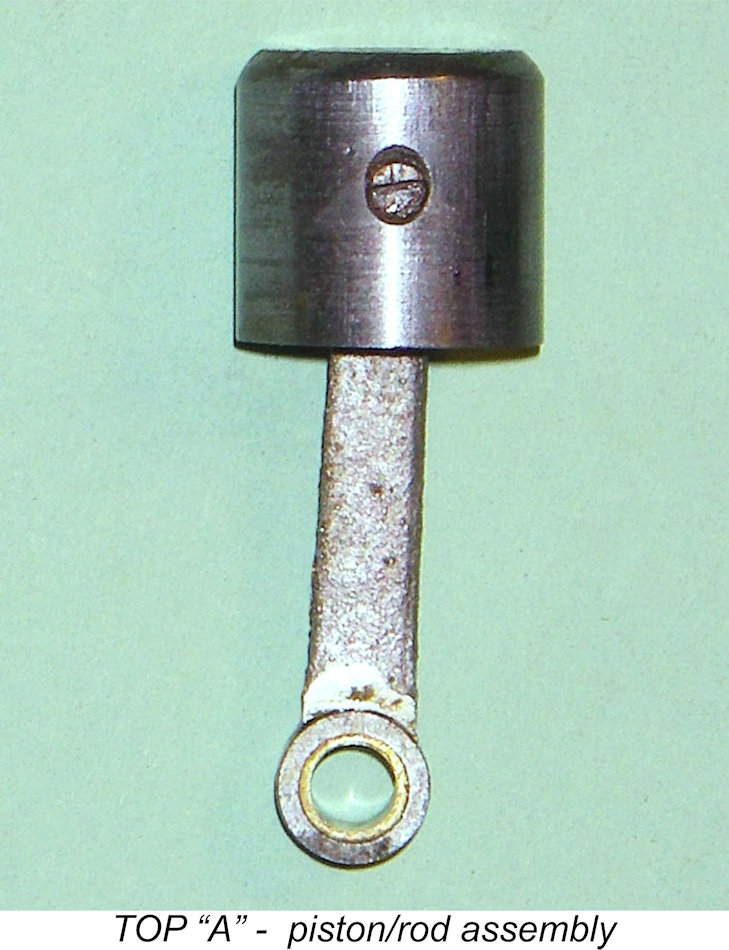 the transfer arrangements appear well designed for relatively free breathing as well as exceptionally effective piston cooling and lubrication.
 The illustrated example of this engine appears to be like new in the box, complete with its cast bench mounting and combination spanner. However, as received, it had a most odd crankshaft configuration. The crankweb was of brass with a pressed-in steel crankpin and was itself rather crudely soft-soldered to an equally crudely hand-filed or ground square section on the inner end of the main crankshaft journal. This assembly was very inexpertly carried out - the crankpin was well out of alignment with the main journal, and the fitting of the crankweb was very far from perfect.
 simply to make the engine appear complete and therefore saleable. Very sharp practice if so - the shaft as received would have lasted about 5 seconds in use and would have taken the rod with it!
 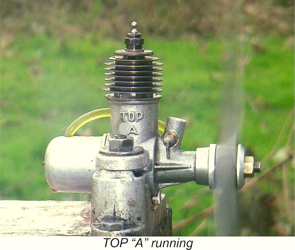 Having made a new shaft for this engine, I felt obliged to confirm that it was fully functional by giving the engine a few bench runs. In doing so, I was careful to protect the unmarked bearers. I used a 9x4 APC glass fibre prop for the test, with a 10% nitro fuel having a high castor oil content.
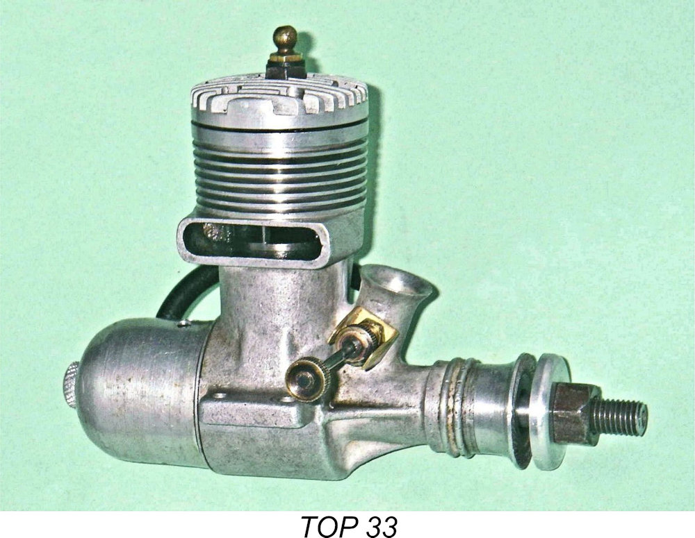 It would in fact have been easy for the manufacturers to give up on model engines altogether, and it's to their credit that they decided instead to have another go at the market with an all-new design which was right up to the minute in design terms. It's impossible to be certain, but on strictly architectural grounds we'd probably be fairly safe in dating the introduction of the next and, as it turned out, final model in the TOP range to 1950 or thereabouts. This was the TOP 33 glow-plug model, which had an actual displacement of .32 cuin. (5.189 cc) despite its name.
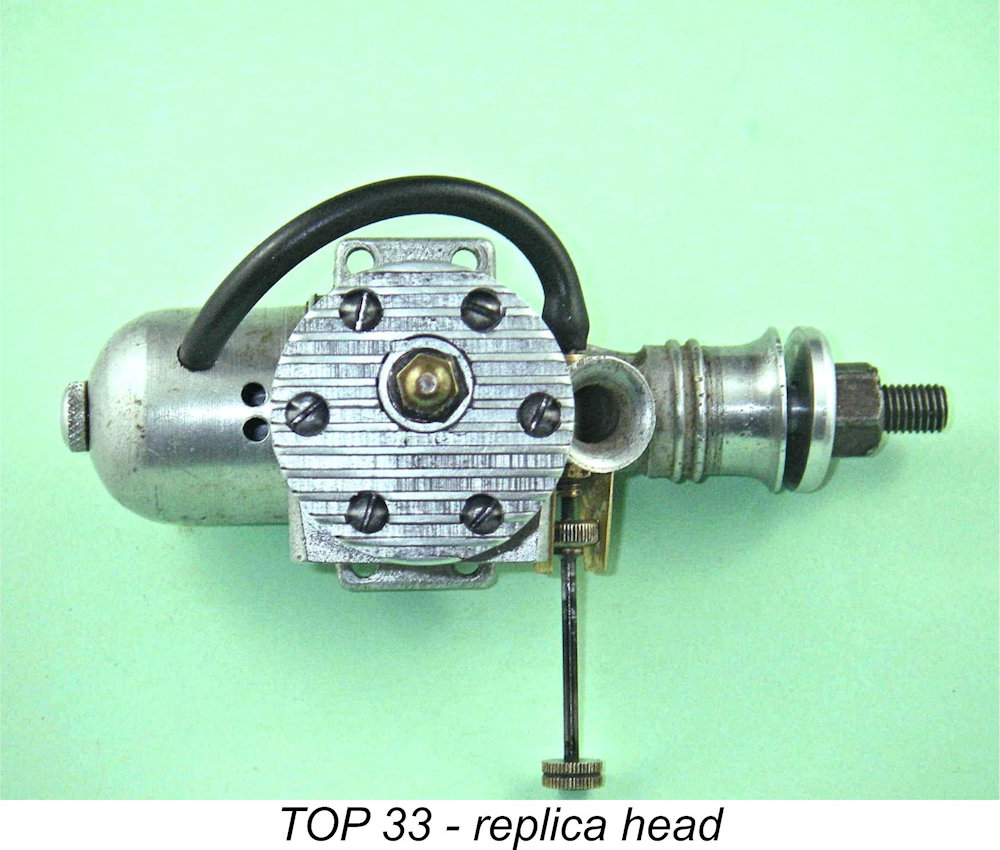 The illustrated example of the engine arrived without a cylinder head or tank. The head in the illustrations is of my own making, copied as best I could from photos of other examples. The fin configuration and plug location are correct, but there's no way of knowing what the original combustion chamber looked like. I simply made a conventional early 1950's combustion chamber and set the compression ratio at 7.5 to 1 - a good average figure for a stunt engine of this period running on low-nitro fuel. The head is attached with six 3mm slot-head screws having rounded heads, which I also had to make. The tank is a look-alike spun aluminium item from my spare parts stash which fits the engine as if it was made for it!
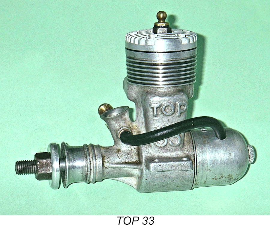
| |