
|
|
The “Japanese Bee” - the O.S. 1 cc Diesel
This is my second article on the subject of an extremely obscure and frequently overlooked product of this famous company. My first such piece focused upon the very rare sand-cast .29 cuin. O.S. twin-stack spark ignition unit which was the direct predecessor of the famous twin-stack .29 and .36 models produced by O.S. in the late 1940’s and early to mid 1950’s. That model was a very original design which performed at an unexpectedly high level, as my own tests have shown. The same claim to originality can’t legitimately be made about the subject of the present article, the O.S. 1 cc diesel! This is because it was a quite unashamed copy of the British E.D. Mk. I Series I Bee which had first appeared in mid 1948. The image below at the right should amply confirm this statement. Prior to 1957, the O.S. company had shown very little interest in diesels as far as the rest of the world In the absence of any definite information regarding whether or not this engine ever received an official company name, I’ve chosen to call it the O.S. “Bee”. If any reader can supply the correct Japanese name, I’d be most grateful! In the event, the O.S. “Bee” did not remain in production for very long - evidently, its "novelty" appeal in a Japanese context didn't translate into sufficient sales interest to justify continued production. Japanese modellers emulated their American counterparts by gravitating en masse from spark ignition to the glow-plug motor, inducing O.S. to resume doing what they did best - producing high-performance glow-plug models to very high manufacturing standards. Their short-lived 1 cc diesel actually made so little impression upon their corporate consciousness that like the previously-mentioned sand-cast 29 sparker it was omitted from their famous 40th anniversary summary sheet which incorrectly claimed to show all of the models that they had ever produced as of 1976!
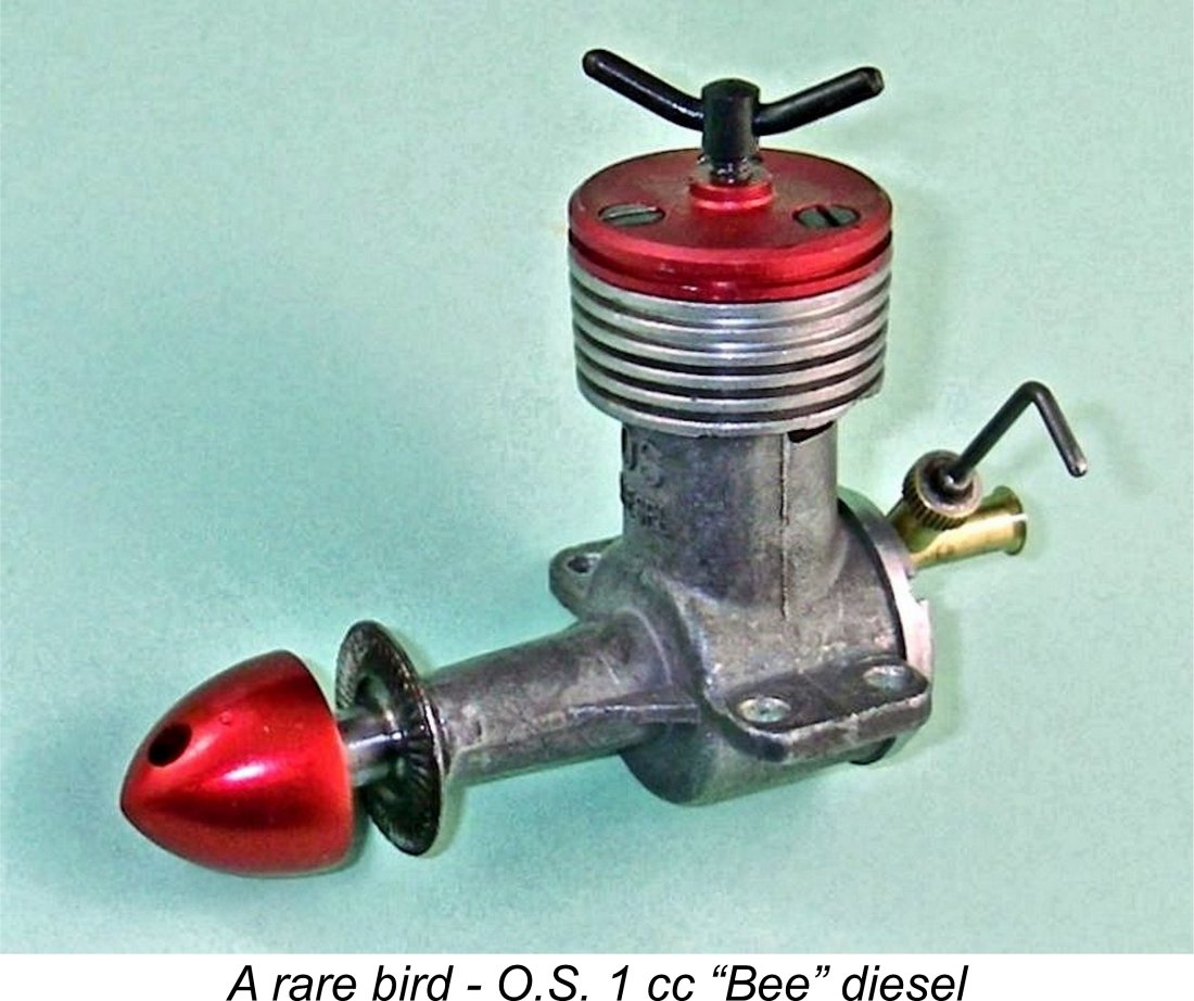
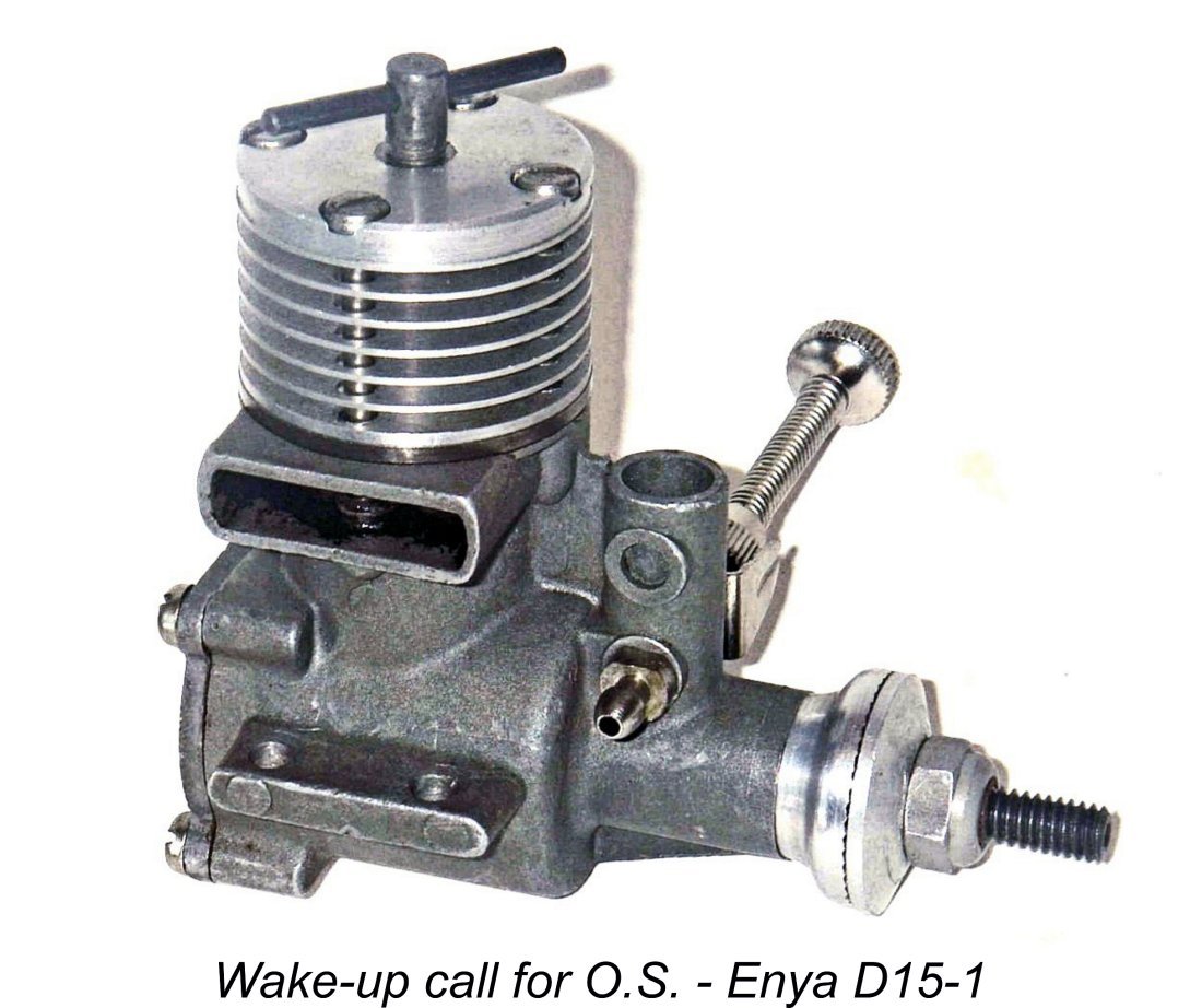
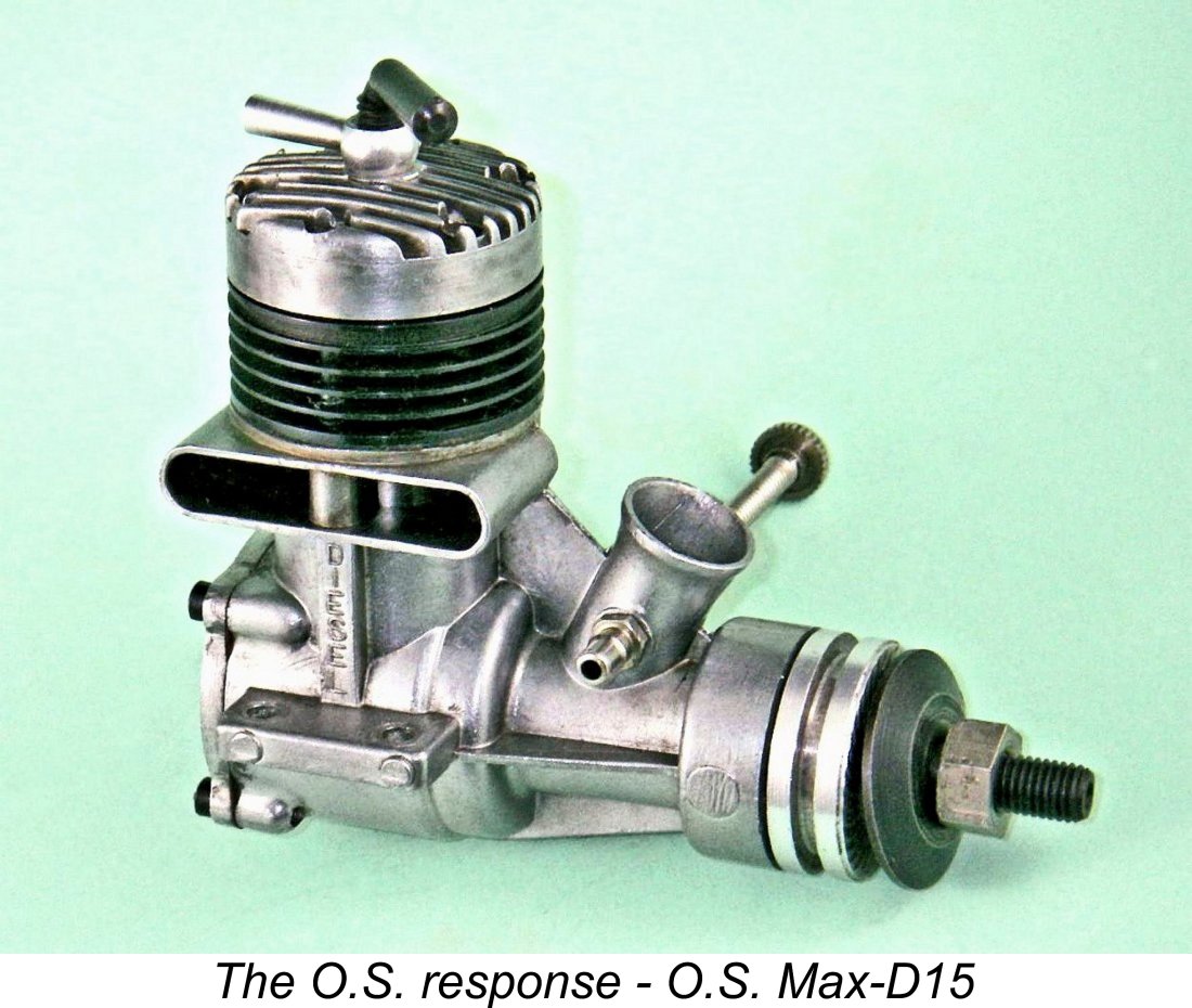
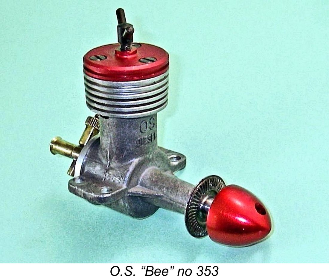
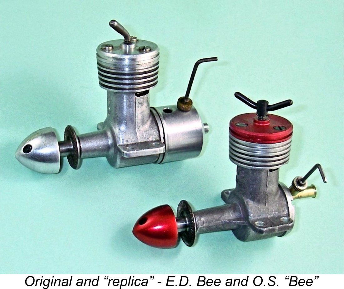
It took the march stolen on O.S. in late 1956 by their Tokyo arch-rivals Enya with the ground-breaking 2.5 cc Enya D15-I diesel (often simply referred to as the Enya 15D) to re-awaken the O.S. company’s interest in becoming involved once more in the field of model diesels. O.S. invariably covered any moves by Enya (and vice versa), hence feeling that they couldn't take Enya's diesel initiative lying down. During 1957 they embarked upon a concentrated development program of their own with the intention of producing a 2.5 cc (.15 cuin.) diesel that would beat anything Returning to our central subject, the accompanying images will confirm that the O.S. “Bee” bore a similarity to its E.D namesake which was very far from coincidental. In every significant way, it must be seen as a straight copy of the British product with a few detail modifications. However, there’s absolutely no possibility of mistaking one model for the other. Even across the room, the handsome red anodizing on the O.S. model’s head and spinner are unmistakable, as are the Y-shaped compression screw, the absence of a tank and the consequently exposed bell-mouthed brass intake tube. A closer inspection reveals even more very obvious differences. The O.S. crankcase is a pressure die-casting which has been very nicely sand-blasted to an attractive matte finish - very different from the E.D.’s gravity die-cast natural finish crankcase. The later examples are clearly The identification of the later examples as a "DIESEL" in Latin characters strongly implies that O.S. entertained visions of exporting this engine to the English-speaking world. Evidently this never happened - there's no record of the engine ever appearing on markets outside Japan. The fact that the original E.D. Bee was already well established in other potential markets probably acted as a deterrent - O.S. would have been going head to head with the original at a time when lingering resentment against Japan arising from WW2 was still prevalent, as was an unwarrantably negative perception of Japanese precision engineering standards. The noteworthy capability of early post-WW2 Japanese model engine manufacturers had yet to be appreciated.
By the time we get to engine no. 323 as well as my own example, engine no. 353, the main bearing has been considerably lengthened and is provided with a pair of bracing webs, one on each side. The crankshaft was clearly lengthened to match. These revised long-bearing crankcases display the previously-illustrated "OS DIESEL" designation. I have an image of at least one additional example displaying these features (see below), but don’t have a number for that unit. At the rear, the O.S. features a turned brass tubular intake venturi having a flared bell-mouthed entry, as opposed to the E.D.’s simple parallel-sided thin-walled steel tube. It is a firm plug fit into the backplate opening but can be set at any desired angle relative to the engine. My late and much-missed Aussie mate David Owen commented that to his knowledge no example of the O.S. “Bee” had ever turned up with a tank fitted - the seemingly NIB example of which David was able to supply the rather indistinct low-resolution photo seen below at the left certainly lacked a tank. No real surprise there, because the bell-mouth flare on the end of the brass venturi would prevent the fitting of a tank that didn’t leak around the necessarily oversized point of entry of the venturi. Moreover, the length of the intake tube is really too short to accommodate a tank, implying that such a fitting was never envisioned. That said, a few examples have shown up with the bell-mouth removed, either to allow the fitting of a tank or just to shorten the engine.
That said, my mate Maris Dislers has pointed out that those decals bear an uncanny resemblance to the "Bee" decals produced by Cox during the 1950's to accompany their various "Bee" .049 glow-plug models. It's entirely possible that someone slipped a set of those decals into the O.S. package seen in David's image. All of these engines, regardless of crankcase style, appear to have borne serial numbers which were stamped onto the right-hand side of the crankcase just above the mounting lug on that side near the front. Two such numbers are visible in the image above at the right. My own long-bearing example bears the number 353. My correspondent Alan Strutt of England reported owning long-bearing unit no. 422, which is the highest number that I’ve yet seen. I also have incontrovertible photographic evidence of a long-bearing unit bearing the number 323 as well as short-bearing examples bearing the numbers 203 and 250. A third short-bearing example appears to display the number 131, although this image is less distinct and the number could possibly be incorrectly deciphered. Any additional confirmed serial numbers which readers can provide would be greatly appreciated!
The aluminium alloy rotor with its kidney-shaped opening registering with a circular intake is straight out of the E.D. design book. With a screw-in backplate, induction timing will be completely dependent upon the annular orientation of the backplate when fully tightened. The induction period provided by the disc valve is of the order of 130 degrees - a very small period for a disc-valve engine. With such a narrow window to play with, some degree of timing compromise is inevitable. I would guess that the engine would probably work best with the backplate positioned to open the induction phase at around 70 degrees ABDC and close it at around 20 degrees ATDC. Most interestingly, upon reassembly my illustrated example checked out at almost exactly those figures - evidently I wasn't alone in my opinion! An earlier opening and later closure would doubtless be preferable, but that’s not possible without modifying the rotary disc. It's possible that the hole location for the intake venturi was marked with the backplate assembled on a trial basis and then drilled in the marked location with the backplate removed once more. The alternative would involve selective fitting of components by trial and error - not an efficient approach. However it was accomplished, getting the timing exactly right for all examples using this assembly on a production-line basis appears to be a bit much to expect. We might anticipate considerable variation in performance between different examples - the precise orientation of the backplate and its associated timing would doubtless have varied somewhat from one example to the next. The Mk. I Series 1 Bee certainly exhibited such variations.
The single jet spraybar is soldered in place in the intake, again exactly like that of the original E.D. Bee. It is located far closer to the backplate than the E.D. component - the absence of a tank facilitates this. In fact, it’s located so far forward that it can’t be positioned with the needle oriented vertically - there’s insufficient clearance between the needle control arm and the cylinder. The needle valve assembly is actually pretty much a direct copy of the E.D. component apart from the use of a split thimble instead of the E.D.’s tiny internal coil spring. That said, I’ve seen images of a few different needle valve assemblies with various examples of this engine. I have no idea which arrangement is the “true” original. Take your pick …….! The intake has a bore of 3.7 mm with a spraybar diameter of 2.5 mm. Reference to Maris Dislers’ invaluable intake choke area calculator reveals that this gives an effective choke area of 2.264 mm2. While this may sound pretty minimal, in reality it appears to be very well chosen for a moderate speed 0.98 cc diesel. Maris’s calculator shows that The compression screw proved to be threaded M3x0.65 - a very unusual metric thread. However, it’s not unique to this model - a number of early O.S. engines featured assembly fasteners having this thread. The company appears to have had both taps and dies of this size on hand during the early post-WW2 years as well as a supply of suitable fasteners. Some of the later spin-off Kyowa models also featured such a thread. Fasteners, taps and dies for this thread appear to be unobtainable today - I’ve searched. A number of examples of the O.S. "Bee" have shown up with single-arm comp screws like those used on the early E.D. Bees. A long-bearing example bearing an unknown number is illustrated here. It’s unclear whether these are original or owner replacements, with the thread perhaps being re-cut to 1/8 Whitworth (a very slightly larger diameter thread having almost the same pitch). Check the threads …………. An Inside Look By now I was becoming really interested in testing the full extent to which O.S. adhered to the dimensions used by E.D. in their original Bee. This required me to continue the tear-down. Removal of the three assembly screws freed the red-anodized head, allowing removal of the cylinder followed by the piston/rod assembly. The next departure presented itself immediately - the three head screws proved to be threaded M3x0.55 (46.16 tpi)! Another really oddball metric thread that appears to have been more or less unique to O.S., contrasting significantly with the 6 BA fasteners used by E.D., which have a slightly smaller O/D of 0.110 in. (2.79 mm) and a pitch of 47.9 tpi. Close, but no cigar ……. 6 BA fasteners rattle about when started into the O.S. tapped holes! Moral of the story - don’t lose or strip those fasteners!! A positive feature was the unusually long threaded portion of these screws which extended below the head, thus being available to engage with the crankcase threads, the full length of which was utilized. The thickness of metal available to secure these fasteners was increased to match on the O.S. by the filling-in of the gaps between the first, second and third fins down. The original E.D. models only had the gap between the first and second fins filled in, thus having a substantially smaller thickness of metal available for drilling and tapping. The switch to the filled-in third gap didn't appear on the E.D. originals until late 1950, seemngly dating the appearance of the O.S. copy to 1951 if we assume that it was indeed a direct copy.
The hardened steel cylinder features twinned exhaust and transfer ports which again follow the familiar E.D. Bee design precisely, hence requiring no elaboration here. Cylinder O/D is 0.527 in. (13.4 mm) as opposed to the E.D.’s 0.532 in. Consequently an E.D. cylinder will not fit into the O.S. case, while the O.S. cylinder is a “rattling” fit in an E.D. case. This fit has to be very close with this design - the crankcase compression seal depends upon it, since there’s no place to install a gasket. Apart from its very slightly smaller diameter, the cast iron piston is virtually identical to its E.D. counterpart. It drives the crankshaft through a turned steel “dog bone” conrod which looks identical to its E.D. counterpart and appears to be case-hardened. The rod engages with a one-piece hardened steel crankshaft having an unbalanced plain disc crankweb, again following the E.D. design precisely. Main journal diameter is 0.2165 in. (5.5 mm). A standard E.D. Bee shaft is 0.219 in. dia., meaning that an E.D. shaft won’t fit into the O.S. main bearing. Even if it did, it would be too short for a long-bearing crankcase like mine. The red-anodized alloy spinner nut engages with a M5x0.8 thread at the front of the shaft - a familiar thread at last! This is fractionally larger than the 2 BA thread used on the E.D., which has a diameter of 4.7 mm and a pitch of 0.809 mm. The various dimensions recorded above seem to confirm that while the O.S. model was dimensioned very closely along E.D. lines, a certain amount of metrication took place. The main exception to this was the backplate thread, which is common to both models. However, with that single exception, there’s absolutely no direct interchangeability of components. One thing that O.S. got absolutely right, on this example at least, is the virtual elimination of any end-float in the crankshaft assembly. As with the E.D., the deeply-serrated steel prop driver is mounted on a very shallow angle self-locking taper at the front of the shaft. When the prop is fully tightened, there’s a minimal clearance of only a few thou between the rear of the steel prop driver and the front of the main bearing housing. Such a small clearance is essential with this design, since otherwise the shaft can shift far enough rearwards to cause the crankpin to bear against the alloy disc valve, which then becomes an assymetrically-loaded thrust bearing during starting or, even more problematically, if the engine is run in pusher mode.
Unless corrected, this excessive clearance inevitably gave rise to the greatly accelerated disc valve wear for which these E.D. models were well known. For this reason I’ve always re-cut the 7 degree (included) female taper in E.D. prop drivers to reduce end float to a minimum, thus preventing the crankpin from bearing against the disc valve. Such a step has the added advantage of slightly increasing the rather marginal length of thread available to mount the alloy spinner nut. I would never run an E.D. Bee or Hornet that had not been adjusted in this way. This was unnecessary with my example of the O.S. clone - thanks, Mr. Ogawa!! The above observation brings up an important point. The quality of construction displayed in this engine is extremely high by any objective standard, totally belying the perception prevailing at the time that Japanese precision manufacturing standards fell well below those in effect elsewhere. I suspect that many observers from England and America would have been quite surprised by this engine's unmistakable quality. I trust that the above description will have confirmed that the O.S. 1 cc “Bee” diesel is a very close copy of the Mk. I Series 1 E.D. Bee. Dare we call it one of the first “replicas”?!? Regardless, it was clear that it would be fun to see if its performance matched that of the original. I could see no reason why it shouldn’t, but there was only one way to confirm this - smell the ether and make some noise! Always a pleasure ...... The O.S. “Bee” Diesel on Test The example of the O.S. “Bee” which I was fortunate enough to acquire is in absolutely pristine condition. As received, all indications were that it had done little if any running - perhaps a factory test run, but no more. Accordingly, it was clear that it would require a normal break-in period before meaningful test figures could be taken.
Still, onwards and upwards! The O.S. “Bee” went into the test stand, where it looked right at home and felt all ready for some hard work following a bit of a break-in. I used an un-nitrated fuel consisting of 35% ether, 35% kerosene and 30% SAE 60 mineral oil. Low-revving diesels (which I expected this one to be) generally do just fine on such a mixture. Since the engine seemed to require a full break-in, I elected to begin with an APC 8x6 prop. The original E.D. Bee tested earlier had turned this at 5,700 rpm - a reasonable break-in speed.
That said, once the settings were established, both controls held those settings perfectly. For break-in purposes, I kept the mixture slightly rich with a reduced compression setting, leaning out and optimizing the settings of both controls for the final 30 seconds or so. The reasons for doing this are fully explained in my separate article on iron-and-steel diesel break-in. The engine turned this prop initially at a speed of around 5,500 rpm - a little down on the original E.D. Bee tested earlier, but the O.S. would doubtless do better with a little more running.
I put a total of 40 minutes running time on the engine in 5-minute runs, leaning out to peak performance for 30 seconds at the end of each run. After this treatment, the engine felt superb, clearly all ready for some hard work. I then proceeded to obtain figures for the same suite of test props that I had used for my earlier test of the original E.D. Bee. Starting and running qualities continued to be excellent throughout the test. The following data were obtained, with the figures for the E.D. being included for comparison. The power curve applies only to the O.S. "Bee".
As can be seen from the above data, the O.S. "Bee" pretty much matched its E.D. progenitor up to around 7,500 rpm, at which point it evidently ran out of breath. Consequently, it didn't quite come up to the level of peak performance of the E.D., topping out at 0.043 BHP @ 7,500 rpm. Nonetheless, it showed itself on test to be an easy starting and smooth running little engine which was built to a very high standard. It would doubtless have served its owners well in general-purpose sport flying applications. I have little doubt that it would make a better showing if freed up through some more running. Conclusion It must be clear from the above discussion that the O.S. "Bee" displayed very little design originality, being more or less a straight copy of the original E.D. Bee with a few detail modifications and some metrication of dimensions. However, it's important to remember that O.S. designer Shigeo The result of his efforts was an extremely well-made and user-friendly rendition of the basic E.D. design that performed to a perfectly acceptable sports standard for its day. Setting aside any unfavorable overseas views of the Japanese people and their manufacturing skills still lingering from the trauma of WW2, any objective reviewer from anywhere else in the world would have found this to be a satisfactory product in every way. I know that I would have been very happy to have an example to use back in the day! The presently-reported range of O.S. “Bee” serial numbers is far too small to allow any authoritative conclusions to be drawn with respect to production figures. Alan Strutt's engine no. 422 bears the highest number yet recorded, but that really doesn’t mean much in the context of such a small sample - it just means (or seems to mean) that at least 422 examples were made. If any reader can provide higher numbers with photographic authentication, please get in touch! That said, the extreme rarity of this engine is such that I would be very surprised indeed to learn that total production exceeded, say, some 500 examples. Even in its native Japan the engine is reportedly very seldom encountered. Since it was evidently never exported during its production period, it is a vanishingly rare engine outside of Japan. I just got lucky, as did a few others ………… _______________________________ Article © Adrian C. Duncan, Coquitlam, British Columbia, Canada First published October 2021
|
||||
 In this article, I’ll be taking a close look at another very ephemeral product of the well-known O.S. company of Osaka, Japan. This is the little-known and very rare O.S. 1 cc diesel which was marketed very briefly in Japan during the early 1950's.
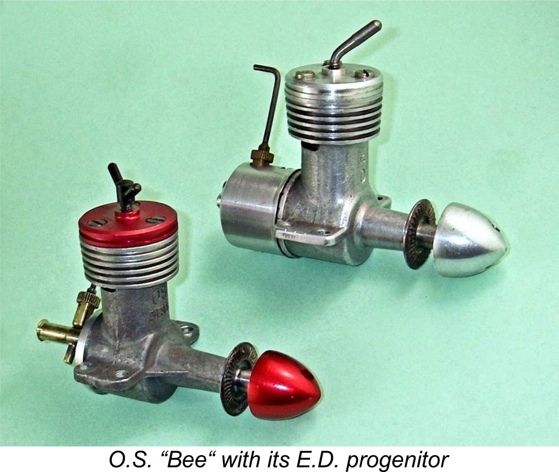
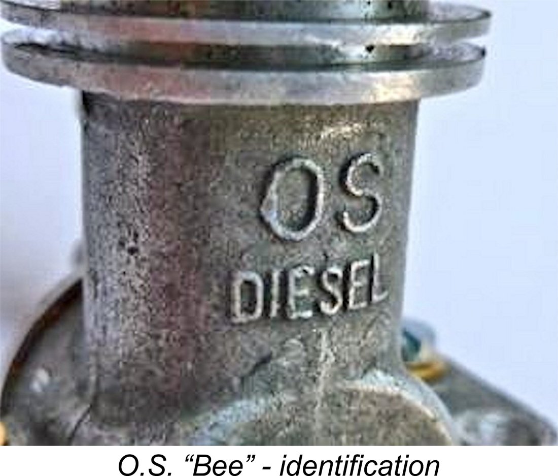 identified on the front as being an “OS DIESEL” (as written) as opposed to the usual form of E.D. model identification - there’s no way that an E.D. case could be used to create a convincing fake O.S. “Bee”. That said, I have seen at least one "O.S. Bee" that was clearly (and extremely unconvincingly) faked using a "sanitized" E.D. case. Caveat empor .............
 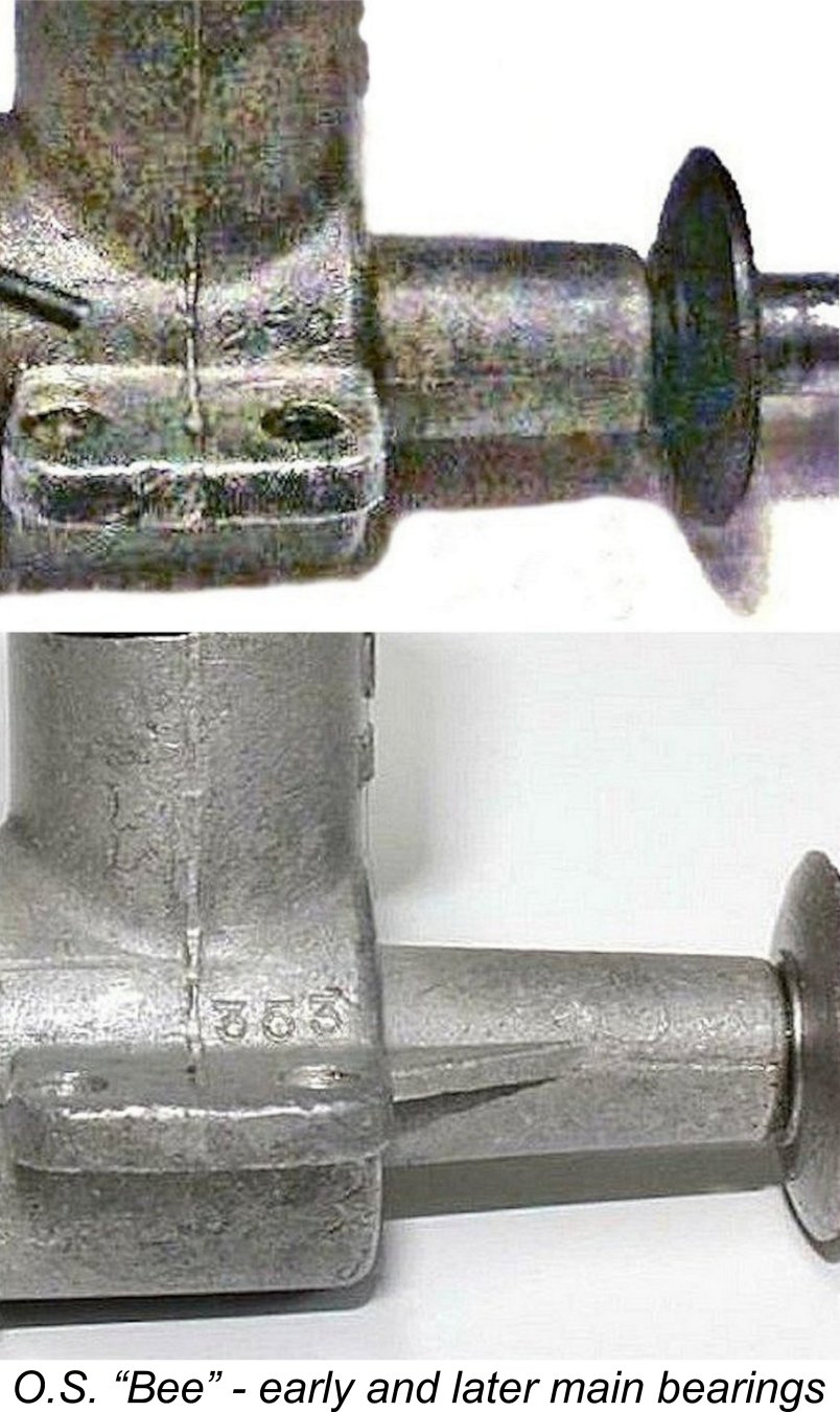 One point which appears to have escaped previous commentary is the fact that two quite distinct crankcase castings were used. Up to engine no. 250 at least, the main bearing housing was quite short, more or less matching that of the original E.D. Bee. Moreover, it followed the E.D. design in being unbraced. It also lacked the previously-mentioned "OS DIESEL" identification on the front of the crankcase.
 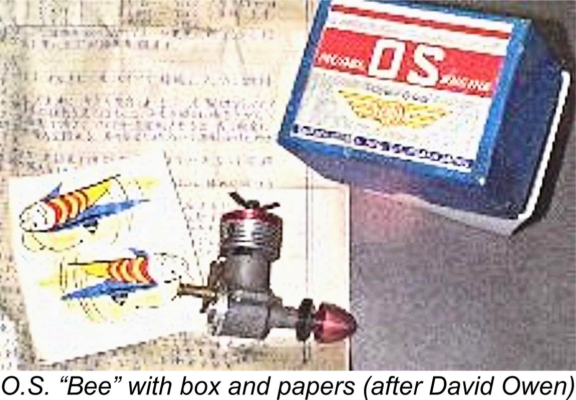 The image at the left also makes it very clear that the O.S. “Bee” was presented as a mainstream O.S. product, complete with the strikingly-decorated red, white & blue box used by the company at that time for all their models, as well as a Japanese-language instruction sheet and a pair of cute “bee” decals. Those decals strongly suggest that the engine’s Japanese name did indeed have something to do with bees! The Japanese word for "bee" is "hachi" (or alternatively "mitsu-bachi"), but that's as far as I can get!
 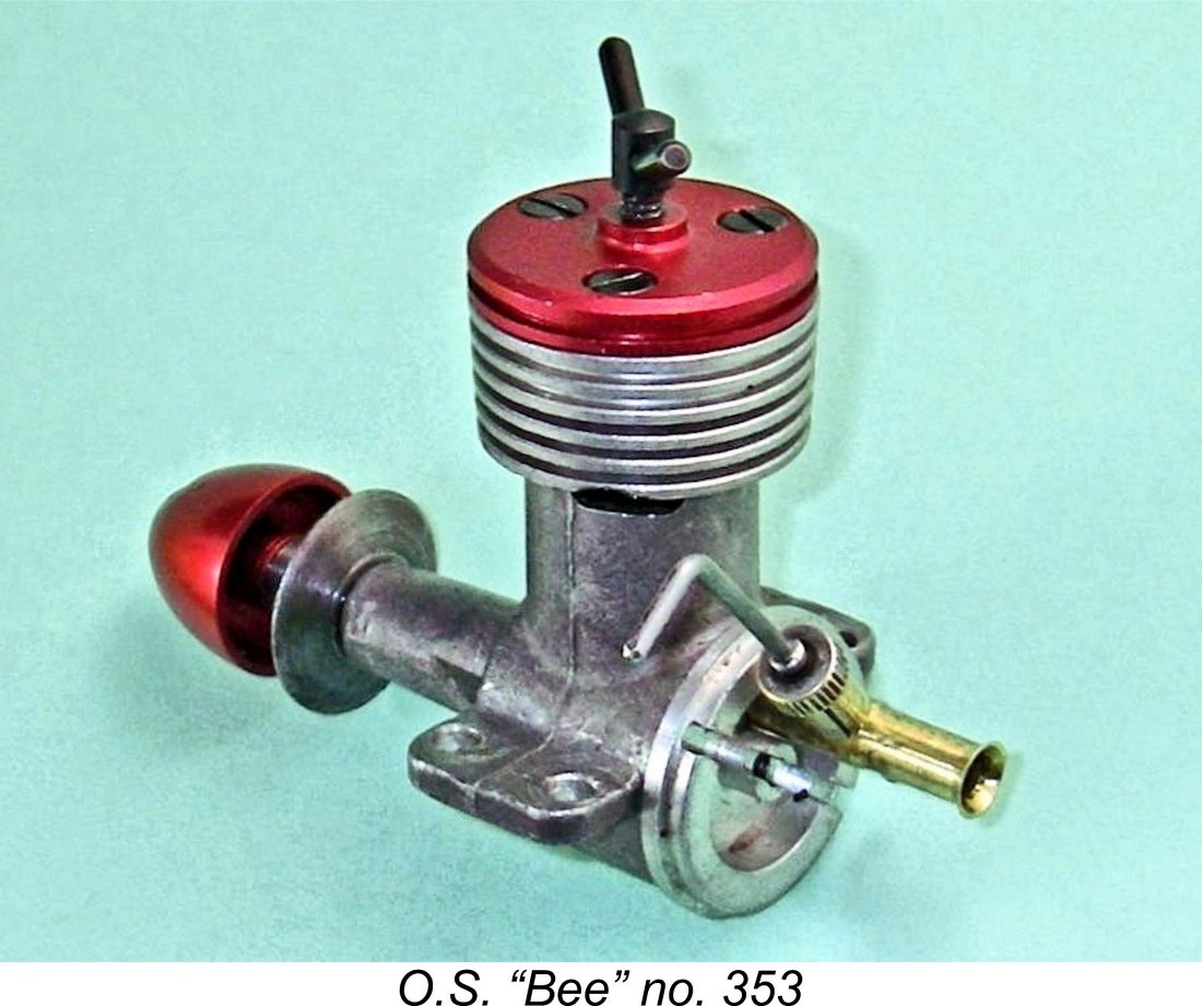 Given my curiosity regarding the extent to which the O.S. “Bee” was a true E.D. clone, I felt that a careful look inside was fully justified. The first stage in the dismantling of the engine was the removal of the screw-in backplate. The backplate thread turned out to be identical to that used on the E.D. - the O.S. component fits into an E.D case perfectly, and vice versa. Its removal immediately revealed a set of internal components which looked like exact copies of the E.D. originals.
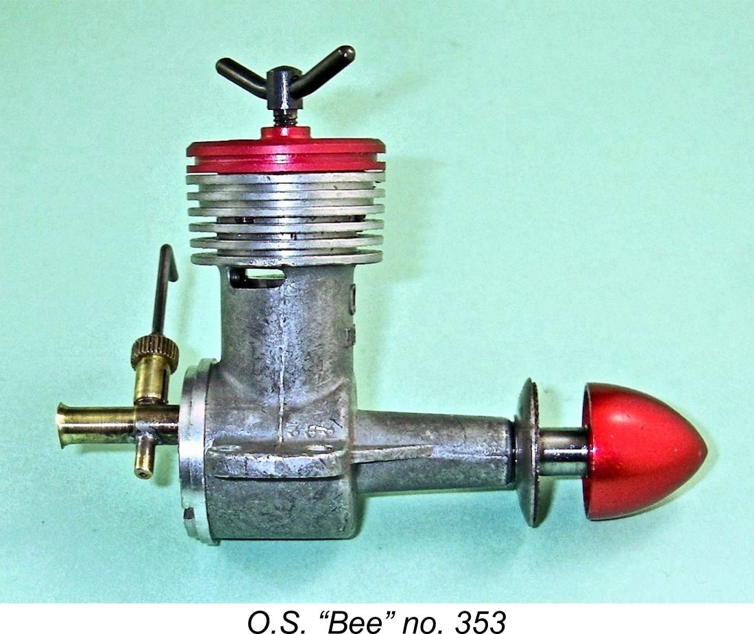 The brass intake venturi is a tight plug fit - almost a light press fit - into the round backplate hole, thus once again following the E.D. arrangement. Unlike the tubular steel E.D. component, it is turned from brass. In addition to the bell-mouth point of entry, it has a slight expansion around the needle valve location. The low shoulder at the front of this expansion locates the intake so as to prevent it from being pushed far enough forward to foul the disc valve - actually an improvement over the E.D. design. However, it must be recalled that the E.D. model was designed to have a tank fitted, which would in itself locate the intake very securely in a fore-and-aft sense.
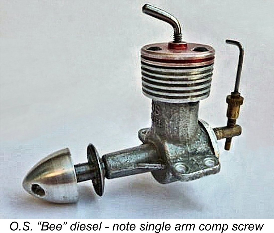
 The bore of the O.S. was carefully measured and found to be 11.05 mm (0.435 in.) as opposed to the 0.437 in. (11.10 mm) used in the E.D. Consequently, E.D. and O.S. pistons are nowhere near interchangeable. By contrast, the stroke of the O.S. was found to be very slightly longer than that of the E.D., being 10.2 mm (0.4105 mm) as opposed to the E.D.’s 0.400 in. (10.16 mm). The figures measured for the O.S. yield a calculated displacement of 0.98 cc which is virtually identical to that of the E.D. - just a very slightly smaller bore and an equally slightly longer stroke based on metric dimensions.
 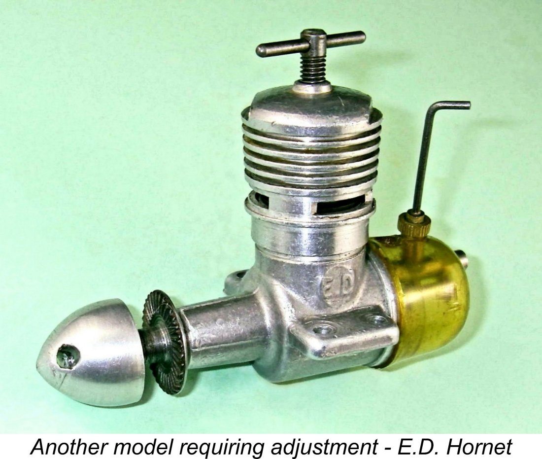 E.D. often got this wrong, routinely assembling Bees (and
 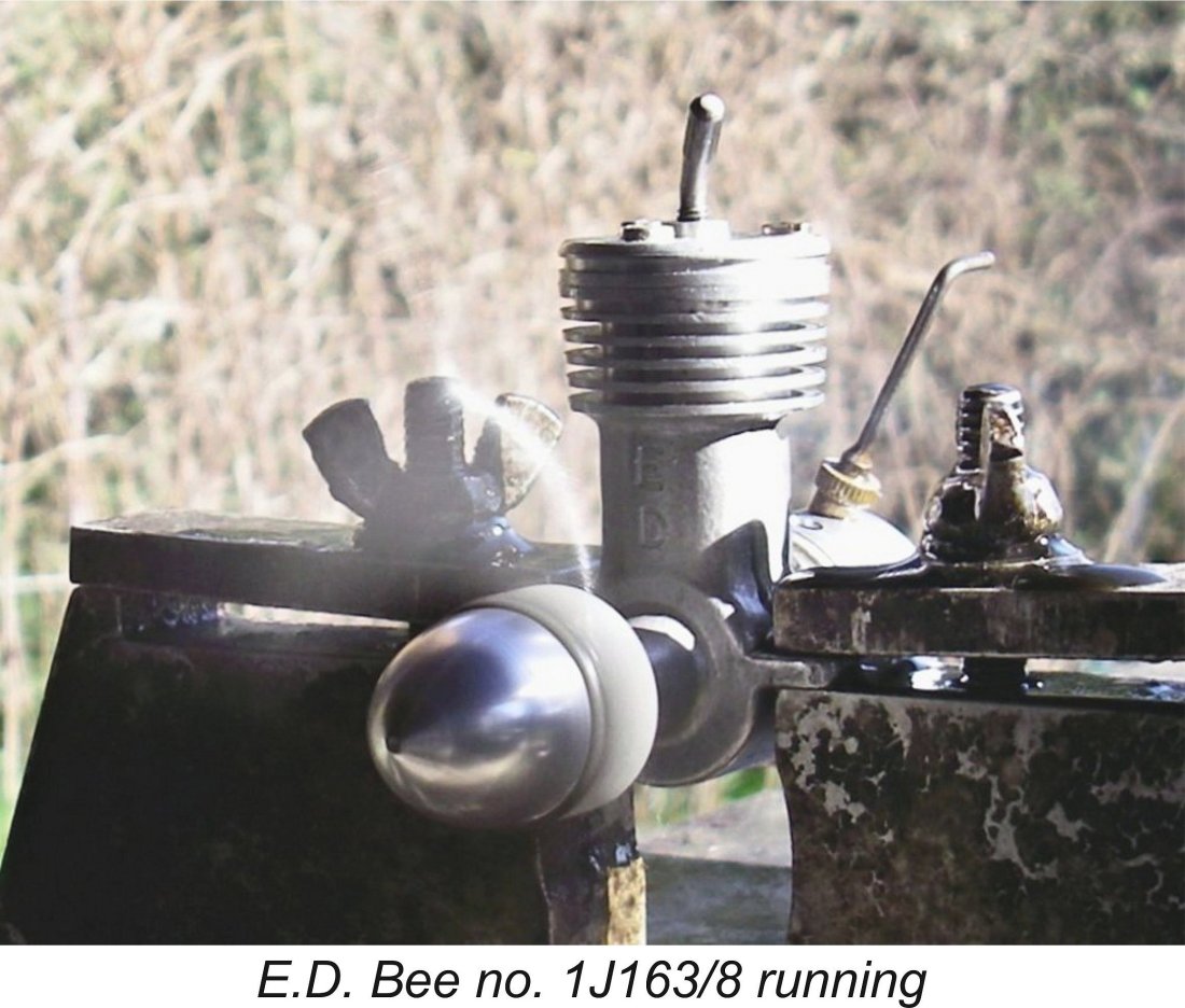 It was quite fortuitous that I already had some test figures extracted earlier from illustrated E.D. Bee Mk. I Series 1 engine no. 1J163/8, which is a very early example dating from September 1948. That unit proved to be an excellent starter and a fine runner, albeit not particularly powerful. I was only able to extract a peak output of 0.049 BHP @ 8,500 rpm, which does not compare at all favorably with the figures of 0.062 BHP @ 10,600 rpm reported by Lawrence Sparey in the
 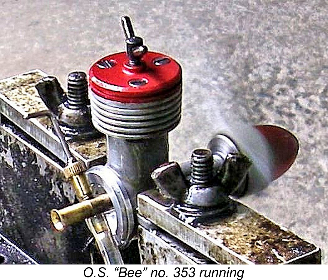 The initial runs with the O.S. "Bee" taught me some important lessons. The engine was undoubtedly a little on the tight side, hence definitely requiring the full break-in that I had anticipated. Even so, it was very easy to start following a small exhaust prime, also running very smoothly with excellent suction. However, I found that the needle valve setting was unusually critical - around a quarter turn went from a little too rich to cutting out! This was doubtless due to the relatively coarse taper of the needle tip. The sweet spot was easy enough to find, but I'm sure that the engine would benefit from a more finely-tapered needle.
 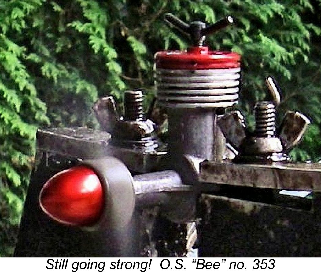 A problem that not infrequently presents itself when running an original E.D. Bee with the tank removed is that of the pressed-in induction tube slipping in its installation aperture in the backplate. This issue never reared its ugly head at any time during my test running of the O.S. "Bee" - the interference fit of the induction tube in the backplate was more than tight enough for ample security. Many years ago I made a very finely tapered steel mandrel that expands the installation end of the E.D.'s steel venturi tube when temporarily pressed in. This restores adequate tightness to the fit of an E.D. carburettor in its backplate. However, such an adjustment was not required in this case.
 Ogawa was the first Japanese manufacturer to tackle the challenge of series-producing a model diesel engine, hence being a full decade behind his European counterparts. How better to get one's feet wet in a new technology than to copy an established and successful model from elsewhere? It's very hard to fault Ogawa-san for taking the approach that he did.
 | |