
|
|
Russian Rarity - the 2.5 cc MK-12S Diesel
Some confusion has arisen from the fact that the same engine is sometimes referred to in writing as the MK-12C. This confusion is purely the result of the fact that the familiar Latin letter S is rendered as C in the Russian Cryllic alphabet - the pronunciation is the same, as in “Sam”. Accordingly, the Russians themselves would have identified the engine in writing as the MK-12C but would have pronounced it as the MK-12S (M and K sound pretty much the same in both alphabets). In reality, the two terms refer to the same engine. I’ve chosen to use the Latin rendering solely because most of my readers are familiar with that script and will therefore pronounce the engine’s name correctly as they read it. It must be obvious that quite apart from the language difficulties, researching the history of an engine from the hard-line Iron Curtain era of the early to mid 1950’s in Russia inherently represents a significant challenge. This was a time during which the activities of the Russian aeromodelling community were kept well and truly under wraps as the Russians strove behind the scenes to develop the equipment and skills necessary to make propaganda gains through success on the International contest field. Until very recently, our best witnesses to what was going on at the time in question were the engines themselves.
The MK-12S was designed by a well-known Soviet aeromodeller of the day named Oleg K. Gajevski (O. K. ГАЕВСКИЙ in Cryllic characters). We are extremely fortunate in that Gajevski wrote a quite comprehensive Russian-language book on model aero engines. This book was published in Moscow in 1958 by the DOSAAF organization which was then responsible for the technical development of Russian aeromodelling. Naturally enough, Gajevski included a good deal of information on his own model engine designs. Thankfully, Peter Valicek had a copy of this book on hand, hence being able to share its relevant contents with me. Through the use of current scanning and translation technology, we were able to extract some very useful information about the MK-12S which came directly to us from the designer himself. I subsequently completed the translation and made Gajevski's full text available in English elsewhere on this website. Before going into a description of the engine, I'll share what we've been able to learn from Gajevski about its development. The MK-12S - Development
The MK-12K was clearly a serious and apparently successful attempt to create a highly competitive 2.5 cc diesel. It featured such refinements as a twin ball-race crankshaft, disc rear rotary valve (RRV) induction, ultra-lightweight reciprocating components (piston, conrod and wrist pin together weighed only 7.3 gm) and a generous 6 mm diameter intake venturi with a relatively sophisticated single-nozzle remote fuel metering system instead of a spraybar. The complete engine weighed only 128 gm (4.51 ounces). The MK-12K proved to be an outstanding performer by the standards of its day. Gajevski entered it in a competition for model engines organized by DOSAAF in 1954, winning first prize for engines in the 2.5 cc category. At the competition, the MK-12K demonstrated an output of 0.357 BHP @ 16,500 rpm using a "special" fuel. I know of no other 2.5 cc diesel regardless of country of origin which could match or even approach these figures in 1954. Unfortunately the achievement of this level of performance came at a price. Gajevski tells us that the MK-12K proved to be a rather fragile and hence undependable design, having a short working life and being subject to a higher than normal incidence of structural failure when pushed to its limits. It was clear that any production version would have to be redesigned to address these issues. The resulting production model was considerably beefed up. While generally following the prototype design layout, it featured far more sturdy working components which pushed the reciprocating weight (piston, conrod, wrist pin) up from 7.3 gm to 10.2 gm. The exhaust and transfer periods were also slightly reduced. The intake venturi's inside diameter was reduced from 6 mm to 5 mm, although the same style of remote needle valve was retained. Overall engine weight was increased from 128 gm to a still reasonable 143 gm (5.04 ounces). This version of the engine entered series production in 1955, apparently being produced at DOSAAF's Leningrad plant (now St. Petersburg). To distinguish it from the As we would expect, the changes made to the production version had a somewhat negative effect upon performance. Gajevski stated that the MK-12S production model was found on test to develop some 35% less power than the MK-12K prototypes, and at a considerably lower speed. In support of his statements, he included the attached comparative power curves in his 1958 book. Even so, the measured output of around 0.230 BHP @ 11,600 rpm. was more than adequate for general-purpose free flight and control line service, particularly when considered in a 1955 context. At that time only a very few British 2.5 cc diesels such as the E.D. Mk. III Racer and the Oliver Tiger Mk. III could beat these figures. Gajevski's efforts somehow came to the attention of England's premier model engine commentator Peter Chinn in early 1956. He devoted his "Accent on Power" column in the April 1956 issue of "Model Aircraft" to a largely philosophical discussion of Iron Curtain engine development. The MK-12K was included, with a very brief description, but there was no mention of the MK-12S, of which Chinn appeared to be unaware. He did quote an unattributed claim of 0.22 BHP @ 9,000 rpm which would seem to apply to the latter version. He also mentioned claims of 0.35/0.36 BHP, which clearly refer to Gajevski's previously-quoted test results for the MK-12K. At this time Chinn was clearly unaware that there were two quite distinct versions of this engine having very different levels of performance. The MK-12S was evidently made in fairly substantial numbers over a period of several years. However, the fact that it was never exported on a commercial basis has resulted in its being a relatively rare engine today in Western countries. I’m very much beholden to my valued friend Peter Valicek for his kindness in making my illustrated test example available to me after first obtaining it from its Ukrainian former owner and then giving it a thorough going-over. I’ll continue by describing the engine as best I can. Because I didn’t wish to disturb the meticulous preparation which had clearly gone into this fine example, I have elected to refrain from dismantling the unit. However, a full description is nonetheless possible. Here goes …………. The MK-12S - Description By the standards of its day, the MK-12S is actually a relatively advanced design. It features such high-performance refinements as a twin ball-race crankshaft housed in a separate detachable front cover; disc rear rotary valve (RRV) induction; and a remote needle valve as opposed to a conventional spraybar. According to the Ukrainian commentator Viktor Khodyeyev in his highly informative 2014 German-language book “Modellmotoren Made in USSR”, a very few examples were produced with a bronze bushing in place of the two ball races, but these were very much the exceptions. I'm very grateful once again to Peter Valicek for supplying me with my own copy of Viktor's very informative publication. To some observers, an initial look at the MK-12S might suggest some degree of design influence from the Webra Mach 1 of June 1953 - the timing’s certainly right. However, in reality the two designs have very little in common. Admittedly, both models feature radial cylinder porting, twin ball-race crankshafts and disc rear rotary valve (RRV) induction, but that’s about it. Apart from the very different external appearance, the cylinder assembly, porting The attached component view extracted from Viktor Khodyeyev's book should help to clarify the following description to some extent. Beginning with the basics, bore and stroke of the MK-12S are the standard Continental figures of 15 mm and 14 mm respectively for a displacement of 2.474 cc (0.1515 cuin.). My illustrated example weighs in at 146 gm (5.15 ounces) - by no means an unreasonable figure for a twin ball-race diesel of this displacement.
The drop-in hardened steel cylinder liner is retained and axially centred by a screw-on cooling jacket which threads at its lower end onto an externally-formed male thread at the top of the crankcase. This arrangement is identical to that seen later on the D-C Rapier diesel from Britain. A very useful touch is the provision of a hexagonal boss at the top of the jacket to facilitate tightening, removal and adjustment. For best performance it would be desirable to have the cylinder exhaust ports aligned with the openings in the lower cooling jacket when everything is tightened down securely. My own engine is set up in exactly this way. The comp screw is thoughtfully provided with a coil spring to encourage setting retention. Cylinder porting follows the E.D. Racer pattern. There are three sawn exhaust slots with three sawn transfer ports located beneath them. Bypass is effected through the 360 degree annular space surrounding the lower cylinder below the exhaust port belt. This system is Measurements taken from my own example confirm that the exhaust ports open at around 112 degrees after top dead centre (ATDC) while the transfer ports open considerably later at around 134 degrees ATDC. This gives exhaust and transfer periods of 136 degrees and 92 degrees respectively, with a lengthy blow-down period of 22 degrees. By way of comparison, the timing diagram included in Oleg Gajevski's previously-cited book which is reproduced here shows that the high-performance MK-12K prototype incorporated exhaust and transfer periods of 150 degrees and 96 degrees respectively, with an even longer blow-down period of 27 degrees. The piston is made of fine-grained cast iron, with a conical crown. It is fitted with a connecting rod milled from light alloy. This drives a one-piece steel At the front, the two ball races which support the shaft are housed in a separate bolt-on die-cast housing. A nice touch is the inclusion of lock washers beneath the heads of the four machine screws which secure this housing. Peter Chinn commented that one of the ball-races fitted to his test example (see below) felt “extremely rough”, which might well have affected his test results. I can only comment that both races in my example feel absolutely first class, although I realize that they may be high-quality replacements installed by a previous owner. The heavily-serrated prop driver is secured to the crankshaft spigot by a split tapered collet in the conventional way. The front assembly is completed by a turned aluminium alloy prop washer and steel prop nut. As stated earlier, the backplate is formed integrally with the main crankcase casting. The rotary valve disc The intake venturi is cast integrally with the main casting. It has an internal diameter of 5 mm. Allowing for the fuel jet which protrudes into the centre of the intake, this gives an estimated effective choke area of around 12 mm2. Reference to Maris Dislers’ very useful choke area calculator tells us that the anticipated minimum speed for consistent running on suction would be of the order of 10,000 rpm. One would objectively expect this engine to operate above that speed in service.
The intake does not include a spraybar - instead, a fuel supply spigot is screwed into one side of the intake, with a thin nozzle extending out to the middle of the venturi throat where incoming air velocities should be at their maximum. The externally-threaded needle is enclosed in this spigot, with a banjo connector to accommodate the fuel line. This is in fact a form of remote needle valve assembly which creates a very free-flowing induction tract. The needle itself has a serrated thimble which is tensioned using a double-sided sheet steel spring. The control arm is attached to the thimble through a short steel coil spring which affords some flexibility to facilitate easy adjustment. These engines bore neither serial numbers nor any form of model identification. However, some of them display a
Although one might question the design of the disc valve mounting spindle and the choice of material for the disc itself, the rest of the MK-12S gives the impression of being a well thought-out and quite capably executed 2.5 cc diesel of its day. The next question becomes - how well does it run? Let’s look into that question next. The MK-12S on Test We have already seen that the designer did not claim any particularly outstanding levels of performance for the MK-12S. Based upon his own tests, Oleg Gajevski cited a peak output of some 0.230 BHP @ 11,600 rpm based on the power curve reproduced earlier. Looking objectively at the engine’s design features, this does not seem to be an unreasonable claim - indeed, I would actually have expected a slightly higher performance from a good example of this unit. Perhaps these figures aplied to the "pre-swallow" units, which had a somewhat lesser performance according to Viktor Khodyeyev.
Fortunately we can draw upon some more persuasive evidence than this! The MK-12S first appeared outside the USSR in 1956, when the noted late English free flight expert, World Champion and engine enthusiast Ron Draper, brought an example back to England after participating in a competition in Russia. He later loaned it to Peter Chinn, who published a test of the engine in the November 1956 issue of “Model Aircraft” magazine. This was in fact the first-ever test of a Russian engine to be published in the Western modelling media. Chinn noted that the MK-12S evidently occupied a somewhat analogous position in Russia to that of the 2.46 cc E.D. Mk. III Racer in England, being viewed as an excellent general-purpose powerplant having a very useful performance. Like the Racer, it was used in a range of free flight and control line applications, including FAI free flight competition. However, Chinn also commented that neither the standards of workmanship nor the performance of the MK-12S were comparable with those exhibited by the Racer.
Nevertheless, Chinn was able to develop a reasonable power curve for the engine. This is reproduced at the left. Chinn found a peak output of around 0.215 BHP @ 12,000 rpm, thus coming very close to confirming the designer's claim. He also praised the engine’s starting and running characteristics. Although by no means a world-beating performance in then-current competition terms, these are actually not unreasonable figures for a series-produced 2.5 cc diesel dating from 1955 and weighing just over 5 ounces. Indeed, it would appear that the engine might have done somewhat better than this had it not been for the rough ball-race and the wobbly disc valve mentioned by Chinn. During my inspection of my own example, I had certainly gained the impression that there was more performance potential in the design than Chinn was able to extract.
So into the test stand it went! For best performance, the designer recommended a fuel mix containing 50% kerosene, 30% ether, and 20% castor oil, with the addition of 2½ % amyl nitrate to the overall mix. Since I wanted to protect my example's wearing surfaces, I replaced some of the kerosene with extra castor oil, ending up with a fuel containing 40% kerosene, 30% ether, 28% castor oil and 2% ignition improver (I use Amsoil Cetane Boost Additive). In keeping with my earlier assessment regarding the airscrew supplied with the engine, I elected to start off with a 9x6 APC prop.
The engine endeared itself to me right off the top by starting with a couple of flicks following a small port prime. Unlike Peter Chinn, I found that a prime was more or less essential for a quick cold start, although the engine re-started immediately without a prime when hot. In that sense it would have made quite a good team race “training” diesel! The best technique for a cold start was to choke to fill the fuel line, administer a small open-port exhaust prime and then flick. Starting was more or less immediate using this technique. Suction appeared to be excellent, allowing the engine to start on the prime and pick up immediately on the fuel line. Once running, the engine proved to be a delight to handle. Response to both controls was very positive without being over-sensitive, while the contra piston proved to be perfectly fitted. Indeed, both controls held their settings firmly at all times. Running qualities were beyond reproach - absolutely smooth and Not knowing how much previous running the engine had done, I put it through a number of slightly rich and under-compressed shake-down runs on the 9x6 prop. I leaned out at the end of each run, stopping the hot engine and then allowing complete cooling before going for a re-start. The resulting full-range heat cycles are essential for a proper break-in, as described in my separate article on iron-and-steel diesel break-in. After this series was completed, I commenced the actual testing, continuing to allow complete cooling between runs. The more full-range heat cycles, the better! During the fairly lengthy test session, I paid particular attention to the swaged outer end of the disc valve mounting spindle. Thankfully the component fitted to my example showed no signs whatever of trying to unscrew itself during this test. Even so, I agree with Peter Chinn’s assessment that a lock-nut would have been a preferable approach to securing the spindle against unwanted rotation. Among other things, it would have made it very easy to adjust the disc clearance. Due to its unfailing good manners, this engine proved to be a real pleasure to test. It also performed at a significantly higher level than indicated by Peter Chinn’s earlier report, even bettering Oleg Gajevski's published figures by some margin. The measured prop/rpm figures are summarized below, along with the derived power curve.
The two WB props are cut-down APC items created and calibrated to fill a few glaring gaps in the range of power absorption coefficients represented by my test set. As can be seen, this example of the MK-12S turned out to develop a peak output of around 0.286 BHP @ 11,800 rpm. That’s much more like the kind of performance that I would have expected following my examination of the engine! It’s clear that there’s plenty of lovely torque on tap. The power developed is considerably in excess of that measured by Peter Chinn, although the engine did peak at more or less the same speed. It must be borne in mind that my test example had been expertly fettled before heading my way - in particular, the piston fit was flawless, the ball races felt absolutely silky smooth, while the disc valve sealed perfectly. It's also one of the supposedly higher-quality "swallow" cartouche examples. I suspect that these factors may have much to do with the excellent performance delivered by my example. In view of these findings, it comes as a bit of a surprise to learn from Peter Chinn that both the instruction sheet and references in various Russian modelling publications cited 7,000 rpm as a “normal” operating speed for this engine. Running the engine at such a speed would squander its full performance potential, regardless of whose performance figures you accept. It clearly needs to be propped for a speed of between 11,500 and 12,000 rpm in the air to give of its best. A wide-bladed 8x6 or a fast 8x7 would probably work very well for control line, while a 9x4 would likely be an effective free flight prop. The MK-12S came through this test with flying colours. No mechanical issues arose at any time, while the exhaust residues remained nice and clear throughout. At no time did any indications of excessive wear on any component present themselves. All in all, a most satisfactory test in every respect! Later Developments - the MK-12V As previously noted, the MK-12S enjoyed a production run of some two years, during which time a considerable number were reportedly made. However, in late 1956 or early 1957 the engine was replaced by a comprehensively reconfigured model designated the MK-12V (or MK-12B in Russian script).
This rather confusing situation led Viktor Khodyeyev to incorrectly designate this engine as the MK-12W in his previously-cited book. In reality, the Russian model identification of MK-12B should be rendered in Latin characters as MK-12V - the pronunciation of both forms is essentially the same. To ensure correct pronunciation, I’m going along with the Latin rendering of the engine’s Cryllic identification letter, as I did with the MK-12S. However, be aware that the engines are identified in Russian script on their boxes as MK-12B units.
The MK-12V was destined to remain in production for several decades, continuing right through the 1970’s. As we might expect from this, it was manufactured in very large numbers indeed. Along the way, it appeared in no fewer than five distinct variants, all of which were manufactured in very large production runs.
The MK-12V followed the design of the Webra Mach 1 far more closely than its predecessor. In particular, the first and second variants were almost exact Mach 1 copies. The crankcases of these first two versions were not anodized and were accordingly only available in a natural aluminum color. The cooling jacket and the propeller driver of these units were anodized red. The manufacturers claimed a greatly enhanced output of 0.257 Kw (0.345 BHP) @ 14,000 rpm for this model. The power figure appears to me to be more than a little exaggerated ………the original German-made Webra Mach 1 couldn't match that ouput!
The crankcase of the third version illustrated above was anodized black, while the cooling jacket and the prop driver remained red. The cooling jacket of this variant had a rather different shape to that of the Webra, presumably to provide some extra cooling fin area. This version was still included in a review of then-current Soviet engines which appeared in a 1973 Russian book on model engines. At that time it was reportedly the most widely-used engine among Russian aeromodellers. My example runs very well and is actually quite well made. The fourth variant dating from around 1975 had a natural finish crankcase and a black-anodized cooling jacket of the same shape as that of the third model. These engines generally exhibited very poor quality and To get these engines to perform properly, owners often had to make some replacement parts for themselves. I had to refinish the crankpin, replace the gudgeon pin and make a new custom-fitted rod for my own operating example, which I have since traded on after getting some good use out of it. In addition, the anodizing of the colored components was generally very sub-standard. Application quality was highly inconsistent, while the color did not last long and could even become faded through the action of the fuel.
Two distinct crankcase casting were featured in this version of the MK-12V. I have no idea which came first or whether the two case styles were used concurrently. The example illustrated above at the left has a conventional cylindrical expansion at the front to accommodate the front ball race, very much along the lines of the casting used in the fourth model illustrated earlier. That seen at the right features an extended front race expansion with a "bulbous" contour to its rear section. I have no explanation for the adoption of this configuration. The two engines are otherwise identical. These variants seem to be significantly better-made than the fourth variant units of my acquaintance - I don't know if this is typical. Both of the illustrated examples are essentially free from major manufacturing defects, and both run very well. Like its predecessor, the MK-12V was supplied packed in a cardboard box along with a special wrench, a length of remarkably crap-quality PVC plastic fuel line, a set of mounting screws and a very comprehensive set of operating instructions. An Indonesian Postcript
The club members wondered if any of their British counterparts might be willing to help by donating a few of their surplus used engines to the Indonesian modelling movement. It's nice to be able to report that a number of British modellers responded positively to this request for support, with a handful of engines being sent to Indonesia to assist the aeromodelling community in that country. In the course of these discussions, magazine staff were made aware of an effort to produce a 2.5 cc diesel in Indonesia to a Russian design. An image of this engine was provided, the cited name being the BOMA 2.5. One look at this image, which was published in the December 1960 issue of "Aeromodeller" as reproduced here, was enough to confirm that this was none other than the old MK-12S under another name!
Mr. Tjong went on to manufacture two more engines of his own original design, the 1.5 cc BOMA 150 and the 3.2 cc T.S 35 models. As far as I'm presently aware, these were the only commencial model engines ever to appear in Indonesia. However, I'm open to being proved wrong ......... Sadly, Mr. Tjong seems to have become a victim of the widespread persecution of Indonesian resident of Chinese extraction which took place in the late 1960's and early 1970's, resulting in many such persons either being killed or exiled to China. My sincere thanks to Swedish reader Sten Persson for providing much of the above information. A more detailed article on the BOMA engines appears elsewhere on this website. Conclusion
The MK-12S would have served very well as a general-purpose powerplant having a good performance to go along with its excellent handling characteristics. Indeed, its handling and running qualities are such that a good example would have been very well received outside of Russia - I would have loved to have had one to use back in 1950’s Britain! Well done, Oleg Gajevski! Examples very seldom appear in Western countries these days. However, they do occasionally show up. Anyone acquiring one of these very pleasing powerplants will really enjoy the experience of ownership! __________________ Article © Adrian C. Duncan, Coquitlam, British Columbia, Canada First published December 2020 Revised August 2021 - BOMA 2.5 info added |
||
 In this article we’ll return to Russia during the hard-line Iron Curtain era to share a look at a relatively rare model diesel from the mid-1950’s. This is the 2.5 cc MK-12S unit, a very useable model diesel built to an original design which appears to have been very well received in its native country. Despite this, it was soon replaced by a more up-to-date but far more derivative design after reportedly being produced in quite significant numbers over a period of several years.
 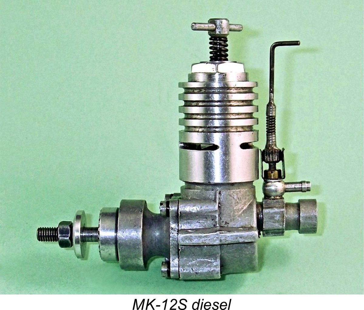 However, in this particular case we're unusually well informed! I'm very fortunate in having a good friend in the Netherlands by the name of Peter Valicek. Not only did Peter track down the fine example of the MK-12S which forms my main subject here, but he was also able to share a treasure trove of original information about the engine from contemporary Russian sources. This article is as much a result of Peter's efforts as it is of mine - without his help I couldn't have so much as contemplated undertaking this project. Thanks, mate!
 Although we don't have an exact timeline for the development of the MK-12S, we do know that Gajevski had completed the prototype design by 1954. In his previously-cited book, the cover of which is reproduced here, he tells us that the intended purpose of the engine was free flight duration and control line competition. The engine first appeared in a short prototype series, at which stage it was designated the MK-12K. The K suffix presumably stood for Competition, which is rendered as
 arrangements and disc valve design in the two models are all completely distinct. The MK-12S follows the
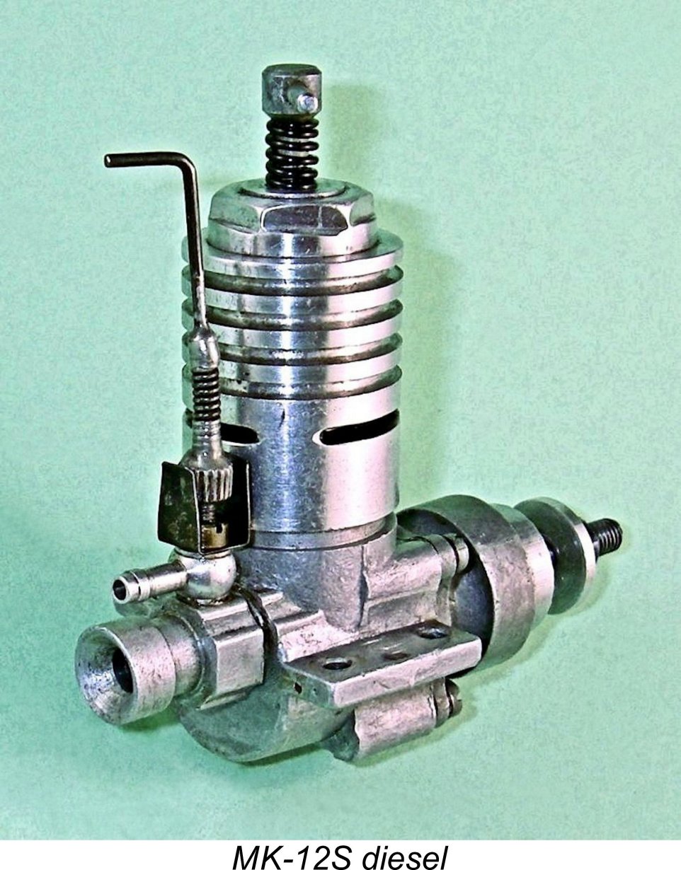
 limited by the fact that no overlap of the transfer and exhaust ports is possible. The unavoidable result is a rather short transfer period, although to some extent this is compensated for by the relatively large combined area of the transfer ports.
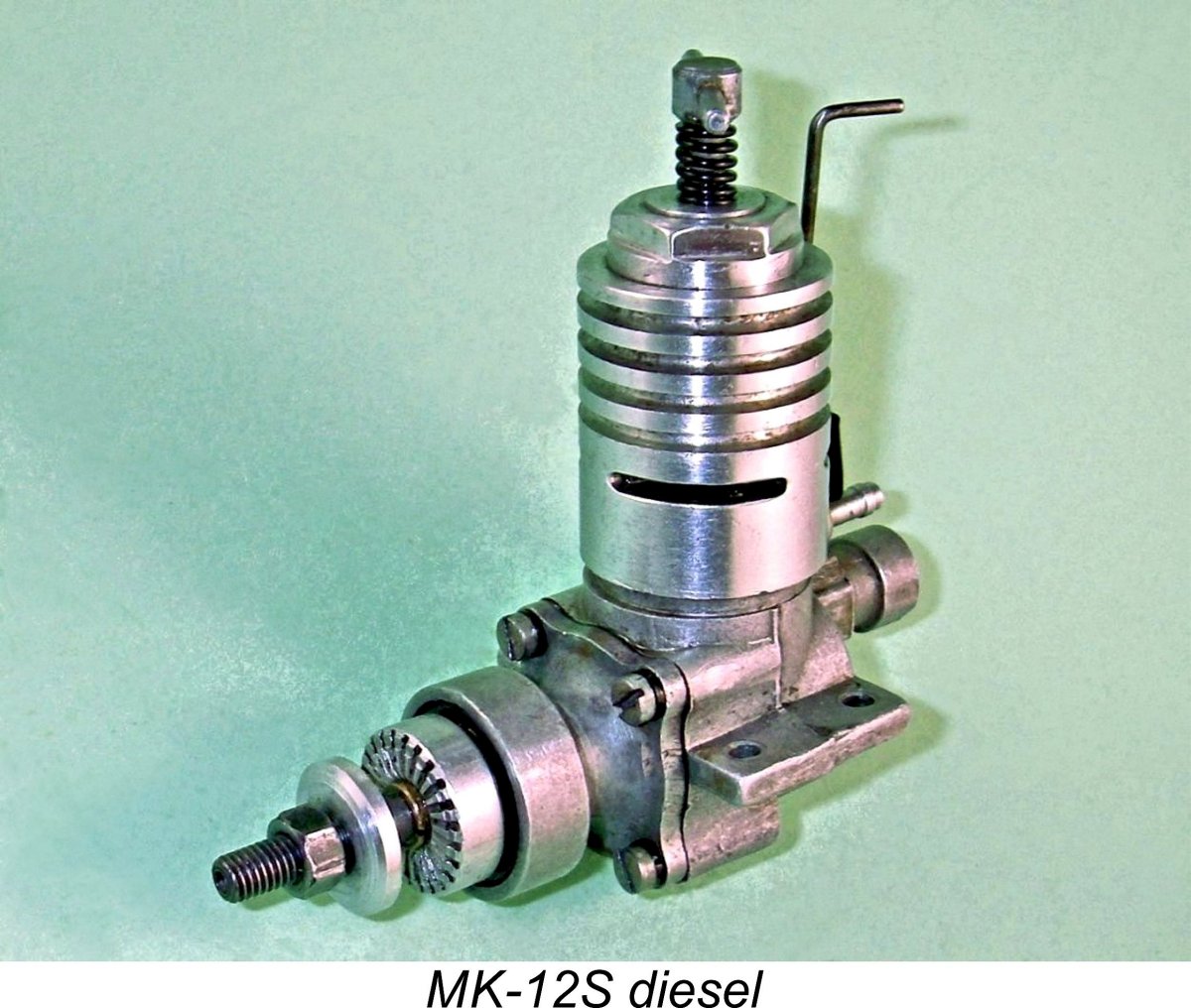
 is machined from aluminium alloy - not the best material choice when used in conjunction with an alloy backplate. The disc incorporates a large thinned area opposite the induction window segment which is clearly intended to create a degree of counterbalance. It is mounted on a steel pin which threads into a tapped centrally-located hole in the backplate. No locknut is used to secure this component - instead, the outer (rear) end of the pin has been hollowed out, bifurcated and then spread laterally to prevent the pin from unscrewing. As we shall see, this is a less than ideal design.
  As measured from my own example, the induction timing provided by the disc valve is relatively conservative. The valve opens at around 54 degrees after bottom dead centre (ABDC) and closes at some 30 degrees ATDC. This gives a total induction period of 156 degrees - not an unreasonable figure for an engine with a free-breathing induction system which is not expected to run at the highest speeds. There is no sub-piston induction.

 The airscrew supplied with the engine was a 230 mm (9 inch) diameter plastic item of unspecified pitch. If this airscrew was in fact a 9x6, then one would expect a typical Continental diesel of this type and era to turn it at around 9,000 rpm on the bench. This expectation appears to be quite consistent with the manufacturer’s performance claim, allowing for airborne pickup.
 Fortunately, I was in a position to check this opinion through a test of my own well-prepared example of the MK-12S. Quite apart from its seemingly meticulous preparation by its former Ukrainian owner and Peter Valicek, it is one of the later better-quality production models bearing the "swallow" cartouche, however imperfectly struck. This being the case, I was expecting a pretty good performance.
 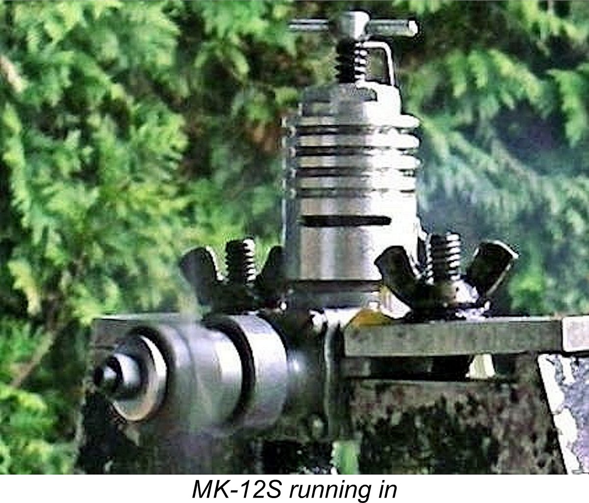 Mounted in the test stand, the MK-12S felt absolutely first class. Compression seal was beyond reproach, with no sign of any undue “stiction” at the top of the stroke - just the necessary light pinch. The bearings too felt perfect - very free running with no trace of “lumpiness”. I was encouraged ………….
  mis-free on all props tested, with no tendency to sag. There was some vibration, but in the test stand at least it didn’t seem to be at anything approaching a problematic level. There was also no problem with the cooling jacket trying to unscrew itself - a not-uncommon issue with engines featuring this type of construction.

 These engines were made in the Moscow Aviation Repair Centre (DOSAAF/MARZ) in very large production runs. Although its main concern was the repair of full-sized helicopters and other aircraft, this plant became one of the world’s major model engine production facilities. It is estimated that between 1956 and 1990 well over 1 million engines of differing types were made at this very prolific facility! Among them were the

 had very short working lives in service.

 The engine was constructed by Pasuruan club member Tan Hien Tjong, an employee of the State-owned P. N. BOMA heavy engineering works at nearby Surabaya, a major port city some 30 miles north of Pasuruan. At this long remove in time, it's impossible to determine whether this was an Indonesian-made replica of the MK-12S, perhaps using dies and tooling somehow obtained from Russia, or whether Mr. Tjong had acquired an inventory of unused Russian-made components for that model and merely assembled them at the BOMA plant, the facilities of which he had authority to use after hours in his spare time. Regardless, it appears that the MK-12S enjoyed a renewed lease on life, however brief.
  Based on my own evaluation, I’m quite comfortable in stating that the MK-12S was an extremely useful engine which must have been viewed very favorably by Soviet modellers during the mid 1950’s. It was also constructed to a generally good standard, although it did embody a few design features which were amenable to improvement. Even these issues could readily be fixed by a capable and knowledgeable owner.
 | |