
|
|
Care and Feeding of Model Diesels
The purpose of maintenance is to maintain the engine's fits at peak levels for as long as possible. This is a particular challenge in a control-line combat setting, which is probably the toughest assignment that any model diesel can draw. In such service, engines are subject to long, hot runs in dirty conditions, along with the repeated ground impacts and dirt ingestion which inevitably result from combat competition. They also have to retain immediate re-starting capability when smokin’ hot. No model diesels lead a harder life!
One of my own contributions to that web-site was the writing of a fairly comprehensive article on the care and feeding of model diesels used in this very demanding branch of the hobby. Since the website has since been taken down, I thought that it would be worthwhile to transfer an updated version of that article to my own website. Accordingly, here are my thoughts on the subject of looking after a model diesel engine which is used in control-line combat. Despite this focus, most of the recommendations set out below will apply to any model diesel regardless of the use to which it is put. Moreover, although the article focuses on the P.A.W. engines, which were by far the most commonly-used motors in vintage diesel combat under our then-prevailing rules, most of the recommendations apply just as well to any model diesel. In re-examining this article, I’ve tried to generalize it as much as possible while retaining any comments that apply strictly to P.A.W. engines. Hope some of you find this useful! Preliminary steps Although the life of an active combat diesel will inevitably be shorter than that of an engine used in a "non-contact" application (such as free flight, R/C or stunt), the owner can do much to minimise the effects of wear and tear, thus maximising the return on his/her investment. It’s an often-overlooked fact that a number of such steps should be taken before the engine has even turned a prop.
If none does, you’re probably OK. If on the other hand you see evidence of debris, then the engine should be subject to further cleaning, very much including the cylinder. Few people bother with this step, but it can add hours to the working life of your engine. One word of caution - there is some evidence that long-term use of an ultra-sonic cleaner may have a relatively minor but nonetheless potentially significant effect upon the smoothness of the races in a ball-race engine. This is presumably due to the vibration of the individual balls against their races. I have never noticed any problems arising from short-term use, but as a precaution I limit the amount of time that my ball-race diesels spend in such a cleaning environment. It doesn't take long to shake out any removable particulates. Next step, and another one that is overlooked with amazing frequency, is to check the end float of the crankshaft. With a well-fitted twin ball-race engine there should be no perceptible end float beyond that permitted by the tolerances applied to the ball-races. If there is a significant degree of detectable end-float (generally with a used engine), it’s most likely due to a front bearing which is an excessively loose fit in its housing and is not located against the shoulder at the base of its recess. It may be necessary to internally shim the bearing recess to eliminate the excess end float and then secure the bearing shell in its housing using some kind of industrial adhesive like low-strength Loctite to prevent skidding of the bearing. By contrast, the shaft in a plain-bearing engine is free to move axially within its bearing. Such an engine should be carefully inspected upon delivery to ensure that the end-float on the crankshaft is not excessive. This is a very common problem with new P.A.W. plain bearing or single ball-race models, for example. The key point is that the rearward movement of the shaft should be constrained by contact between the rear of the prop driver and the front of the main bearing, not by binding of the con-rod or contact between the crankpin and the backplate. Any such contact will have the inevitable effect of sending particles of shaved-off metal through the engine, to its great detriment. The test is - if you push the shaft back as far as it will go with the backplate installed and you can still see a gap between the rear of the prop driver and the front of the bearing, then there's too much end float. An end-float setting of 5 to 10 thou is usually ample, and more than this is excessive. If the end float is too large, the driver can be removed with a small gear puller (the three-jaw variety is best) and a steel shim washer of the correct dimensions fitted to reduce the end float. A steel shim at this location is actually good for engine life, since alloy-on-steel wears far better that alloy-on-alloy. In fact, such a modification is more or less a necessity for any engine that is used in a pusher application, as with certain scale models, for instance.
The really bad thing about this was that the rearward movement in those engines was being limited by pressure applied by the crankpin to the rotary disc valve! Flicking the prop for starting inevitably pushed the shaft back against the disc, resulting in accelerated (and uneven) wear of the alloy disc and generation of harmful particulates. Even worse, if the engines were used in pusher applications or started in reverse (as sometimes happens), the rear disc became the thrust bearing, greatly increasing the wear rate as well as adding a ton of friction. Finally, in a nose-on crash the impact on the front of the shaft was all absorbed by the crankpin acting on the rear disc, to the great detriment of both disc and shaft. This is of equal concern with FRV engines such as the P.A.W. series. With those models having excessive end-float, a nose-on crash will have the effect of "punching" the crankpin into the backplate, often creating a dent in that component and not infrequently bending the con-rod for good measure. I have seen this myself on a number of occasions with engines whose owners ignored my advice in this regard. One can of course easily fix this problem by removing the prop driver using a suitable puller and installing a steel spacer of the required thickness between the prop driver and the front of the main bearing. This is actually a positive step in terms of engine life, since steel-on-alloy wears far better than alloy-on-alloy. However, in the case of the E.D. models a more elegant and less obtrusive fix is available. The best fix here is to remove the driver and mount it in a lathe. One then uses a 7 degree tapered reamer to deepen the tapered recess in the rear of the prop driver to the amount required to eliminate all but 5 to 10 thou of the end float. This eliminates any possibility of pressure being applied to the rear disc by the crankpin. As a side benefit, it also adds to the available prop mounting thread length by setting the prop driver a little further back on the shaft, something which the use of a spacer would not do. The prop mounting thread length on these engines was marginal as supplied, so this alone is a valuable improvement. All of my own E.D. Bee and Hornet models have been modified in this way. I assume that it was cost which precluded the more precise fitting of these components at the E.D. factory. Returning to the P.A.W. and other similar engines, a similar approach can be applied to the correction of excess end float if you have access to a small lathe. You’ll have to measure the taper angle (assuming that the prop driver is taper-mounted) first, and then cut the taper in the prop driver a little at the correct angle to move the driver back to achieve the same objective. However, do not try this unless you have suitable equipment and really know what you're doing! The steel spacer approach is much easier if you don't have a lathe. It is also the only way to go if the prop driver is mounted on splines on the shaft. OK, so we’ve ensured that our new engine is scrupulously clean and is not exposing any of its internal surfaces to rubbing wear of any kind. Are we done yet with advance maintenance? Not at all!
The other thing that you can do in advance of actually using the engine is to provide yourself with the proper fuel. In my book, this means a fuel containing not less than 25% castor lubricant. For a defence of this viewpoint together with full details regarding the subject of model diesel fuels, see my separate article to be found elsewhere on this web-site. OK, so we have our engine properly set up and fully broken in. Let’s install it in a model and start having fun! Here's the next key to getting the best out of your diesel - mount it securely!! The most important thing is to maximize the area of wooden bearer which aborbs the pressure of the mounting bolts and provides the necessary balancing force against the pressure of those bolts. Any "give" here will have the effect of reducing the firmness of the engine's mounting. Many engines have relatively small mounting lugs which lack the area required to spread the load with the bolts really tight (as they have to be). The A-M 25 and 35 are good examples of this. It's a really good idea to make up a set of larger-area mounting plates using aircraft-grade aluminium alloy sheet or similar. These go between the engine's mounting lugs and the surface of the engine bearers. In combination with the use of blind nuts and high-tensile mounting bolts (preferably Allen-head), this assures a really firm mounting. Failure to secure such a mounting can drastically affect engine performance. The creation of unsigntly witness marks on the upper surfaces of the mounting lugs can be minimized by the use of steel washers under the heads of the mounting bolts. In many First, we should do what we can to minimize the possibility of the needle valve being broken in a crash. A good first step is to shorten the handle end of the needle itself. In addition, if the engine has a separate plug-in or screw-in venturi we can set the venturi angle so that the needle is angled back as far as it can be without actually making contact with the crankcase. This will greatly reduce the tendency for the spraybar to break in a crash. If you’re using a P.A.W. engine, don’t over-tighten the venturi set screw since this can distort the venturi bore. Also, a slightly looser fitting allows some "give" in a crash, further reducing any tendency towards breakage. But always check the set-screw after a crash!! The needle valves of engines which do not have a moveable venturi can still be protected through the use of a stabilizing plate which is secured by the engine mounting screws and is drilled through to allow the needle to be installed in the spraybar. Such The next issue about which something can be done in advance is the potential for dirt ingestion in the event of a crash. To minimize this possibility, we can use a flexible "dork tube" (a simple length of silicone tubing) fitted to the venturi intake and secured with a small ziplock fastener or thin wire. This should extend some half-an-inch beyond the end of the venturi. The idea is that it will bend over the end of the venturi in a crash, temporarily closing it off and hence minimising any tendency to ingest dirt in the crash. Sorry experience has proved this to be a very effective measure (although it does nothing for the poor old model!). The above image of a P.A.W. in a combat model shows the idea very well. So much for what can be done in advance to maximize our engine’s potential for enjoying a long and productive life! Let’s now look at measures that can be taken while the engine is in use to contribute to that goal. Operational considerations The first thing that we can do while using the engine in the field goes right back to my earlier advice in relation to break-in – use the proper fuel! The most important thing is an adequate castor oil content. Apart from promoting longer engine life, a sufficient proportion of this lubricant also contributes enormously to hot re-starting capability by maintaining a good compression seal even under very hot conditions. This is why on a really hot day the addition of a little extra castor oil can work wonders! To learn why castor oil is unrivalled as a model diesel lubricant, see my earlier article on model engine lubricants to the be found elsewhere on this web-site.
For this reason, over-compression and lean runs should be avoided like the plague! If you detect signs that this is happening, the model should ideally be ditched immediately to get a re-set of the controls. Running in the overheated or overcompressed condition will wear out the rod bearings in no time flat! Every combat pilot needs to become expert in the noble art of non-destructive ditching of a distressed model on a grass surface during pre-competition testing! Further evidence of the engine’s formerly-distressed condition will be observed upon landing in the form of an ominously black coloration to the oil residues deposited by the exhaust. Of course, the ditching option is not open to you with a stunter or scale model. The best course in those cases is to make your first test flights with a greatly under-filled tank. That way, if you are in an over-compressed or too-lean situation, you won’t be there for long! Once the correct setting is established, you can confidently take off with a full tank. Those test flights are important – use them wisely! Now we come to perhaps the most commonly and even flagrantly ignored factor in the maintenance of a model diesel engine, particularly one used in combat service. An engine which is known (or strongly suspected) to have ingested a significant amount of dirt in a crash should not be re-started until it has been flushed out thoroughly with raw fuel or some other cleaning liquid (I use kerosene). Not a big deal if you're just testing, but if you're in the middle of a close match with a seriously mud-balled engine, you have to decide on the spot if the potential damage to your engine is worth the potential match win. And make no mistake, the damage that we're speaking of here can be considerable! For my part, I usually decided in favor of preserving my engine – there were always other matches! This is no joke - dirt can quickly ruin both the bearings and the piston fit. Extreme cases require at least removal of the backplate for cleaning, so that the induction system can be back-flushed. On some engines with unbushed plain bearings (such as the widely-used PAW BR models), particular attention also needs to be paid to the gap between the prop driver and the front of the main bearing. The shaft runs directly in the aluminium case at the front end, and any dirt entering the bearing quickly turns the soft case material into a very efficient lap, wearing out the shaft journal in very short order! If a lot of dirt has apparently got in there, the shaft will have to be removed for cleaning.
So the flying’s done, and you’re ready to return home with your models and engines. You’re by no means done yet!! First, some fuel residuals are quite corrosive. If you're using castor oil, you're way ahead of the game since castor oil is an extremely efficient corrosion inhibitor. Regardless, one should always inject some after-run oil through the venturi following a session, and the engine should then be turned over to distribute this oil throughout the working surfaces. There are a number of fluids that work well for this purpose – I use air tool oil myself, but automatic transmission fluid and gun oil are also good. This step is particularly important if the engine will not be used for some time, since it reduces the tendency of the castor oil residues to "gum up" the works and makes starting easier the next time out. For my own part, my usual practise with an engine that I know I won’t be using for a while is to remove it from the model, soak it for a while in Varsol (an industrial solvent) and then give it a short session in the ultra-sonic cleaner using methyl hydrate (aka methanol) as the fluid medium. Why methyl hydrate, you ask?? Well, for one thing it dissolves any remaining castor oil residue, thus preventing gumming-up in storage. But mainly it’s because of one of the major criticisms levelled against model diesels by fellow residents of one’s home – “the smell”!! There’s no denying the fact that a recently-run diesel has a distinctive aroma – one which I personally love but which others don’t appreciate. An engine rinsed in methyl hydrate after its Varsol bath generates no detectable odor once dried out and oiled – you can have it anywhere in the house without causing offence. A shot of air tool oil, flip it over to distribute the oil, and your engine will remain odorless and completely free to turn over for years!! I should know – I’m sitting in a room full of them as I type this! If I plan to use the engine and model again in the relatively near future, I leave the motor in the model. However, in such a case I always brush some kerosene over the outside surfaces since this minimizes the build-up of baked-on castor gum over time. It also helps to keep the cooling fins clear so that they function as intended by cooling the motor in flight. Dirt-packed cooling fins do nothing to help cool your engine – definitely worth keeping clear! I also inject some straight kerosene through the tank and out through the spraybar (with the needle removed) to eliminate any potential gumming and consequent blockage of the fuel system. Dismantling Model Diesel Engines My first piece of advice in this area is – don’t do it, unless it's absolutely necessary! Once an engine is fully broken in, any disturbance of the parts will inevitably result in them being re-assembled in a fractionally different relationship to one another. As a result of this, some of the benefits of a careful break-in may be lost. There is also the potential for the introduction of dust or dirt unless conditions of absolute cleanliness are maintained. At the very least, there will be a short-term period of accelerated wear while the parts get re-acquainted. So the first and best advice that I can give you is - follow the old dictum of "if it ain't broke, don't fix it!"!! This said, even the best cared-for engine will inevitably require some replacement parts at some point. The most common replacement requirements in my extensive experience are the con-rod and wrist pin. This is simple wear and tear given the very high loadings under which these components operate. I have also needed to replace the ball races on a few engines, probably due to dirt ingestion during a combat match where adrenaline overwhelmed common sense and I decided to go straight back up (see above!!). At some point, too, the engine may require a rebore when the piston fit becomes too slack for good starting. Now, here’s my next best piece of advice. Unless you really know what you are doing (as opposed to merely thinking that you know, which is a very different thing!), I strongly recommend that you return the engine either to the manufacturer/supplier or to a recognized expert with established credentials in this field for all repairs requiring complete dismantling of the engine. As an example, the repair service offered by P.A.W. is second to none – I've used it myself in the past with complete satisfaction. This is a serious issue, make no mistake! Over the years, I’ve seen a depressingly large number of engines that have been seriously damaged or in some cases ruined by ill-informed attempts to effect repairs or make modifications without the necessary know-how or tools. In many instances, the damage results from ill-advised or uninformed attempts to "tune" the engine to extract more power. Incorrect reassembly is another all-too-common occurrence. The most inexcusable "tuning" efforts in my experience are those applied to engines which are long out of production and are in fact collectible classics. I once sold a used but still complete and original Mk. II Rivers Silver Streak to a fellow modeller who shall remain nameless. He decided that the Rivers could be improved upon and believed (wrongly) that he knew how to go about this. He proceeded to butcher the engine in a totally uncoordinated and ham-fisted manner, resulting in an engine which was less powerful than before and which had lost all of its former value as a collectible. Sad .............. It was to prevent abuses of this sort from arising that our inaugural rules for the Pacific Northwest Vintage Diesel Combat event which was mentioned earlier specified the use of unmodified plain-bearing or single ball-race engines. This resulted in pretty well everyone using the PAW 249 BR single ball-race model. This was fine with us, since we wanted to keep costs down and level the playing field.
Like everyone else, I also used P.A.W. powerplants. However, too many participants chose to ignore all of the above freely-shared advice on set-up, break-in and maintenance. As a result, I soon ended up owning the fastest and most consistent P.A.W. BR models in the area, despite having done nothing to modify them – I merely treated them right! They would pull the largest and most manoeuvrable models around at the speed limit - in fact, I sometimes had to fit a "dud" prop to stay within the limit. Sadly, some people saw this as giving me an unfair advantage. Since I had a bit of a reputation as a tuner, they assumed that this was what I was doing, in contravention of the rules. When challenged, and against my own advice given earlier, I tore the offending engines down to demonstrate their stock condition. I also allowed people to fly with my own fuel, thus proving that there was nothing magic in my tanks. Despite this, the acrimony swelled to the point where I was more or less openly accused of cheating in some undetectable manner!! The critics simply couldn’t or wouldn’t accept that it was their own failure to manage their engines properly that gave rise to their inferior performances. I mention this unhappy interlude here solely because in my opinion there could be no better testimonial to the effectiveness of the measures set out above, which were the sole secret of my success. However, this sad situation killed my enthusiasm for the event, causing me to leave in fairly short order. After this, the rules were changed to "run what ya brung", after which the event degenerated into a free-for–all in which all that mattered was winning, with fun and sportsmanship playing third fiddle if they were even on the stage. I was very happy not to have taken part, and the event didn’t last long thereafter. Why can we never seem to overcome our need to win at all costs and focus instead on just having fun?!? Life's too short ............ For those of you involved in events where tuned engines may be permitted, I can only say that, while my own experiments have shown that it is certainly possible if you really know what you’re doing to tune a P.A.W. or any similar engine for measurably greater performance, there can be a cost in terms of reduced flexibility, consistency, fuel economy and ease of handling. And that’s if the work is done competently - many of the "tuning" efforts that I’ve seen by others have resulted in a motor that is neither user-friendly nor consistent and runs little if any better than a good stock motor - sometimes worse, in fact! I’ve always found that a well-treated stock motor works just fine in the right model for most purposes and strongly recommend that you follow suit. If you really want a well-tuned motor, take it to a recognized expert!
Another good piece of advice is – do as much of the work as possible over a catch tray placed on the workbench. This can be vital in preventing the loss of small components (screws, etc.) which may inadvertently be dropped as the engine comes apart. In case you do manage to drop something, a magnetic pick-up unit works great for recovering small screws and the like, provided of course that they're magnetic. A hand-held metal detector is also a useful tool, particularly for finding small dropped metal components like needles or prop nuts in the field. The most important factor is cleanliness. Great care must be taken to keep dirt and other potential abrasives out of components such as ball races and rod bearings. All parts should be scrupulously cleaned during the re-fitting and re-assembly stages in particular. The first step is generally to remove the backplate. When doing so, please use the correct removal tool and avoid marring the component. Far too many engines are ruined as potential future collectibles by ham-fisted tinkering at this stage!
If the engine has screws to retain the cylinder, do not lose these screws – in many British engines such as the P.A.W. and Oliver models they are a British Association (BA) thread of a type not found much any more outside Britain. If the engine is a Continental or Japanese model, the threads will likely be metric. Replacements may be hard to find! That said, if you do lose a screw or find that one is damaged to the point that it requires replacement, PLEASE don’t re-tap the threads to some non-standard size, since that prevents the engine from ever being restored to original condition in future. Long-term conservation of these engines is important! Replacements having the correct threads are available or can be made – it just takes a little more effort, that’s all. OK, so the cylinder screws are now out and safely stored for later re-assembly. If the engine has a separate slip-on alloy cooling jacket (like a P.A.W. or Oliver), that component may now be removed. However, do not disturb the actual cylinder itself at this point! Before you do that, mark the front of the cylinder permanently at the top with an engraving tool or a small Dremel grinding bit. It is essential that all parts be re-assembled as closely as possible to the original configuration if accelerated wear is to be minimised. Clear marking is an absolute necessity if this is to be achieved.
Now, before you unscrew the cylinder in one of these designs, make sure that the piston is at bottom dead centre and is completely free to move within the cylinder! If it is located at any point within the "sticky" portion of the bore, usually around top dead centre, or if it is gummed to the bore by castor residues (a common issue with long-disused engines bought on eBay), twisting the cylinder out of its threaded socket in the crankcase will of course twist and ultimately break the rod. I've seen the effects of this far too often - be warned!! Returning now to the P.A.W.-style engines with cylinders retained with screws, the cylinder can be removed once it's been marked for re-assembly. Now, before removing the piston/con rod assembly, mark those components too for correct re-assembly. If I intend to re-use the same con-rod, I usually mark the rear of the con-rod to ensure its correct replacement, using a felt pen or a hand-scriber. I also mark the rear of the piston crown. However, if your engine is a P.A.W., note that there is already a punch-mark near one edge of the piston crown directly above one of the wrist pin bosses. This punch mark is critical in these engines - the piston must be replaced with the punch mark towards the rear of the engine (not the front, as far too many poorly-informed "tinkerers" seem to think!). Why is this so important?? Very simple - the two wrist pin bosses are not formed at the same diameter. They are both drilled through at pre-reamer diameter (a fraction less than their final diameter), after which they are reamed to size from one side of the piston (the side with the punch mark). However, the key here is that the reaming stops before the bosses are both reamed right through. As a result, one of them (the one with the punch-mark) is a light press-fit with the gudgeon (wrist) pin, while the other is not reamed right through, causing the pin to tighten and finally stop when pressed into place from the punch-mark side and wedged into the short un-reamed section. This means that the gudgeon (wrist) pin has to be removed and installed from the marked boss which is reamed right through. When re-installed, it must be pressed into its final location against the increasing resistance of the other boss that is not reamed right through. Make sure that the piston wall into which the pin is being forced (the side without the punch-mark) is very well supported during this process, otherwise piston distortion will inevitably result. Now here’s the very tangible key to the reason for all of this – the lower cylinder wall at the front is largely taken up by a very large bypass/transfer flute between the two exhaust ports. If the gudgeon pin were free to emerge from the front piston boss, it would foul this flute and score the cylinder bore. So the piston has to be installed with the tighter (unmarked) piston boss at the front. The pin could theoretically move rearwards to emerge from the less tight (marked) piston boss, but there’s no bypass/transfer flute at the rear for it to foul. The rear cylinder wall will in fact keep it in place. The net result of all this is that if you have to remove the gudgeon pin from a P.A.W. (as you do to replace the rod – a not uncommon requirement), you must do so by pressing the pin out towards the side of the piston with the punch-mark. Upon re-installation, the pin must be installed from the side with the punch-mark. Moreover, that side must be placed at the rear when the engine is assembled. Hope this is clear! Remember, this applies only to P.A.W. engines or those with similar bypass/transfer arrangements. When it comes to pressing out the gudgeon pin to replace the con-rod on a P.A.W. motor, the key requirement is to avoid distorting the piston. The best method is to use a drill press with a suitable mandrel (a steel or alloy rod of slightly less diameter than the gudgeon pin) to press it out. I generally place the piston on a flat piece of hardwood with a hole drilled through it at slightly greater than gudgeon pin diameter. The emerging pin slides into this hole as it is pressed out. Remember - press the pin towards the side with the punch-mark! If you do this right, it doesn’t actually require much force. I have yet to distort a P.A.W. piston using this method. The same process in reverse can be used to press the pin back into the piston with the new con-rod installed, but be very careful not to go too far! Note that the P.A.W. rod too is a one-way fit - the front of the big end bearing on the rod has a small chamfer incorporated, and the big end oil hole must be correctly oriented. So carefully note the way the rod is fitted before attempting to remove it from the piston, and re-fit it or its replacement in the same orientation. I often photograph the components prior to disassembly in case my memory fails me (I'm at that age!). If you are replacing the rod, use a new gudgeon (wrist) pin as well. A loose top bearing is often as much a reflection of wear on the wrist pin as of the rod eye, and wrist pins are cheap anyway! In cases when a significant amount of dirt has been ingested, removal of the crankshaft may be necessary. Staying with the P.A.W. for the moment, the prop driver fits on a simple taper on the front of the crankshaft - there is no split collet. Also, the shaft of a single ball-race model like the BR model is a sliding fit in the inner race of the rear ball bearing. Hence the shaft can be removed simply by pressing it out from the front using a machine vice (not a hammer!!). Always protect the jaws of the vice with a firm non-marring (non-metallic) material to maintain the rear sealing surface onto which the backplate will be tightened upon re-assembly, otherwise you'll lose the vital crankcase gas seal. I use a patch of thick leather. The same approach works for many engines other than P.A.W.’s – it all depends on the particular construction of the engine in question. Some models require the use of a puller to remove the prop driver before removing the crankshaft. If you have to remove the rear ball race, first heat the case in an oven to around 200 deg. C or so (no hotter!). Often a sharp rap of the rear of the heated case on a non-marring surface (wood or similar) will cause the bearing to simply drop out. Failing this, you may have to force it out using light pressure applied with a suitable tool. Be very careful not to mar the plain bearing surface immediately forward of the rear ball race while extracting it, otherwise you may lose all that lovely in-flight fuel suction! The front ball-race can be pressed out from the rear since its I/D is less that the diameter of the main journal, thus allowing the passage of a suitable mandrell through the bearing from the rear. Again, apply a little heat to ease this process. The engine is re-assembled in the reverse order, making absolutely certain that all parts are re-installed in the correct orientation. This is where your earlier marking pays dividends. As stated earlier, cleanliness is paramount at this stage. I always clean all parts (apart from ball races) in an ultrasonic cleaner filled with kerosene prior to assembly. To clean the ball races, I simply spin them in kerosene. Oil all parts as they are re-fitted, and flush out the entire engine once assembly is complete. A little storage oil, and she's as good as new and all ready for more work! Treat the re-assembled engine as a new motor for at least the first 4 or 5 runs if you want to maximise engine life. A final word of warning - do not over-tighten the assembly screws! The BA and metric threads used in many British and most Continental and Japanese engines respectively simply won't take all that much torque without stripping. Tight enough to stay secure in service is tight enough! Again, I do not recommend that you dismantle any model diesel unless this has become absolutely necessary and you truly know what you are about. But adherence to the above steps will help to ensure a successful rebuild if this is unavoidable. Good luck!! ______________________________ Article © Adrian C. Duncan, Coquitlam, British Columbia, Canada First published August 2015 |
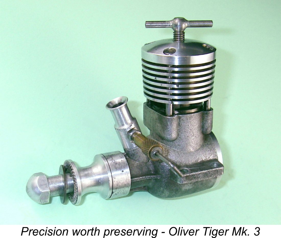 Model diesels, like other model engines, are not toys - they are in fact examples of miniature precision engineering and need to be treated as such. In fact, the required standard of fits, finishes and tolerances for a model diesel to perform well is substantially higher than that required for many "full-sized" machines.
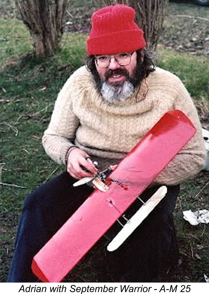 Some years ago I was actively involved in a serious effort to re-establish vintage diesel combat as a strictly-for-fun event here in the Pacific Northwest. Although the event eventually died out, mainly as a result of too many participants losing sight of the fact that the intended motivation was having fun as opposed to merely winning, it was great for the few years during which it flourished! Full documentation of our efforts was accessible for many years on the now-discontinued Pacific Northwest Diesel Combat website.
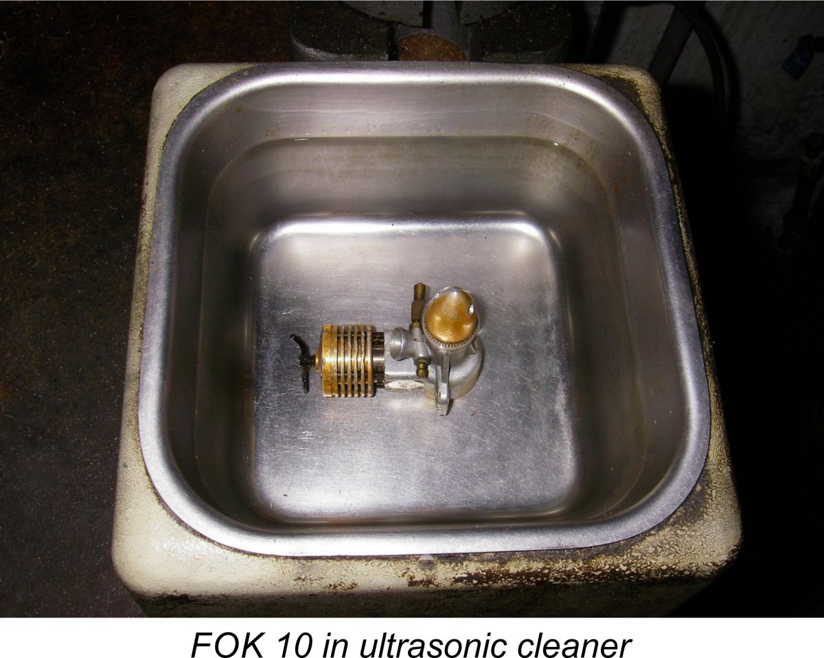 The first step is a thorough internal cleaning. Most model diesels from reputable manufacturers will be found to be fine in this respect, but there are a few brands which occasionally arrive with traces of shop debris inside. Even a used engine may have debris inside as a result of either improper storage or dirt ingestion during its last flight. My advice in all cases is to remove the backplate (using the correct tool(s), please!), immerse the engine in an ultra-sonic cleaner containing clean filtered solvent with the crankshaft vertical and positioned so that the induction port is open and then run the cleaner for a few minutes. Any debris should fall out of the rear of the crankcase onto the floor of the cleaner.
 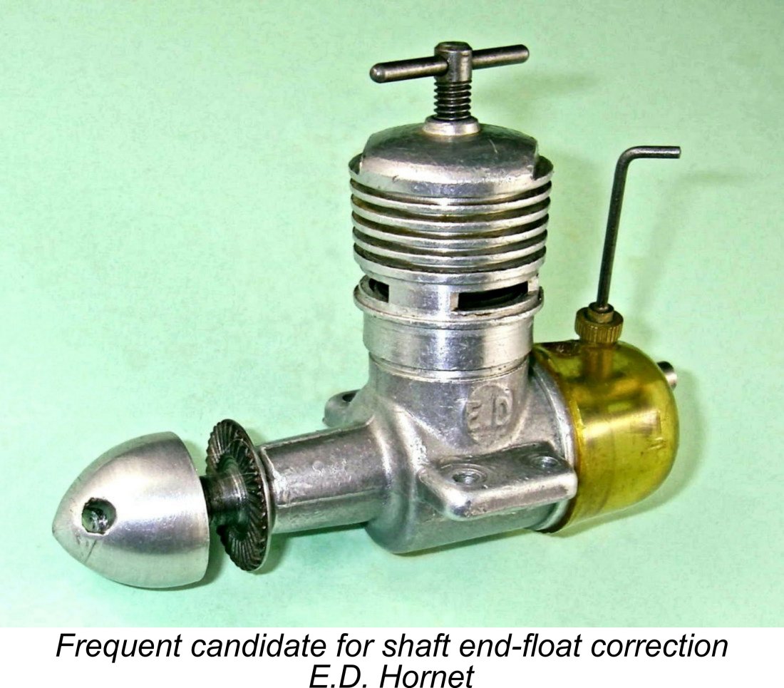 Although by no means combat powerplants, it's worth mentioning here that the very worst offenders in my experience were (and still are!) the old classic E.D. Bee and
 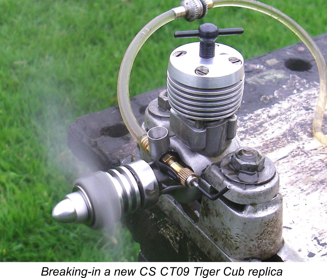 Most people would not view the break-in of a new model diesel as part of its maintenance schedule, but when we consider the amazing influence that a proper break-in can have upon engine life, there’s no doubt in my mind that it comes under the heading of advance maintenance. Nothing that you can do subsequently to maintain your engine can come close to matching the influence of a proper break-in upon engine life and performance. A proper break-in prior to a new engine seeing service in a model is an essential stage of the maintenance cycle. For full details of this critically-important issue, see my separate article on
 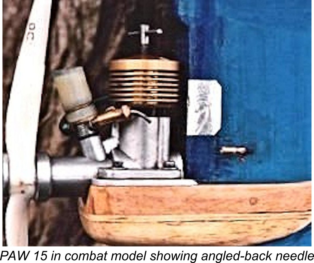 situations, such as sport, scale or stunt control line applications or free flight service, we’re all ready to fly at this point. However, if we’re using the engine in a really tough situation like vintage diesel combat, there are a few more things that we can do.
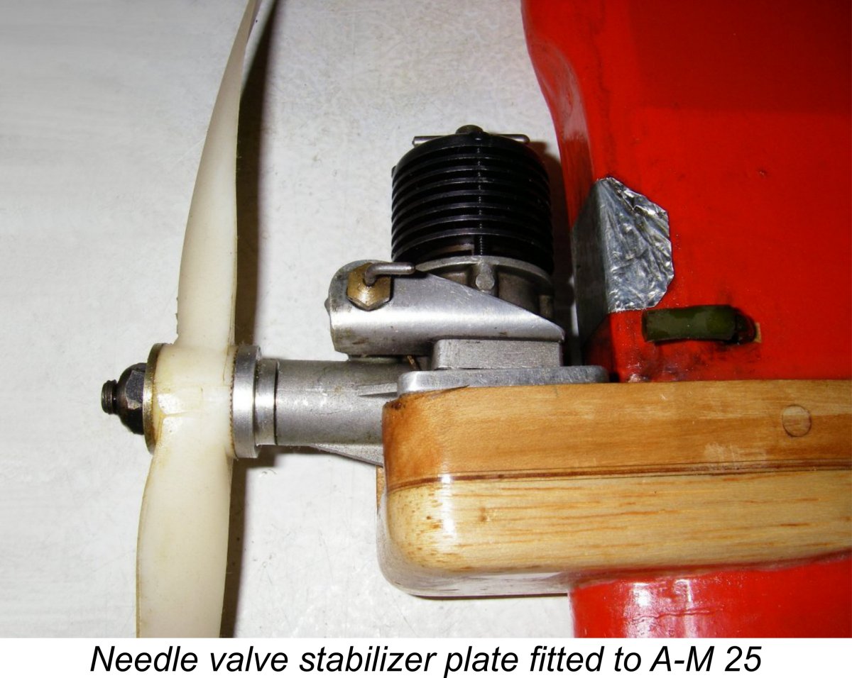 a plate is easily made from a small piece of light alloy sheet.
 OK, so we’re up and running! How’s the engine doing now that it’s in the air?? Well, running rich and/or undercompressed won’t do the engine any harm – they’re just something to be observed so as to allow an appropriate re-setting of the controls for the next flight. The important thing to watch out for is any sign of the engine running in an over-compressed or too-lean condition. This is made evident by a progressive “sagging” of the engine while it’s still running smoothly. It will begin to sound “harsh” and will often begin to throw out excessive exhaust smoke. In this state, it’s pre-igniting and placing its internal components under greatly increased stresses, as well as running far too hot.
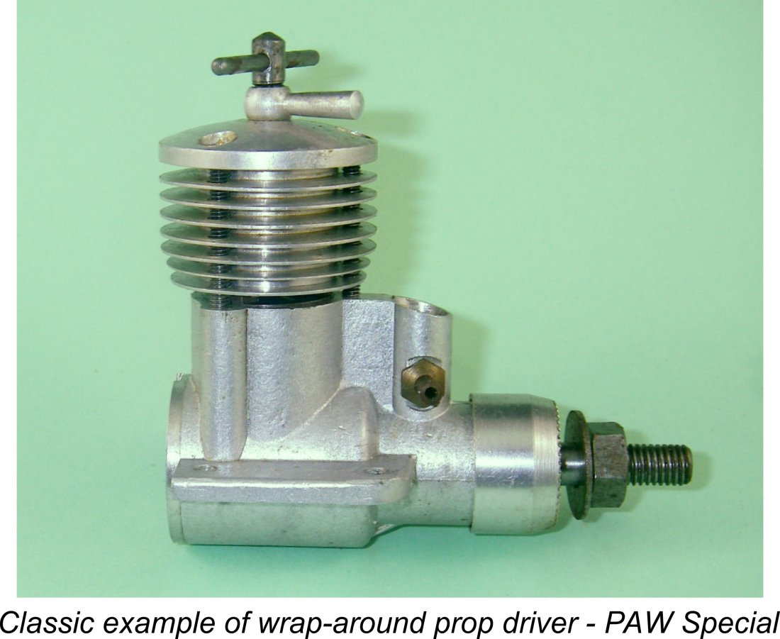 A "wrap-around" prop driver is very effective in minimising this tendency. This is a prop driver which is recessed at the rear to enclose the front of the main bearing housing. If you have a lathe and know how to use it, a stock P.A.W. or similar driver can easily be modified by recessing and re-tapering to enclose the front of the bearing while maintaining the correct end-float in the shaft (see above). Certain P.A.W. models come with wrap-around prop drivers as standard equipment, as did the
 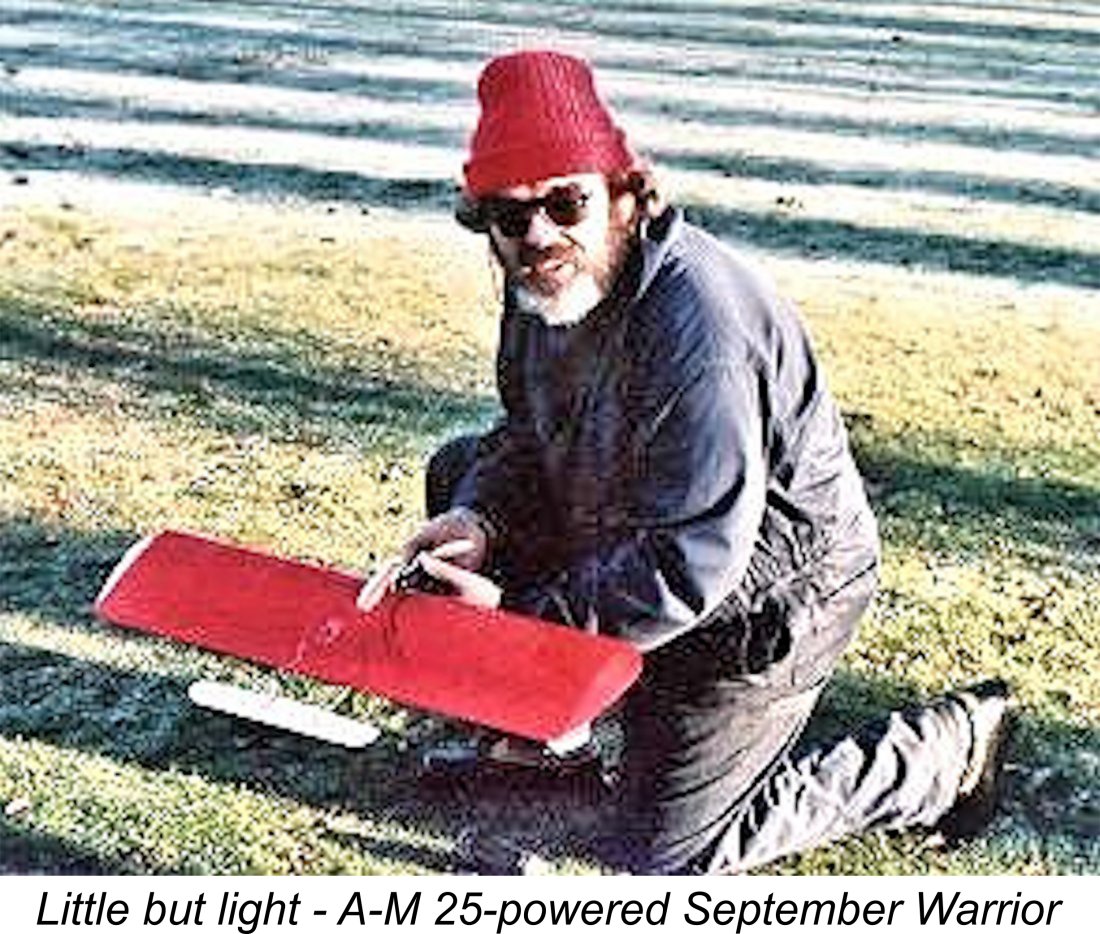 We had a 64 mph speed limit with streamer, which allowed one to use a smaller model with a less powerful engine and still be competitive. My own September Warrior with an
 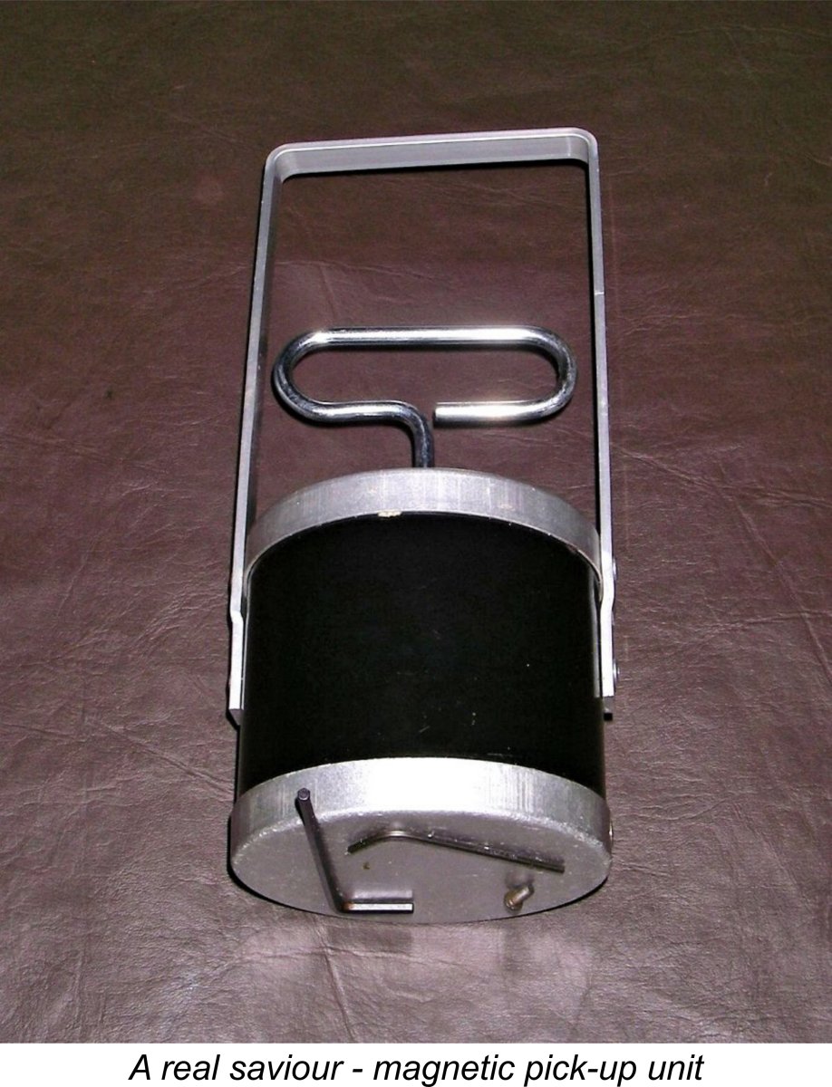 If you decide for any reason that you have to take the engine apart yourself (apart from the removal of the backplate, which is perfectly straightforward and is sometimes necessary for cleaning), there are a few things of which you should be mindful. First and foremost, do not tackle this work unless you have the right tools to do the job and are fully conversant with the correct approaching to the dismantling and rebuilding of miniature precision machinery.
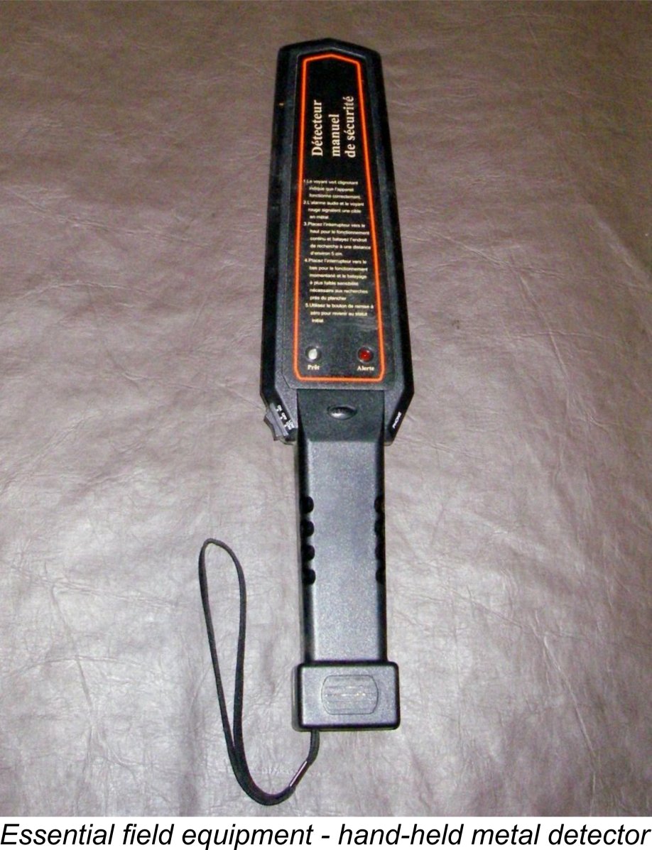 Next, the cylinder attachment screws should be removed, again using the correct tools for the fasteners involved. If the engine has a screw-on cooling jacket, please either use a strap-wrench or a very well-protected set of vice grips to avoid marring the external finish. Vice grips can be used (I often use them myself), but the key is to first set them so that they are a little too wide to grip the jacket without any filling. Once you have that setting, wrap the jacket with a uniformly sufficient thickness of some form of leather or fabric to created a fairly tight grip. This should remove the jacket, and there’s almost no chance of the grips coming into direct contact with the metal surface of the jacket since they’re set too wide to do so even if the fabric layer wasn't there. In cases when the jacket is excessively tight, a careful application of heat may help to expand the alloy relative to the cylinder and also soften any castor oil gum that may be causing problems.
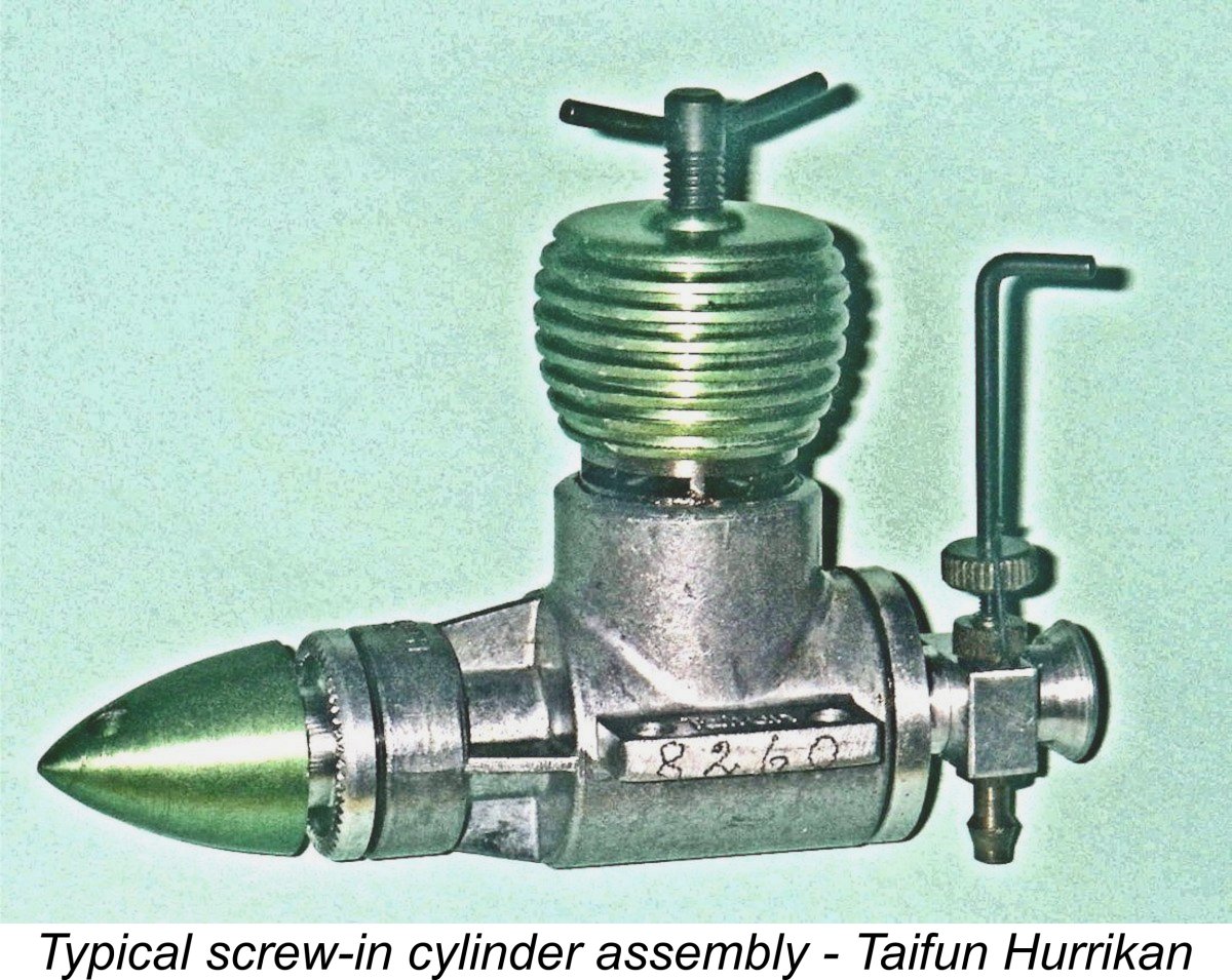 At this point, it's necessary to inject a strong word of caution in relation to engines having screw-in cylinders (like some of the Taipan, Taifun, Elfin and CS diesels, for example). There are no cylinder screws here - the cylinder must be removed by unscrewing, using the same tool(s) as for the screw-on cooling jacket. There's little point in marking the front of the cylinder with these models because the cylinder will choose its own orientation upon re-assembly! It will seldom align exactly the same, but there's no help for that.
 | |