
|
|
The E.R.E. 2.48 cc Diesel
Introduced in the latter part of 1946, the B.M.P. (standing for Bijou Model Products) 3.5 cc diesel was the product of a cooperative effort between Bournemouth resident Henri Baigent and a local precision engineering firm whose name is now lost. A short prototype series was produced in mid 1946, arousing great interest within the Bournemouth-area modelling community at a time when model diesel engines were still a great novelty in Britain. This encouraged Henri and his engineering partners to put the engine into limited production later in the year.
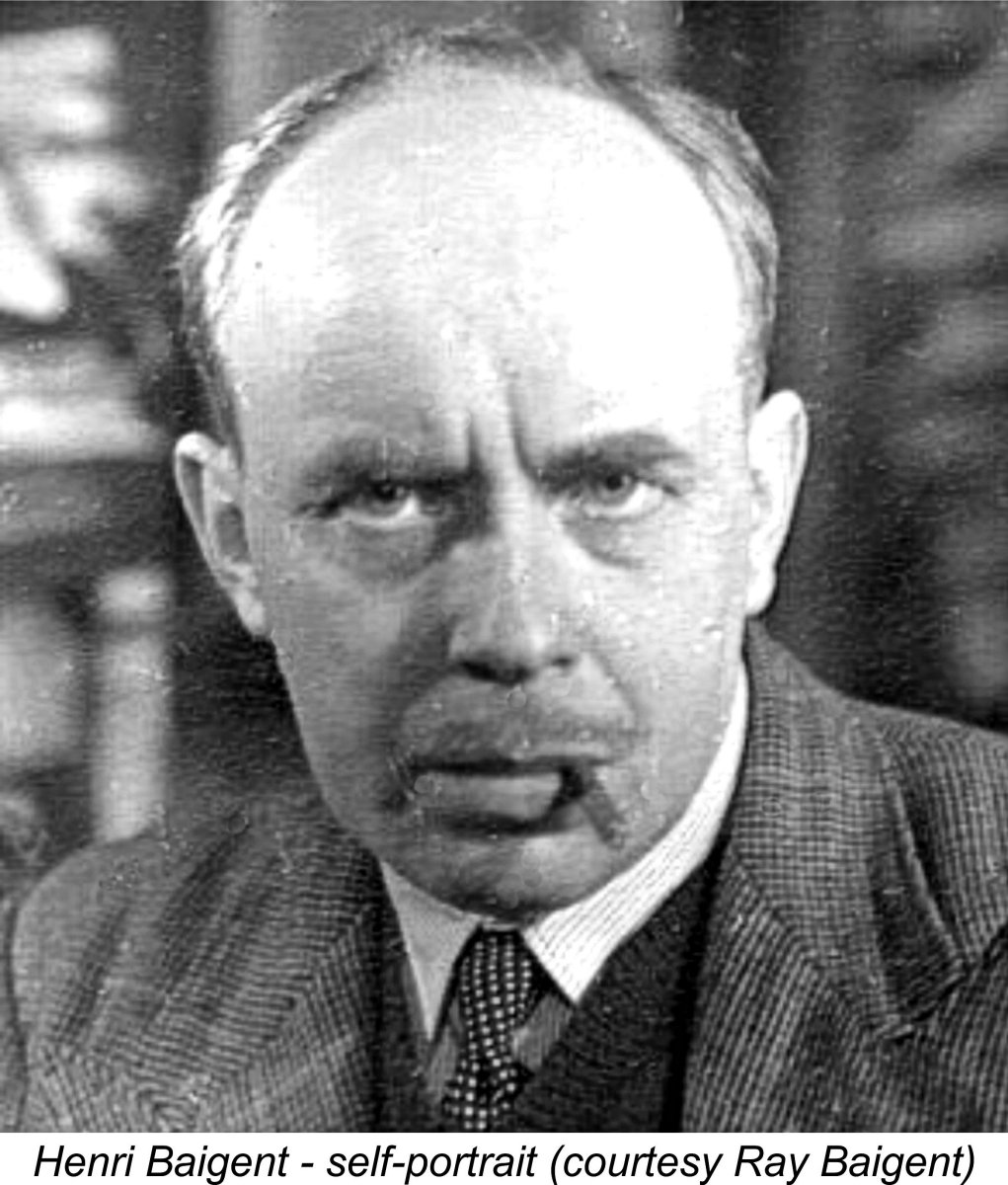
The manufacture of the B.M.P. engines was very much a hands-on affair as far as the 35 year old Henri Baigent was concerned. He was directly involved with all aspects of production, with his teenage son Ray Baigent helping out as opportunity offered during weekends and school holidays. All the casting work as well as the machining was carried out in-house.
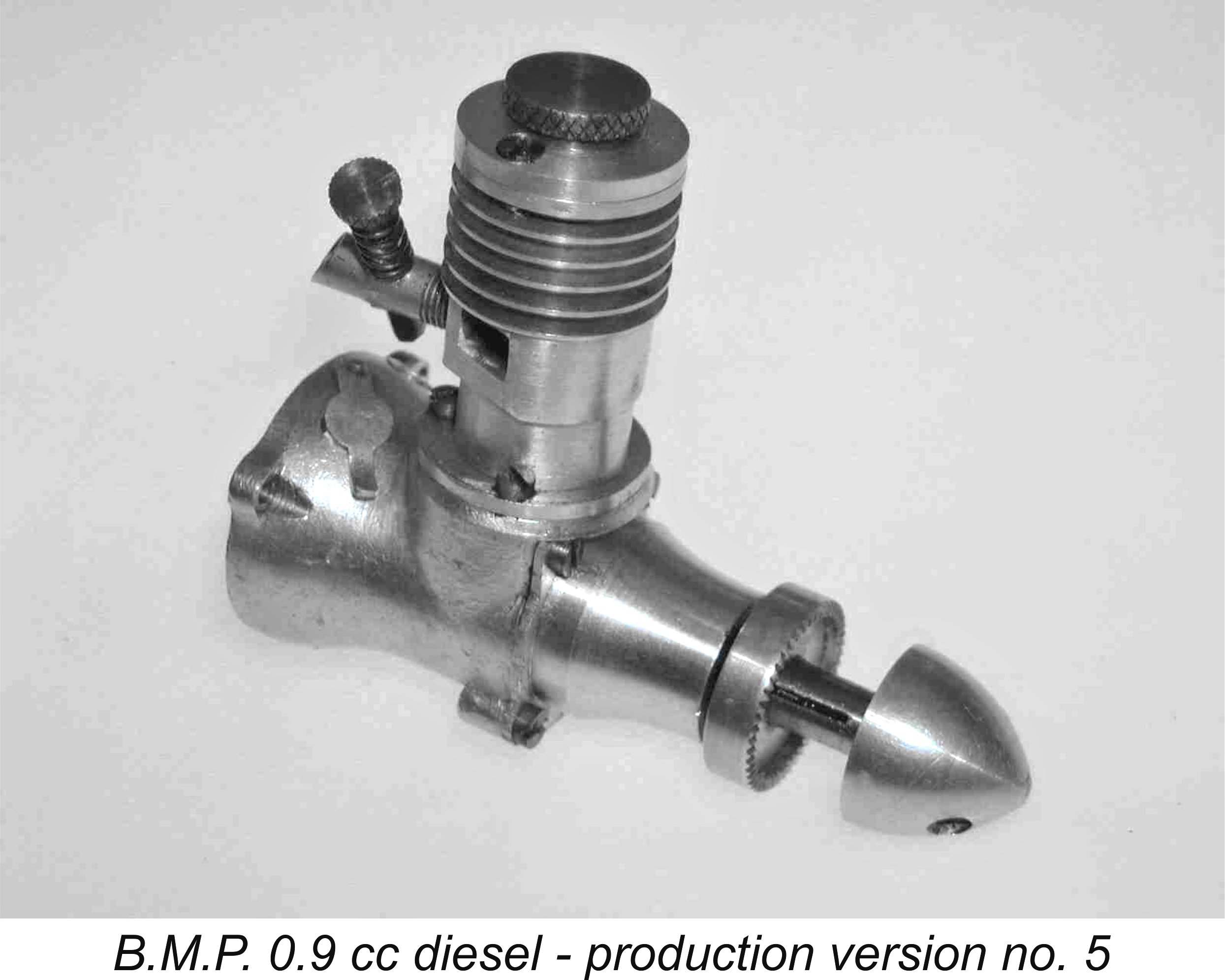
Following the winding-up of the B.M.P. venture, Henri Baigent continued to make model engines on his own account, now working from his own premises at 10 Beverly Gardens in Bournemouth. Ray Baigent continued to assist his father whenever possible. He recalled that a number of different one-off model diesels were made during this period, including one having a displacement of only 0.075 cc - However, the most tangible result of Henri’s ongoing model engine development work was the 1948 appearance of a now extremely elusive 2.48 cc crankshaft front rotary valve (FRV) diesel engine called the E.R.E. (English Racing Engine - a clear poke at the full-sized E.R.A. racing cars!). It is this engine which forms the central subject of the present article. It’s generally been my practise to write about engines or engine ranges of which I possess, or have direct access to, one or two examples to serve as review subjects based on personal hands-on experience. I’d held off writing in any detail about the E.R.E. because I didn’t have access to an example upon which to comment. Indeed, given the extreme rarity of these units, I honestly never expected to be able to cover this engine at all. All of that changed in 2022 when I was fortunate enough to be offered the opportunity to acquire a nice example of the E.R.E. 2.48 cc diesel. It wasn’t cheap, but I was buying knowledge as well as an engine, greatly enhancing its value in my eyes. My access to information relating to the E.R.E. was further improved by the fact that my good English mate Miles Patience also had a nice example which he was prepared to put through its paces on the test bench. As I saw it, my access to this level of information placed me under an obligation to share the engine to the extent possible. May as well get right to it! The E.R.E. 2.48 cc Diesel - a Capsule History
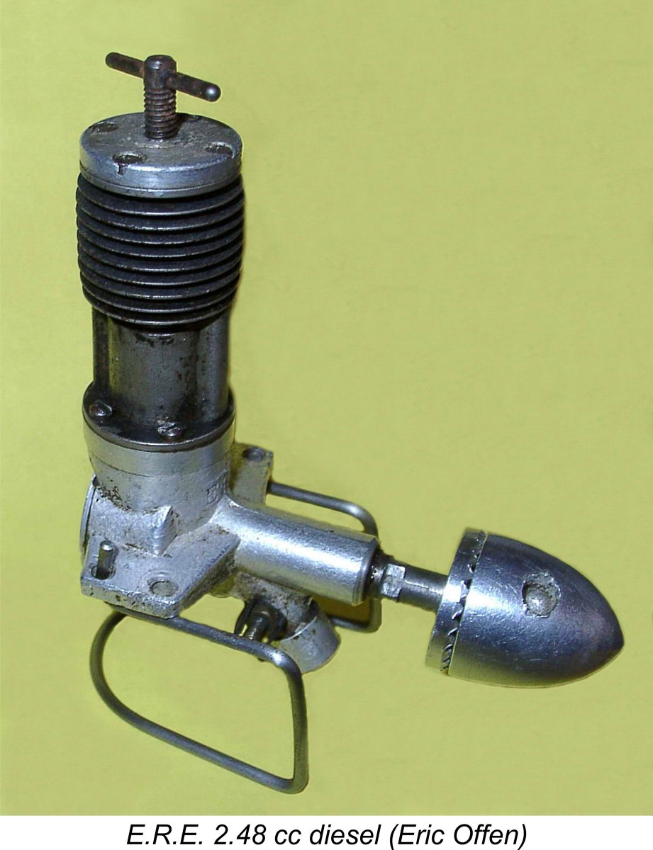
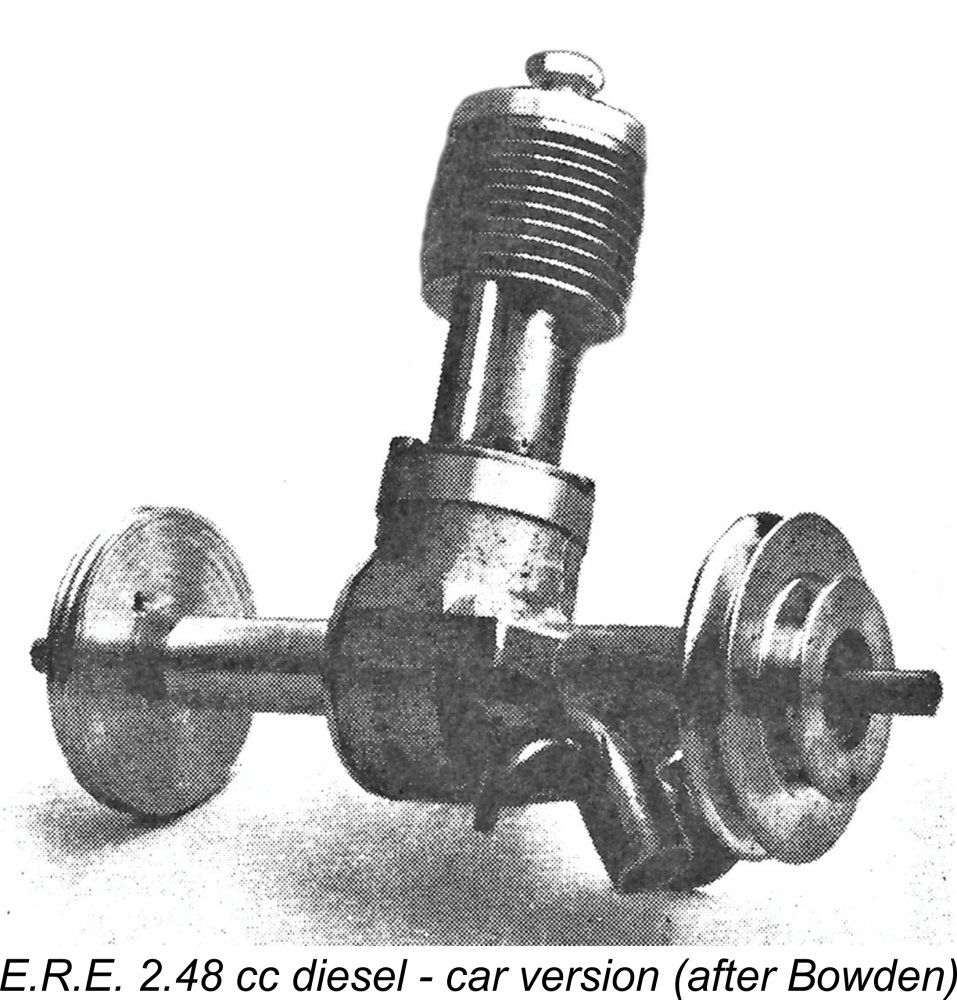
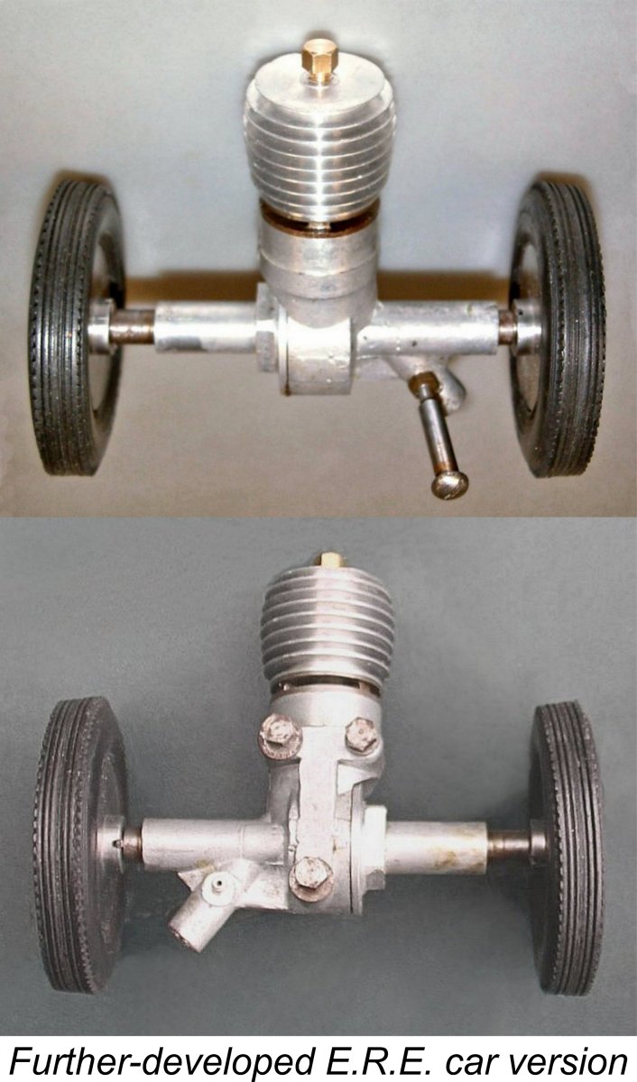
Although it was intended all along to be used competitively in both model aircraft and tethered car racing, the aero version of the engine seems to have come first. It was provided with a conventional prop driver and a nicely streamlined spinner nut, as seen in Eric Offen's image reproduced above. The original car version which soon followed was based directly upon the aero model, being essentially identical as far as the actual power unit went. It was equipped with a second subsidiary shaft and screw-in bearing which replaced the aero model's backplate. The subsidiary shaft was driven by the crankpin of the main shaft, creating a twin-shaft car powerplant. Both the main crankshaft and the subsidiary shaft were equipped with hubs to allow the installation of wheels having centrifugal clutches housed in My valued friend and colleague Hugh Blowers, who maintains the ever-informative Onthewire website devoted to tethered car and hydroplane racing, was able to carry the story of the E.R.E. car model still further. He provided photographic confirmation of the existence of a further-refined version of the E.R.E. car unit which was actually a completely different engine. The only component which this model shared with the original aero version was the crankshaft! The revised main casting omitted the beam mounting lugs in favour of a 3-point flat base mounting. The cylinder was now of the screw-in variety with 360 degree radial porting along with internal bypass passages. The cooling fins were machined onto the screw-on alloy cooling jacket now used. As far as I'm aware, no aero model was ever produced using this cylinder design. Hugh informed me that only a single example of this revised design is presently known to exist. Amazingly, it was still mounted in a car which had The Baigents took their testing work very seriously, to the point of creating a static thrust-measuring device to evaluate the various airscrew designs applied to their aero model. This took the form of a radially-pivoted arm mounted on ball-races with a spring load, which was calibrated using graduated pendulum weights. Very simple to make, it proved to be a great help in maximizing airborne performance.
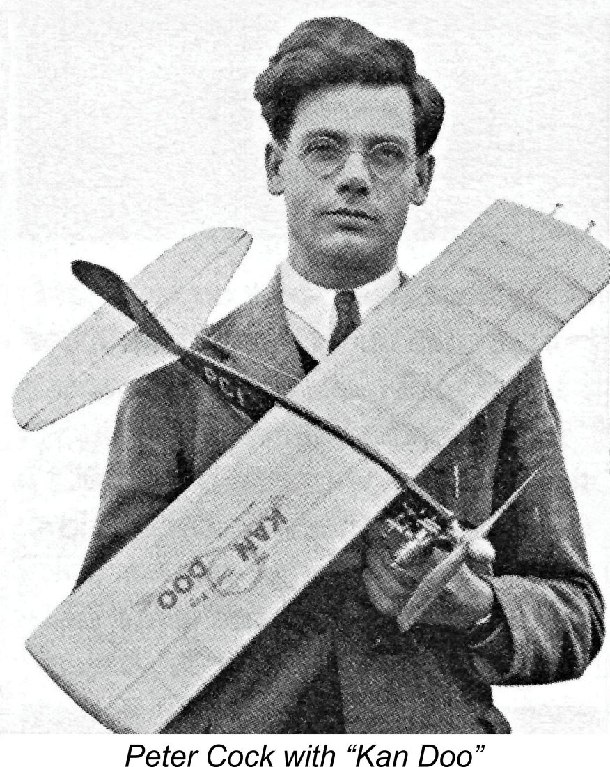
At the 1948 British Nationals, for example, the Baigents’ friend and Southampton retail agent Peter Cock won the control-line stunt Gold Trophy using a modified E.D. 2 cc engine in his "Kan Doo" design. It stands as a compliment to the qualities of the E.R.E. powerplant that for the 1949 event he switched over to the E.R.E., for which a stack of Ray Baigent’s own special ultra-thin propellers were prepared. The outer portions of the blades were so thin that they were semi-translucent, but of course they were easily damaged on landing. The props had to be mounted so that the engine would stop with the blades horizontal during the landing glide, since there was no undercarriage to land on - most competitors were then using a jettisonable trolley (aka dolly) for take-off in order to save weight.
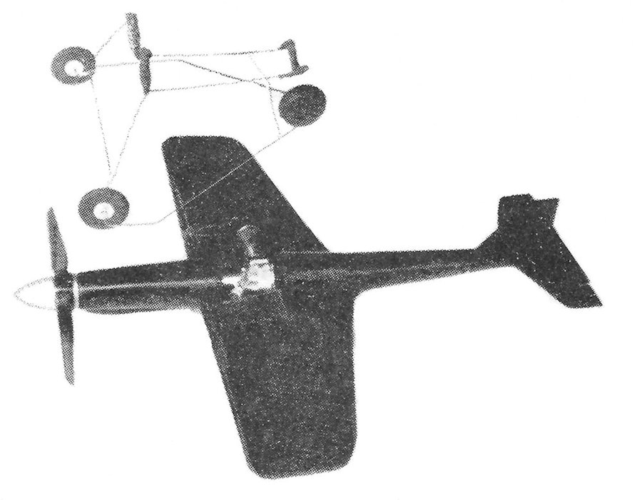
Henri Baigent made a very interesting control-line speed model for the E.R.E. engine. The accompanying illustration of this model seen at the left appeared in the third (and final) edition of Col. Bowden's previously-cited book "Diesel Model Engines". It shows that the E.R.E. engine was mounted amidships in the wing in a sidewinder configuration, while the prop was driven through a long drive shaft running forward from the engine. The drop-off dolly used for take-off is also shown in the picture.
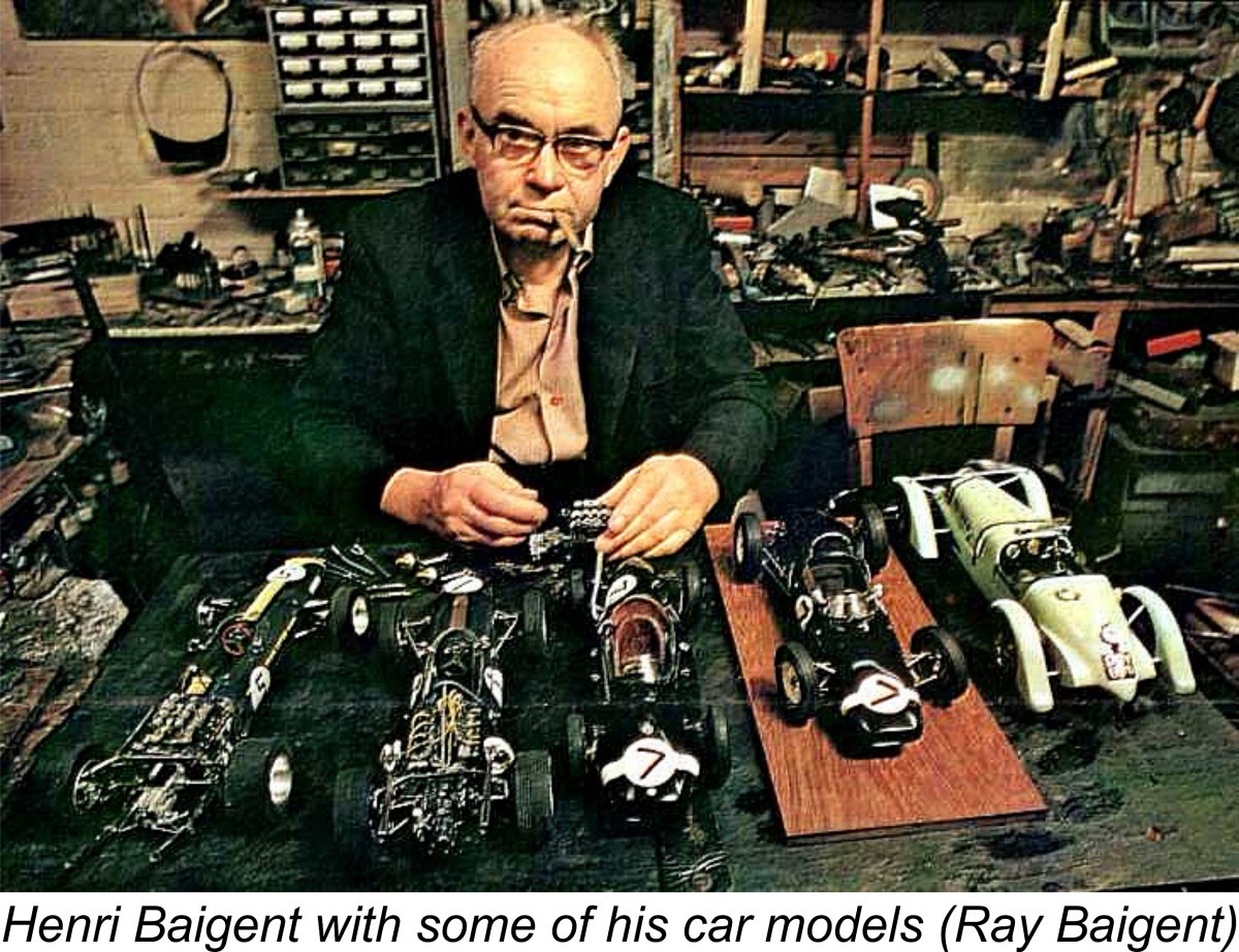
Unfortunately, Peter Cock's switch to the E.R.E. for 1949 coincided with the beginning of the period of dominance of the Yulon 30 glow-plug motor and the Elfin 1.8 and 249 radially-mounted diesels in the However, by this time Henri Baigent’s interests were well and truly focused upon the world of scale car modelling, leading him to abandon the model engine field in early 1949 after only a handful of E.R.E. 2.48 cc diesels had been produced. The engine is consequently very rare today. Its appearances at the 1949 British Nationals proved to be its last hurrah in an aeromodelling context. It is for his amazing subsequent achievements in relation to scale car modelling that Henri Baigent is best remembered today. But that’s another story that has been very ably told elsewhere by Henri’s son Ray Baigent, whose wonderful website on the life and work of his father is very well worth a visit. Henri Baigent died rather prematurely on April 13th, 1971 at the age of 62 years following a series of strokes. The modelling world had lost one of its genuine masters. The E.R.E.’s Advertising Record
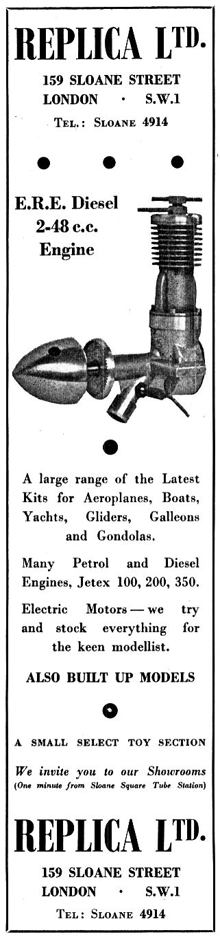
The first such appearance took the form of a placement in the Trade Section of the Classified Advertising feature in the September 1948 issue of “Aeromodeller” by Technical Models of 14 Palmerston Road in Southampton. This advertised the E.R.E. as being available from their shop at a price of £4 13s 0d (£4.65), characterizing it perhaps somewhat optimistically as “the hottest engine in its class”. Technical Models was owned by Baigent’s good friend Peter Cock, winner of the 1948 Gold Trophy and 1949 E.R.E. user, who was clearly trying to help out his friend by promoting the engine. The next appearance of the E.R.E. in the advertising record took the form of its inclusion in an advertisement placed by Replica Ltd. of 159 Sloane Street in London in the 1949 “Model Planes Annual” published by Ian Allan. Since this publication was first promoted in the January 1949 issue of “Aeromodeller”, this advertisement (seen at the right) must date from late 1948. At this time, Replica Ltd. were a regular advertiser in “Aeromodeller”, but none of their adverts in that magazine mentioned the E.R.E. The Replica Ltd. advert in “Model Planes Annual 1949” was a one-off, featuring a prominent image of the E.R.E. but including no price or other details. This leaves us wondering if they actually stocked the engine or were just making a cast to see who bit! They were quite likely trying to determine whether or not the engine was worth stocking! Most interestingly, the Trade Section of the Classified Advertisement feature in both the February and March 1949 issues of “Aeromodeller” included advertisements from Baigent himself, offering the E.R.E. for sale from his home address in Southampton at an unchanged price of £4 13s 0d (£4.65). The placement for February 1949 wrongly listed the engine as the “E.D.” 2.5 cc diesel – clearly a compositor’s error. Perhaps Baigent got the March 1949 advert free to compensate him for the oversight! Regardless, that March 1949 listing by Baigent himself was the E.R.E.’s final advertising appearance. The E.R.E. 2.48 cc Diesel - Description
This being the case, I’m on my own ...... well, almost! All I have to go on is an examination of a couple of actual examples of the aero model plus a few test figures from myself and my greatly-valued English friend Miles Patience. Even this is qualified by my reluctance to dismantle my own "experienced" and hence seemingly well-settled engine beyond the removal of the cylinder and head. With these limitations on my access to information in mind, let’s get down to business!
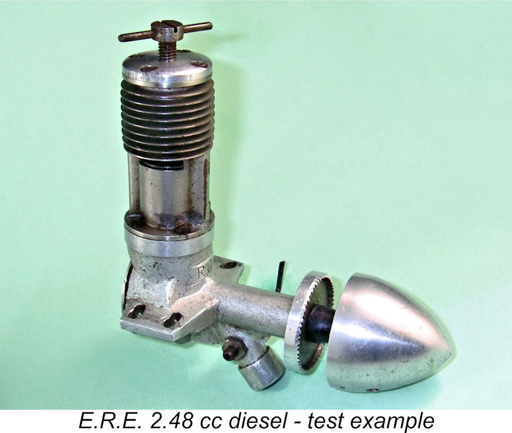
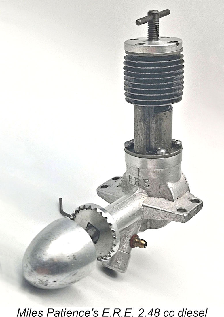
As one might expect from looking at it, the E.R.E. was a long-stroke design. Checked bore and stroke were 13.8 mm (0.545 in.) and 16.6 mm (0.653 in.) respectively for a stroke/bore ratio of 1.20 to 1 and a displacement of 2.48 cc (0.151 cuin.). The complete engine weighed in at 157 gm (5.54 ounces). This latter figure may seem rather high for a simple plain bearing 2.5 cc engine like this one, but the unusually large and mostly solid spinner contributes a healthy 31 gm (1.09 ounces) to the The engine was built up around a sand-cast crankcase which incorporated the main bearing housing, updraft intake tube and beam mounting lugs in unit. The engine's ERE name was neatly stamped onto the upper front surface of the crankcase, but no other markings were applied. In particular, none of the engines appear to have borne serial numbers.
The cylinder was provided with two generously-dimensioned opposing exhaust ports of rectangular shape. Two far more modestly-sized opposing transfer ports of rectangular shape were located between them, resulting in a very similar configuration to the later Cox engines (although the arrangement had been used previously by others). The transfer ports overlapped the exhaust ports to a considerable extent, and their overlap was increased through the provision of two shallow chamfers in the circumference of the piston crown fore and aft at the bypass locations. They were supplied The crown of the cast iron piston featured the two shallow transfer chamfers mentioned earlier. One of them is visible in profile in the image at the right. The piston drove the crankshaft through a very long conrod machined from light alloy. The crankdisc with which this rod interacted was quite heavily counterbalanced through the removal of sizeable scallops of material from either side of the crankpin. I was able to confirm these details simply by removing the cylinder.
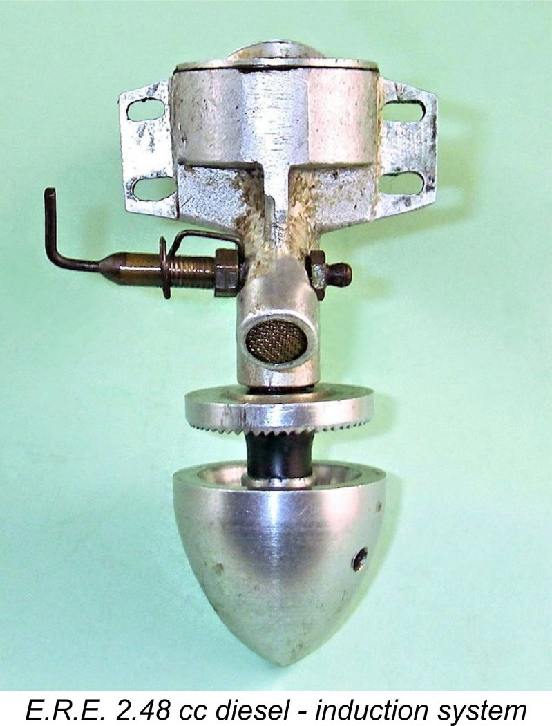
The induction arrangements were of some interest. I mentioned the distinctively-angled updraft intake earlier. The induction tube was capped with a pressed-on light alloy open-ended sleeve having a narrow internal step which trapped a piece of metal gauze at the point of entry, doubtless to serve as a form of air filter. This was likely motivated by the engine's intended use as a car powerplant, where the ingestion of kicked-up dirt is to be expected. The needle valve was a basically conventional transverse spraybar type. Its main The engine was completed by a screw-in backplate which was provided with two holes to permit the use of a pin spanner for tightening. My example has a strange little radially-oriented 8BA screw positioned near the rear of the crankcase above the left-hand mounting lug. This can be seen in a number of the accompanying images. The function of this screw is unclear - it may or may not interact somehow with the backplate. It was my uncertainty regarding the function of this screw which dissuaded me from disturbing it or removing the backplate to allow complete disassembly of the engine. That's about all that I can tell you about how the E.R.E. goes together. Next question - how does it run? Let's find out! The E.R.E. 2.48 cc Diesel on Test
My example has clearly been quite well used in the past - the carbon residues on the piston crown and in the combustion chamber attest to that! This in itself implies that the engine had merit as an operational powerplant - it's the good 'uns that get the use! It bears a number of other clear signs of this previous use, including the regrettable fact that the holes in its mounting lugs have been laterally elongated, presumably to permit the adjustment of the engine’s thrust line in a model or to fit a mounting created for a different engine. It does however retain its original spinner and needle valve, both of which were missing from Miles's unit as received. It remains in fine mechanical condition, with almost no detectable slop in the bearings and an excellent compression seal. To put it quite bluntly, the oversized prop driver and spinner nut were a total pain from a testing standpoint! I have no idea what size of airscrew was envisioned by the maker, but the diameter of the driver's toothed rim is far greater than the hub diameter of any of my usual APC and Taipan test props. I found an old wooden 14x6 that I had lying around doing nothing, trimming it down to a very wide-blade 9x6 just for the initial runs and the running photos. For the actual testing, I stayed with hefty wood props which had relatively large hub diameters. Fortunately, I had a set of such props which I had calibrated by comparing them on the test bench with APC and Taipan items having known characteristics.
One obvious way to get around this issue would be to set the needle at what seemed to be a relatively rich setting (using a static air test as my guide) and then install a remote needle valve in the fuel line. This would restore happiness by making the mixture fully adjustable. Of course, this wouldn't be an issue with the engine mounted in a model, so it can't be viewed as a criticism - just an idiosyncracy that has to be taken into account when testing the E.R.E..
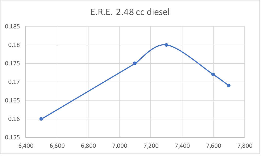
Given the E.R.E.'s probable long period on the shelf in various collections, I elected to give the engine a few shake-down runs using my specially-created large-hub 9x6 wood prop before commencing the actual test. Before mounting the engine in the stand, I set the needle using the old standby blow test using an empty fuel bulb. I positioned the control arm so that it was up against the test stand in what I judged by the detectable "hiss" to be a slightly rich position. This gave me around a 3/4 turn range on the leaner side over which the needle could be set before coming into contact with the stand once more. Depending on how things went, I had a remote needle valve available to insert into the fuel line. One idiosyncracy of the E.R.E. is one that it shares with other engines featuring updraft intakes when mounted in an upright orientation - finger choking accomplishes very little, because any fuel drawn into the venturi simply drips straight out of the intake without getting into the engine. In any event, the sharp forward angle of the intake places the opening very close to the prop, making finger choking extremely inconvenient. It was clear that priming through the exhaust would be the way to go. This impression was amply confirmed by experience. With practise, I was able to fill the fuel line using the limited amount of finger choking which was possible. That having been done, a small exhaust prime immediately got the engine firing, with a start following within a few more flicks. Equally conveniently, the cut-down wide-blade 9x6 prop that I had created especially for the initial runs proved to be perfectly matched to the E.R.E.'s power curves. The engine turned that prop at 7,100 RPM, only a few hundred RPM shy of what turned out to be the peak. The E.R.E. proved to be an unfailingly good starter provided an exhaust prime was administered as a preliminary. It was also very responsive to both controls, making it a real pleasure to test. Running was smooth and steady at all speeds tested, with no tendency to sag once well warmed up. Vibration levels too were well within acceptable limits. The following data were recorded.
All of the above airscrews were large-hub wood items. The power absorption coefficients that I have for them are probably a little less certain than those for my APC and Taipan props, but they appear to be fairly mutually consistent, hence being unlikely to be far off base. Regardless, the figures suggest a peak output of some 0.180 BHP @ 7,300 RPM. While this may not seem like a true "racing" performance, we have to remember that this was 1948! The peak output is considerably higher than the 0.128 BHP @ 7,800 RPM reported by Lawrence Sparey in his "Aeromodeller" test of the E.D. Mk. III published in the magazine's April 1949 issue. The E.R.E. clearly out-torques the E.D. by a considerable margin. Its appreciably longer stroke doubtless contributes to this characteristic. In fact, the unmodified E.R.E.'s peak output is only a little short of that achieved by my own tuned example of the E.D. Mk. III, which developed 0.194 BHP but had to rev to 9,800 RPM to get there. Once again, the E.R.E. clearly wins hands down in the torque department. Even with its tank removed, the tuned E.D. slightly outweighs the 157 gm E.R.E., turning the scale at 168 gm. The power to weight ratios of the two engines are thus very close indeed. In practical terms, the E.R.E. could undoubtedly give even a competently tuned E.D. Mk. III a good run for its money!
As mentioned earlier, my valued mate Miles Patience was happy to extract a few test figures from his own very nice example of the E.R.E., which started and ran just as well as my unit. He tried it on APC 10x6 and 10x4 props, for which I had credible power absorption coefficients. His engine turned the APC 10x6 at 7,100 RPM (around 0.132 BHP) and spun the 10x4 at 7,900 RPM (approximately 0.139 BHP). The implied power outputs at these speeds are well down on those reported at the same speeds for my own example. This could be down to differences in the two engines' levels of "experience", or they could result from the fact that Miles' example was missing the original needle valve assembly, forcing him to use a non-standard replacement which may or may not provide an equivalent choke area. Finally, it's possible that my example has been subject to some level of "tweaking" which my inability to dismantle it fully prevented me from discovering. That said, the differences are of no consequence. Both Miles' engine and my own example performed at levels which would have made them completely satisfactory engines to use as of 1948. Conclusion
The fact that after 1949 Baigent took no further interest in model I/C engines must be seen as a loss to the aeromodelling world. If he had done so, we would doubtless have seen more fine examples of his talents both as a designer and constructor of such units. However, we would not then have seen the truly outstanding scale model cars which he produced during subsequent years. Aeromodelling's loss was very much car modelling's gain. The E.R.E. 2.48 cc diesel is a worthy reflection of Henri Baigent's capabilities as a model engineer. The engine is mega-rare today - Miles Patience and I were extremely lucky to acquire our examples. Probably no more than 20 or 30 examples were produced in total. Still, there are probably a few more unreported units out there - keep your eyes peeled!! _________________________ Article © Adrian C. Duncan, Coquitlam, British Columbia, Canada First published September 2024 |
||
 In an earlier article to be found on the late Ron Chernich’s
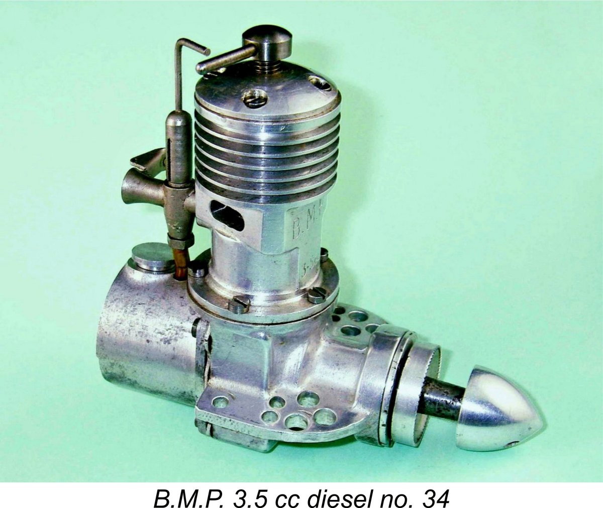
 dummy brake drums. According to Col. C. E. Bowden writing in his book "
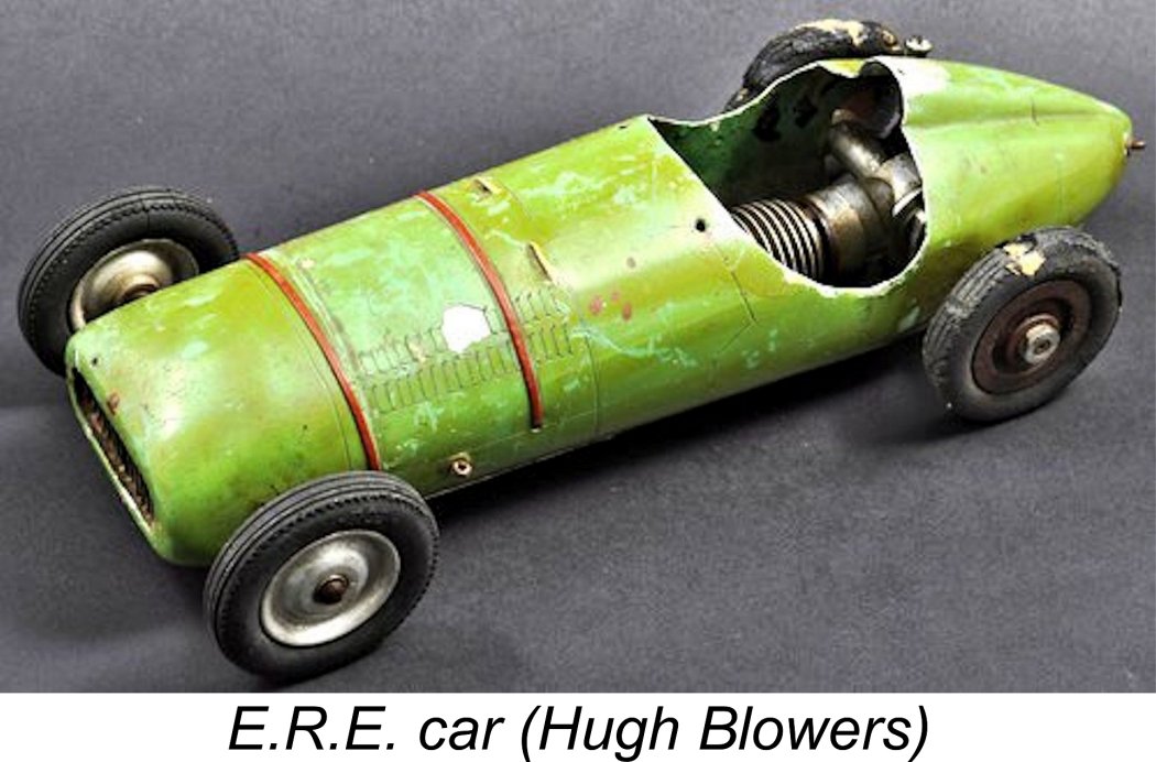
 Of course, such ultra-thin props were also ill-adapted to withstanding the stresses imposed by hand starting. For this reason, the Baigents advocated the use of an electric motor with a rubber cup to grip the spinner when starting the aero version.
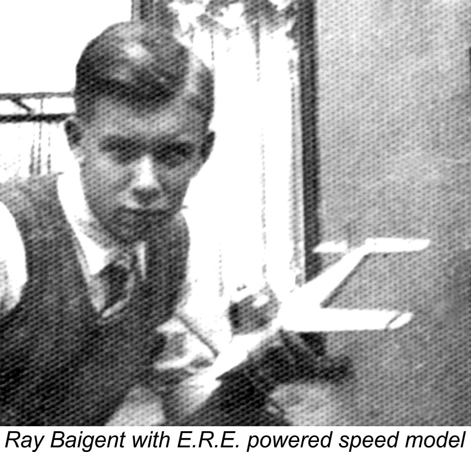
 Baigent seems to have had at least some level of commercial ambition for the E.R.E., because the engine did make a few advertising appearances, which my valued friend and colleague Gordon Beeby was kind enough to sort out for me.
 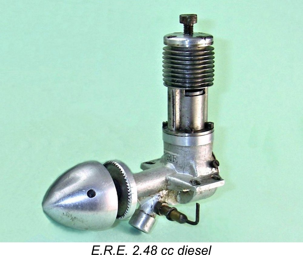 The E.R.E. 2.48 cc diesel was never the subject of a published test report in the modelling media of the day. Its sole contemporary appearance in print of which I’m aware was a single brief paragraph in the third edition of Col. C. E. Bowden’s book “
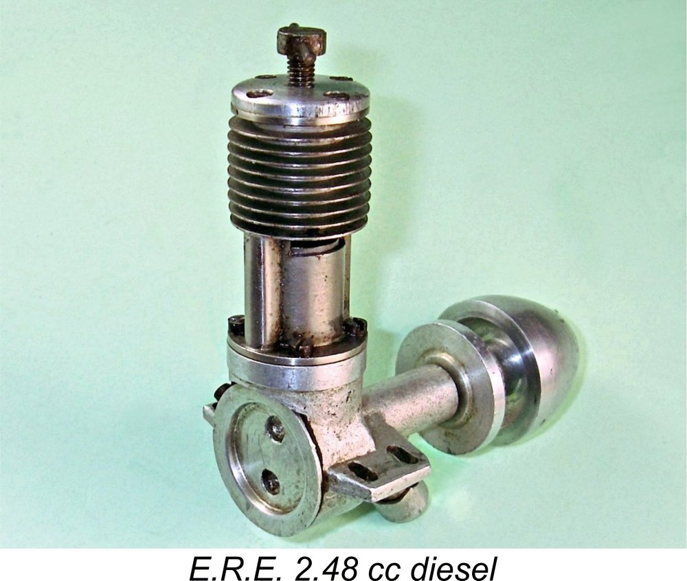
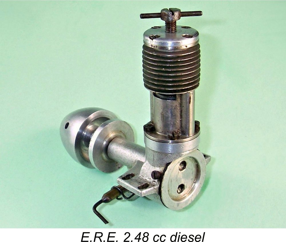 The E.R.E. 2.48 cc diesel was a basically conventional plain bearing crankshaft front rotary valve (FVR) diesel of its day. It was distinguished both by its forward-angled updraft induction system and its unusually tall "skinny" cylinder, both of which combined to give it a rather distinctive appearance. The aero version’s oversized spinner nut and prop driver also made their own contributions to the engine’s unusual appearance.
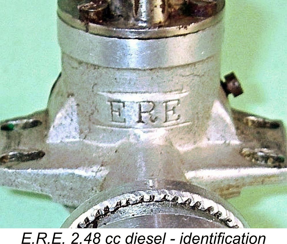 total. Without the heavy spinner, the basic engine turns the scales at a quite commendable 126 gm (4.44 ounces). I’m sure that a lot of aero users would have replaced the spinner with a nut-and-washer combination.
 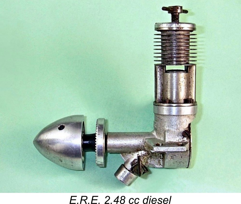 Starting at the top, the engine featured a bolt-on cylinder which was turned from a steel billet with integral cooling fins. A cast iron contra-piston was employed. The comp screw of the aero version was a conventional T-shaped component featuring a steel tommy bar which was inserted transversely through a slot-head steel "button". The car versions evidently omitted the tommy bar, relying instead upon the steel “button” alone, with its transverse slot being used for purchase. Such a compression screw had also been used on some examples of the
 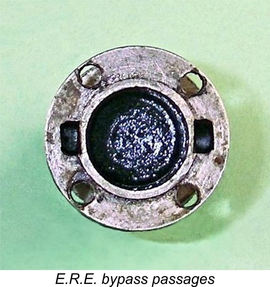 Moving on down, the cylinder was secured to the crankcase with four 6BA machine screws. A thin paper gasket was used to ensure a good seal.
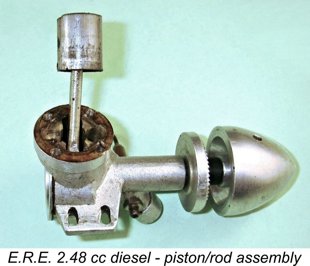
 Unusually for such a rare engine, I actually have access to test data from two different examples of the E.R.E. One is my own aero example, while the other is the similar unit owned by my good English mate Miles Patience. Miles very kindly agreed to put his engine through its paces on the test bench to complement my own testing.
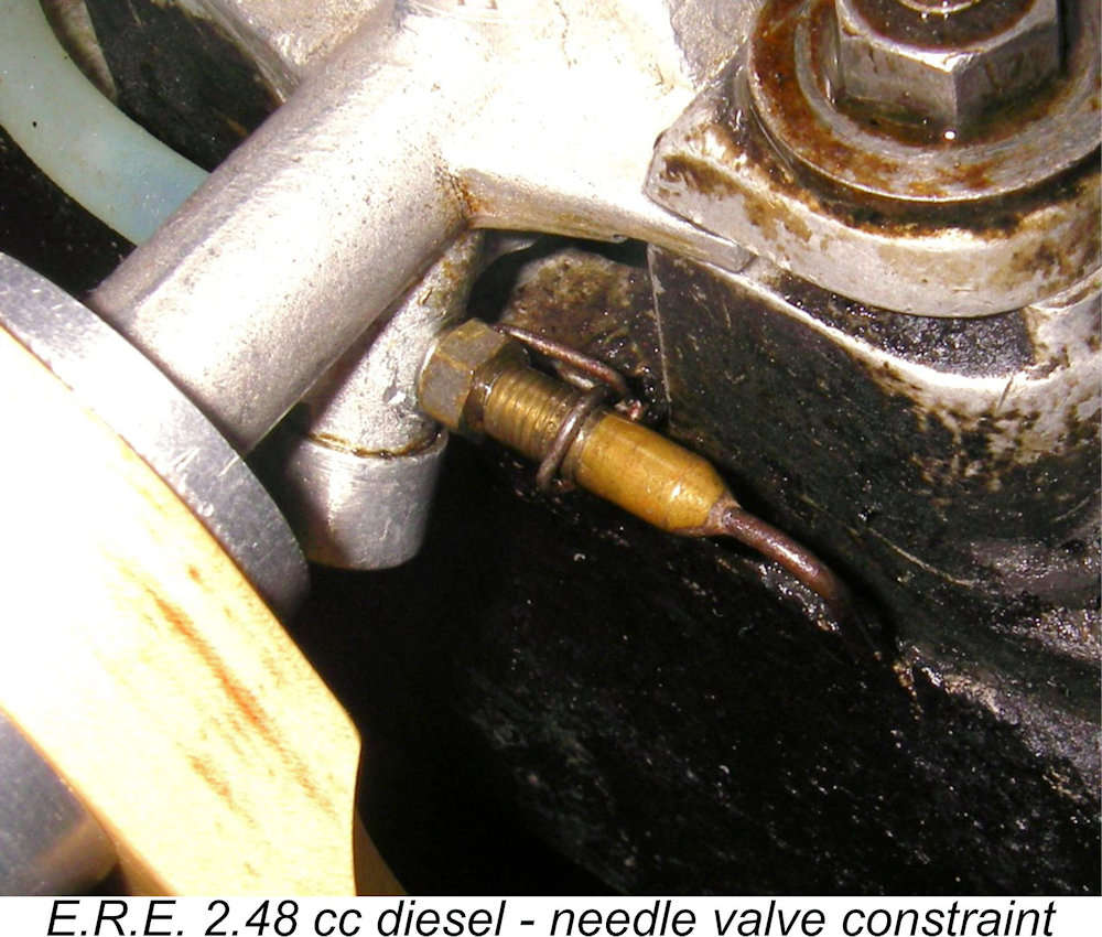 Even then my troubles weren't over! The location of the spraybar places it immediately forward of the test stand below the mounting lugs. It turned out that the needle couldn't be rotated through the full 360 degrees without the right-angled "handle" portion fouling the test stand. This meant that I was confined to an approximately 270 degree angle of rotation of the needle. If the engine needed me to make adjustments beyond this limit, I would actually have to loosen it in the test stand to position the needle in the "next" 270 degree rotational zone. Even then, access to the control to make adjustments was greatly compromised. Another total pain in the neck!
 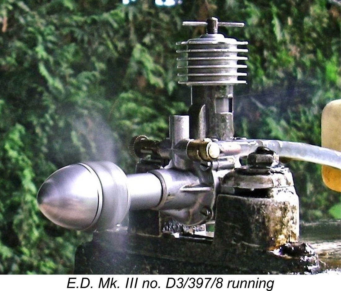 As my regular readers know, I always like to include a comparison of a given test subject with its contemporary opposition. In this instance, I thought that the 2.46 cc
 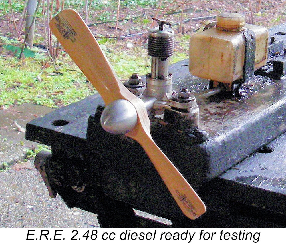 With the needle set in this way, I mounted the E.R.E. in the test stand.
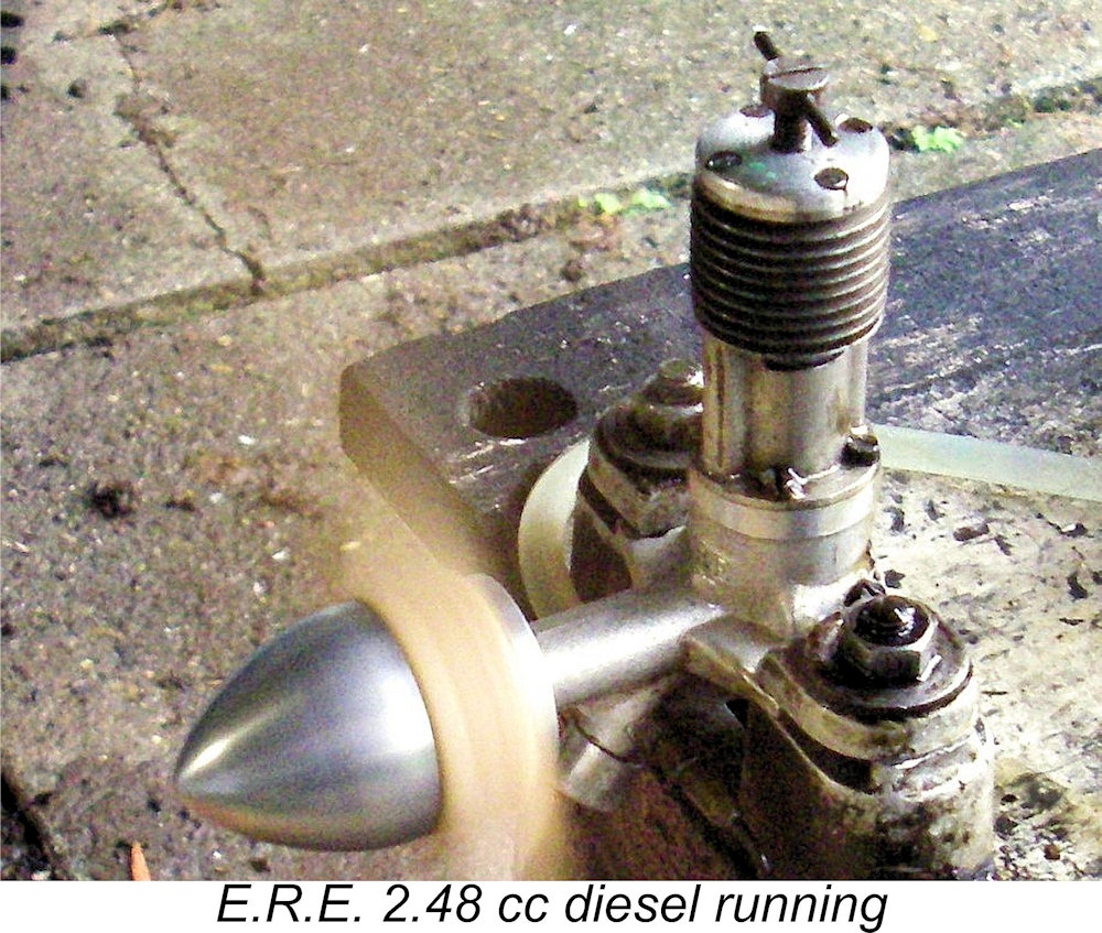
 Overall, I was very impressed with the E.R.E. on the basis of this test. It came through the session with flying colours, displaying no evidence of stress at any time. It showed itself to be a sturdy, well-made and user-friendly model diesel with an excellent performance by the standards of its day.
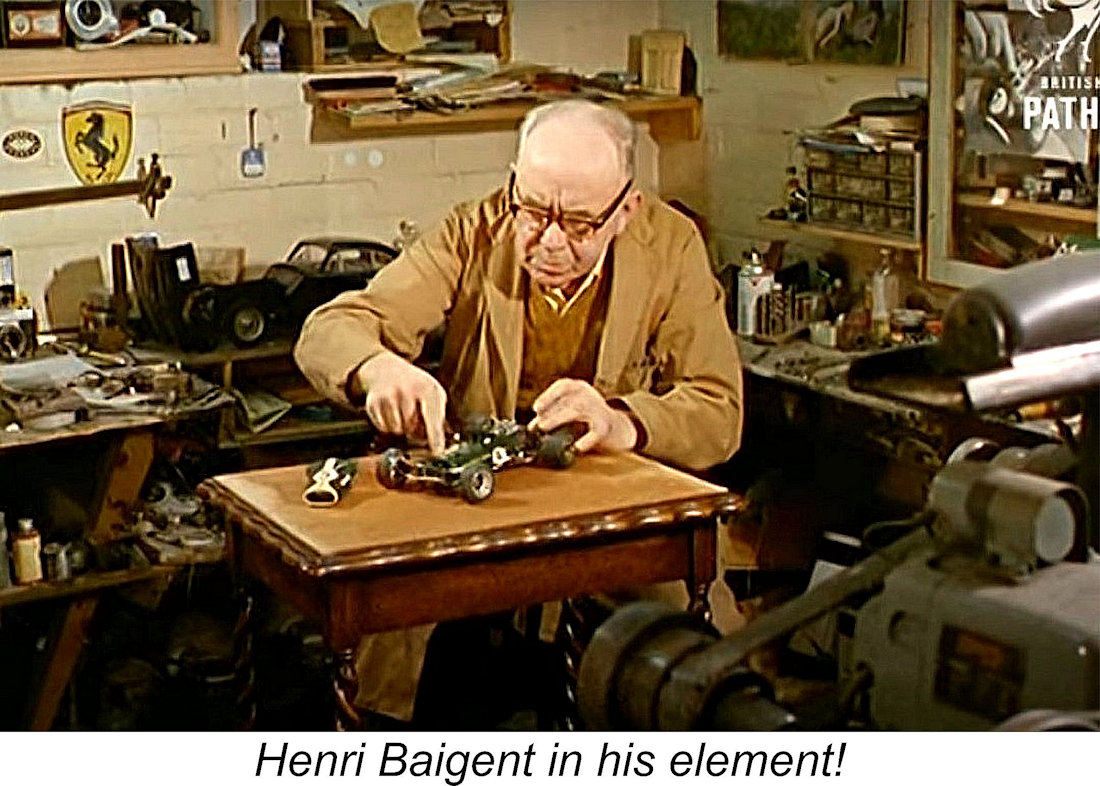 Reading the history of Henri Baigent's involvement with modelling, it's apparent that his early post-WW2 involvement with model diesels was most likely prompted by his son Ray's interest in aeromodelling coupled with his own interest in model engineering. He used the three-year period of his involvement to produced a number of engines having considerable merit by the standards of their day.
 | |