
|
|
Prop Selection for Classic Control-line Models
However, model speed is important in other categories as well. This is because model speeds determine lap times on a given line length, a factor which may be important in terms of the maintenance of adequate line tension or selection of an appropriate line length for pilot comfort. This being the case, it’s useful to have some basis for predicting and then checking the potential airspeed of a given model/motor/prop combination.
The calculation begins with the pitch of the airscrew. This is the distance which the airscrew would move ahead through the air in a single revolution if it functioned as a machine screw with no slippage, i.e., if air were a substance with no “give” in it. The accompanying diagram extracted from "Model Aero Engine Encyclopaedia" illustrates the concept. In reality of course, air is a fluid having a very low viscosity. Consequently, a degree of slippage is bound to occur. The more efficient the prop, the lower the slippage, but a certain degree of slippage is inevitable even with the most efficient props. Our formula assumes that there will be around a 20% slippage factor, a figure which generally yields results which are quite close to what we observe in the field for most props above 7 inches in diameter operating in the typical "classic" rpm range. Generally speaking, slippage rates increase as prop diameter and blade area decrease or model drag increases, but the 20% assumption seems to work well enough for estimation purposes with props down to around 8 inch diameter or a little less. Having adopted a credible slippage factor, it’s then simply a matter of calculating how far the prop will theoretically move forward in a given time interval at the anticipated turning rate in flight. If we multiply the pitch by the anticipated rpm and take off 20% to allow for slippage, we’ll get the distance theoretically travelled in one minute. Multiply this by 60, and we have the speed as a distance per hour. By using the appropriate conversion factors, this is easily expressed in mph or km/hr, depending on one’s preference. I won’t bore you with all the conversion factors involved in making sense out of all this! Suffice it to say that if (like me) you’re one of those old die-hard stick-in-the-muds who still tends to think of pitches in inches and speeds in miles per hour, then the formula that works for you is as follows: Airspeed (mph) = [RPM x Pitch (inches)] ÷ 1320 The equivalent formula in metric units is easily worked out using applicable conversion factors. Or simply multiply the result by 1.61 to convert mph to km/hr.
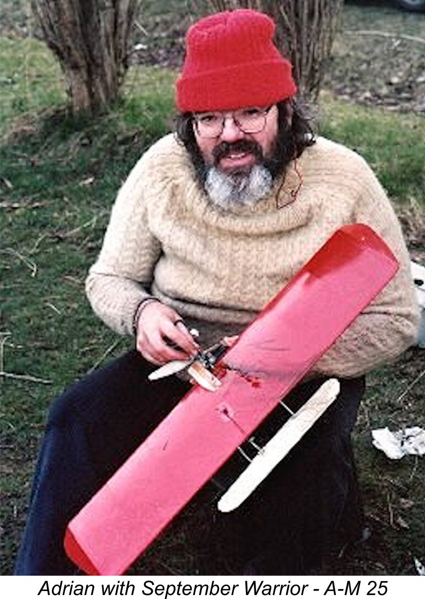
As an example, let’s assume that we wish to fly a relatively slippery vintage combat model such as the illustrated September Warrior powered by a classic 2.5 cc diesel - in this case, a tuned A-M 25. In this case, the requirements of competition suggest that the highest possible airspeed is desirable, along with good acceleration out of the turns. Naturally, we’d like to select the best prop for the job, and we’d like to know how fast we can expect our model to go on that prop. We’ll assume that our engine is known from available test results to peak at around 14,000 rpm, so for best in-flight performance we want to take advantage of its maximum output by having it running in the air at somewhere near that speed. If we assume something like a 20% increase in engine speed between ground and in-flight speeds, this suggests that we should prop the engine for around 11,500 rpm on the ground. So the trick becomes finding a prop that the engine will turn at 11,500 rpm or thereabouts on the bench and in the model during the pre-launch phase. However, we also want to find such a prop that has the pitch to deliver the best model speed. Here’s where our formula comes in handy……. Let’s say that in this example we find an 8x6 prop that meets the static rpm requirement and should therefore reach somewhere around 14,000 rpm in the air. Now it’s time for our formula! Plug in the numbers: Airspeed (mph) = (14,000 x 6) ÷ 1320 Working this out on the old abacus yields a result of 63.6 mph. Experience in the field with just such a combination suggests that this is pretty accurate. To go faster using this prop, we’d need a more powerful engine that will turn it at a higher speed in the air. Suppose we don’t like this result but still want to stick with the same engine?!? Well, we won't get very far by cutting down the 6 inch pitch prop diametrically - the engine will turn it a little faster on the ground but will be operating past its peak output in the air. In addition, the cut-down prop will be less aerodynamically efficient. A more promising alternative might be to look for a prop having a higher pitch that turns at the same speed. We could try a cut-down 8x7, for instance. However, we have to accept once again that we may not get quite the same efficiency from the cut-down prop that we would from an 8 inch component. However, if we could cobble up a 7 inch pitch prop that our engine would turn in the air at 14,000 rpm, the use of the same formula suggests that we might see around 74 mph. In reality, I’d expect somewhat less because below 8 inch diameter we begin to run into reduced prop efficiencies.
Distance covered per minute = 377 x L/T where L is the line length and T is the lap time in seconds. This formula works for either metric or Imperial distance units provided that L and distance covered are rendered in the same units. Multiply by 60 and once again you have the distance covered per hour, which is easily converted to mph or km/hr through the application of the appropriate conversion factors. So far, so good, but are we in fact reaching the engine’s peak rpm in the air? Even more problematically, are we over-speeding past the peak, thus putting unnecessary stress on our engine for no gain? Both conditions require correction through an adjustment to our prop selection. The issue here is - how to measure airborne rpm?!? Well, there are such things as audio-tachs and lap-top programs, but they're expensive. For those of us too cheap to buy such equipment and having a reasonable musical ear (or knowing someone who does!), there’s a far less costly way of getting quite close to this figure! You simply take a pocket harmonica into the centre of the circle with you and then match up the note of the harmonica to the note of the engine during flight. Note that the Doppler effect prevents you from doing this from any location but the centre of the circle. Once you have the note, or a close approximation, the following table then gives you a very good estimation of the airborne rpm.
If the note is an octave lower, the indicated speed is halved. Thus, an old-timer like an E.D. Comp Special running in the air at 9,000 rpm would produce a very slightly flat Eb note in the lower octave. Once the airborne rpm figure (engine note) achieved with a given prop is known, it's a simple matter to plug that figure into the formula along with the pitch to get the theoretical airspeed and compare it to what was actually measured. The difference (if any) must be down to the difference between the formula's theoretical slippage (20%) and the actual slippage. A measured speed that is in excess of that given by the formula indicates a slippage factor of less than 20%, while a lower measured speed than that calculated implies a higher slippage factor. By comparing the airborne performances of different props, an estimate of their relative efficiencies can be obtained.
Pitch = 2πR x tan θ Where: π is the universal constant 3.142 R is the prop radius (half the diameter) θ is the twist angle of the blades at the tip Tan is the tangent of that angle – a defined trigonometric ratio. To take an example, let's suppose that you have an unmarked vintage prop having a diameter of 10 inches (R = 5 in.) for which you wish to know the pitch. Using an engineer's protractor, you find that the blades present a twist angle of 17 degrees at the tips. The tangent of a 17 degree angle is 0.3057 - just ask Google! Plugging in the relevant numbers: 2 x 3.142 x 5 x 0.3057 = 9.6 Thus we find that this particular prop is nominally a 10x9.6 - probably designed as a 10x10. Simple!! Anyway, there we have it - a few suggestions for a rational approach to the selection and airborne testing of airscrews with a view towards maximize your model’s airborne performance. Hope that a few of you find this useful! ____________________ Article © Adrian C. Duncan, Coquitlam, British Columbia, Canada First published December 2022 |
||
 To those of us who remain involved with classic control-line flying, the issue of getting the best out of one’s model/motor combination is important regardless of the type of flying in which one is involved. Obviously, in categories in which all-out model speed is the overriding competitive criterion, the goal is simply to go as fast as possible! Line lengths for such categories are generally prescribed under the rules, so it’s just a matter of squeezing every last km/hr out of one’s equipment.
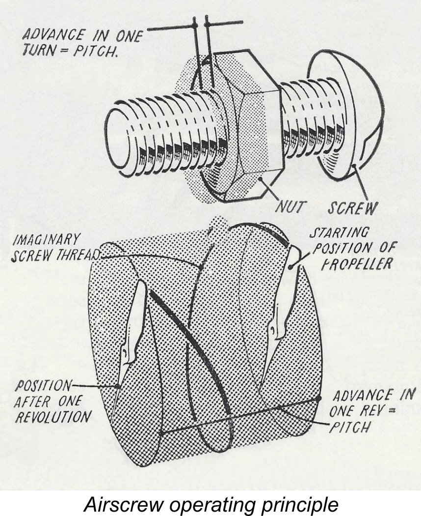
 This formula has been around for decades now and has stood the test of time pretty well. I would seriously question its validity for the kinds of rotational speeds now being reached with piped speed engines. It’s likely also less reliable for very small props, which are almost certainly more subject to slippage than their more efficient larger relatives. Similarly, for high-drag models it probably gives somewhat inflated results. However, for those like me who tend to fly conventional mid-sized classic equipment at less than astronomical rpm using mid-sized or larger props (8 inch diameter or larger), experience has shown that it works surprisingly well. It can be extremely useful when it comes to selecting the optimum prop for a given motor/model combination.
 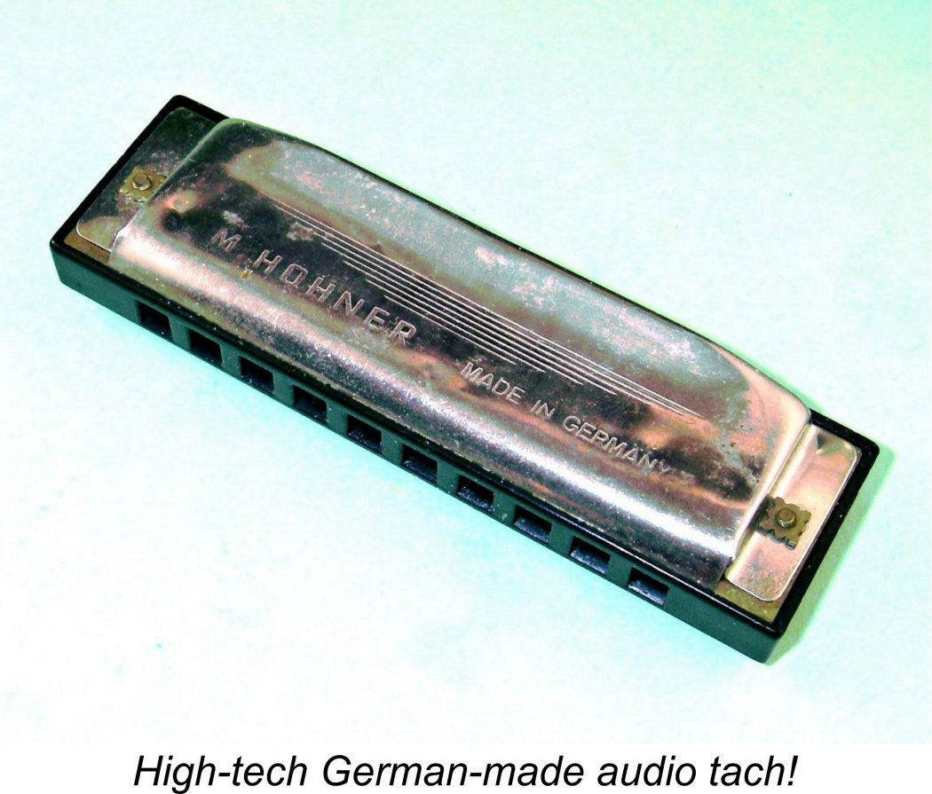 Having done our best to optimize our equipment, it’s nice to be able to measure the results to see how well we did. Measuring lap times is easy, and lap times on a given line length are easily converted into speeds in mph or whatever you prefer. Again, I won't bore you with the calculations - suffice it to say that the formula:
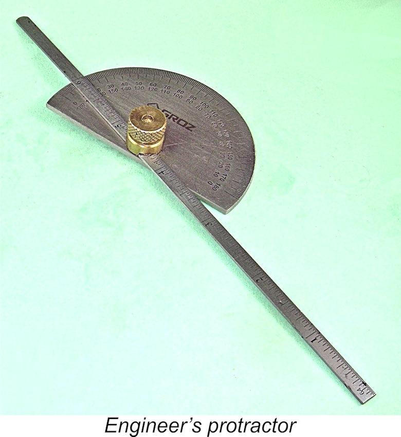
| |