
|
|
The Ace 0.5 cc Diesel
I’ve previously covered the Ace in an earlier article which appeared in January 2009 on the late Ron Chernich’s fascinating “Model Engine News” (MEN) website. So why the re-publication here?!? Firstly, because my mate Ron unfortunately left us in early 2014 without sharing the access codes for his heavily-encrypted website. Since no site maintenance has since been possible as a result, MEN is slowly but perceptibly deteriorating - an inevitable process which can have only one ending in the long run. I was unwilling to risk the loss of the information so painstakingly gathered on the little Ace. Secondly and perhaps even more importantly, I've become aware of a considerable amount of additional information about the engine since the publication date of my original article, over 17 years ago now (have I really been doing this that long?!?). This made it imperative for me to review the article with a view towards bringing it up to date on the basis of the best current information. Hence the article’s re-publication here. Although the Ace was mentioned and even illustrated from time to time in contemporary publications, I've been unable to find any detailed description of the engine in any of my source material, nor does its production history appear to have received any coverage. Consequently, this article represents an extremely belated first attempt to fully describe and evaluate this cute little motor, over 80 years after its introduction!
The identity of the actual manufacturer cannot now be determined. It’s also unclear whether the appearance of the Ace resulted from an initiative by Harry York himself or from an approach to Harry York by the unknown manufacturer. The designer(s) of the engine may have developed the design independently on their own account, subsequently reaching an exclusive distribution agreement with York to market their product. Whatever the facts of the matter, the result was the April 1947 appearance of the Ace 0.5 cc diesel which forms the chief subject of this article. The little Ace undoubtedly enjoys the distinction of having been the first British production engine of 0.5 cc displacement, The Ace remained the sole half-cc British diesel until the introduction of the 0.55 cc Allbon Dart Mk. I in late 1950 heralded a spate of further half-cc productions from Elfin, FROG and E.D. (and much later, Allbon-Saunders). A proud heritage! For the purposes of the present article, I’ll focus on the Ace 0.5 cc diesel. Let’s begin by following the media trail which marked that engine’s tenure on the British market. The Ace 0.5 cc Diesel in the Contemporary Media
The first actual advertisement for the engine appeared in the June 1947 issue of “Model Aircraft” citing a price tag of £4 10s 0d (£4.50). Other advertisements for the engine followed. All of the primary advertising for this engine was placed in the name of Harry York’s Model Aircraft Supplies Ltd. retail business located At this time, Britain was blessed with two excellent monthly publications dedicated to aeromodelling - “Aeromodeller” and “Model Aircraft”. The latter was officially styled as "The Journal of the Society of Model Aeronautical Engineers (S.M.A.E.)". A prestigious title, since the S.M.A.E. was the body responsible under the oversight of the Royal Aero Club for sanctioning competitions, rule-making, records, etc. relating to model aircraft.
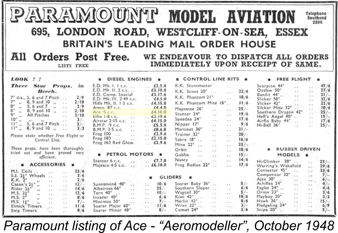
Nonetheless, the engine did appear in the pages of “Aeromodeller” in the lists of a number of retail businesses which advertised there. These included Paramount Model Aviation of 695 London Road, Westcliff-on-Sea, Essex. The first appearance of the Ace in their listing of available products was in the April 1948 issue, carrying the same price tag of £4 10s 0d (£4.50) as listed earlier by Model Aircraft Supplies. The engine remained in Paramount’s list each month through October 1948, followed by one isolated later appearance in May 1949. As far as I can discover, the latter inclusion appears to have been the final advertising mention of the Ace. Presumably this was an effort to clear unsold New Old Stock.
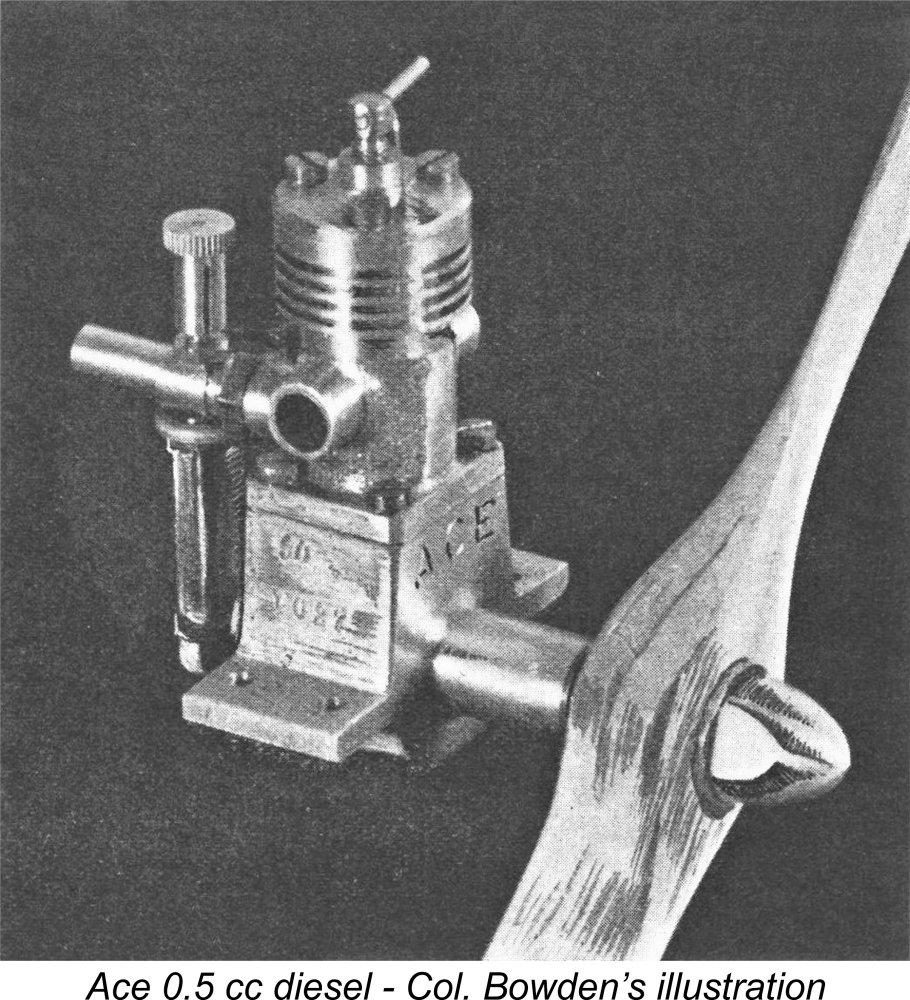
In all cases, the advertised price remained unchanged at £4 10s 0d (£4.50). This makes it clear that although the Ace was effectively a “house design” for Model Aircraft Supplies Ltd., that company was perfectly willing to supply other retailers, presumably at a wholesale discount. Given Harry York’s loyalty to “Model Aircraft” with respect to his own advertising, it’s scarcely surprising that the magazine took advantage of any opportunity to support their loyal advertiser. Their regular contributor Col. C. E. Bowden provided a testimonial which was included in Harry The Colonel also included the Ace in the September 1947 first edition of his book entitled “Diesel Model Engines”. In the latter work, he identified the originator of the Ace as his “old aeromodelling friend H. York”. However, he gave no other details regarding the manufacturing origins of the engine. He did however include a nice photograph of the engine, which is reproduced below in its place. The Ace appeared in the table of available commercial British diesels as of spring 1948 presented by D. J. Laidlaw-Dickson in the March-April issue of “Model Mechanic” magazine. However, it was not mentioned at all in the text. Laidlaw-Dickson actually commented that the AMCO .87 diesel was then “the smallest (engine) in anything like quantity production”. Since he was clearly aware of the Ace, the very obvious implication is that he considered it to be a limited-production artisan offering as opposed to a series production model.
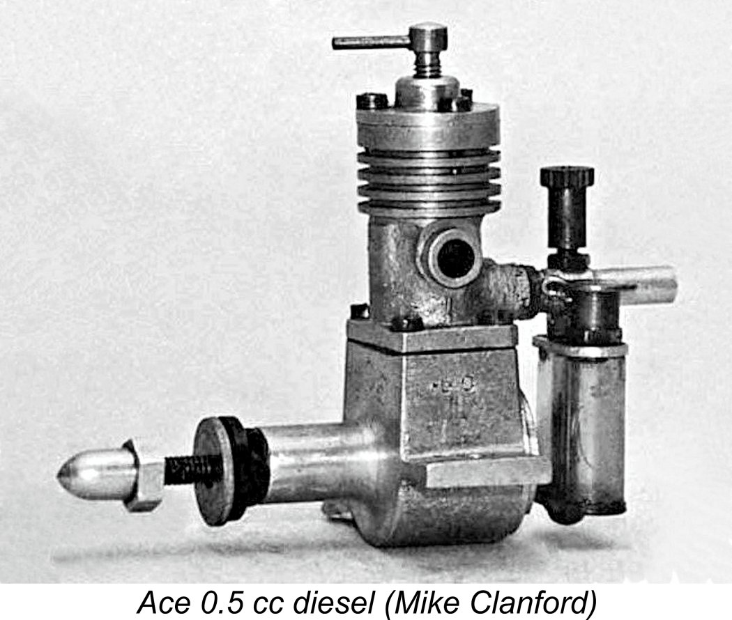
The final mention of the Ace in the British modelling media that I can find was the note which appeared in the October 1949 issue of "Model Aircraft" as one of their "Meet the Contributors" features, this one on the subject of J. Marshall, then Secretary of the Haynes & District M.A.C. The text recorded the retrospective fact that in 1948 Marshall had established the first British Tailless Power Record with a duration of 83.8 seconds using an Ace 0.5 cc diesel. So the Ace had its moment in the sun!! Taking all of the above information into account, it seems safe to say that Britain's first ½ cc diesel appeared in April 1947 and remained on offer thereafter in minimal quantities for perhaps 17 months, albeit almost certainly not being manufactured throughout that entire period. Despite the almost vanishing rarity of the little Ace, its existence has been noted by more recent authors. It was mentioned almost in passing by O. F. W. Fisher in his 1977 book "Collector's Guide to Model Aero Engines". Mike Clanford also took note of the Ace in his useful but frequently unreliable "Pictorial A-Z of Vintage and Classic Model Airplane Engines" of 1987. He included a nice photograph of the engine, although he got the month of its introduction wrong. Finally, Ted Sladden included a fine photograph by Kim Watson of an example of the Ace complete with box in his 2014 book "British Model Aero Engines 1946-2011". The Ace 0.5 cc Diesel Described
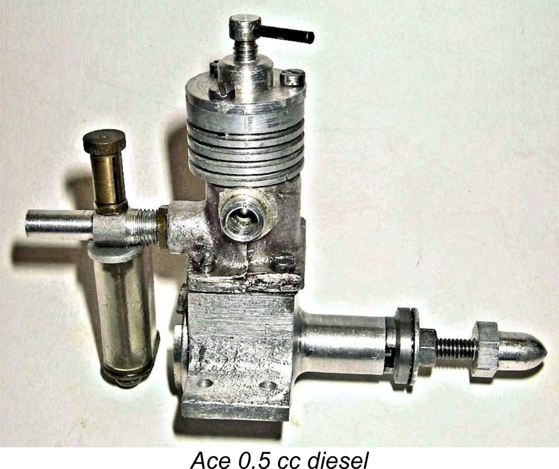
Beginning with the basics, the Ace 0.5 cc diesel features the usual long stroke of its side-port contemporaries, with a measured bore (in the case of my example) of 7.65 mm and a stroke of 11.00 mm for a stroke/bore ratio of 1.44 - a figure exceeded only by the Foursome and Kalper engines in my experience. These dimensions yield a displacement of 0.506 cc. The engine weighs in at a checked 2.125 ounces or 60 gm, complete with tank.
A major focus of these historical essays of mine must always be to correct any mis-information that may be out there. In that regard, it is necessary to set O. F. W. Fisher straight regarding the construction of this engine. On page 41 of his book, he stated that the case was machined from the solid. Despite this, both the illustrated example from my own collection and the two other examples that I have examined elsewhere feature sandcast cases. It is of course quite possile that all three of these examples were replicas. These crankcase castings are machined over much of their external surface as well as internally – in fact the only un-machined exterior surfaces are the top of the mounting lugs and the sides and underside of the crankcase. The sides of the case on my example have been rather crudely filed, presumably to eliminate some casting scale or flash. The undersides of the very substantial beam mounting lugs are neatly machined to ensure a secure parallel mounting.
Porting is quite rudimentary. Beginning with the induction arrangements, there are two very small circular induction ports drilled adjacent to each other at the rear of the cylinder liner. These communicate with the internally-threaded induction tube boss at the rear of the cylinder casting. The twin induction ports open fairly early as the piston rises, resulting in a relatively long induction period which presumably helps to compensate for the ports’ small size. On my example, the two ports are drilled at slightly different levels in the liner, as a result of which their opening is staggered to a degree. It’s possible that this was a design feature - the near-contemporary Mills .75 diesels displayed this feature, seemingly by design based upon the surviving tooling held by the Kumar family in India, but to me it seems more likely that it was an incidental error in the manufacture of this particular example. This is in keeping with the rather “hand-made” appearance of the engine in general terms. Transfer is accomplished through a pair of similar-sized drilled holes through the front of the cylinder liner. These holes are fed through a single transfer passage machined into a cast-in “bulge” at the front of the cylinder casting (clearly visible in the front view). The very small transfer ports open very late indeed, hence giving the impression that they should represent a On the face of it, this arrangement is a clear recipe for inefficient transfer and scavenging. In fact, the transfer arrangements appear on detailed examination to represent the main limiting factor with respect to this engine’s potential performance. But see on for performance comments below …………. The provision of induction and transfer ports drilled fore and aft in pairs is probably due mainly to the desirability of ensuring that the gudgeon pin cannot foul these ports. As matters stand, the thin column of material between each pair of drilled ports is aligned with the gudgeon pin, thus preventing it from hanging up in the ports. Exhaust ports consist once again of two adjacent drilled openings on either side which communicate with round exhaust bosses machined into the sides of the cylinder casting. However, these ports are quite substantial in size – one is forced to wonder why the induction and transfer systems weren’t similarly free-breathing. The exhaust ports open relatively late but still well before the transfers, giving a seemingly adequate blow-down period prior to the commencement of the transfer phase of the cycle. This doubtless aids the scavenging process. The fuel supply system is of some interest. The choke tube is a simple turning from bar stock aluminum which screws into the mounting boss at the rear of the cylinder casting and is secured by a brass lock-nut. It can thus be oriented together with the tank in any desired position. The choke tube has a very nice In keeping with many contemporary British engines, there is no spraybar. Instead, the needle valve thimble screws onto an externally-threaded brass spigot which is drilled to pass the needle and is threaded independently into one side of the choke tube, ending more or less flush with the internal surface of the venturi. The separate brass fuel pick-up tube screws into the opposite side of the venturi. The needle simply passes through the spigot and across the otherwise-unobstructed throat section of the venturi to engage with the jet in the fuel pick-up tube on the other side – in effect, a standard surface jet needle valve system. The needle valve thimble is tensioned by being split in the usual manner. The brass fuel pick-up tube extends down to the base of the tank. A threaded portion protrudes through the tank base to allow the tank to be secured using a very neat acorn nut. A nice touch is the use of a gasket underneath this acorn nut to eliminate any chance of a fuel leak – potentially disastrous in such a small tank as this. Two small holes are drilled horizontally into the pick-up tube at the tank base to supply fuel to the system. A threaded portion of the pick-up tube at the top screws into the choke tube opposite the needle mounting, and a nut mounted on the exposed portion of this thread within the tank serves both to lock the system in place and to secure the aluminium tank top to the choke tube in any desired orientation. Again, very neat!! The engines were fitted with a Partridge filler cap which was missing from my example as received. The plastic tank itself is well worthy of comment. It has a most unusual narrow “race-track” section, as can be seen in the photographs, almost like a section cut from a plastic toothbrush tube! I assume that there are two reasons for this. One would be to ensure that the tank drains to the “last drop” regardless of the attitude of the model during its climb, and the other would be to create a constant and (more importantly) relatively small section so that motor runs could be timed with sufficient accuracy for sport free-flying (for which the engine is clearly intended) by noting the appropriate level in the tank at which to launch – not so easy to do accurately with a tank of larger section and greater horizontal extent.
A few more descriptive points – the one-piece hardened steel crankshaft is very well machined and finished. There is no attempt at counterbalancing – a plain disc crankweb is used. The shaft fit in the main bearing is superb – very free, but with no detectable trace of play, even when dry. The bearing itself is bronze-bushed, hence having the potential to outlast the rest of the engine by a country mile. The rod is of hardened steel, in common with many British engines of the period. Here the design can be fairly criticized on the grounds that there is far too little material at the small end of the rod, resulting in a bearing on the gudgeon pin that is far shorter than ideal. I would expect this end of the rod set-up to wear fairly rapidly, although the engine’s small bore and relatively modest performance would doubtless do much to delay the onset of any such effects. Another criticism that may be mentioned at this point is the main bearing housing. This appears to be rather flimsy given its very thin walls along with the complete absence of any supporting webbing. However, any model in which this engine might be expected to be used would have been both slow and light, with commensurately low crash stresses. So perhaps all would have been well in actual use. In the illustrated example, the fit of the cast-iron piston in the steel cylinder is again truly superb – no trace of excessive friction (a real killer in the smaller sizes) but also an outstanding compression seal. The cast-iron contra-piston is also extremely well fitted. Overall, I have to say that despite its rather rough-and-ready external appearance, the engine is extremely well made where it counts. An unusual feature of the Ace is the fact that the comp screw is of aluminium alloy, with a steel tommy bar. The comp screw naturally operates in the machined alloy head. I must confess that light alloy running under stress in light alloy has never recommended itself to me as an ideal combination. There’s little or no detectable wear on the illustrated example, but this can readily be explained by the fact that this particular unit has never been mounted, actually appearing to be almost unused.
The provision of the conventional prop nut and steel washer along with the cute little alloy spinner nut is interesting. I don’t even know if this spinner nut is an original feature, but assume that it probably is – I’ve seen several other examples with exactly the same accessory, including the example illustrated by Clanford. The illustrated example from my own collection bears no identification and no serial number. This is in contrast to the one pictured on page 41 of Col. Bowden’s book, which has the name “ACE” stamped onto the front of the case and also has a serial number stamped into the right side of the upper crankcase above the mounting lug. The explanation for this is obscure. One possible inference is that the engines were inscribed at the outset but that this practise was discontinued later, most likely for reasons of cost. The example illustrated by Bowden must be one of the earliest examples made, and the makers may have taken more trouble to identify their product with the introductory “ambassador” models than they did later.
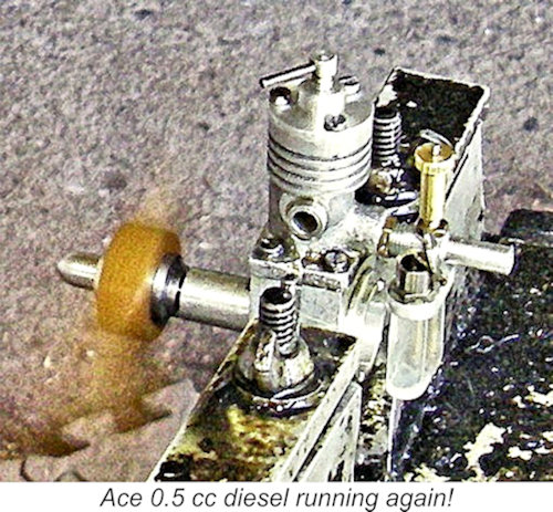
However, my example is definitely not one of Derek’s efforts, since his replicas were based upon crankcases machined from the solid, while my example is definitely built around a cast crankcase. There are numerous other obvious detail differences in addition. At the time of writing I am not aware of any other replication effort with respect to the Ace, although a few one-off replicas have almost certainly been made. Getting back to the issue of serial numbers, I have only three such confirmed numbers at present. These are no. 1027 (Col. Bowden’s presumably early example); no. 1138 which appeared on eBay in 2022; and no. 1146, a photograph of which by Kim Watson appears in Ted Sladden’s previously-mentioned book. Although this is a statistically unreliable sample size, there is a clear implication that the serial number sequence started at engine The fact that Col. Bowden was able to include a photograph of engine no. 1027 in his September 1947 book which must have gone to press only a few months after the engine’s introduction appears to me to represent overwhelming evidence to support the above possibility. The alternative would be to credit the manufacturers with making over 1000 examples between March and June 1947 (allowing for Col. Bowden’s publication lead time) - not really credible. If we accept the strong probability that the serial numbers started at 1001, we appear to have evidence for the production of some 150 examples in total. There may very well have been more, but only the reporting of higher confirmed serial numbers could increase this estimate. Any volunteers ……?!? Whatever the true figure, it was certainly pretty small, explaining the engine’s extreme rarity today. It seems extremely doubtful that production got anywhere near four figures. Regardless, how does it run?? Let’s look at that aspect of the Ace next! The Ace 0.5 cc Diesel - Operational Characteristics I hadn't tested my example of the Ace in recent years - time has been a hard taskmaster! However, I did run a few test props past it back in 2008 in support of the original draft of this article on MEN. The test figures recorded on that occasion seemed a little high to me - this was relatively early in my testing career! This being the case, I decided to run a full re-test in support of this updated article. Prior to doing so, I had sent the engine down to my good mate Dean Clarke in New Zealand to have an accidentally-broken fuel system repaired - mea culpa! While he was at it, Dean also replaced the somewhat inadequate con-rod and rebored the engine, all to his usual extremely high standard.
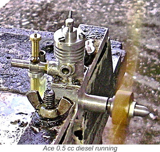
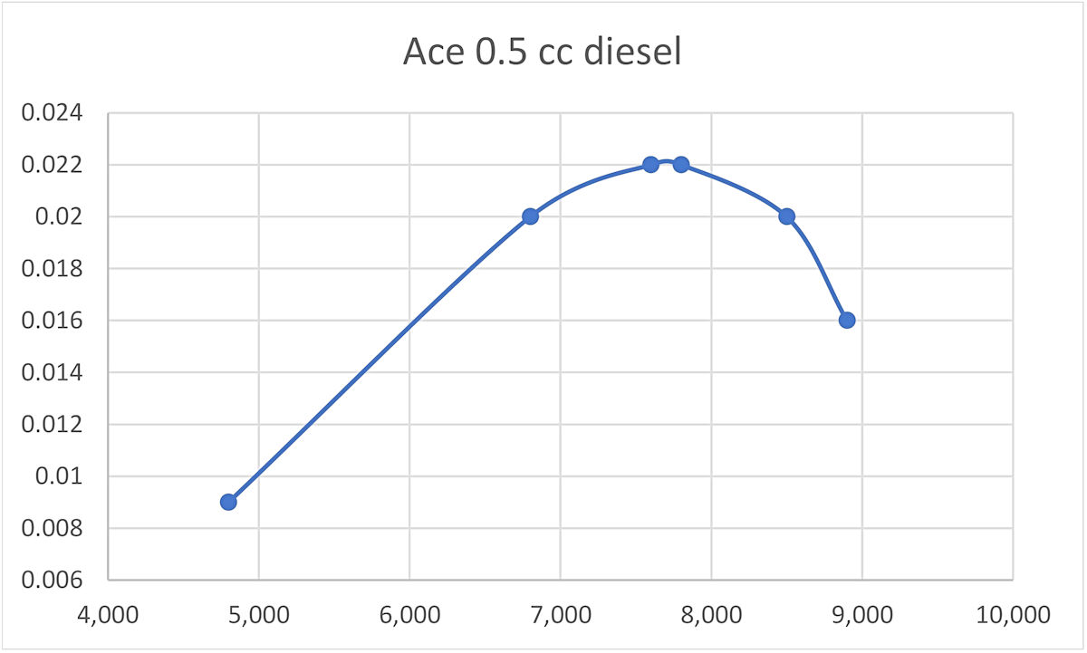
Once going, the engine ran very smoothly indeed – no indications of transfer strangulation here! It also responded unexpectedly well to the controls – the optimum settings were dead easy to establish, while the engine could be throttled back very effectively and dependably with the controls, which would have been a great advantage for trim flights, etc. On a rich needle with reduced compression, it kept running quite smoothly and dependably, albeit a lot more slowly. The small tank supplied with the engine gave a leaned-out full-power run of some 80 seconds – plenty for the sport free-flight applications for which the engine was doubtless intended. A small bottle of fuel (fuel was often supplied in bottles in those days!) would have provided a lot of flying with this engine! OK, how did the engine perform once running? Well, it’s now time for me to do some grovelling with respect to all the comments that I made earlier about the anaemic breathing of this engine. As I think I’ve made quite clear, it really has no business running with the slightest hint of performance …………… but darn it, just to spite me, the thing did run that way after some 20 minutes of running-in time!! It displayed a willingness to run at significantly higher speeds than I had been expecting! The following data tell the story.
Frankly, I was not expecting the Ace to peak at around 7,800 RPM! It also did considerably better than the manufacturers' claims in terms of prop speeds. The previously-reproduced introductory advertisement of April 1947 cited operating speeds of 4,500, 5,000 and 6,000 RPM with 8 in., 7 in. and 6 in. dia. airscrews respectively. The test example beat all of these figures quite handsomely, although it's admittedly true that the airscrews cited in the advertisement were likely higher-pitch items. Regardless, the peaking speed implied by the advertised figures falls well short of the reality! The peak output of 0.022 BHP may seem rather unimpressive, but it's really not a bad figure for a simple side-port ½ cc diesel of this vintage. A 7x4 prop would appear to be a perfect match for the engine.
There’s no point in trying to push the Ace to run too fast by going to 6 in. dia. props - it’s pretty much done by 8,500 rpm. Better to use a somewhat larger prop and take advantage of the engine’s low end torque rather than its peak power. A 7x4 prop that pulls the static revs down to around 7,000 - 7,500 RPM or so would appear to be the ideal prop to use – the engine clearly has the torque to deal effectively with such a size. At this point I have to confess that Col. Bowden and I are not in agreement on the subject of props to use with the Ace! The gallant Colonel was always a fan of running his engines at low revs regardless of their actual peaking speeds, and he used an 8 inch diameter propeller of unspecified pitch on his Ace, noting on page 42 of his book that it turned that prop at 4,500 rpm, just as claimed by the manufacturer!! Sounds quite believable, but it’s clear from my own testing reported above that the Ace was at its best running a lot faster than that and that an 8 inch airscrew would definitely over-prop it in terms of achieving maximum available performance. A point that is very much in the engine’s favour is the noise level – the relatively late exhaust opening means that it’s remarkably quiet, even having regard to its small size. The use of drilled exhaust ports doubtless has something to do with this too, since drilled ports open progressively rather than all at once, and on this design they open quite late after the combustion gases in the cylinder have had a good chance to expand and hence lower the exhaust pressure in the cylinder while driving the prop for an extended period. Whatever the reason, the operation of this engine would have created few complaints about noise!! Conclusion
Still, an interesting and well-made little engine which is a pleasure to operate and which led the way towards the development of smaller British-made engines, being thus richly deserving of our recollection and respect. It is completely unpretentious when it comes to the surface trimmings but is very well made in the essential areas and runs with surprising vigour. The design could doubtless have been improved still further by freeing up the transfer process and thus improving scavenging, but as a quiet and flexible sport flyer the Ace 0.5 cc offered its owners all that was required by the standards of its day. A gold star to Harry York!! __________________________ Article © Adrian C. Duncan, Coquitlam, British Columbia, Canada First published on MEN January 2009 Revised edition published here August 2026 |
||
 In this article I’ll share an in-depth look at another relatively obscure and hence little-known British diesel engine from the early post-WW2 years. I'll be examining the Ace 0.5 cc diesel which appeared in early 1947, thereby initiating a trend towards the production of a series of commercial sub-miniature diesels by a number of competing manufacturers.
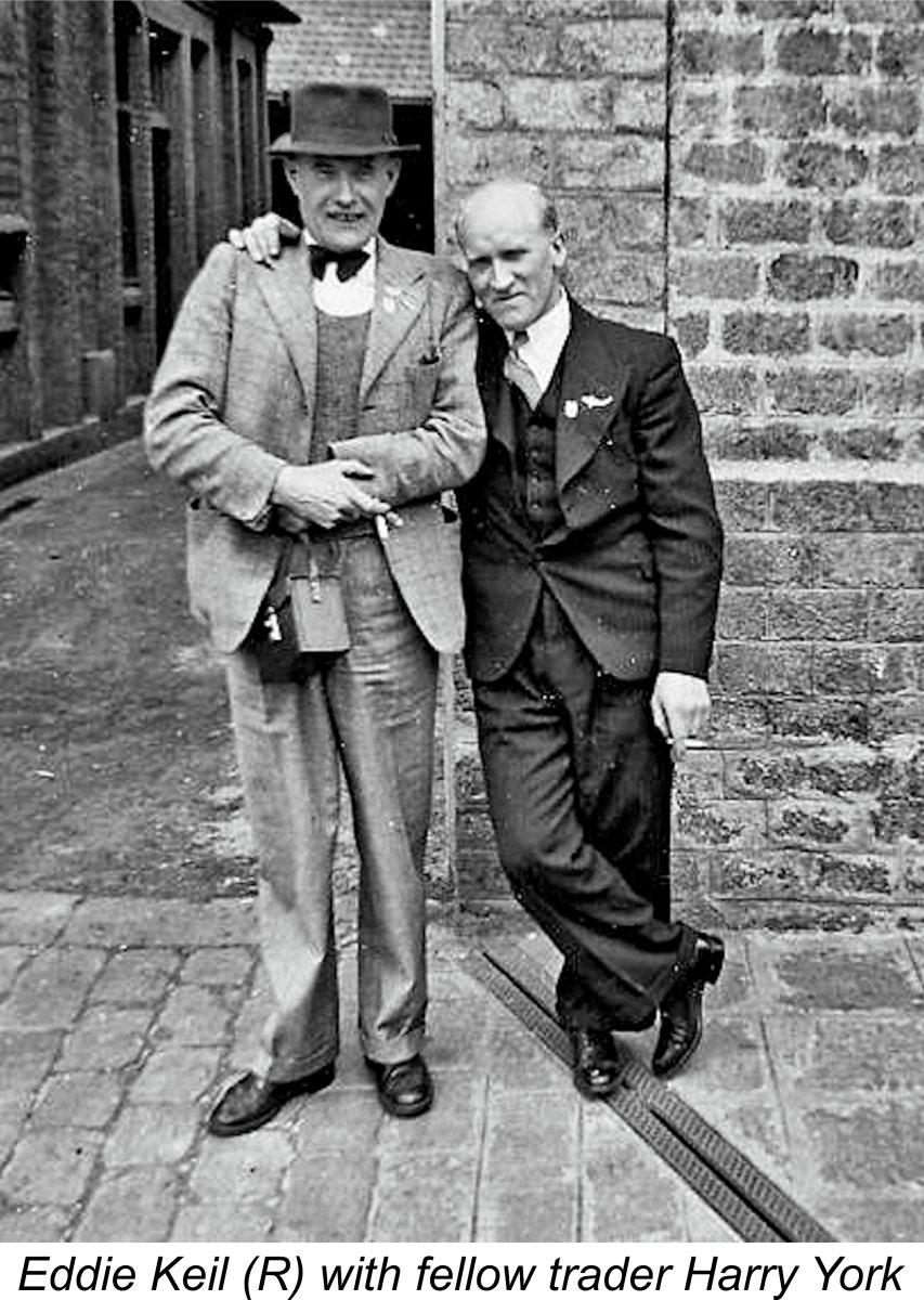 The origins of this intriguing little power unit are now extremely obscure. It was undoubtedly promoted from the outset by a friend of Eddie Keil named Harry York, who owned and operated a retail model shop known as Model Aircraft Supplies Ltd. located at 171 New Kent Road in London S.E.1. As far as is known, Harry York was not a manufacturer per se, making it appear highly unlikely that he was the actual manufacturer of the Ace. However, the name of his company appeared on the boxes in which the engines were sold.
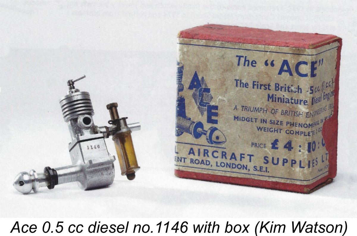
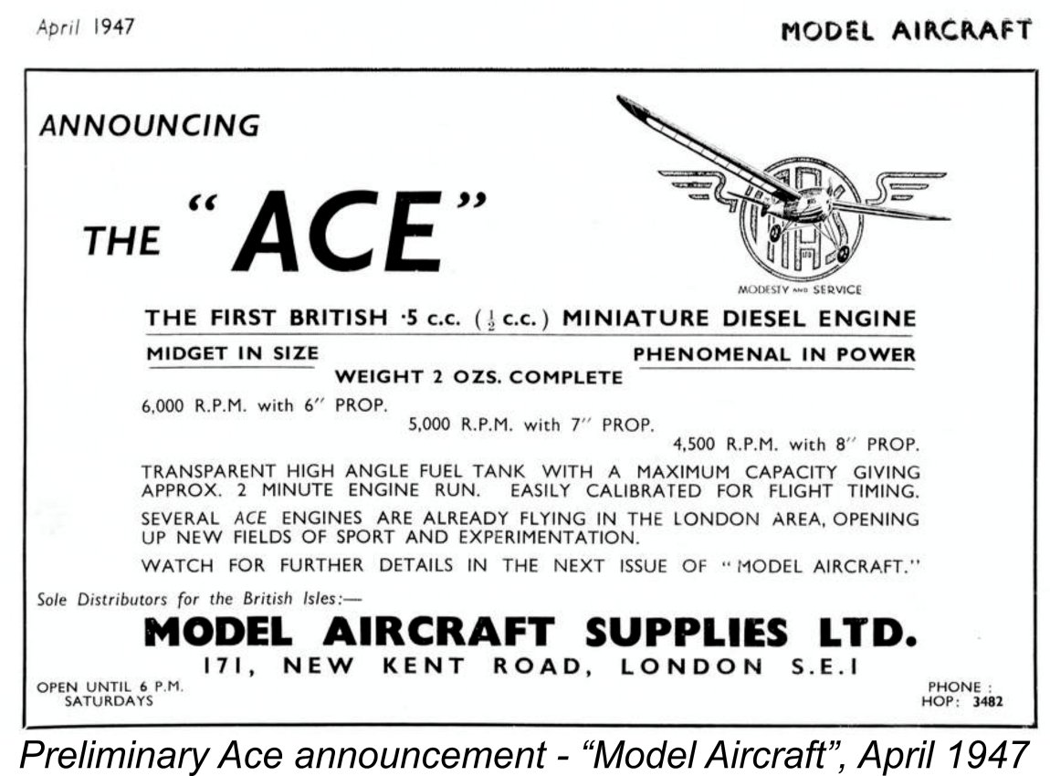 The first media announcement for the engine that I've been able to find appeared in the April 1947 issue of “Model Aircraft” magazine. Allowing for editorial lead time, it must have been submitted in February 1947. This one-third page splash was actually a preliminary announcement, although it stated that prototypes were already in the field at that time. Note the clever interplay of the company name’s leading letters MAS in the logo, as well as the tie-in to the initials of the company motto “Modesty and Service”. Someone put some thought into that!
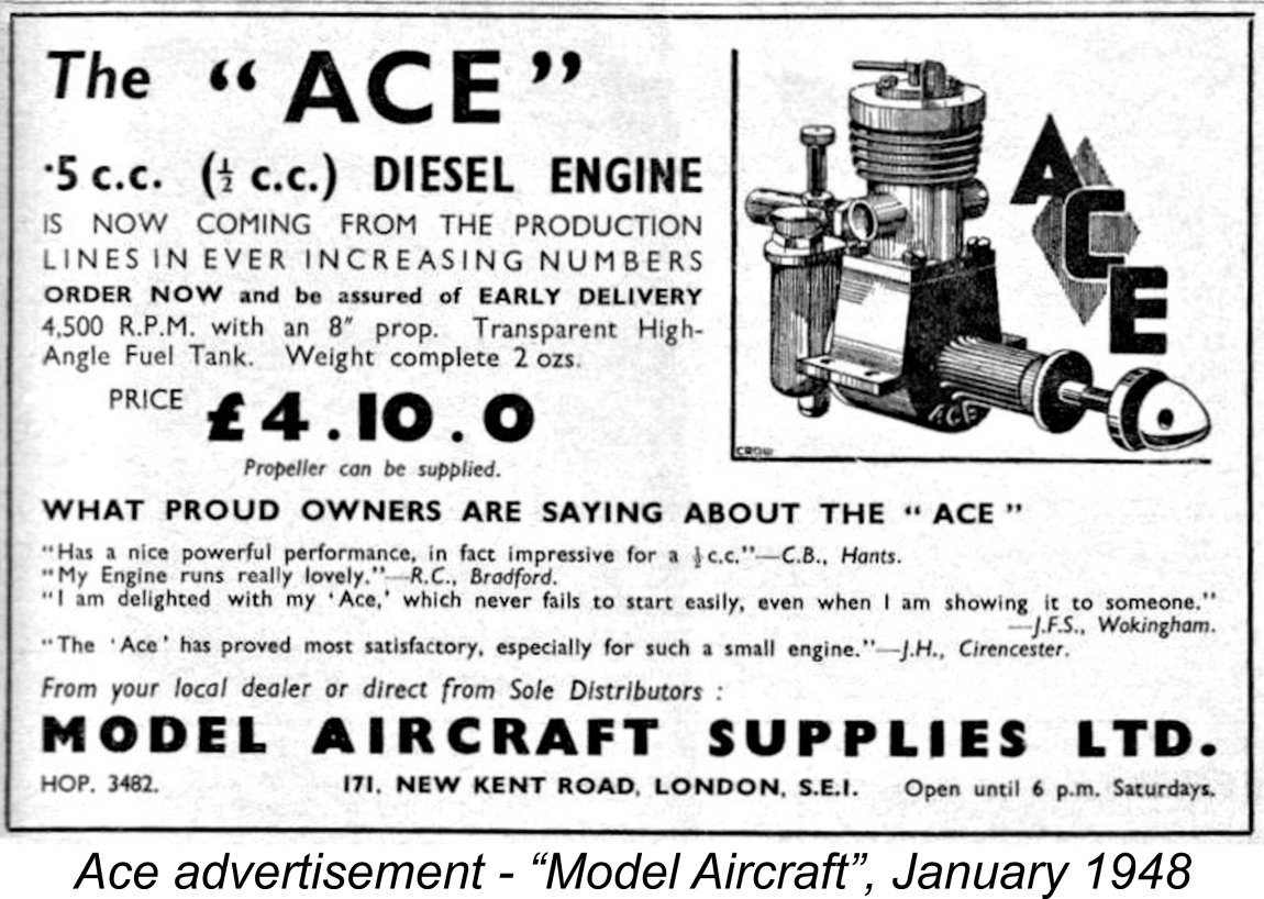
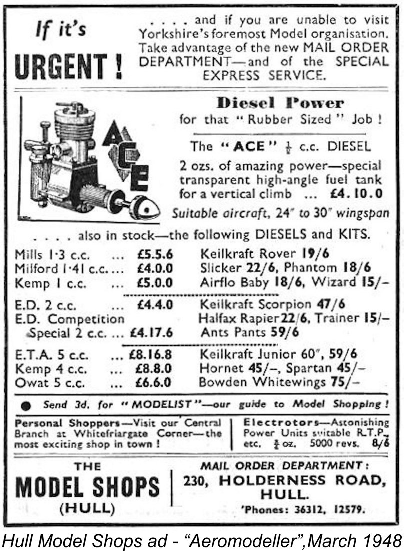 The Ace also appeared in Henry J. Nicholls Ltd.’s “Aeromodeller” advertising, albeit once only in their February 1948 placement. The engine was also offered by The Model Shops (Hull) of 230 Holderness Road in Hull, appearing in their March 1948 advertisement in “Aeromodeller”. That advertisement actually featured the Ace, which was assigned its own illustrated panel in the layout.
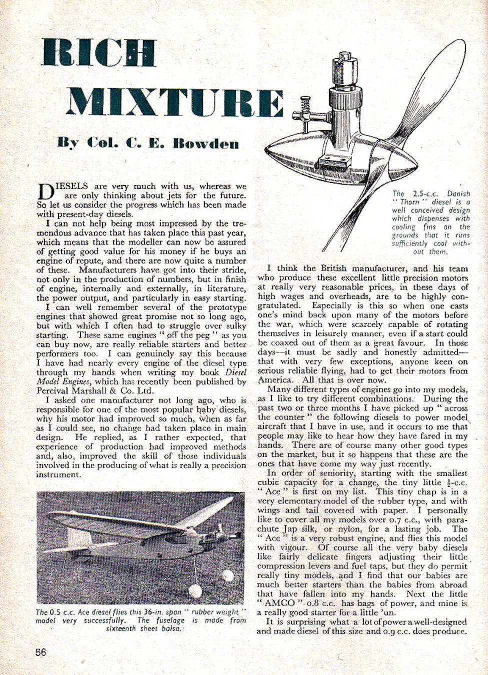
 Another contemporary author who mentioned the Ace was Ron Warring, who listed the engine in the table of British diesels which formed an Appendix of his early 1949 book “
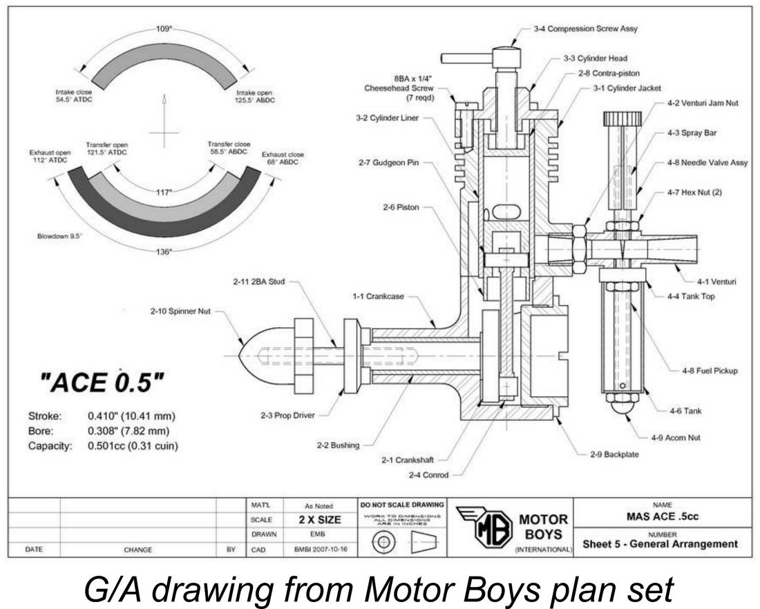 Some years ago, my late and greatly-missed mate Ron Chernich produced a set of plans for the Ace on behalf of
  When compared with its later ½ cc descendants, the Ace is undoubtedly on the bulky side and carries a fair bit of excess weight to boot – the original 1950
 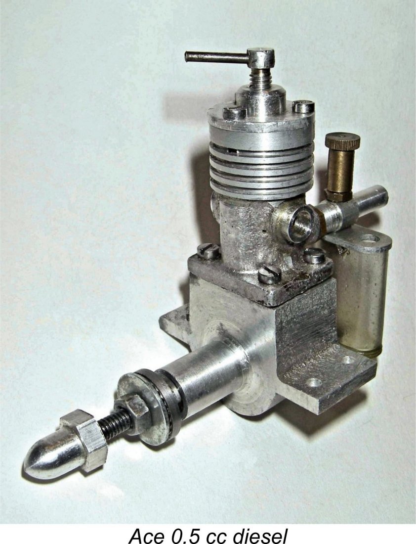 The only other casting used is that for the cylinder jacket. This is a rather agricultural-looking job with a certain lack of “tidiness” about it, especially at the parting line. The liner appears to be shrunk into this casting – at least, I can see no evidence of any other means of securing it. The bore was presumably finished after the shrinking-in process was complete. I‘ve never tried to disturb the liner, so I can’t comment further on this point.
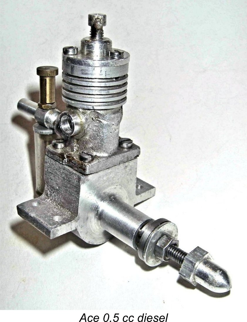 considerable impediment to the engine reaching high speeds. Unlike the contemporary
 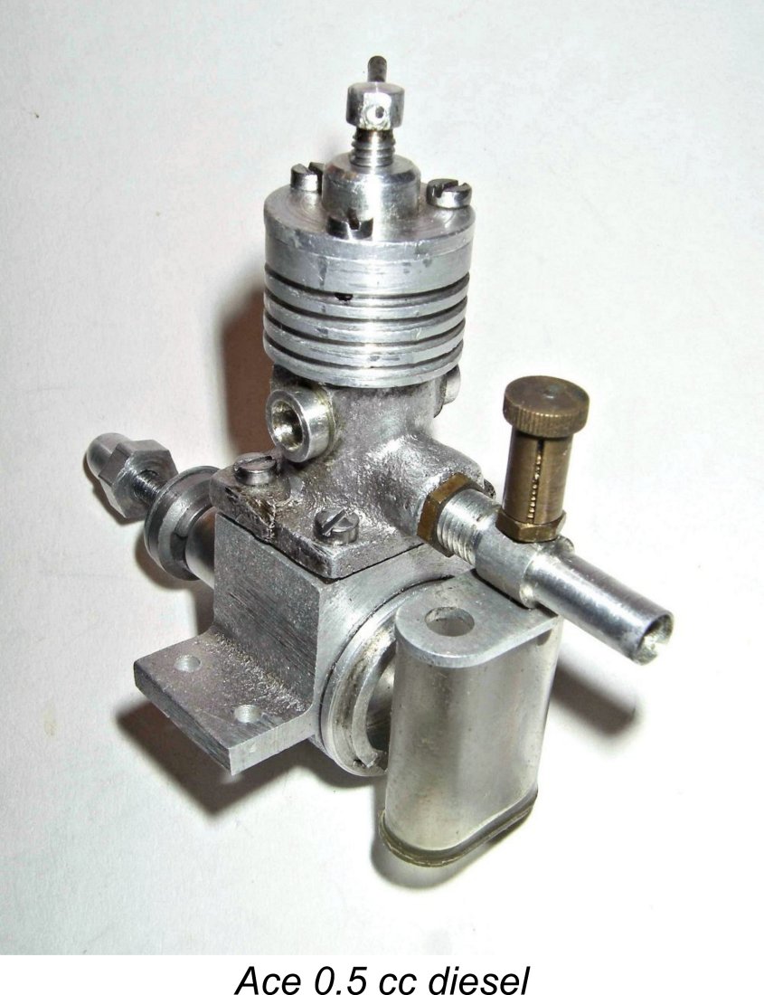 venturi section which tapers down from the rear to a constriction at the needle location and then opens up again towards the induction ports – very elegant!
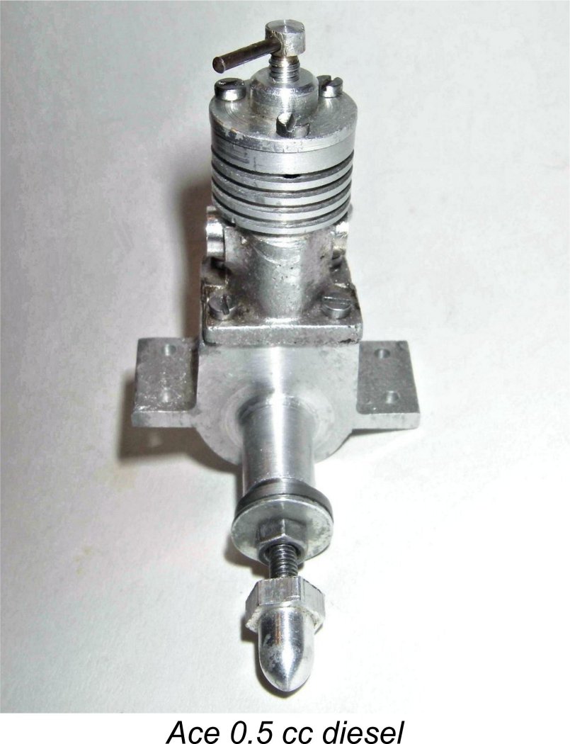
 The steel prop driver is slotted at the rear to engage with a pair of flats machined in the front of the shaft where it protrudes from the main bearing. I prefer a taper fit here – the arrangement used in this engine appears to me to create a substantial stress-raiser at the front of the shaft. But the
 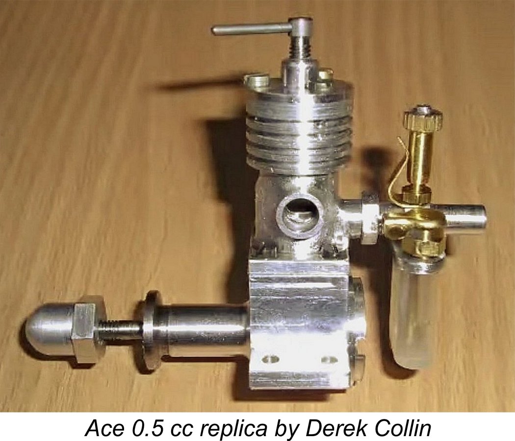 The other obvious possibility is that my own example is a very convincing repro made at some point by person or persons presently unknown ………….. if so, it’s quite a bit more “agricultural” than the typical latter-day repro! In that regard, I am aware that Derek Collin made a handful of outstanding replicas of the Ace, incorporating a number of internal modifications including the replacement of the twinned exhaust holes with oval apertures. He appears to have followed the previously-mentioned Motor Boys plans.
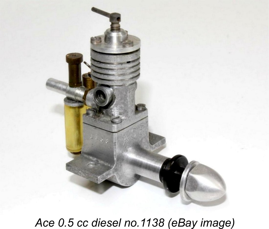
 With this level of performance, the little Ace would have made a very acceptable power plant for use in the small free-flight sport and scale models which were doubtless its intended application. Engines of such small displacements were actually seen more as replacements for rubber power than as serious powerplants in their own right. The Hull Model Shops advertising insert of March 1948 which was reproduced earlier put this very clearly, citing the Ace as representing “Diesel power for that “rubber sized” job”.
 It would be interesting to learn the manufacturing source of the Ace as well as the full extent of its distribution and the actual duration of its production period. Regardless, it’s hard to see how the engine could have survived the competition from
 | |