
|
|
A Canadian Expatriate - the Merlin Super “B”
The preparation of this article was greatly informed by an owner survey which was published in late 2021 in the indespensable "Engine Collectors' Journal" (ECJ) by its late and much-missed Editor Tim Dannels. I'm greatly beholden to Tim for his efforts, and also to all of his readers who responded. The Merlin was mentioned in the capsule survey of model engine manufacturing in Canada which accompanied my earlier review of the Canadian-made Monarch 600 racing engine. However, the level of detail was rather scanty, while no test figures were reported. This article will address those omissions.
Now, having acknowledged Mike’s contribution, it’s time to proceed with our tale! Background Canada is definitely not the first country that comes to mind when the subject of model engine manufacturing comes up. In large part this is doubtless due to the combination of two key factors. The first of these was the country's huge geographic area allied to a relatively small population, which created a very sparse population density and hence a highly fragmented domestic marketplace of no great overall size. The second factor was the presence of a ready source of competitively-priced engines which were produced to a high standard immediately south of the border in the USA and were readily available in Canada.
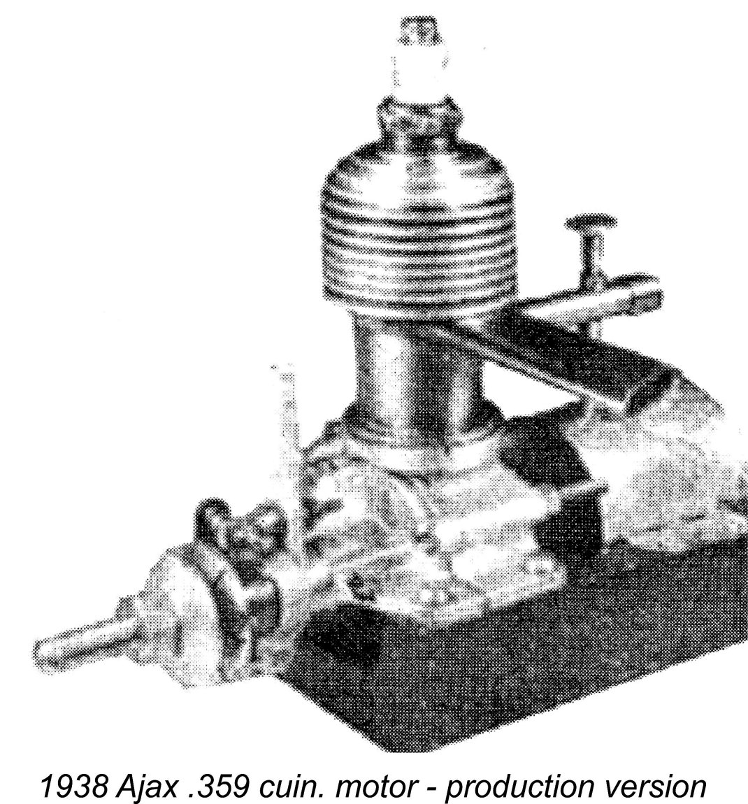
Although a few individual model engines were undoubtedly made in Canada by talented home machinists during the pre-WW2 period, there seems to be only one record of any commercial-scale series production being undertaken in Canada during those years. This relates to the Ajax .359 cuin. (5.88 cc) spark ignition model which was manufactured in Winnipeg, Manitoba in 1938-39 by one Arthur Jaques following some successful prototype testing in 1937. No prizes for guessing the origin of the Ajax name!! The Ajax engines were marketed through the St. John Model Shop in Winnipeg. The associated brochures specifically cited this engine as “the first motor to be manufactured in Canada”, seemingly confirming its priority. It was produced in very small numbers - no surviving examples are known today, just a few fuzzy photos to prove that it existed. Although Canada was actively involved in WW2 from September 1939 onwards, an enthusiast named Paul Drimmie of Toronto, Ontario somehow managed to produce a very small number of examples of a 0.607 cuin. (9.95 cc) sideport spark ignition engine called the Drimmie ”10” in 1940. However, this effort ended almost as soon as it had begun, doubtless due to the intrusion of other more pressing concerns. It seems that Drimmie never resumed model engine manufacture after the war.
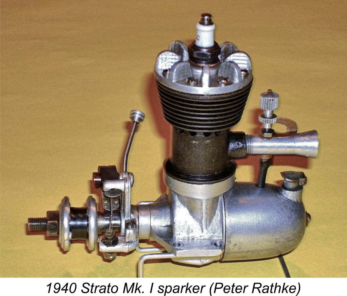
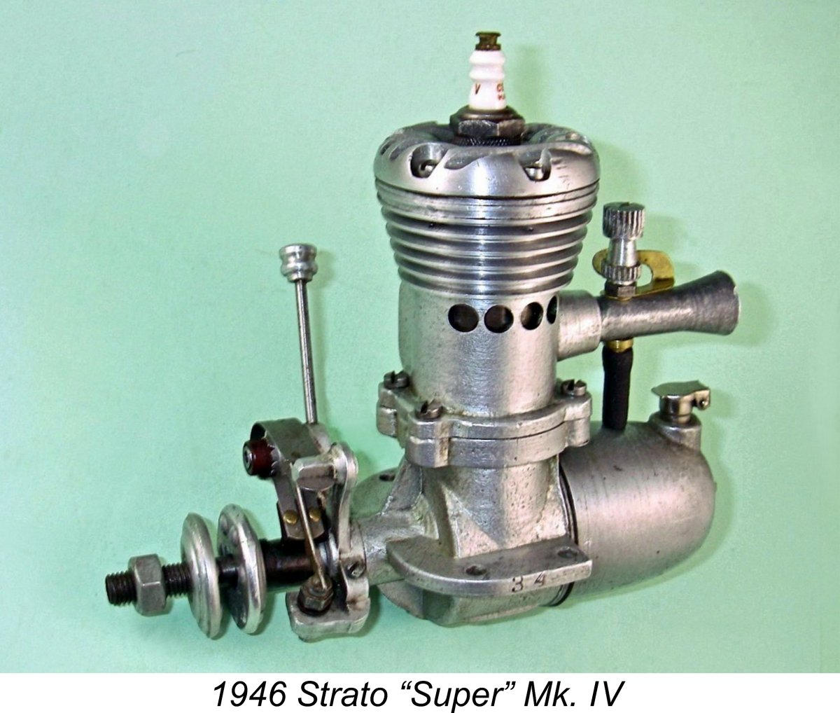
According to the genealogical information very kindly tracked down by Tim Dannels' son-in-law Sheldon Jones, Bainbridge had been born in northern England on January 1st, 1913 at Tynemouth, Northumberland but emigrated with his family to Quebec, Canada in 1925. He lived the rest of his life there, passing away in Montreal on March 7th, 2006 at the grand old age of 93. Beginning at the age of 27, Bainbridge somehow managed to construct two very small series of very high-quality 0.604 cuin. (9.9 cc) engines between 1940 and 1944 using the registered trade-name of Strato Model Engines. Around ten examples of the Mk. I version were completed, followed by eight examples of a slightly modified Mk. II version. These sideport units generally followed the design style for general-purpose engines which had evolved in North America during the nineteen-thirties. They were individually constructed to very high model enginering standards. Given the ongoing Canadian involvement in WW2, it’s unclear who Bainbridge’s customers may have been at the time.
Sadly, Bainbridge found that with his very limited production capacity based upon individual construction to very high standards he couldn’t compete in price terms with mass-produced American-built .60 cuin. alternatives such as the Ohlsson & Rice, Atwood, Herkimer (OK) and Super Cyclone units which became increasingly available in Canada following WW2. Not enough people were willing to meet the extra cost of the Strato engines’ tool-room quality. After some 40 examples of the “Super” Mk. IV sparker hadbeen manufactured, Bainbridge finally abandoned the model engine field, much to that field's loss.
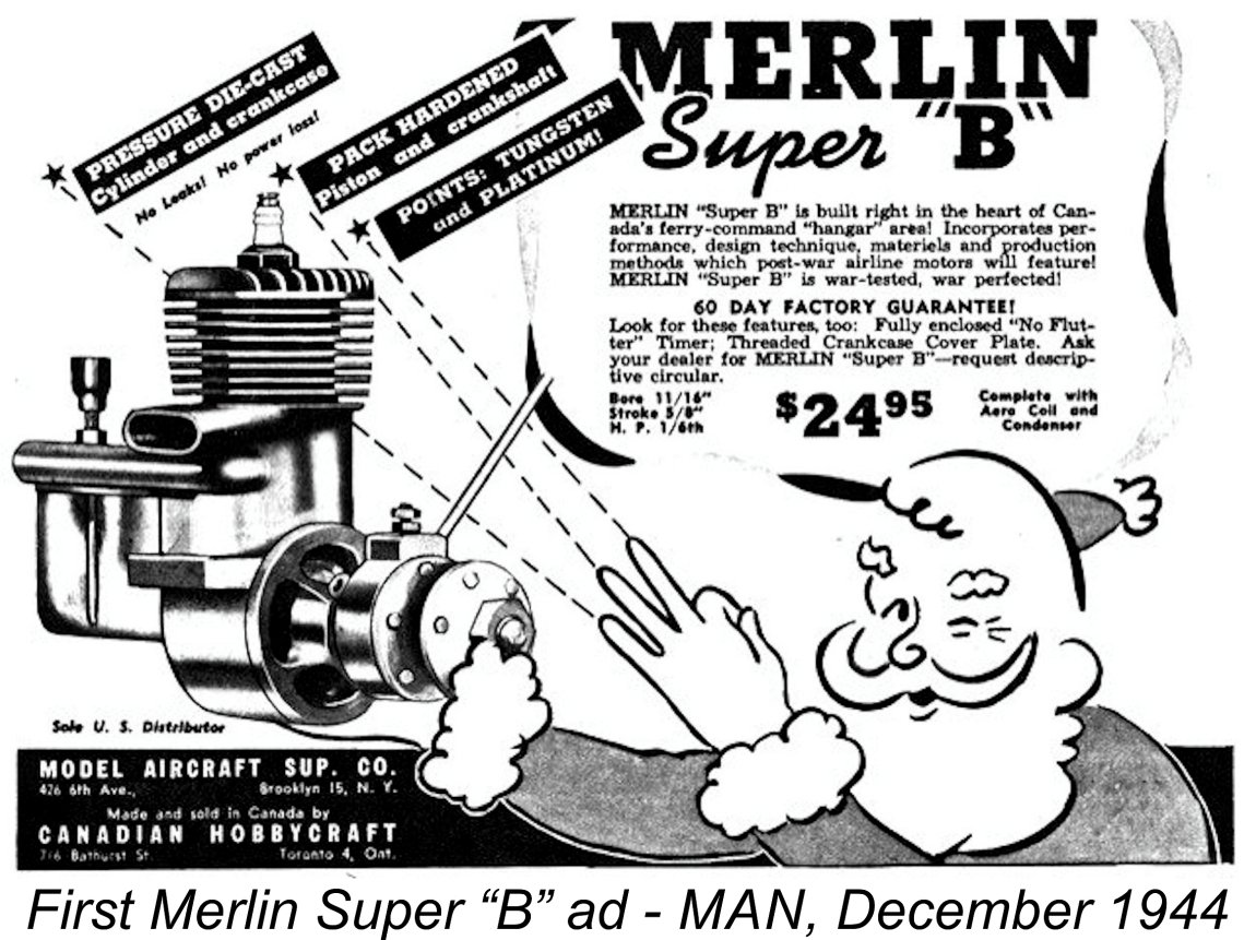
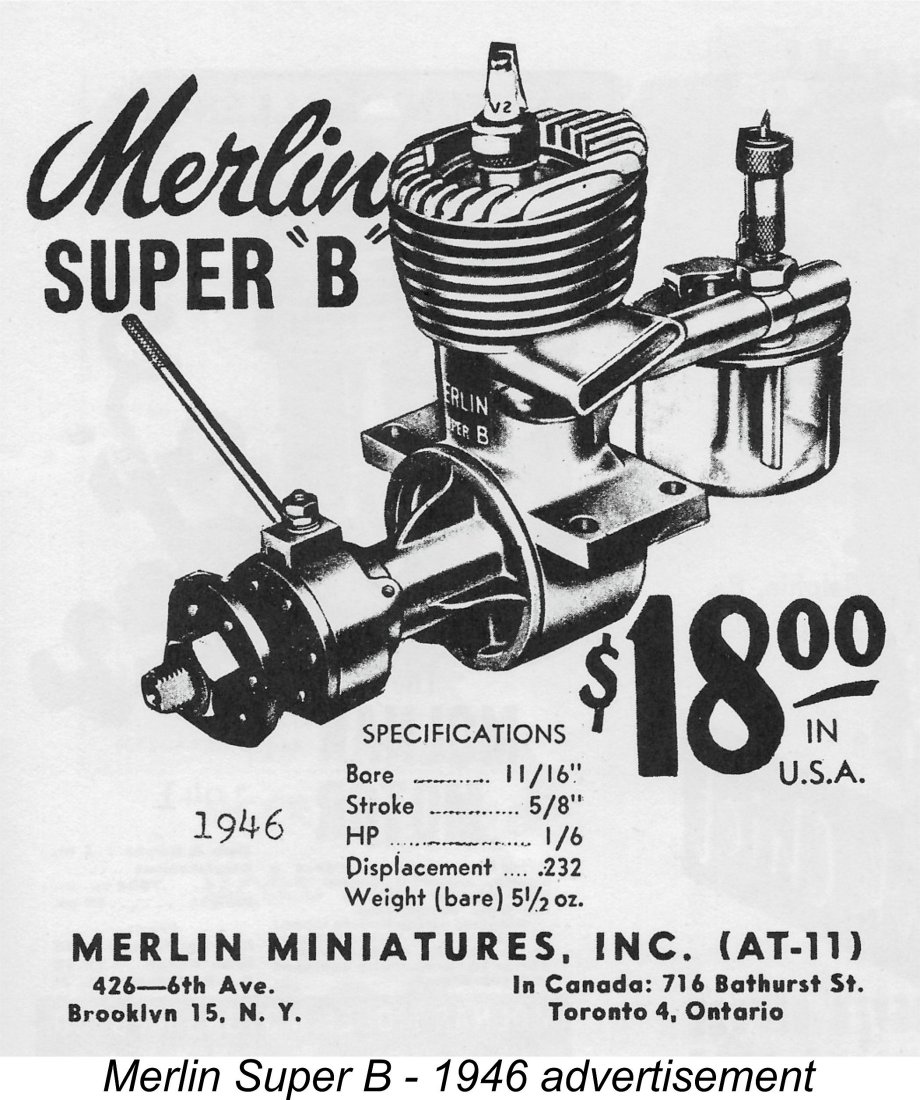
Among these new manufacturers was a firm called Canadian Hobbycraft of 716 Bathurst Street, Toronto 4, Ontario. This company’s flagship product was the 0.232 cuin. (3.80 cc) Merlin Super “B” spark ignition unit which forms the central subject of this article. The first advertisement for this engine appeared in the December 1944 issue of “Model Airplane News”. According to information supplied by knowledgeable long-time Toronto resident Dave Axler, the man behind the Merlin venture was an individual named Samuel Solomon Altbaum (1915 - 1958). It reflects sadly upon the attitudes prevailing at the time that he evidently encountered discrimination problems due to his combination of a Polish name with a Jewish ethnic background. This led him to change his name to Sammy Crystal, taking his mother's name from her second marriage. It was under that name that he embarked upon the Merlin venture at the age of 29. However, there's no evidence to suggest that he ever changed his name legally - it would appear that he retained his legal birth name lifelong, using the Crystal surname purely in a business context.
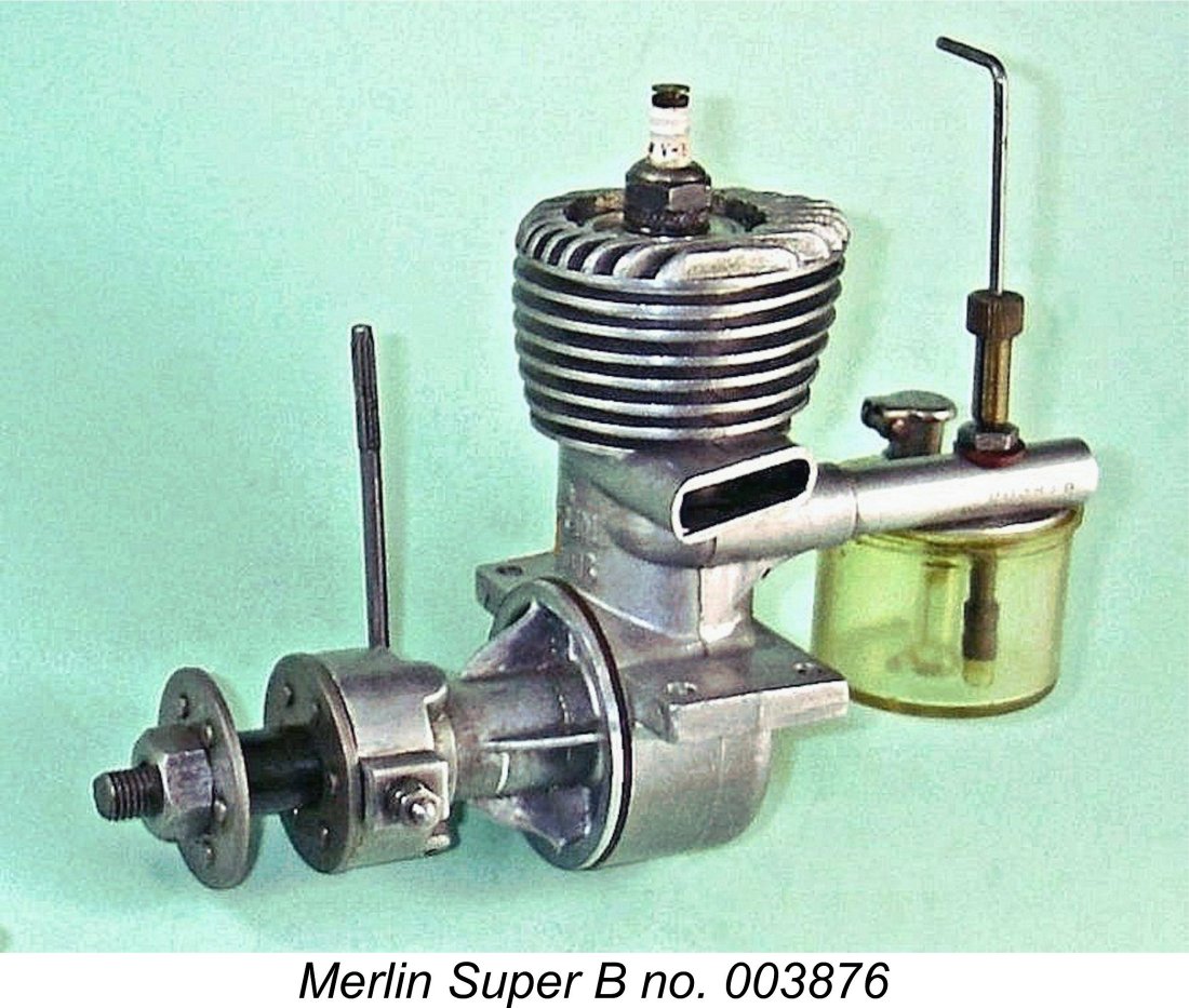
This advertisement is highly informative in several ways. It attributes the manufacture of the engine to a company called Canadian Hobbycraft located at 716 Bathurst Street in Toronto 4. This company name also appeared on the boxes in which the engines were supplied. Even more interestingly, the ad confirms that the distribution of the engine in the USA had already been assigned to a company called Model Aircraft Supply Co. located at 426 - 6th Avenue in Brooklyn 15, New York. Very quick work indeed! An amusing side observation is that the image of the engine which formed part of this advertisement was a "mirror image" with everything backwards. Oops .............! Let’s have a closer look at this intriguing unit …………. The Merlin Super “B” - Generic Description
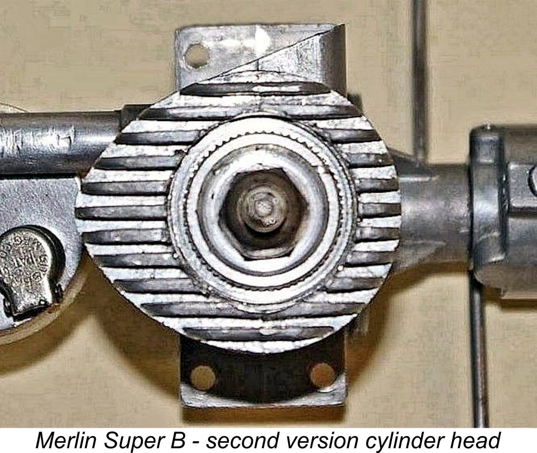
Despite its fundamentally conventional design, the Merlin did incorporate a number of interesting features in addition to its short stroke which set it apart from many of its contemporaries. It featured a crankcase, backplate, exhaust stack, finned cylinder barrel and head fins which were all cast in a single piece - in fact, it was one of the very first model engines to do so. This arrangement obviously necessitated the installation of the cylinder liner from the top.
Fair enough, but the earliest examples had heads which displayed no evidence whatsoever of the manner in which they were installed and tightened! Later versions had modifications which seemed to indicate the method of installation, but the way in which those first examples were assembled remains a matter for speculation. I’ll have more to say on this topic when I discuss the different variants of this motor. The cylinder barrel cooling fins were quite distinctive in being cast considerably deeper at the rear than at the front. Apart from the resulting "streamline" cylinder appearance, the practical effect was to provide additional air-cooling surface area at the rear, which didn’t receive as much slipstream-induced cooling airflow as the front. The same design approach was used by Ray Hunter on his famous Super Hurricane 24 FRV model, also from The Merlin’s cylinder porting was quite conventional, the one noteworthy feature being the placement of the induction port at the side beneath the exhaust port rather than at the rear in more typical fashion. This of course necessitated the use of an offset intake venturi. The advantage was that there was no possibiity of the gudgeon (wrist) pin fouling the induction port. According to Dave Axler, the pistons of the earliest Merlins were stamped. However, a switch was quickly made to a fully machined component Both the lapped baffle piston and the cylinder liner were made of steel. This can be a problematic combination unless great care is taken to get the initial fit just right. Both of my examples of the engine are perfectly fitted. The con-rod was a die-casting in aluminium alloy, with a bronze-bushed big end bearing. The rod drove a one-piece steel crankshaft having a counterbalanced crankweb. The shaft ran in a bronze-bushed main bearing.
Before we throw up our hands in horror at this seeming design oversight, we have to stop and think about the implications. What consequences would result from the front housing starting to unscrew during operation? Simply that both housing and timer would begin to rotate in the operating direction. This would have the effect of retarding the ignition timing. Before the housing rotated as little as 40 degrees, the engine would stop, with no damage done. In effect, the assembly embodied an unmistakable warning system that the front housing was coming loose and needed re-tightening! Regardless, please don’t add to the number of these engines displaying damaged webs by attempting removal using an incorrect tool! One of my examples displays evidence of this kind of abuse, and one’s quite enough! An appropriate tool is very easily made, if you really must take a look inside. If you have access to a lathe, a 4-jaw chuck also constitutes a very useable tool. The well-made timer was of conventional enclosed pattern. Two different timer control arrangements were used during the engine’s production life. These were based upon the same casting. In what appears to be the earlier of the two systems, the timer arm screwed directly into a raised boss at the rear of the timer, being retained by a locknut. The timer’s resistance to unwanted auto-rotation during operation was adjusted by a small screw which passed through a separate split raised boss to tension the clamp as required.
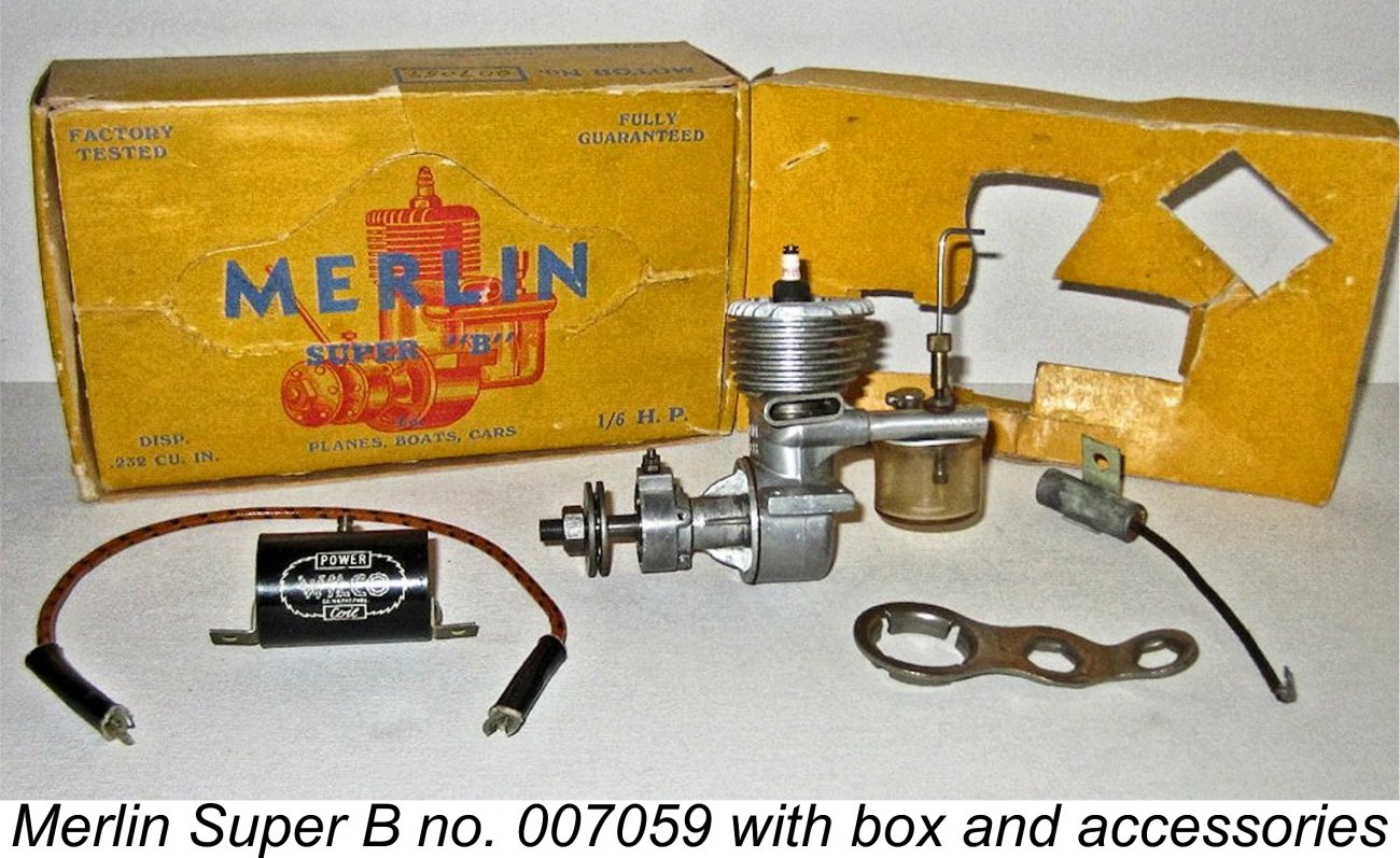
Oddly enough, these two timer styles appear more or less indiscriminately on engines covering the full range of known serial numbers. Whichever version was used, the timer was actuated by a cam formed integrally at the front of the crankshaft’s main journal. The assembly was completed by a steel prop driver which was keyed to the shaft using a single flat machined onto the prop installation spigot. This can be another problematic feature - prop drivers keyed in this way tend to develop a “wobble” quite rapidly in service. An interesting side observation is that the thread used to secure the prop was the standard ¼-32 used for plug installation - a very suitable thread, but one which was very seldom employed for prop mounting purposes. Don’t lose that prop nut! All of the Merlin engines were supplied with clear plastic hang-tanks having flat alloy tops with Gits filler caps. Two needle valve styles were successively used, with tension In general, the Merlin Super “B” was constructed to a very acceptable standard. The engines were sold in strikingly-decorated cardboard boxes complete with V2 spark plug, coil, condenser, high tension lead, special wrench and very comprehensive instructions. The earliest boxes displayed the notation “Made in Canada”, while the later box referred to the Brooklyn post box address through which the engines were then being marketed. More of that below. The Merlin appeared in three successive variants between late 1944 and late 1947, although these variants differed only in minor detail. They were manufactured in considerable numbers. There's no evidence that any attempt was ever made to develop a glow-plug version of the engine - the November 1947 appearance of the commercial miniature glow-plug appears to have triggered an almost immediate end to all production. Let’s now have a look at the three versions in which the engine appeared. The Merlin Super “B” - Variants
The designation “Made in Canada” was stamped onto the rear of the main crankcase. The serial numbers were initially stamped on the top of the right-hand mounting lug, beginning with the letter “A”. This implies that a “B” series was envisioned at some point, although the engine was identified on the front of the case as the Merlin Super B throughout. The obvious question as to why the prefix "B" was not adopted instead of the letter "A" is unresolvable.
The most interesting aspect of this original model was the fitting of the previously-illustrated cylinder head. This component was externally threaded around the rim and screwed into position on a female thread cut into the interior of the cast cylinder barrel. However, there’s no visible means of tightening or removing the head!
If all was well, the lock-nut would have been slackened off, still holding the engine stationary and using the head of the bolt to resist the resultant torque, thus preventing the unscrewing of the head. Once the lock-nut was slackened off, the bolt would turn freely and could be removed without disturbing anything. We don't know for sure that this was the method used, but it appears to me to be likely - I can't think of an alternative approach. Dave Axler recalled that on occasion the head would begin to unscrew when an attempt was made to remove a spark plug that had been installed too tightly. With such a design, we might expect this. If it happened, the only recourse would be to complete the unscrewing of the head and free the stubborn plug with the head out of the engine. It would be essential to hold the removed head in a way that avoided marring the peripheral thread while freeing the plug. Then one would have to break out the bolt and lock-nut combination to re-tighten the head. Apparently the earliest engines featured an asbestos gasket to seal the head/cylinder interface. Quite apart from its now-understood health implications, this is not a good idea in functional terms, as the manufacturer soon learned. Later engines used a soft copper sealing ring - a far more rational concept. Many if not all of the early engines also featured stamped steel pistons, although this design was soon switched to a fully machined component.
The second variant was basically similar, but the exhaust stack was considerably shorter, with its outer end now sharply angled towards the rear. Some examples were angled at 10 degrees (as seen at the left), while others were cut at 20 degrees (as seen below at the right). Interestingly enough, the marks on the end of this stack prove that the same casting was still being used - the shortening was clearly done using some kind of saw rather than being cast. It seems possible that many of the castings had flawed exhaust stacks due to incomplete filling of the die, leading to the stack being shortened to eliminate the flaw. It’s had to see any other reason for this added manufacturing step. A few of these models featured a revised cylinder head having two holes drilled partway through the head to provide purchase for a pin spanner. In addition, a few early examples of this variant retained the “Made in Canada” stamping on the lower rear face of the integrally- Reported examples marked in this way go up to engine number 2028, although they may well have gone higher - the available sample is not large. At that point, a few more changes were introduced, producing the third variant of the engine. The cylinder head was still a screw-in component, but now featured a large-diameter slightly raised boss having a series of small teeth formed around its edge. It would appear that a special socket wrench having a matching set of internally-formed teeth was used to tighten and remove this head. The designer still clearly wished to discourage tampering! It seems likely that the tool used for tightening was actually the die which cut the teeth in the head.
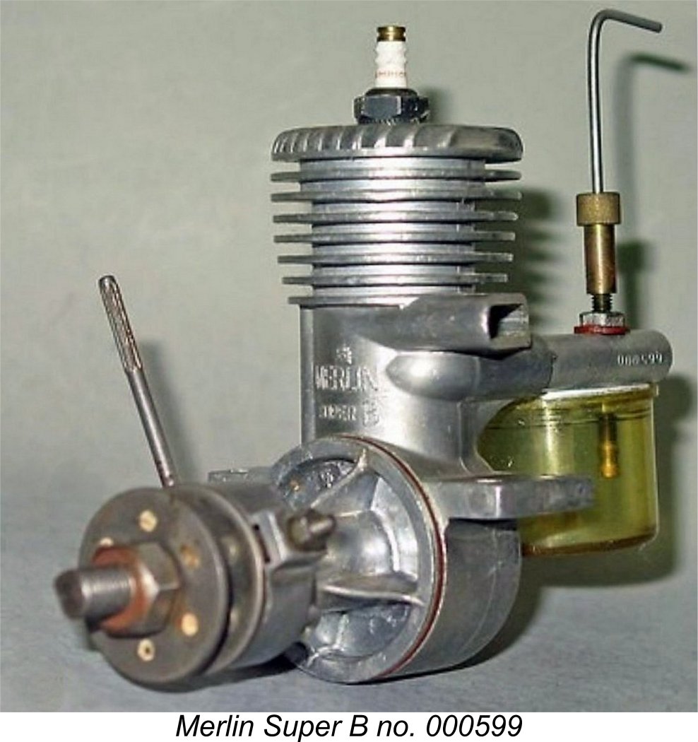
At this point the serial number sequence was restarted. The new serial numbers all had six digits beginning with the number 0, apparently starting from 000001. The range of such numbers which has so far come to my attention goes from 000599 all the way up to 010550, seemingly implying the manufacture of at least 10,550 examples in this series. These reported numbers establish a very clear overlap between the earlier examples with either an "A" prefix or no prefix at all. It would seem that at least 2028 examples of the early renditions were manufactured before the serial number sequence was restarted at 000001 and relocated to the intake tube. The two distinct numerical sequences are thus additive, suggesting that at least 12,500 examples of all models were produced in total. The Manufacturing Question There appears to be no doubt at all that the Merlin Super "B" was designed and originally manufactured in Canada starting in late 1944. The statement that the engines were made in Canada was repeated both on the engines and on the original boxes. The 1946 "Air Trails" review of the engine (see below) also stated that the engine was "originally manufactured in Canada". However, the initial advertisement of December 1944 included the After the later dropping of the “Made in Canada” designation from both the engines and the boxes, the substitute claim was made that the engines were “Made in USA” by a firm calling itself Merlin Miniatures, Inc. The address included with the engines was Box 33, Station V, Brooklyn 15, New York - no actual location was provided. However, the later advertising such as that reproduced at the right proves that this operation was conducted from the same address previously cited as that of the Model Aircraft Supply Co. at 426 - 6th Avenue in Brooklyn 15. Long-time Canadian resident Dave Axler recalled that Polk's Hobbies of New York had something to do with the marketing of the Merlin in the USA. He claimed that Sammy Crystal made several trips down to New York during the period 1946-48, presumably to discuss marketing issues. However, Polk's Hobbies never appeared in the advertising for the engine - the US address given all along was the Brooklyn location of the Model Aircraft Supply Co. It seems likely that Polk's involvement was confined to them being a major retailer of the engine. The claim that the manufacture of this engine was switched from Canada to Brooklyn has always appeared highly suspect to me. Mike Cook very much shared my suspicions. Apart from the claim (which is merely a few strokes of the artist’s pen), there’s no direct evidence whatsoever to confirm that any engines were actually manufactured in Brooklyn! In fact, logic rather argues against it. To begin with, the street address given in the later advertising was originally cited as being that of a model goods distributing house rather than a model engine manufacturer. This gives the impression that it was merely an “address of convenience”. The omission of the stamped “Made in Canada” inscription and the switch to “Made in USA” boxes by no means precludes the possibility that the later engines were still either constructed in Canada or assembled in the USA from Canadian-made components. After all, the dies and tooling were all created and deployed in Canada, hence having to be relocated to a new facility in Brooklyn to allow manufacture there. Why go to all that trouble and expense……….? The “Made in USA” claim may well have been justified by the partial or complete assembly of the engines in Brooklyn using parts still manufactured in Canada and shipped down to New York in bulk. That was Mike Cook’s suspicion, which I share.
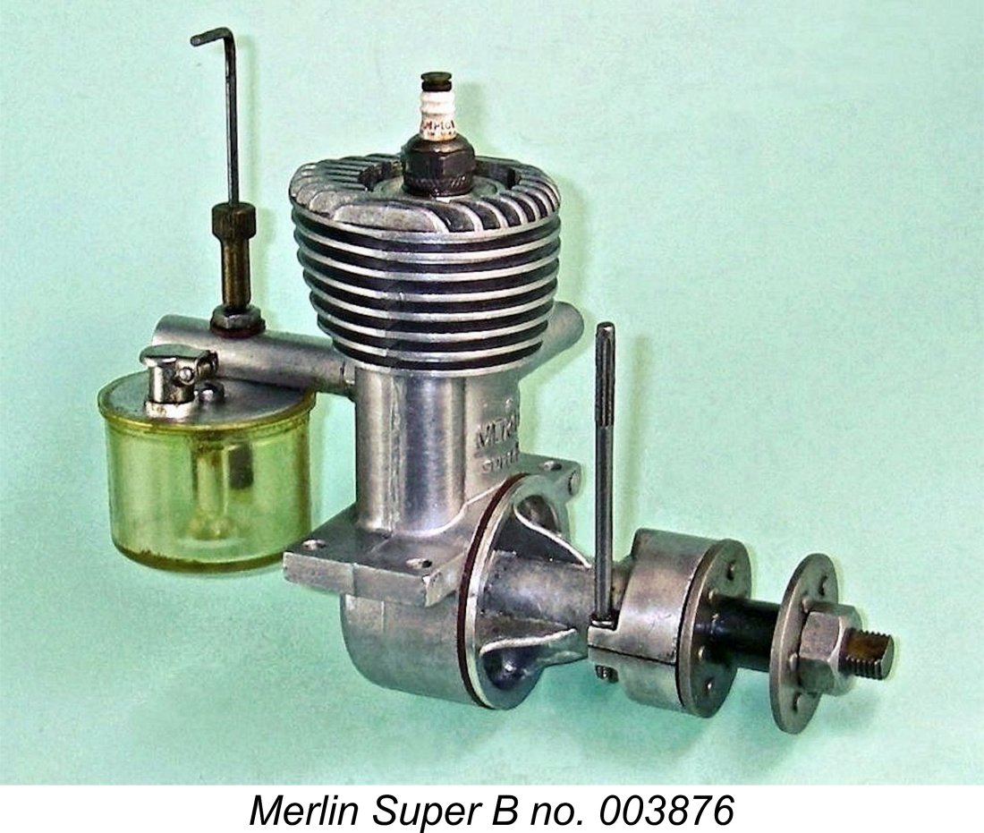
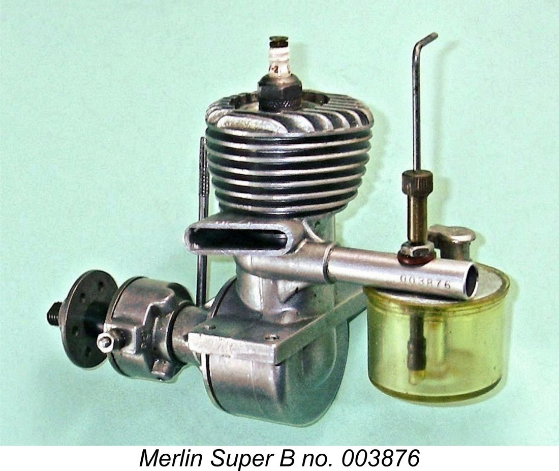
The notion that at least some of the engines continued to be manufactured in Canada all along is strongly supported by the fact that engine no. 007059 (a relatively late example) was sold in a matching-numbered “Made in Canada” box, albeit with no “Made in Canada” stamp on the engine itself, while earlier unit no. 003876 came in a quite different Brooklyn-labelled container featuring a "Merlin the Magician" image (see below at the right) instead of a representation of the engine itself (see image reproduced earlier). Unless manufacturing was still taking place in Canada, it's really difficult to see why two different boxes would have been used throughout, as they appear to have been. If some units were still manufactured in Canada, with or without crankcase stamps, why not all?!? The idea that the same engine would be manufactured in two locations simultaneously appears to me to be absurd. Further support for the engine’s ongoing Canadian origin comes from the fact that the Canadian address continued to receive equal billing in the advertising along with the Brooklyn location. All in all, the designation of responsibility to the Brooklyn-based concern looks to me like nothing more than a The impression gained from all of this is that the engines' components were made in Canada all along, as were some of the complete engines, but the "Made in Canada" stamping was eliminated and a different box was created in which to package engines sent down to the USA either complete or in component form to be distributed from the Brooklyn address. The "Made in U.S.A." claim which appeared on the Brooklyn-addressed boxes may well have been nothing more than a marketing ploy, possible justified by the engines being assembled in whole or in part at the Brooklyn location using components manufactured in Canada. OK, so now we know a little about this engine’s history and main structural features. Next question - how does it run? Only one way to find out - break out the test stand! The Merlin Super “B” on Test
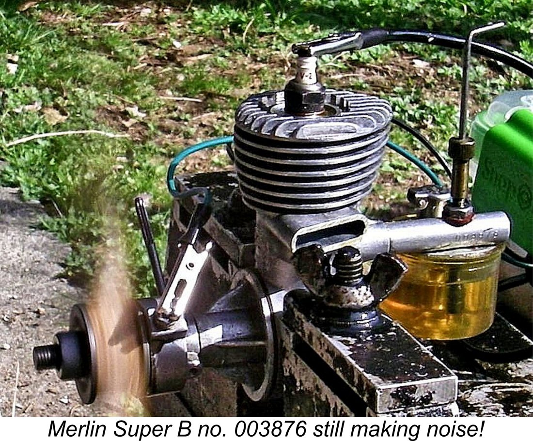
Unfortunately, the test reports published in “Air Trails” at the time fell well short of constituting what we would generally think of as a comprehensive test. The report included some useful information regarding the engine’s structure and its material specification, but no torque or horsepower figures were provided. The only performance data was a claim that the test engine would turn a ”standard” 9 inch diameter high pitch prop (whatever that was!) at 9,300 rpm and a “standard” 10 inch diameter high pitch prop at 7,200 rpm. The actual pitches were not specified. The “Air Trails” report included a highly informative cutaway drawing of the engine. This drawing was interesting insofar as it clearly showed a twin-ringed aluminium alloy piston despite the text’s statement that a hardened steel piston was featured! To my knowledge, no ringed piston example of this engine has ever turned up. It was clear that in order to get some idea of the Merlin’s actual performance, I would have to conduct my own test. For this purpose I initially chose an almost new complete and original example of the second version of the engine. This example still retains its box bearing the Brooklyn post box address and appears to be little if at all used. It carries the serial number 003876 and sports the standard plastic tank.
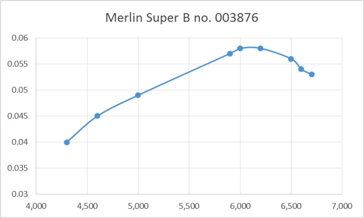
The sparks were supplied by one of my containerized Larry Davidson spark ignition support systems, which I have found to be completely dependable in service. The fuel was my usual sparkie blend of 75% Coleman camp fuel (white gas) and 25% SAE 60 mineral oil (AeroShell 120). I used the standard plastic hang-tank for all testing. Setting the timer to open the points about ten degrees before top dead centre, I got down to it. Getting the engine firing initially required the administration of a small exhaust prime. This was probably down to the presence of a fair amount of storage oil which needed to Once the Merlin was running, it proved to be a very easy matter to establish both the optimal ignition timing and the best needle valve setting. The engine proved to be an excellent runner, performing very smoothly with no tendency to sag and quite acceptable levels of vibration. It seemed to be perfectly happy on the 10x4 test prop. In deference to the fact that this example appeared to have very little running time to its credit, I ran four or five tankfuls through it at a slightly rich and retarded setting, just to ensure that things were well settled. The exhaust remained very clear throughout, with little smoke and no evidence of rapid wear on any component. After this period of shake-down running, I found that the Merlin was turning the 10x4 Rev-Up wood prop at a steady 5,900 rpm when correctly set. Since I was hoping that the engine would do a little better than this, I proceeded to try a few lighter loads. Unfortunately, it transpired that the engine was operating very near to its peak on the 10x4 - it just didn’t seem to want to run much past 6,500 rpm under any load. A few checks of some heavier loads confirmed that it preferred to run at somewhat lower speeds. In the end, the following data were obtained.
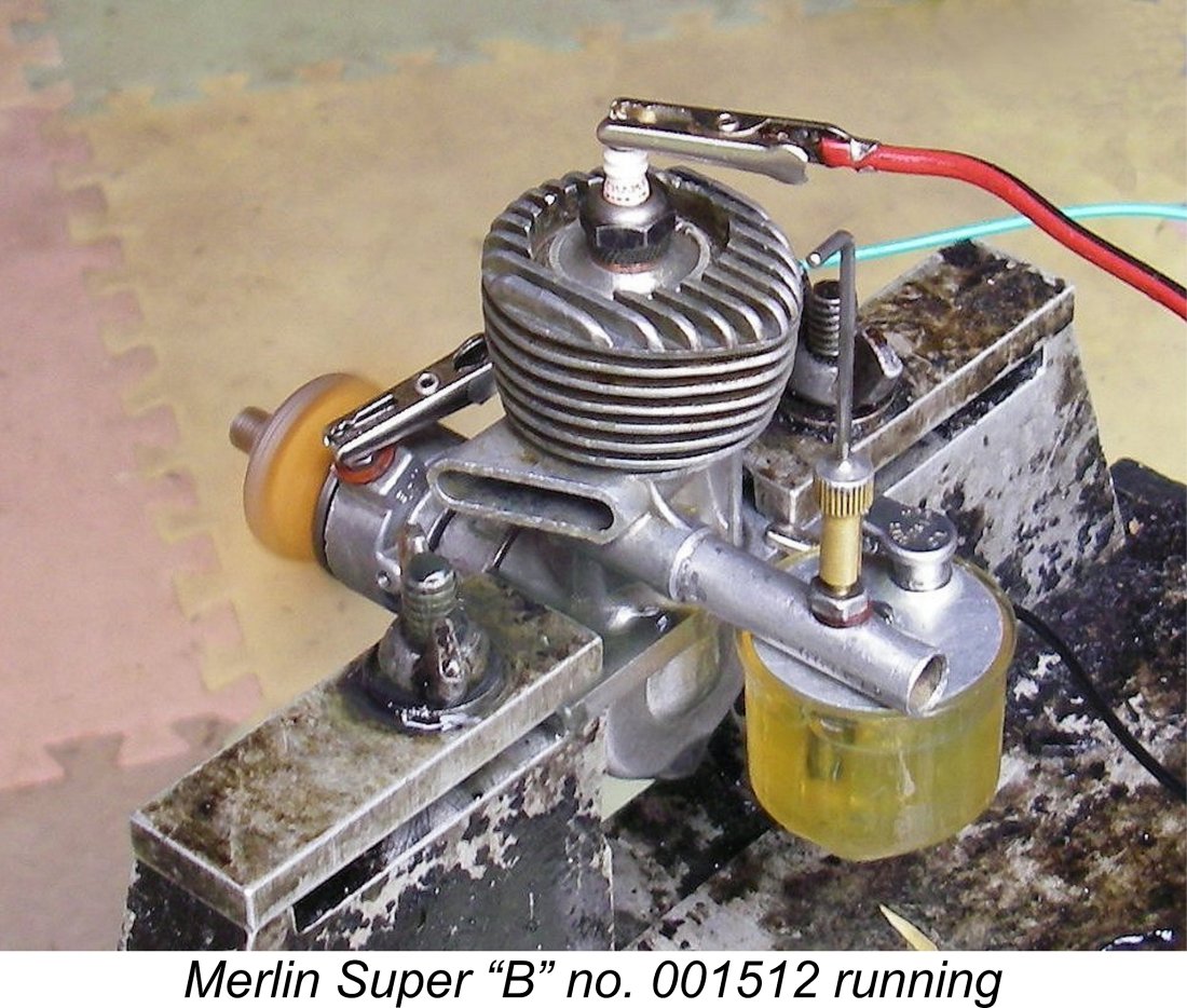
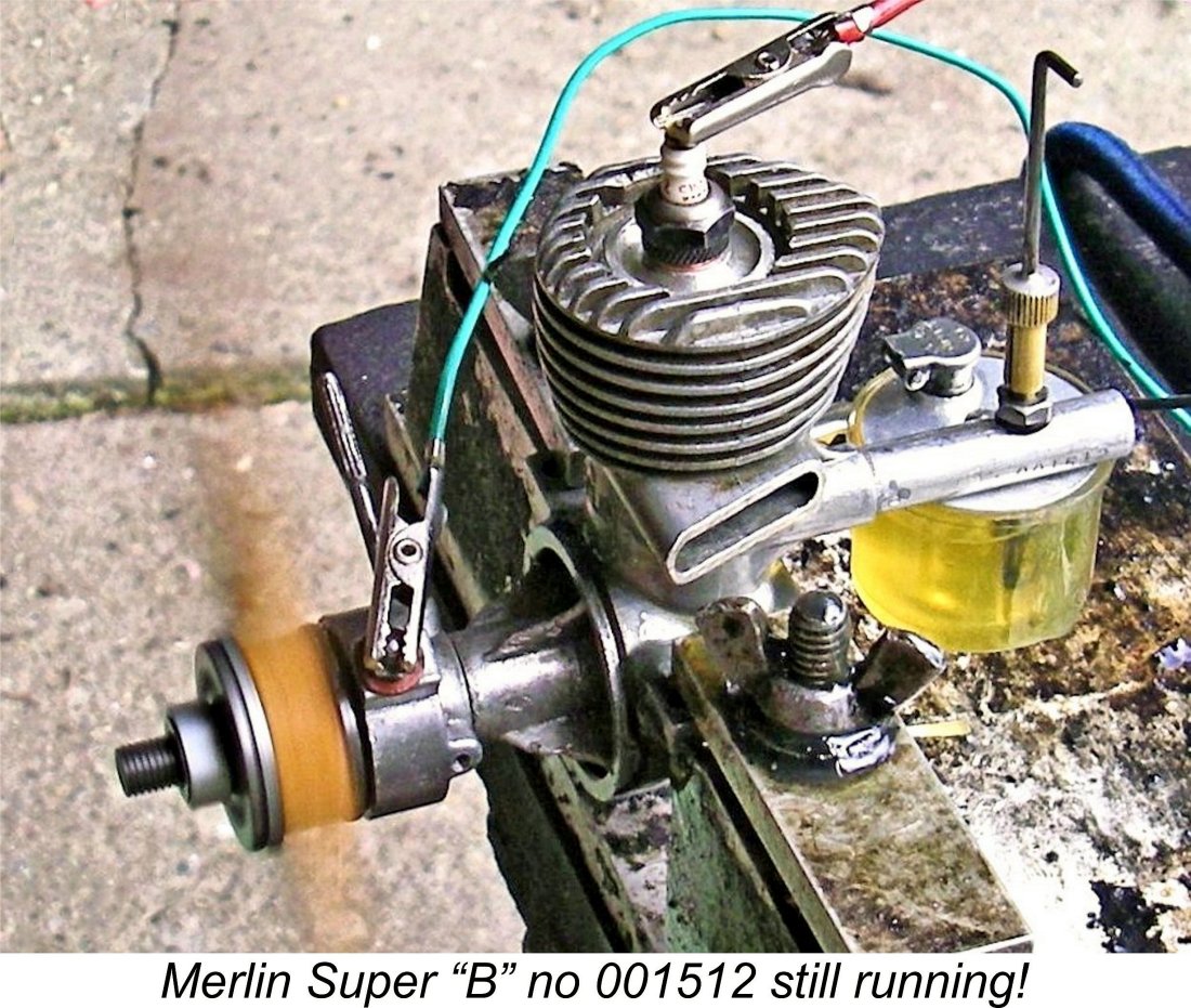
These res Moreover, my findings fell way short of matching the output of 1/6 HP (0.166 BHP) claimed on the box label! My tested example appeared to develop a peak output of 0.058 BHP @ 6,100 rpm. It’s in perfect mechanical condition, so I couldn't see it being a notably inferior performer to any other example. It started and ran very well indeed - it was simply not developing a lot of power! Fortuitously enough, I had a second example of the Merlin available for testing. This one had clearly seen a considerable amount of use, although it remained in complete and original condition. It bore the serial number 001512 stamped on the intake.
I began with the 10x4 Rev-Up prop fitted, since this had allowed the previously-tested example to run at very near its peaking speed on the bench. Engine no. 001512 proved every bit as easy to start and adjust as its companion no. 003876 tested previously. Once set, it ran perfectly without missing a beat. It was immediately obvious that this example was going to outperform its opposite number by a very considerable margin. The engine turned the 10x4 Rev-Up prop at a smooth and steady 6,900 RPM, a full 1,000 RPM faster than its predecessor. Trying the engine with the other test props featured in the previous test reinforced this initial impression. The following data were recorded.
It's interesting to note that the shape of the power curve is an almost exact duplicate of that recorded for engine no. 003876. However, everything is shifted around 1,000 RPM higher, with a consequent considerable increase in output. This example appears to develop around 0.092 BHP @ 7,000 RPM. Beyond that point, output falls off significantly - the engine appeared to be reluctant to run much faster than 7,500 RPM on any prop.
I have no explanation for the greatly inferior performance of engine no. 003876 - I've inspected it seven ways to Sunday and can find no apparent issues which could affect performance. It's undeniably somewhat stiffer than its very "experienced" relative, but I wouldn't have expected this much of a performance differential on that basis alone. Even so, the implication is that a good example of the Merlin Super "B" might develop as much as 0.100 BHP @ 7,500 RPM, but almost certainly no more. These findings offer a good deal of support for Mike Cook's recollection that as time went on the Merlin became widely viewed as something of a "gutless wonder" back in the day, disappointing many of its owners who were expecting more. Against that, Mike also retained a recollection that Sammy Crystal used an early example of the engine in a Megow Ranger and won almost every contest that he entered! In Mike’s recollection, that particular Merlin performed like a 29!! Perhaps Sammy had tweaked it in some way …………… also, it was 1944/45, when the opposition was somewhat less developed! While my findings imply a pretty unimpressive output for a 3.8 cc powerplant, it must be remembered that this design dates back to 1944, when power expectations for basic sports motors like this one were far more modest than they were soon to become. In the context of its time and place, the Merlin had a lot going for it despite the relatively low output - it was a well-made and notably lightweight engine which handled extremely well and ran very smoothly and controllably, also having plenty of power to fly a model. In the sport free flight models of the early post-WW2 period, it would have given full satisfaction to owners who weren't expecting leading-edge performance figures. Conclusion Although the Merlin Super “B” ended up being marketed and possibly manufactured in New York, it may legitimately be claimed as a Canadian design. I suspect that the establishment of a marketing base in New York was a reflection of a desire to tap into the vastly larger US market. It’s likely that American modellers of the day would have been far more inclined to buy an American product than a Canadian one. If this was the strategy, it seems to have worked! We appear to have evidence for perhaps as many as 12,500 examples of the Merlin (and possibly more) being sold over the engine’s approximately 3 year production life. The vast majority of these would have been sold in the USA - Canadian Hobbycraft could never have sold anything approaching 12,500 engines in Canada during the mid 1940’s. So chalk this one up as a Canadian success story! I only wish that I could have found out a bit more about the elusive Sammy Crystal and the various companies with which he was associated! _______________________________ Article © Adrian C. Duncan, Coquitlam, British Columbia, Canada First published June 2025 |
||
 Here I’ll present a review and test of a fairly well-known 0.23 cuin. (3.8 cc) spark ignition engine from the early post-WW2 era - the Merlin Super “B”. This engine is of particular interest to me insofar as it had its origins in my present-day home country of Canada, although it ended up being marketed and possibly manufactured in New York, USA.
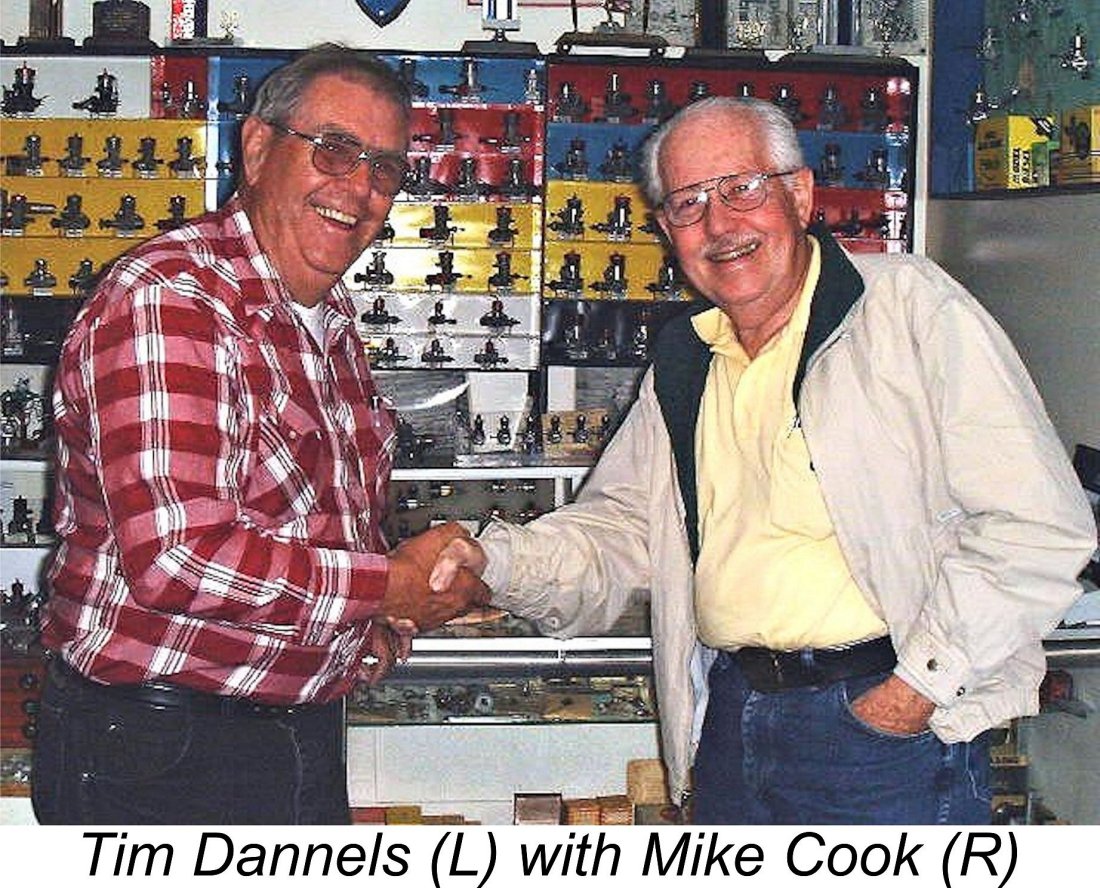

 Beginning with a few vital statistics, the Merlin Super “B” was a basically conventional sideport spark ignition engine of its era. A little uncharacteristically for a sideport sparkie, it was a notably short-stroke design. Bore and stroke were 11/16 in. (17.46 mm) and 5/8 in. (15.87 mm) respectively for a bore/stroke ratio of 1.1 to 1 and a calculated displacement of 0.232 cuin. (3.802 cc). The engine weighed a commendably light 162 gm (5.72 ounces) all complete with timer, tank and plug.
 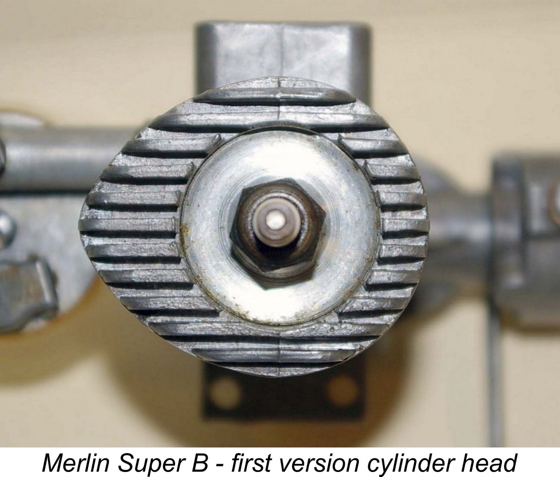 Straightforward enough, but the design of the cylinder head which sealed the bore was highly unusual. No screws were used to tighten things down - instead, the externally-threaded head engaged with a female thread formed inside the cylinder barrel above the cylinder installation bore.
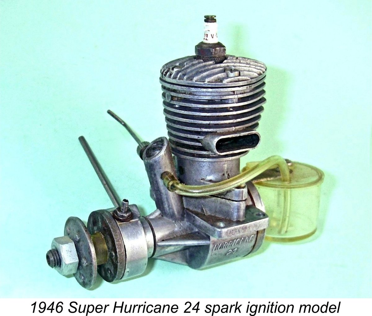
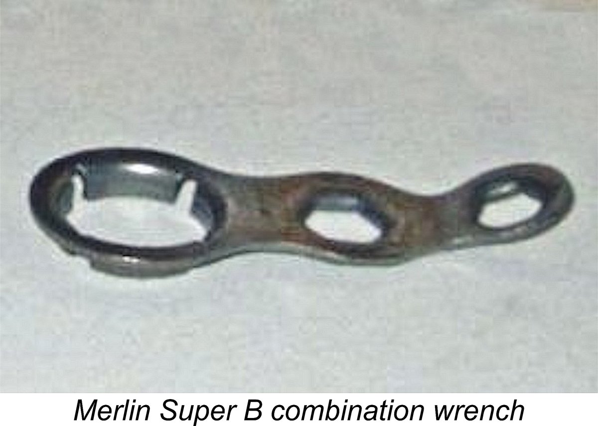 The main bearing housing was a screw-in affair which was tightened using a special tool having grooves cut into it in an X-alignment to match the four main bearing bracing webs. Such a tool was provided with the engine, also incorporating plug and prop nut sockets in combination. Logic says that the bearing ought to be installed using a left-hand thread to prevent unscrewing during operation in the “normal” direction. However, the fortuitous fact that the front cover on one of my examples came loose while I was fiddling with the timer clamp tension revealed that it is actually a right-hand thread.
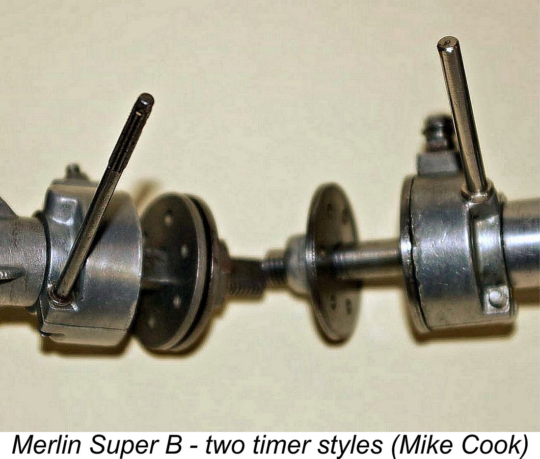
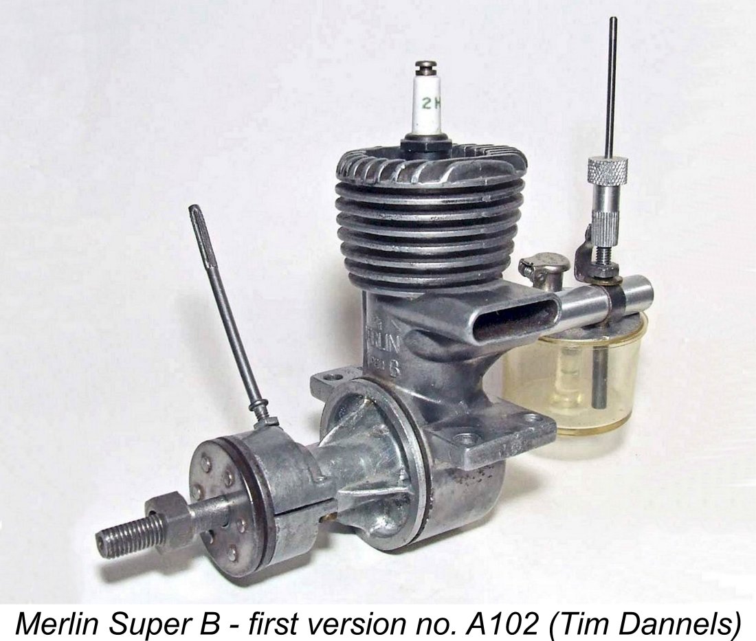 The Merlin Super “B” was made in Toronto, Canada by Canadian Hobbycraft, at least at the outset. It seems fairly safe to assume that the designer was Sammy Crystal.
 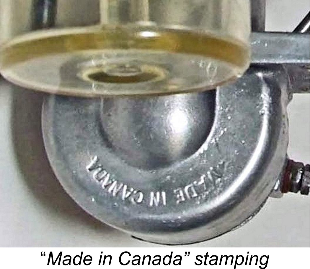 The exhaust stack of this first model had an outer end which was parallel to the engine’s main axis. The venturi tube accommodated a wrap-around sheet metal clamp which incorporated the needle tensioning clicker. Examples of this variant generally featured the earlier timer design discussed previously.
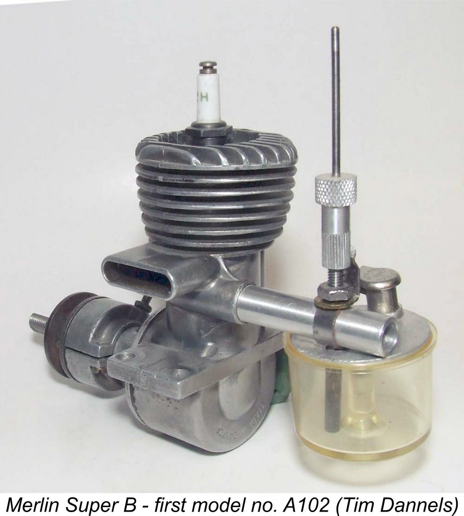 I believe that the approach was most likely to tighten the head by inserting a suitably-threaded bolt into the plug installation hole and securing it with a lock-nut. The lock-nut would then provide the purchase for tightening the head with the engine held firmly in some kind of clamping system to keep it stationary against the torque. Once this was done, the head would be pressure-tested for leaks.
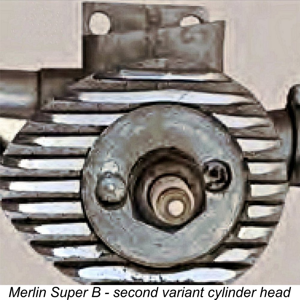
 The Merlin Super “B” was the subject of a review which appeared in “Air Trails” magazine during 1946. It was the fourth test to appear in the series published by this magazine. I don’t have the actual date - can any reader enlighted me? A scan of this test is attached for information.
 Anyone who has read my in-depth article on
 Deciding that there would be value in running the same set of test props on this second example to reinforce my earlier findings, I set this one up in the test stand. I used the same fuel as in the previous test, also using the engine's standard plastic hang tank and Champion V-2 spark plug. The sparks were supplied as usual by one of my
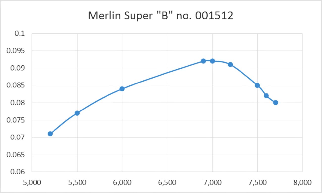
 The results of these two tests provide a high level of support for the notion that there's always value in testing more than one example of the same commercially-produced model engine. If I hadn't tested the second example, I would have been reporting performance figures for the Merlin Super "B" that fell far short of its true potential.
 | |