
|
|
The MVVS 2.5R-58 - an Outstanding Classic Racing Engine on Test
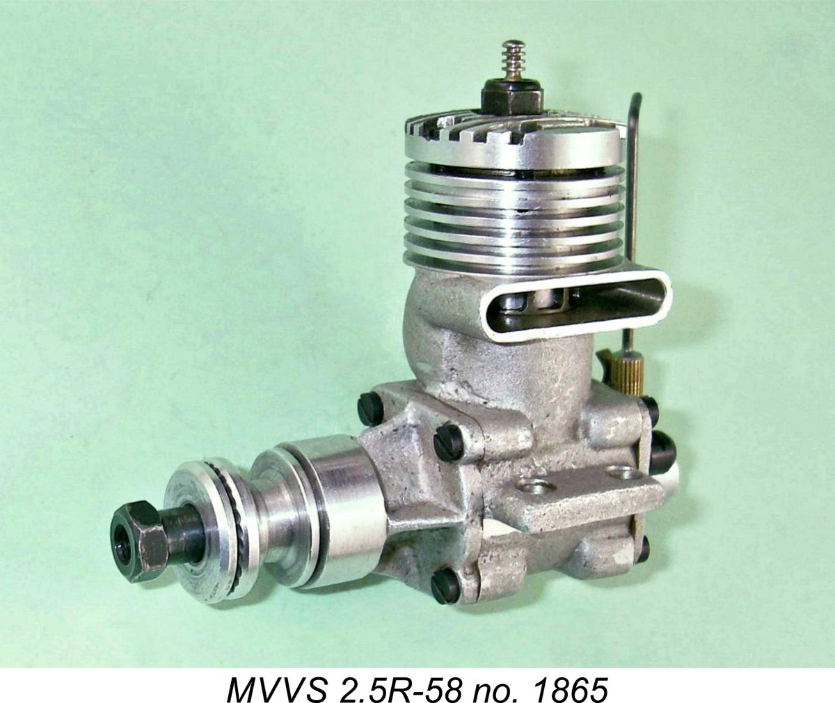
Although it covered the history of these remarkable engines in some detail and also reported on Peter Chinn’s test of an example of the MVVS 2.5R-58 (“Model Aircraft”, November 1960), the earlier article did not include any latter-day test figures. This has always been a matter of some interest given the fact that Chinn tested that particular engine in a configuration which was not as intended by the engine’s designers. It's worth mentioning for the record that the "Model Aircraft" test engine was incorrectly identified by Peter Chinn as the MVVS 2.5/1959. In reality, that designation was applied to a limited edition "works special" variant of the engine which had (among other improvements) a needle roller big end bearing. An output of 0.47 BHP @ 19,500 rpm was claimed by the factory for this model, of which only a few examples were made for the exclusive use of the official MVVS works team members. The engine tested by Chinn was unquestionably a standard example of the MVVS 2.5R-58 variant having a plain big end bearing. Chinn's test example had its exhaust stack conventionally oriented to the righ Well, to answer that question we have to take a very long hard look at the gas flow implications of the Dooling-style “bulge bypass” system which was utilized in the design of this engine. This analysis formed part of my earlier MEN article, but I’ll repeat it here for convenience. As most readers will be aware, the Dooling transfer system employs a hemispherical cavity on the transfer side which serves as the bypass passage. This cavity has no direct communication with the lower crankcase, thus possessing the advantage of minimizing crankcase volume and hence improving the engine’s base compression ratio and pumping efficiency. However, the absence of direct communication with the lower crankcase means that an alternative pathway has to be provided for fuel mixture to enter the bypass cavity. This requirement is met through the provision of large ports in the piston skirt which correspond to similar ports in the cylinder liner at and around bottom dead centre. These liner ports are in turn aligned with the lower portion of the bypass cavity. This arrangement ensures excellent communication between the crankcase interior and the bypass passage at all times when the transfer ports are open. However, it necessarily results in a piston from which much of the skirt on the transfer side has to be removed. In the case of the MVVS engines (and their 5 cc Vltavan derivatives, of which more elsewhere), these skirt ports were very large indeed, eliminating even more of the piston skirt than usual on the transfer side, to the point where there was virtually no skirt left! Now with the exhaust stack located on the right in the conventional manner, the side-load during the power stroke would all be directed to the transfer side of the piston. However, this side of the piston in a Dooling set-up is extremely poorly equipped to deal with these loads - there simply isn’t much of it left! Not a good situation either for mechanical reliability or engine longevity.
So there were compelling mechanical arguments in favour of a left-side location of the exhaust stack. But what about the potential effect upon transfer efficiency?? If such a relocation of the exhaust stack would have compromised engine performance in any way, there’s no possibility that the MVVS designers would have adopted it – they would have accepted that the price to be paid for improved mechanical integrity was simply too high in performance terms. In the World Championship control line speed context in which they were designing the engine, ultimate performance was the imperative rather than longevity. So the performance implications of making this change must surely have been well considered by the MVVS design team. Here another consideration entered the picture - that of crankcase swirl. The gas in the crankcase of a two-stroke engine does not sit still – it swirls quite strongly in the direction of rotation of the shaft. At the speeds at which racing glow-plug engines were even then operating, this swirl effect was quite considerable. Speed engine designers were beginning to appreciate the potential benefits of this, hence planning their engines to take maximum advantage of crankcase swirl during the transfer process. Naturally the swirl imparted considerable velocity and hence kinetic energy to the mixture in the case. Designers realized that this energy could be harnessed to help move the gas into the bypass passages and up through the transfer ports more rapidly if those passages were appropriately placed and configured. In effect, the crankcase was being seen as a kind of centrifugal pump which could assist in the transfer process (remember, this was before the advent of tuned pipes!).
So the conventional orientation of the cylinder works fine with the typical vertical bypass passage opening directly off the crankcase in the normal manner for loop-scavenged motors. But in the case of a Dooling set-up, the mixture enters the bypass more horizontally than vertically, crossing just below the piston crown in order to do so (and thereby contributing very significantly to the cooling of the piston crown). If you think about the swirl effect for a Clearly, the MVVS designers thought this through very carefully and concluded that the location of the exhaust stack on the left side of the engine was both mechanically desirable and more efficient in term of the gas transfer from the case to the cylinder. Decision taken …………photographs of Josef Sladký’s winning prototype example of this engine at the 1957 World Control Line Speed Championship clearly show that this stack orientation was undoubtedly applied to the all-conquering Czech team engines, also being carried over to their later series production models. The similarly-designed bulge bypass MOKI S-1 from Hungary which took the first two places in the 1958 championship was identically oriented. It's worth noting in passing that when I was researching my earlier article on the Dooling 61, I encountered several discussion threads in which a number of old-timers stated categorically that most serious users of the Dooling 61 switched their exhaust stacks to the left purely on account of the resulting improvement in performance. A couple of individuals claimed that the Dooling Brothers were well aware of this, to the point that they would supply new engines engines in that configuration. One individual actually recalled a long-ago conversation with Tom Dooling in which Tom explained the improved performance resulting from this stack orientation. I was fascinated to read that Tom's explanation was almost identical to that summarized above which I had previously developed independently as a result of my long direct acquaintance with these engines. But that's only part of the story when we're discussing the MVVS 2.5R-58 - what about the implications for the incoming charge of mixture which was to be transferred during the next cycle? Well, if one thinks about the fact that we want the cool fresh gas to enter the case, be picked up by the crank-induced swirl, cool the piston and arrive at the entry to the bypass at just the right time, we may gain some insight into the reasons why MVVS located the intake in the rather strange orientation that can be seen in the photographs, with the actual point of gas entry at the bottom of the backplate and the venturi angled to the right (viewed from the rear). If you mentally follow the swirl with the Dooling-type transfer set-up on th This might be expected to minimize the residence time in the crankcase of a given incoming charge of mixture - good for internal cooling, which is actually far more important than external cooling for a high-performance two-stroke engine. Not only that, but the rather odd orientation of the intake venturi itself (angled to the right) would impart a tangential component to the velocity of the incoming gas charge in the direction of swirl, thus minimizing any disruption of the swirl effect as the fresh charge entered the case. Job done ……….. Based upon the above line of reasoning, I have always had little doubt that the orientation of the case with the exhaust on the left was an intentional and well thought-out element of the design. Moreover, the unusual location and orientation of the intake were clearly intended to maximise the engine’s efficiency in moving the fuel mixture from the point of entry into the right-hand bypass, cooling the piston along the way. In effect, MVVS were trying to maximize the contribution of crankcase swirl to the overall pumping efficiency of the engine, as well as trying to promote improved piston cooling. They were also enhancing the engine’s mechanical integrity. The examples of the MVVS 2.5R-58 not infrequently encountered today with stacks on the right (and occasionally with the backplates incorrectly positioned) are almost certainly the result of interference on the part of owners who have failed to appreciate the designer’s intentions. Unfortunately, the engine tested by Peter Chinn was one of these incorrectly assembled units, thus failing to derive the benefit of the engine's carefully thought-out design features discussed above.
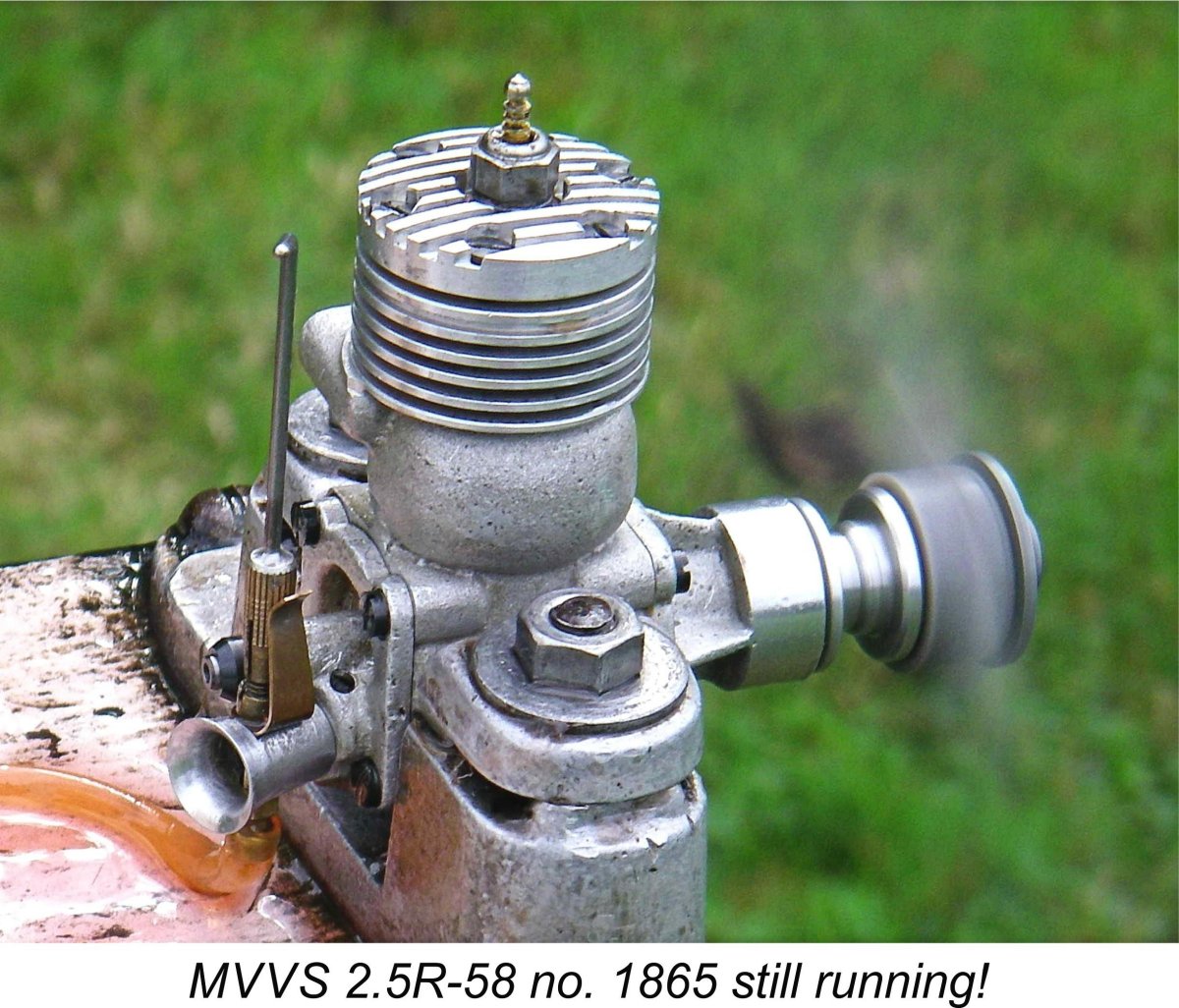
Johnny's example turned out to have been assembled from a mis-matched combination of MVVS and Vltavan parts with what appeared to be a home-made cylinder head, consequently delivering a somewhat sub-standard performance. However, the results of this test on my own engine were so remarkable that I thought them well worthy of being recorded here. The MVVS 2.5R-58 was expressly designed to be operated on a fuel having a very high nitromethane content. The performance figures quoted by the factory all referred to nitro contents of around 45%, with an added proportion of nitro-benzene. I wasn’t prepared to go that far - apart from anything else, nitro-benzene is a powerful carcinogen. Instead, I provided myself with a batch of fuel containing 30% nitromethane with a 28% castor oil content to preserve the engine during what promised to be a rather strenuous test. I’d run my tested example of the engine (serial number 1865) before, finding it to be very well broken in and all ready for hard work. Although it does not appear to have ever been mounted in a model, it has clearly Following a hefty port prime and a "bump" turn, the engine instantly earned my respect by starting literally on the first flick, a characteristic to which it adhered throughout the tests. A wide-open needle was required to establish a rich setting, but the needle valve assembly allowed for the establishment and retention of very precise mixture settings. Running qualities were outstanding – smooth as you like, with no trace of misfiring and no tendency whatsoever to sag. Vibration levels too were minimal, no doubt due to the very light piston which results from the use of piston rings on an alloy component (the entire rod/gudgeon pin/piston assembly weights only 5 gm) along with a suitably counterbalanced crankweb. The seal provided by the beautifully-fitted rings would have done credit to any lapped-piston diesel of my acquaintance. Before getting started, I had made the decision to limit the speeds achieved in this test to a maximum of 20,000 rpm – no sense in beating this old warrior to death! This turned out to have been a quite appropriate test limit. The engine’s fine handling and running qualities made this test a genuine pleasure. The following prop-rpm figures and implied BHP figures were recorded:
I will freely admit to having been knocked sideways by these results! In fact, they were so surprising that I actually went back and repeated the test, with almost identical results. I had been intending to include an APC 7x3, but since this would obviously have exceeded my self-imposed 20,000 rpm limit, I refrained. In any case, the associated power curve shows clearly that the props which were tested neatly bracketed the power peak. There is clearly a gap in my test prop series which might have hit the peak, but even so the above figures imply a peak output of around 0.470 BHP @ 18,500 rpm, with a notably flat peak - the engine appears to be exceeding 0.46 BHP at all speeds between 17,000 and 20,000 rpm. The power absorption coefficients for the specific APC props which were used to derive the output numbers are very well established through a long series of tests undertaken by myself and others.
While coming nowhere near the latter claim, the figures measured during these tests for my own engine actually exceed the factory claim for the 1957 “works” engines. They even match the claimed output for the improved 2.5R-59 model with its needle roller big end bearing. Admittedly the test engine is one of the 2000 or so numbered examples manufactured on a commercial basis in limited numbers beginning in the latter part of 1959. Hence it may incorporate some of the design So there we have it! In summary, these results obtained using what must surely be a rather exceptional example of the MVVS 2.5R-58 undoubtedly support the credibility of what have appeared in the past (to myself among others) to be somewhat exaggerated performance claims made by the MVVS factory. More to the point, they amply support the previously-discussed notion that this engine needs to be assembled in the correct orientation in order to give of its best. This being the case, there seems to be little doubt that Peter Chinn would have extracted significantly higher levels of performance from his test example if it had been correctly assembled. A truly wonderful engine in all respects! ________________________ Article © Adrian C. Duncan, Coquitlam, British Columbia, Canada First published October 2015
|
||
 Some of my long-time readers may recall a detailed article which I wrote some years ago on the subject of the classic 1950’s
  t (looking forward in the direction of flight) rather than to the left as originally designed.
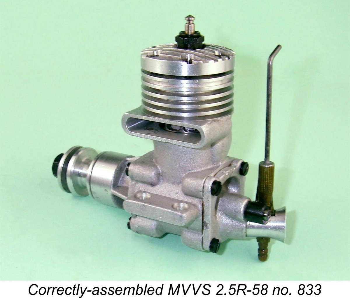 However, there was an obvious fix – switch things around so that the exhaust stack was on the left (viewed from the rear). If this were done, the power stroke side-thrust would be taken by the unbroken side of the piston skirt. The almost non-existent transfer side would only have to deal with the far smaller loads involved in the compression stroke.
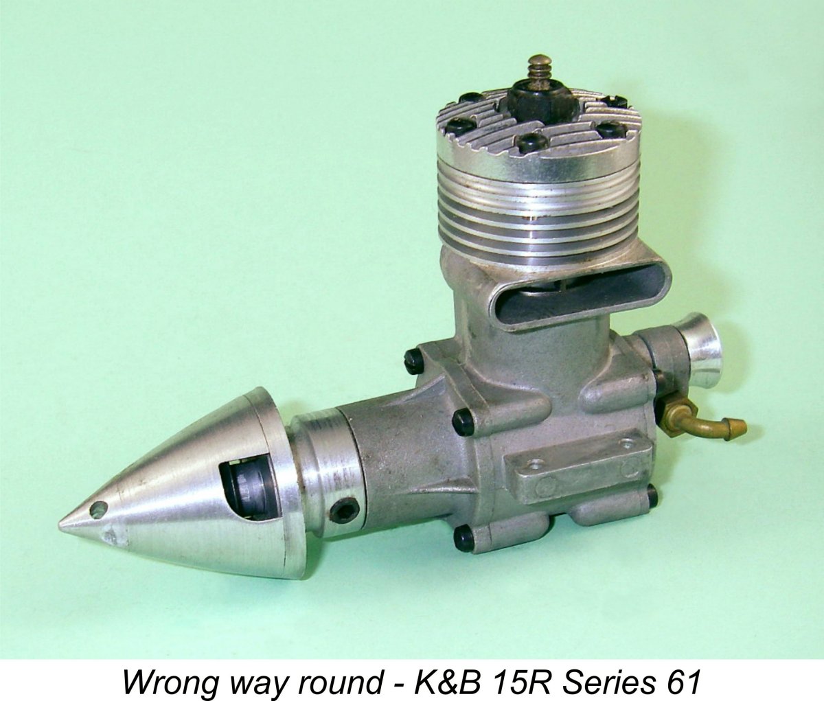 Now in the case of a conventional cross-flow loop-scavenged engine in which the base of the vertical bypass is open to the crankcase, considerations of the swirl effect would seem to indicate that locating the bypass on the left (and hence the exhaust on the right) should take maximum advantage of the swirl effect in an engine having the normal direction of rotation. The fresh charge of mixture will swirl with the spinning crank and head tangentially straight up the bypass in a vertical direction. In fact, one of the first things that every serious user of the K&B Series 61 and Series 64 racing engines did before even running them was to switch the case around to bring the exhaust stack to the right (I know, because I was one of those users!). The left-hand stack location was K&B’s trademark “house style”, but the right-hand location worked measurably better in practise at higher speeds, for the reasons stated above.
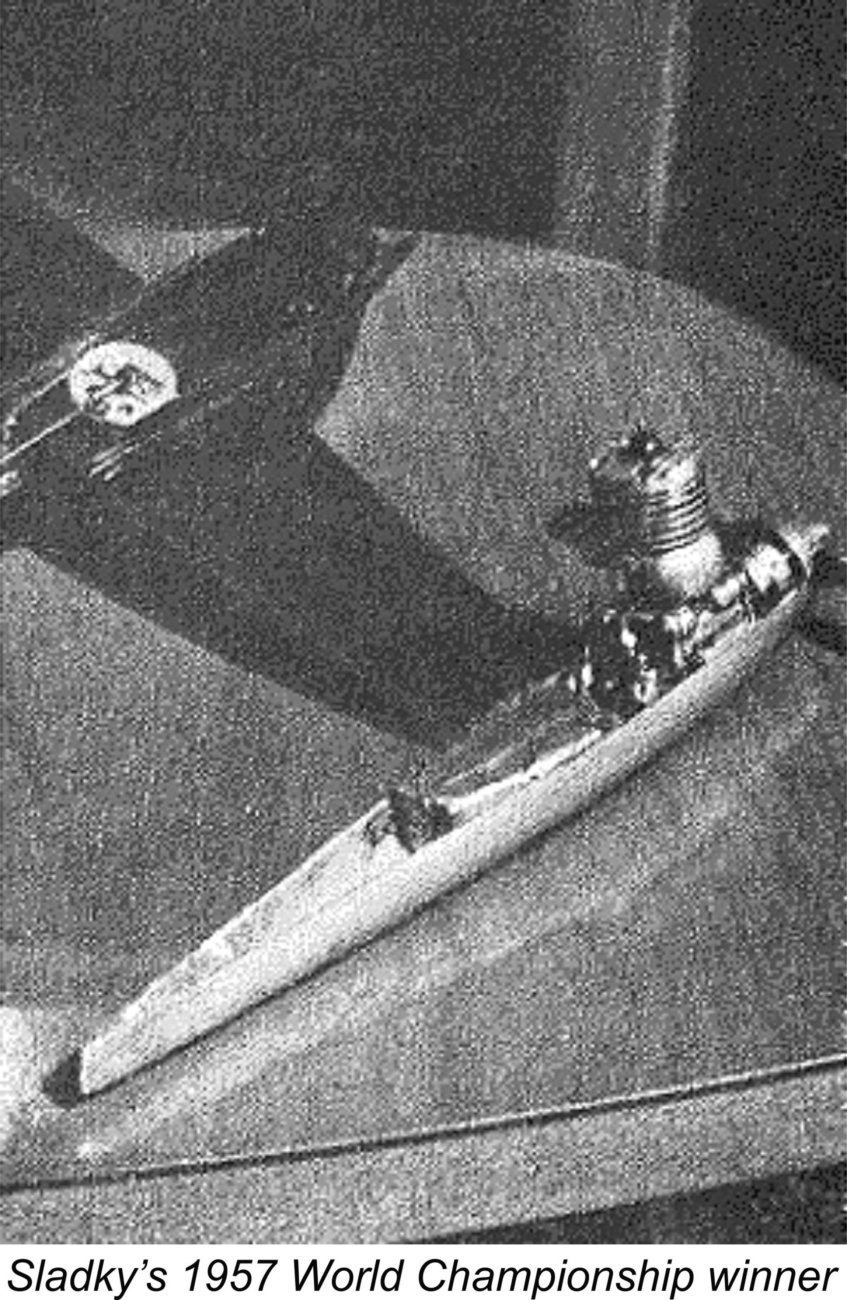 second, it becomes intuitively apparent that a bulge bypass transfer system is best located on the right side of the engine! The swirl effect will then throw the rapidly-moving gas straight into the bulge where it is wanted.
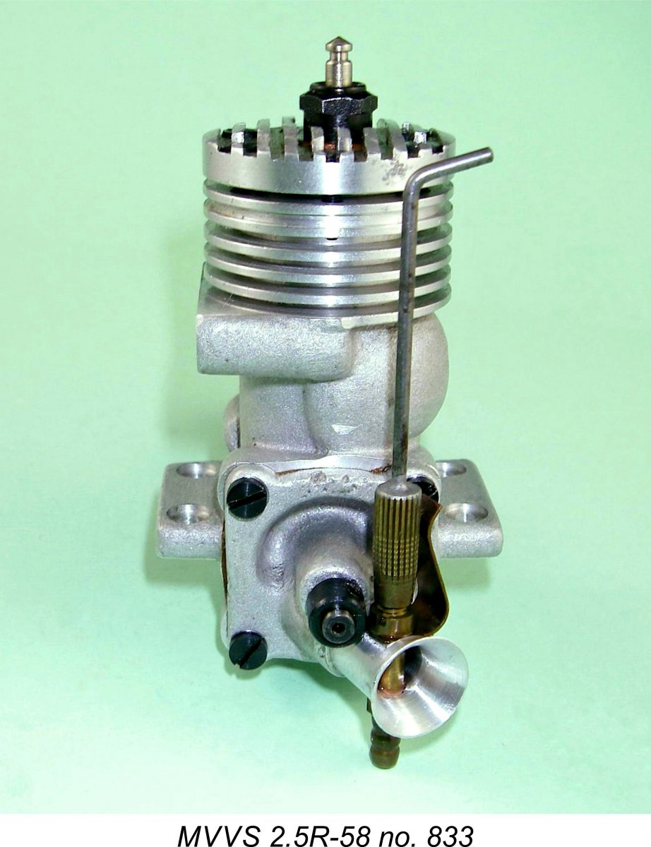 e right (viewed from the rear) and the intake located at the base of the backplate, you’ll see that the cool fresh charge entering the case during the induction phase will swirl with the crank, cool the piston and arrive at the piston ports at just the right time and heading in the desired direction with considerable kinetic energy. In effect, the fresh mixture travels directly from the intake to the cylinder by smoothly traversing a backwards letter "S"!
 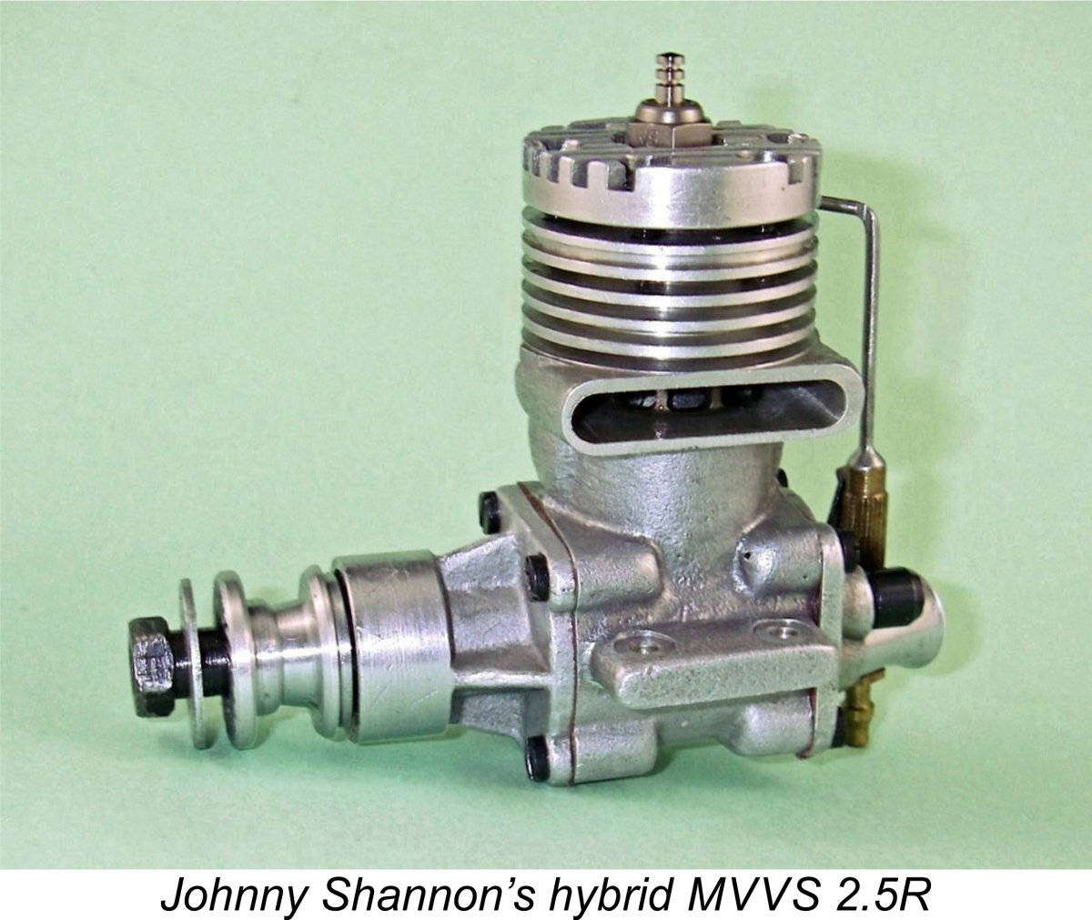 This being the case, I had long had a plan at the back of my mind to test one of my own correctly-assembled and unmodified examples of the engine. An opportunity to do so arose recently in connection with a comparative test of another example of the engine which had been lent to me by my friend Johnny Shannon for examination and test. I decided to test both Johnny's engine and one of my own examples to see how they compared both to each other and to Peter Chinn's earlier findings.
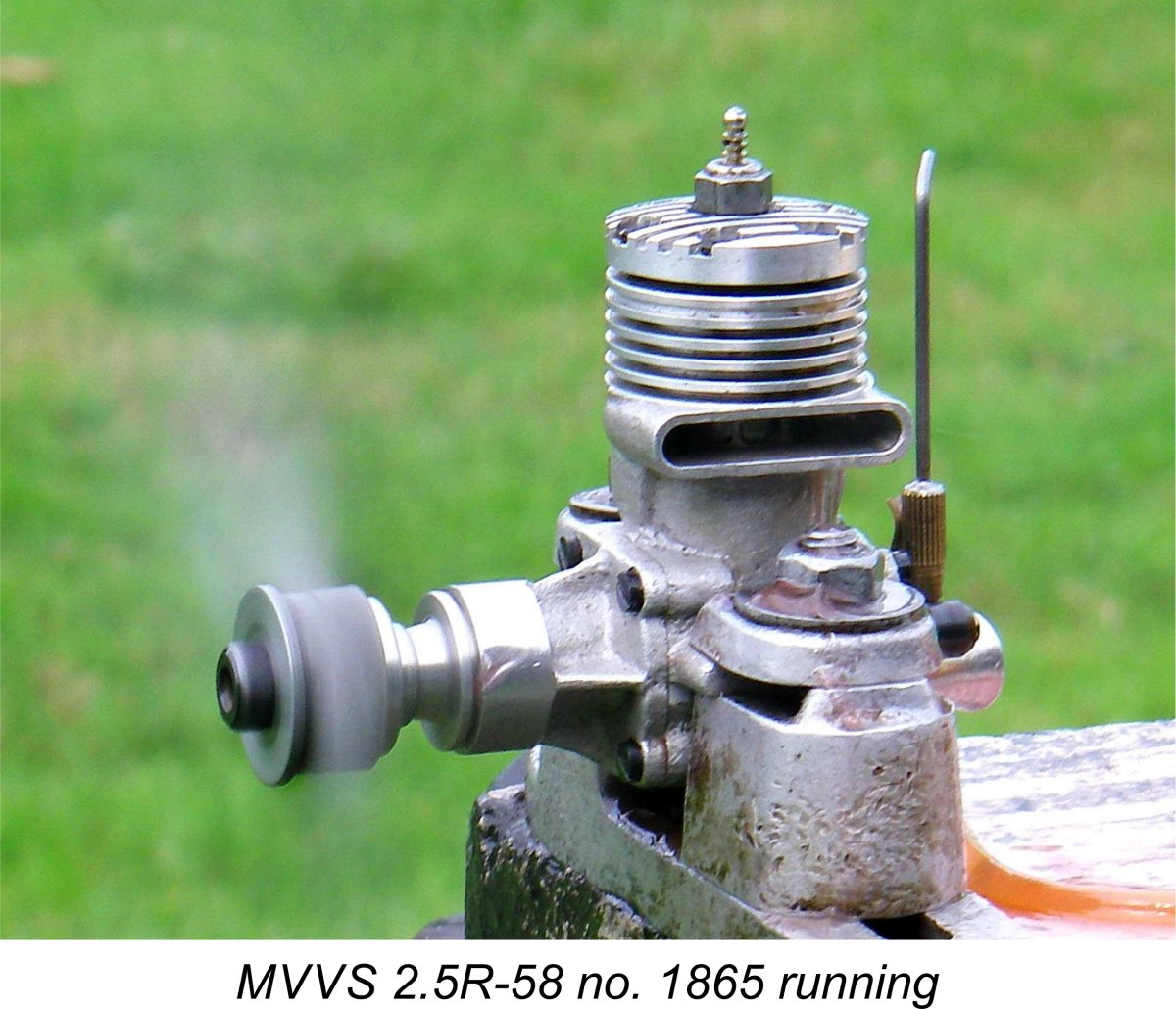

 Even allowing for the fact that I may have an exceptional example of the engine, these are quite stunning figures by 1958 standards. The MVVS factory claimed 0.38 BHP @ 18,500 rpm on 45% nitro for a typical example, while Josef Sladký’s individually selected winning prototype of this engine with which he won the 1957 World Control Line Speed Championships developed a factory-claimed 0.440 BHP @ 19,000 rpm. In fact, the factory went further than that – they actually claimed that subsequent tests on Sladký’s winning engine had shown flash figures as high as 0.61 BHP @ 22,000 rpm on a fuel containing 40% nitromethane and 20% nitro-benzene.
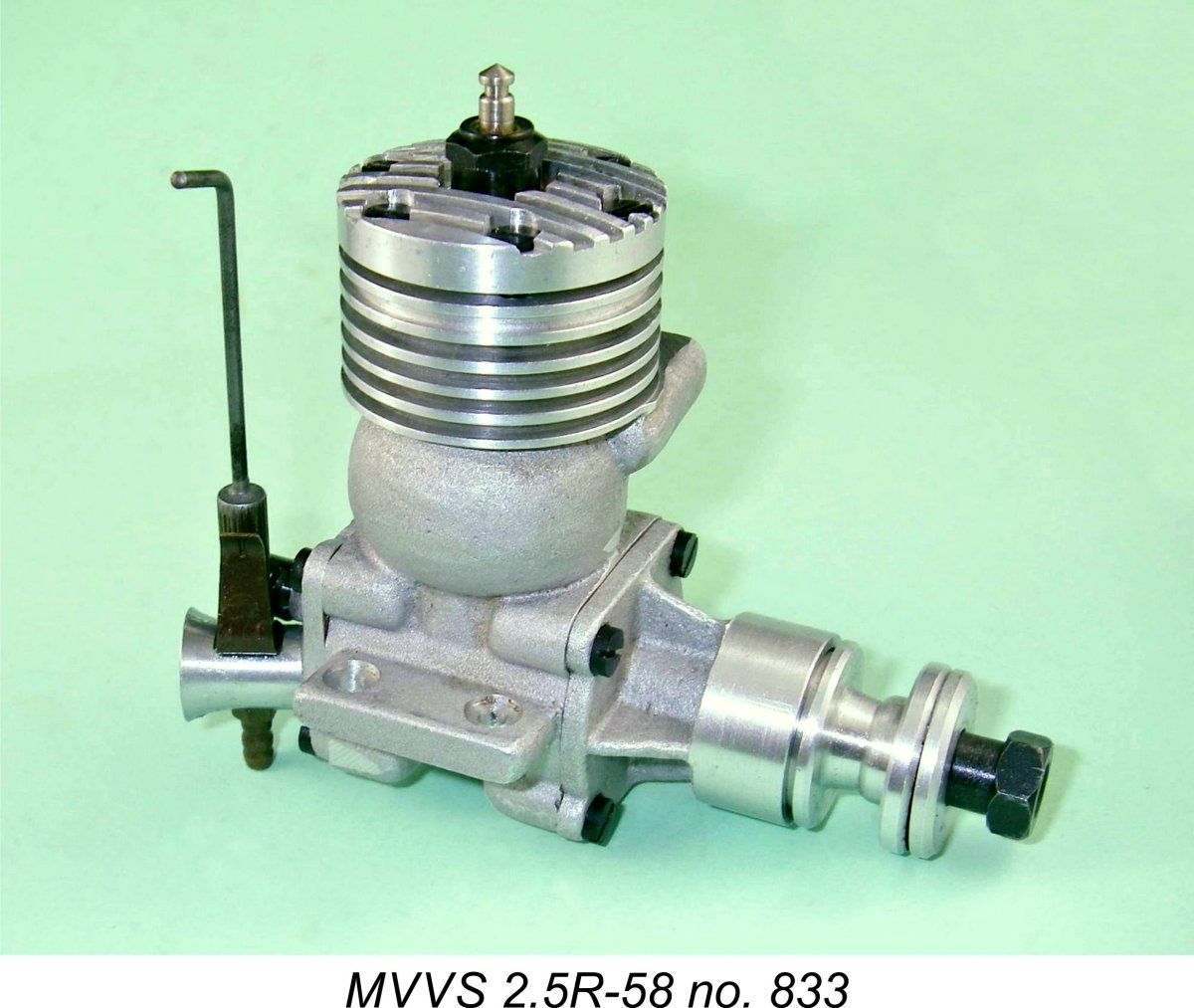 improvements developed for the 2.5R-59 (apart from the needle roller big end bearing). This possibility is certainly consistent with its high serial number - it is clearly one of the engines manufactured later in the series, when further improvements might logically be expected to have been developed and incorporated.
| |