
|
|
Big-Bore Beauties - the Mamiya 60 models
I began this series by publishing an article chronicling the overall history of the Mamiya model engine range from start to finish. Readers wanting a general overview of these engines are referred to that article – here I’ll focus strictly upon the Mamiya .60 cuin. models. As noted in that overview chapter, the very first product of Minoru Sato’s new Tokyo Hobbycrafts model engine manufacturing venture appears to have been the .61 cuin. Mamiya 60 FRV spark ignition model to be described in detail below. This model was most likely introduced in 1948, although this date is by no means firmly established. It may seem surprising that a new manufacturer would enter the model engine field with such a large engine. A design of this displacement would appear to have relatively limited sales potential based on size, range of practical applications, cost of the required large models, space requirements both to store and to fly them, model transportation challenges, cost of fuel, perceived handling “ferocity” and relative price. Hardly a beginner’s or sport-flyer’s cup of tea, one would think!!
The use of spark ignition with its variable timing coupled with the low compression ratios then employed did much to reduce the starting viciousness which present-day modellers tend to associate with the larger displacements - these engines are generally pussy-cats to hand-start, as I know from extensive first-hand experience. In addition, petrol was cheap - fuel costs only became a significant factor when glow and diesel fuels became the norm. The above observations do not alter the fact that mass sales could scarcely have been expected for model engines of this displacement, physical size and associated cost, especially in the context of the shattered post-war Japanese economy. We must therefore look for other motivations for their post-war production. These motivations must have appeared very strong, since almost all of the early post-war Japanese manufacturers challenged the .60 cuin. “big bore” displacement category at some level very early on in their existence.
By contrast, many of the Japanese “big bore” models of the mid to late 1940’s were “racing” designs which were clearly directed towards the high-profile “all-out” competition classes in which such engines could compete. It seems highly likely that the post-war emergence of control-line flying had much to do with this, since it allowed the operation of large racing engines at full power in models which remained both controlled and effectively restrained. The achievement of Japanese success in the all-out horsepower categories such as control-line speed was doubtless seen as highly desirable from both promotional and nationalistic standpoints. It actually appears likely that engines in this large displacement category were seen as “prestige” or “flagship” products which emphasized the technical credentials of their manufacturers. They may also have been intended to represent a statement Fair enough, but bragging rights alone would not have sufficed to justify such expensive and low-volume (in a sales sense at least!) products. The other factor which was undoubtedly at work here was the sudden mid-1945 arrival in Japan of the numerous and predominantly American army of occupation. American modellers had long been attracted to larger models, making it inevitable that the numerous American service personnel having an interest in modelling would be seen as a ready-made “overflow” market for the big-bore Japanese engines which appeared in the latter half of the 1940’s. These individuals had discretionary spending power far in excess of that of the average Japanese citizen in the war-ravaged Japanese economy of the day. Accordingly, they constituted a well-empowered customer base for such large and relatively expensive engines, being in a position to buy whatever the domestic market could not absorb. It also appears likely that the idea of getting some of these large “prestige” engines into the hands of American modellers was seen by the emerging Japanese manufacturers as an Whatever the reasons, there’s no doubt whatsoever that at the time in question (the late 1940’s), large model engines were something of a preoccupation with the emerging Japanese manufacturers. O.S. had been making engines in the 10 cc range since before WW2 and had focused strictly on the further development of engines in that displacement category after the war. As of 1948 they had a very sophisticated rear drum valve twin ball-race .64 cuin. racing design which was made available in Hope produced a finely-crafted disc-valve .60 cu. in. racing model in both spark and glow-plug ignition versions, while the Osaka-based makers of the TOP range reportedly also produced a very few 10 cc racing specials. Enya joined the party in late 1949 with both racing and sport versions of the famous Typhoon .63 model, which drew considerable attention to the newly-founded Enya range. The Kondo brothers were also early in the field with a .60 cuin. KO (Kondo Otoko - Kondo Brothers) glow-plug racing model of their own. Indeed, there All of this activity makes it readily apparent that there was a well-entrenched perception at the time among Japanese manufacturers that the “big engine” field was a highly viable one from a prestige and business development standpoint if nothing else. Clearly, Tokyo Hobbycrafts felt that their entry into this high-profile field at the outset would constitute an unmistakeable statement of their credentials as engine manufacturers. However, at this stage Tokyo Hobbycrafts chose to stand aside from the “racing engine” mania then prevailing among Japanese manufacturers. Instead, they concentrated on producing a top-quality and relatively lightweight FRV general-purpose model, presumably reasoning that there was less direct competition for such a model at the time. Let’s have a close look at this extremely interesting design. The Mamiya 60 FRV Spark Ignition Model
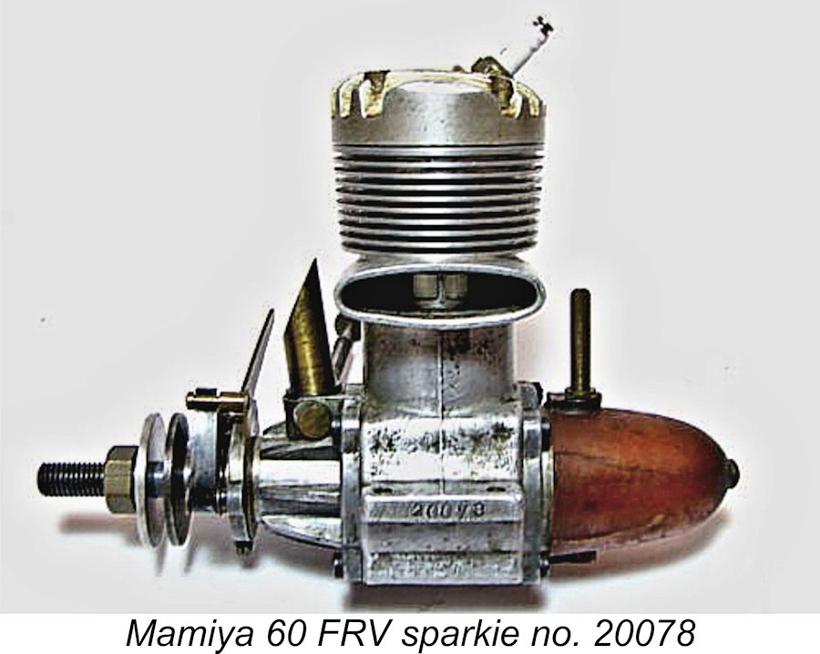
Measured bore and stroke are 24.0 mm and 21.6 mm respectively for an actual displacement of 9.77 cc (0.596 cuin.). My own two examples with their reproduction metal tanks but minus timers weigh in at a commendably light 10.97 ounces (311 gm), which drops to 10.24 ounces (290 gm) minus both tank and timer. My English correspondent Alan Strutt owned a very rare complete example (engine no. 20035) with the original plastic tank which weighs 10.83 ounces (307 gm) with tank, plug and timer. The original Mamiya 60 was (and is!) a very striking-looking design incorporating several unusual features. The first of these is the fact that, unlike the majority of its early post-war Japanese competitors in its displacement category, the original Mamiya 60 was not a racing design but was instead a very well-designed and competently-executed general-purpose model which was a direct descendant of its pre-war forebears. It’s true that the Mamiya 60 FRV sported a die-cast conventional “racing engine” crankcase with integrally-machined cooling fins, bolt-on front and rear covers and a piston/cylinder combination which together adhered very closely to the established big-engine “racing” pattern of the day. It seems not unlikely that designer Sato was hedging his bets at this stage by leaving the door open for a later entry into the racing engine field, a step which was actually taken within a year or two, as we shall see. However, the similarities ended there. The engine featured crankshaft front rotary valve (FRV) induction configured around a plain-bearing crankshaft running in a bronze-bushed main bearing which was encased in a heavily-braced die-cast bolt-on front housing. The backplate was also a bolt-on item which featured provision for a back tank (usually missing on surviving examples), apparently confirming that this model was intended for general-purpose use rather than all-out competition.
My own two examples are equipped with “look-alike” metal tanks of my own manufacture. In the interests of conservation, I would recommend strongly against actually trying to run one of these engines using an original tank. The tank featured an interesting layout, having a streamlined bullet shape with a tall brass filler spigot in the top and a supply spigot underneath. This latter spigot was connected to the spraybar by a 3 mm (not 1/8 in.!) copper fuel line running beneath the crankcase and then up around the bearing to the supply end of the spraybar. This system looked very classy as supplied, but it did have three major disadvantages in addition to the limitations of the tank material. One, the use of a fuel tank other than the supplied component was greatly inconvenienced. It was necessary either to cut the metal fuel line at some convenient location to allow connection to an alterative fuel supply line, or to use a different needle valve assembly. Two, the engine as supplied could only be used in the upright mounting configuration. And three, the tank had a somewhat marginal capacity for this very thirsty engine. My own similarly-sized metal tanks yield a run of around 1 minute 15 seconds on glow-plug ignition, which is adequate for free flight use but not for any other purpose. For control line or R/C applications, it would be absolutely necessary to make alternative fuel supply arrangements. These factors together may well have made their own contribution to the present-day rarity of original tanks with these engines.
The cast alloy cylinder head too was noteworthy, featuring fins which were higher at the front than at the rear (another feature emulated by Enya in their initial die-cast .19 and .29 models of 1953) allied with a steeply-angled ¼-32 plug located very individualistically at the rear of the head. Most unusually for such a large engine, only four screws were used to retain the head in place. This may have given rise to sealing problems, as we shall see when we come to examine the Mamiya 60 RV model in the following section of this article. The fact that no gasket was used to seal might also have contributed to this problem - the head was simply lapped onto the top of the liner. A recessed "blowout proof" gasket in the head would likely have done a far better job of creating a durable seal.
The lightweight ringed light alloy piston was very reminiscent of that used in the contemporary McCoy 60 Series 20 model apart from the fact that the baffle in the domed crown was configured in a wide V-shape rather than being a straight-across feature. The combustion chamber in the cast alloy head was contoured to match. This feature alone makes the engine noteworthy, since Japanese manufacturers of this period almost invariably used lapped pistons, even in their larger engines. As far as I am presently aware, the Mamiya 60 was the first Japanese production engine to use a ringed alloy piston. The crankshaft was also unusual in that the counterbalance was not integral with the rest of the shaft but was a separate component made of brass which was riveted onto the plain disc crankweb.
The lovely brass venturi had a bore of 8 mm, which combined with a spraybar diameter of 3.5 mm to give excellent suction potential for an engine of this displacement. The brass carburettor assembly harmonized with the brass timer components and copper fuel plumbing to give the engine a really classy appearance. The cylinder heads were colour-anodized to further enhance the visual appeal of the engine. The anodizing on these engines does not appear to hold up well in use - many of the un-restored used examples which one encounters from time to time are quite badly faded, presumably from heat.
Engine numbers 20149 and 20135 offered on eBay in 2008 and 2013 respectively also sported the gold head, as did engine number 20130 which appeared on eBay in early 2009. Previously-illustrated engine no. 20078 also has such a head. It appears from these observations either that the two types of head were intermingled freely throughout the serial number sequence or that many owners retro-fitted their engines with gold heads in a search for more power. The unusually complex needle valve assembly is well worthy of comment. The spraybar is externally threaded at the needle end to accommodate the retaining collar, also being threaded internally for the needle. The fuel supply end takes the form of an integrally-machined end-cap which is drilled The needle is an externally-threaded composite affair made up of three distinct components. Some needles are rigid, while others have been seen with a flexible spring section between the friction disc and the control knob. A leaf spring steel arm is used to provide tension by bearing upon the serrated inner thimble of the needle. Overall, the fuel supply arrangements are relatively complex, hence presumably being considerably more expensive to produce than the conventional equivalent.
There have been unconfirmed reports from Japan that factory-built glow-plug versions of this engine may have followed the I am aware of one example – engine no. 20178 - which was claimed to be an original glow-plug variant, being fitted with a red-anodized metal tank which lacked the plumbing associated with the original sparkies. However, this serial number lies well within the authoritatively-established range for the spark ignition models, making the engine’s claimed original glow-plug status appear highly questionable. It seems far more likely that this example is a later owner conversion. It's possible that the alleged factory glow-plug version of this model (if it even existed) was simply a spark ignition model with the timer and plastic tank omitted. Whatever the facts of the matter, the majority of the examples of this model which crop up periodically today in glow-plug configuration appear to be spark ignition versions which have lost both their tanks and their timers. There’s no doubt whatsoever that many of these engines ended up being operated as glow-plug motors, whatever their original specification.
At present I’m unable to say how long the Mamiya 60 FRV model remained in production. However, one may hazard a fairly secure guess that it would likely not have survived much if at all past 1949 as a spark ignition model. The Mamiya 60 models appear to have been the only series-production Mamiya engines to be routinely assigned serial numbers. With a single exception to be discussed below, all of the FRV Mamiya 60 engines of my direct or indirect acquaintance have had 5-digit serial numbers How many were made? Well, the above information on serial numbers seems to imply that this engine was produced in rather limited quantities - perhaps 600 units over an 18-month period at most. This would certainly explain the relative present-day scarcity of these fine units. It would also be consistent with the notion that the engine had a relatively short production run and did not survive past 1949. Fortunately, these engines are rather too large to be readily “lost” or simply discarded and are sufficiently well built that people valued them, tending to keep them “just in case”. Consequently, a significant number of those which were produced are evidently still with us today. They appear from time to time on eBay, albeit often selling for some pretty inflated prices ……………… An Odd-Ball Serial Number .............
What set this one apart was its serial number - 10011. This makes it look like an early example (number 11) of a new series of these engines featuring a "1" prefix in place of the "2" used by all other examples of my acquaintance. The question is - what set it apart to the extent that the manufacturer felt it necessary to start a new serial number sequence? Manufacturers normally do this only when significant design changes are made to a given design. Since no such changes were externally apparent, the basis for the new serial numbering sequence must relate to internal design changes. Could this be a limited-edition factory-tuned series? In the absence of an example of this series to examine, I'm unable to say more at the time of writing. I just thought that the reader's attention should be drawn to the existence of this anomaly. The Mamiya .60 Racing Glow-Plug Model
This model is extremely rare today, so I’m extremely fortunate in owning two examples, both in fine condition. These are the only examples which I’ve ever encountered personally in the metal. My good fortune enables me to include a few images and some details of this extremely elusive powerplant. Measured bore and stroke of my two examples of the Mamiya 60 RRV are identical to those of the FRV model described earlier at 23.90 mm and 22.20 mm respectively for an unchanged displacement of 9.96 cc (0.61 cuin.). The RRV engine is notably compact and lightweight for a racing engine of this displacement - it weighs in at just 278 gm (9.80 oz.), which is actually less than its FRV counterpart described earlier. This makes it one of the lightest racing 60’s ever manufactured. The above bore and stroke measurements are consistent with those given in the summary of the “World’s Model Engines” which appeared in the early 1958 British publication “Model Aero Engine Encyclopaedia”. However, there is a substantial discrepancy in the weight figures. The table in the referenced publication gives the weight of the Mamiya 60 RRV as a very hefty 16 ounces, which is very much at odds with the figure for my examples. The quoted speed range was 10-16,000 rpm - a typical spread for a 10 cc racing engine at the time.
The crankcase casting appears to be identical to that used on the earlier FRV spark ignition version. My English correspondent Alan Strutt owns an example (illustrated engine no. 00763) on which the exhaust is conventionally located on the right side of the engine (facing forward) - the revised head design with a vertical plug installation configuration allows this with no complications. My own example no. 00754 arrived with the stack on the left, and the fact that the engine appeared virtually unused coupled with the unmarred condition of the front housing mounting screws suggested that this was the original configuration. Since both orientations were undoubtedly used on the earlier FRV spark-ignition model, there’s no reason to suppose that the same option might not have been offered for the RRV glow model as well.
The induction disc is made of aluminium alloy, in common with other contemporary racing models such as the McCoy 60 Series 20, the Nordec RG10 and the ETA 29. It is very well supported on a steel shaft which is cast into the disc itself and runs in a thin-walled bronze bushing in the centre of the backplate. No form of retention is included - the disc is maintained in contact with the backplate surface purely by crankcase pressure. Minoru Sato appears to have been among the first model engine designers to appreciate the practicality of this arrangement, which minimizes incidental power losses due to disc friction.
The eminent English model engine designer “Gig” Eifflaender of P.A.W. fame used to comment that a single ball-race version of a given plain-bearing engine might be 10% faster, but a twin ball-race version of the same engine might be 3% slower unless the races were perfectly aligned. This requirement would obviously contribute to increased manufacturing costs if the potential advantage of the second ball-race was to be realized consistently.
The two examples of the Mamiya 60 RRV in my possession are quite distinct. What appears to be the earlier of the two (engine no. 00706) features a cylinder head which at first sight seems to be of the type used on the earlier sparkers, with rear-angled plug. However, a closer examination of the actual engine reveals A feature which is extremely difficult to rationalize is the continued use of only four screws to retain the cylinder head. This appears to be a quite inadequate arrangement for a 10 cc high-compression racing engine. After all, they used six cylinder head hold-down screws for the smaller 29 RRV model! Since they were producing a different cylinder head in any case, why didn't they increase the number of screws used on the 60 RRV?!? We'll never know .............. The measured compression ratio with this head fitted is a very healthy 11:1, and it certainly feels like it when the engine is flipped over with a plug installed! This implies that the motor was configured to run on straight methanol/castor oil fuel. This is not really surprising given the fact that nitromethane was almost impossible to obtain in early post-WW2 Japan and was prohibitively expensive when it was available. The very high compression ratio also implies that this variant was expected to operate at substantially higher speeds than its FRV predecessor.
Despite the fact that its front housing has no provision for a timer, this example also has a steel prop driver of the earlier spark ignition pattern, complete with cam. This is mounted on a square section of the shaft forward of the main journal. Closer internal examination reveals that this engine is actually fitted with a standard FRV crankshaft complete with induction port and square prop-driver mounting extension. The induction port now serves no function other than supplying lubricant to the middle of the main bearing. This example is built up around a crankcase which appears to have been intended originally for use in a spark ignition model, since the case bears the stamped-on Tokyo Hobbycrafts identification on the bypass-side mounting lug, which the later examples of the Mamiya 60 RRV do not. However, the fact that this case was used from the outset in RRV configuration is confirmed by the fact that it bears the serial number 00706 stamped onto the exhaust-side lug - no sign of the 20xxx numbering configuration applied to the FRV models. All of these observations point towards the conclusion that this unit almost certainly began life as a standard Mamiya 60 FRV spark ignition model which was used as a test-piece for the development of the RRV version. The conversion was effected (possibly in successive stages) by replacing the cylinder head and piston, replacing the front housing with a new casting which lacked provision either for a timer or for FRV induction, and also replacing the standard backplate with a disc valve assembly. All other components are of the standard FRV spark ignition pattern - further revisions to the cylinder head, crankshaft and prop driver came later.
I've run this particular engine, finding it to be a very easy starter and a fine runner. Not owning an electric starter, I had to hand-start the brute. As usual with large high-compression glow-plug racing engines, hand-starting requires a somewhat different technique. Set the prop at "ten past eight" with the piston at bottom dead centre, prime the exhaust port, light the plug and hit the prop backwards from bottom dead centre hard enough to bounce the piston up the bore to the point where the mixture fires. The inevitable backfire almost always starts the engine in the normal direction with no risk to the starting finger.
A few prop/rpm figures obtained during this test included 11,400 RPM on an APC 11x6 (0.843 BHP), 12,200 RPM on an APC 10x7 (0.888 BHP) and 12,300 RPM on an APC 10½x6 (0.888 BHP). I wasn't willing to push the engine any faster. Although by no means a representative set of figures, these data imply a peak output of somewhere around 0.90 BHP @ 12,300 RPM. While offering no threat to the contemporary Dooling 61 and McCoy 60 Series 20, this is still a very impressive performance for a 1950 engine weighing less than ten ounces running on straight FAI fuel. It would doubtless do far better with some added nitro provided that the head seal could take the increased pressure.
My example of this variant is unmodified and seemingly very little used. It features an updated head having a vertically-oriented glow-plug which is offset towards the transfer side. The piston has a conventional straight-across baffle, with the head being contoured to match as illustrated earlier. In addition, the head fins now have a squared-off profile rather than being rounded as they had been formerly. The motor also features a nicely-executed aluminium alloy prop driver in place of the earlier steel item. Measured compression ratio of my example of this model is a healthy 10 to 1. Rather surprisingly, the head continues to be retained by only four screws - a seemingly inadequate arrangement, particularly for a high-compression racing engine. Alan Strutt owns identical engine number 00763.
The high compression ratio suggests that it would be unwise to prop this engine for speeds below 10,000 rpm or so, otherwise pre-ignition would likely occur. I used an 11x6 prop for my testing, but I feel that an 11x5 or even an 11x4 would be preferable - this is not a low-speed engine! A cold plug would also appear to be indicated if leaned-out running is contemplated. Alan Strutt has also run his example and in doing so has confirmed what appears to be a design glitch with the overall Mamiya 60 series. My own examples of these engines, both RRV and FRV, all use a lapped interface between the head and cylinder flange to create a seal. By contrast, Alan’s RRV model uses a gasket between the head and cylinder flange - whether this is original or an owner modification is uncertain. It appears from Alan’s experiences that the maintenance of a good head seal with only 4 head screws is a somewhat marginal proposition, especially for flat-out glow-plug operation. The rather narrow width of the sealing area employed and the relatively large sealing circumference doubtless contribute to this issue. My own tested engines have maintained their seals OK, but even so there was a certain amount of visible “weeping” of oil past the sealing area during flat-out operation. The slightest warping of the head would give rise to major sealing problems. Logic persuades us that the spark ignition FRV versions with their variable ignition timing must have been OK – Minoru Sato must surely have tested these engines, and it’s very difficult to see why he would make 500 examples of a model that didn’t work! The low-compression version of that model certainly seems to work OK on glow-plug ignition, so presumably the spark ignition models did likewise. However, operation on glow-plug ignition gives rise to very different conditions in the cylinder, particularly when using higher compression ratios. It’s difficult not to feel that an increase in the number of cylinder head hold-down screws would have been a prudent step to take when creating the Mamiya 60 RRV model. Like their FRV predecessors, the Mamiya 60 RRV engines display serial numbers - my example of the second variant bears the number 00754 while Alan’s identical motor carries the number 00763. Together with my early variant no. 00706, the cited figures are the only three confirmed serial numbers for this model in my possession as of 2026, when this article was re-written. The Mamiya 60 RV appears to have been manufactured in very limited quantities - examples are extremely rare today. I suspect that the first "0" digit is the model identifier for the disc valve glow-plug version of the Mamiya 60, just as the "2” digit appears to have been for the spark ignition FRV model. The significance of the "1" digit mentioned above remains obscure.
The relative numbers of known survivors argue very strongly against this possibility - the 60 RRV is far less frequently encountered than the companion FRV variant, which is itself far from common. Looking at the matter quite objectively, it seems more likely that the numbering sequence for this model started at some intermediate point. In that regard, the most logical assumption is that the serial numbering sequence for the Mamiya 60 RRV started at 00701. This starting point would be completely consistent with the previously-expressed idea that my lower-numbered example is one of the first such engines produced. The fact that it features an earlier-style head along with a spark ignition prop driver and shaft certainly seems consistent with the idea that it was assembled at a time when the design was still evolving. If the above hypothesis has any validity, we have evidence for the production of at least 63 examples of the Mamiya 60 RV glow-plug model. This is completely consistent with the extreme rarity of surviving examples, which suggests that the number manufactured was very small. Only the provision of more serial numbers for this model would help to resolve this question of numbers. Contributions, please!! One realistic possibility that does suggest itself is the notion that this engine followed directly on from the FRV spark ignition model after production of that model ceased. The fact that there is presently no evidence whatsoever that a spark ignition version of the Mamiya 60 RRV was ever manufactured implies that the switch to glow-plug ignition and the change to RRV induction occurred simultaneously. Basically, the admittedly-scanty evidence available at present suggests that the RRV glow model replaced the FRV sparker rather than being offered simultaneously as an alternative. As noted previously, the Mamiya 60 RRV is included in the listing of the “World’s Model Engines” which appeared as an appendix to the early 1958 publication “Model Aero Engine Encyclopaedia”. This cannot be taken as an indication of continued production, since the above-noted list was already woefully out-of-date at the time of publication. However, it does indicate that the engine was by no means forgotten as of early 1958. It is also worth noting that the FRV version was missing from this list. This appears to confirm that the racing model outlived and most likely succeeded its earlier general-purpose sibling, which is very much in keeping with my earlier speculation. It is certainly evident that the RRV version of the Mamiya 60 was introduced at a later date than the FRV version since it appears never to have been produced in spark-ignition form - at least, I cannot find a report of any original examples of such a model, although owner retro-conversions may well exist. Conclusion Reviewing the above account, it seems likely that well under 1,000 examples of all Mamiya 60 models combined were manufactured in total. This figure certainly explains the comparative rarity of these engines today. The RRV racing glow-plug model is particularly elusive – it seems likely that only 100 or so examples of that model ended up being made at most. Despite this, these engines constitute a legacy of which Minoru Sato could be justifiably proud! No true model engine enthusiast can fail to be impressed by these fine examples of the model engine manufacturer’s craft! Just wear hearing protection if you're ever around one of these motors in operation - they're LOUD!! _________________________ Article © Adrian C. Duncan, Coquitlam, British Columbia, Canada First published April 2026 |
 This is the final article in my series on the various displacement categories in which the Japanese model engines marketed under the Mamiya trade-name were offered to the modelling public. In earlier articles I’ve covered the
 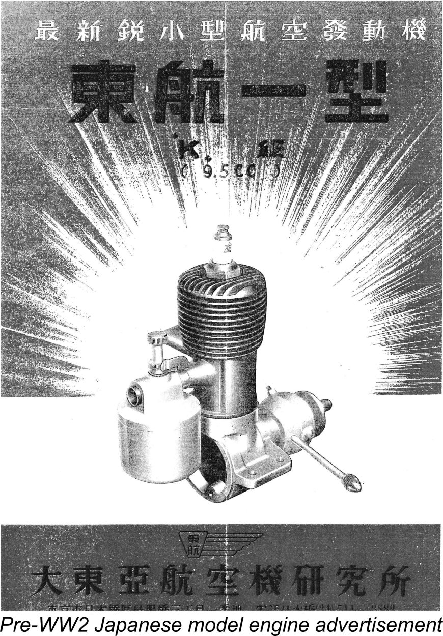 However, it’s always important to examine such seeming anomalies in context. During the period in question in which spark ignition still held sway, larger engines continued to predominate. Serious modellers had become more or less accustomed to the use of engines of .29 cuin. and above even for sport flying, due mainly to the considerable weight penalty imposed upon smaller engines by the use of spark ignition with its attendant battery and coil components. Larger engines and models were the general rule rather than the exception, and powerplants in the .60 cuin. displacement category had been in common use in the thriving power modelling scene which had existed in pre-war Japan, invisible to outside eyes due to linguistic and political barriers.
 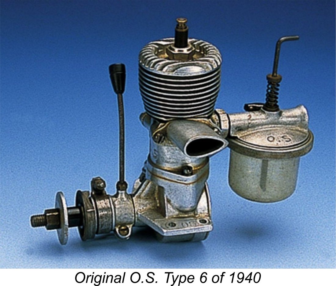 I noted earlier that large-displacement engines had been quite popular in Japan prior to the war. The recollection of this pre-war situation doubtless injected a degree of inertia into the thinking of post-war Japanese designers in terms of displacements with which to work. However, these pre-war designs had generally fallen into the “sport flying” category in design terms - they were intended for general purpose use in the large free-flight models which then predominated.
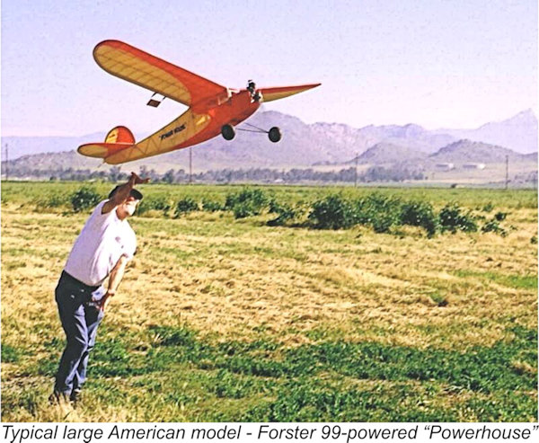
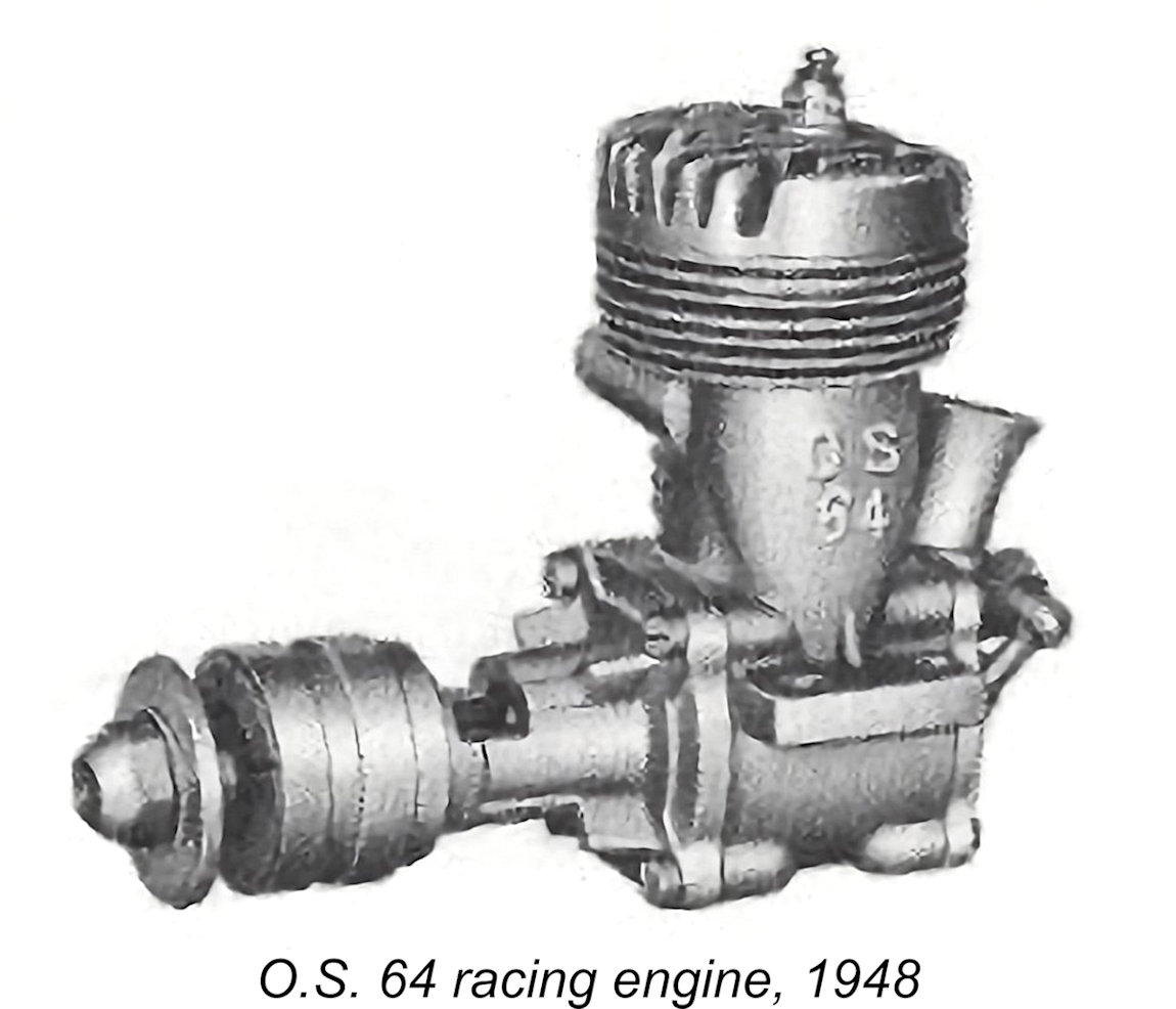 excellent way of promoting their capabilities with a longer-term view towards export of their products to the North American market. Sound thinking if this was indeed the case, and it certainly paid off for both O.S. and Enya.
 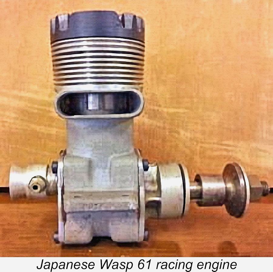 both spark ignition and glow-plug versions. Competition for this offering was provided by a 10 cc model of obscure origin called the Wasp – essentially a McCoy 60 clone. Another equally obscure 10 cc racing model was on offer at the same time under the Super Devil name.
 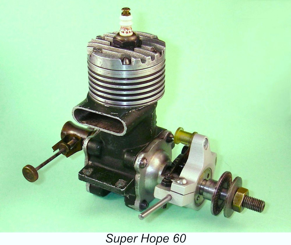 were almost certainly more manufacturers producing 10 cc racing engines in Japan in the late 1940's than there were in America!
 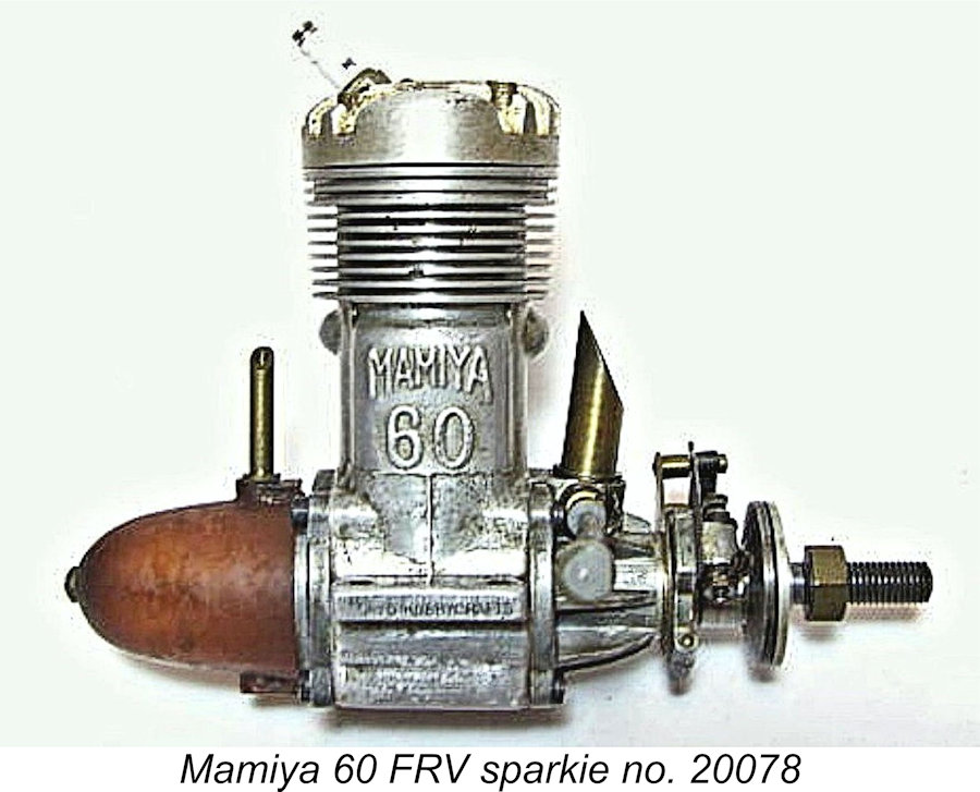 As we might expect from an introductory product bearing the already famous Mamiya name (with the full blessing of the renowned Mamiya camera manufacturers), the standard of workmanship displayed in this engine is extremely high throughout. A full description of this engine may be found in a retrospective
  The back tank as supplied was made of a green-tinted translucent plastic material. The plastic of which this tank was made was most likely one of the early varieties derived from bean curd. As such, it tended to return rapidly to its original organic form, especially under the influence of fuel. Some car steering wheels were made from similar materials at this time, and they too did not stand up well. This likely explains the fact that most examples of this engine encountered today are missing their tanks.
  Apart from the tank and its associated plumbing, the Mamiya 60 possessed several other visual attributes which helped it to stand out from the contemporary crowd. For one thing, the die-cast crankcase was notable for the racy-looking aerofoil-section exhaust stack. This feature also appeared on the contemporary
  At first sight, it might be assumed that the engine could be assembled with the exhaust stack on either side simply by reversing the central casting between the front and rear covers. However, a moment’s thought will confirm that this is not the case - the location of the plug in the cylinder means that a different head casting is required to permit the reversal of the exhaust stack's orientation with the head correctly aligned to accommodate the piston baffle. Such alternative castings were produced, allowing both left and right-hand exhaust versions to be sold - a 2008 eBay offering featured engine number 20348, which retained its timer and had a right-hand stack (and sold for over $1000 despite the usual missing tank!!!). However, the majority of examples feature the left-hand stack configuration.
  An open-frame timer was used, activated by a cam machined into the rear boss of the steel prop driver. The driver was located on the shaft by means of a square shoulder formed on the shaft which matched the broached square section of the central hole in the driver. Hence the driver (and the cam) could be fitted in any one of four different orientations, allowing a choice of timer control arm locations when the engine was mounted in a model.
 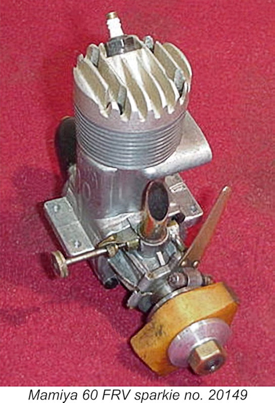 Two types of head were fitted, the standard version being anodized red and the high-compression version being anodized a very pale gold colour, as seen at the left. The checked compression ratios provided by these heads were 8.5 to 1 and 10 to 1 respectively - both relatively high figures for a non-racing spark ignition engine. The head of my earlier example number 20268 is one of the latter versions, while my second example number 20328 has the standard red head. I am also aware of engine number 20178 which had the gold head and had been used in glow-plug service.
 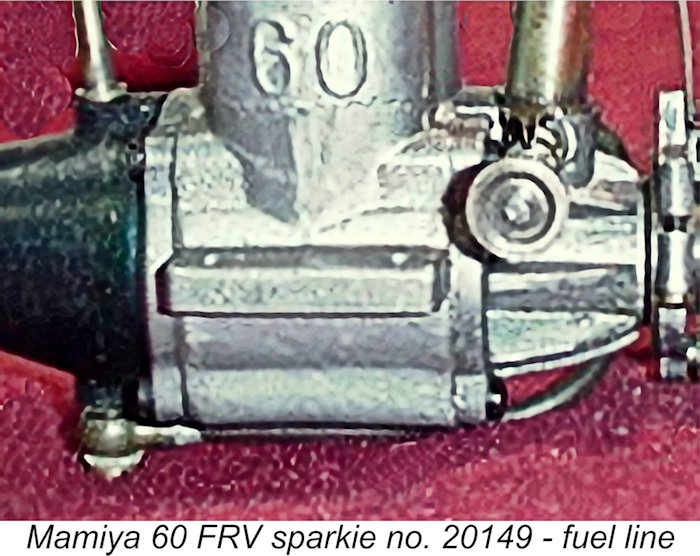 at one side to accept the 3 mm copper fuel line at right angles. The fuel line itself is configured to pass by a rather convoluted route around the main bearing housing and then back beneath the crankcase to hook up with the tank through the use of a banjo fitting. Fibre washers are used to seal both ends of the spraybar assembly - a quality touch. The spraybar is secured on the needle side by a collar having a slot for the application of a screwdriver to tighten it.
 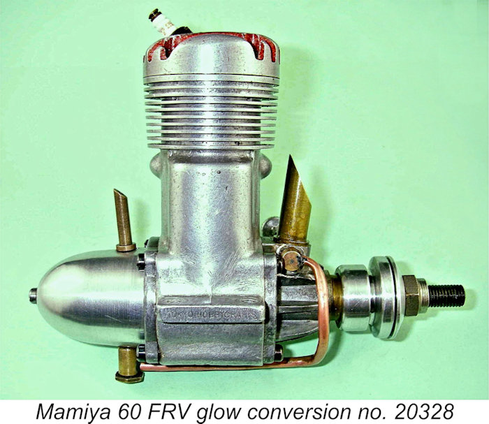 The Mamiya name is cast in relief onto the bypass area of the main crankcase. In addition, the manufacturer’s registered name of Tokyo Hobbycrafts is neatly stamped into the outer edge of the right-hand mounting lug. On my glow-converted engine number 20328, someone has very neatly removed the Mamiya 60 identification by filing and smoothing with emery cloth. It's possible that this action dates from the early post-war years when the Japanese weren’t exactly flavour of the month and a non-Japanese owner may have harboured sufficient lingering resentment to eradicate all overt traces of a Japanese origin. Alternatively, a Japanese seller may have done the same to make the engine more palatable to prospective overseas buyers. I’ve encountered evidence of such actions in connection with other Japanese products from the early post-war era.
 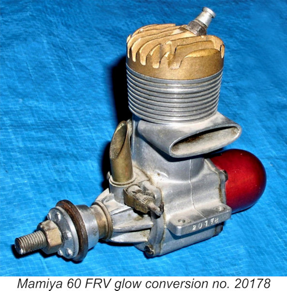 spark ignition model, at least for a time. However, indisputable examples of this engine in original purpose-built glow ignition form appear to be like hen’s teeth in today’s collector market - I have yet to encounter one in years of looking, nor have I seen any persuasive evidence to support the existence of such a model.
 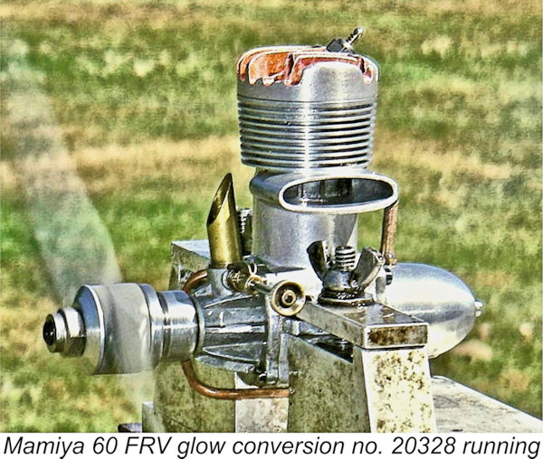 My own engine number 20328 is fitted with a very professionally-made wrap-around alloy prop driver for operation as a glow-plug motor, but there’s no evidence whatsoever that this was a factory option. When tested in this form, the engine ran extremely well on straight methanol/castor fuel using an 11x6 airscrew. Its starting qualities were particularly noteworthy - very docile for a glow-plug engine of this displacement. A small prime yielded a first-flick start almost every time, with a most welcome absence of viciousness. Despite the use of only four head screws, there was no evidence of any significant head joint leakage - merely a trace of oil seepage.
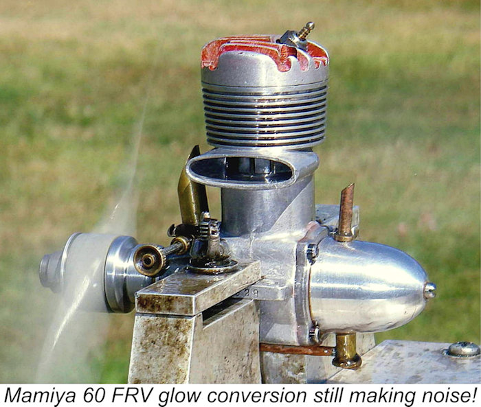
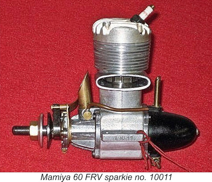 In 2016 a seemingly-pristine example of the Mamiya 60 FRV spark ignition model appeared for sale on eBay. To all appearances, this was just another example of the engine described above, albeit a very nice complete one which retained its tank and sported the gold high-compression head. Its fuel line had been cut to allow the use of a separate tank, but in all other respects it appeared to be a very fine example.
 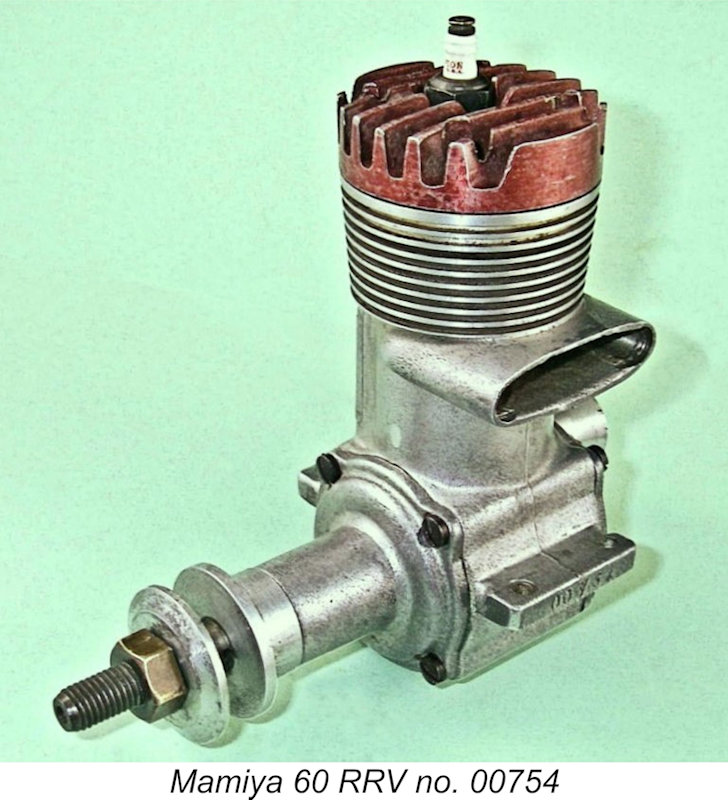 One look at the model just described is sufficient to show that the crankcase layout together with the associated piston/cylinder combination lent itself very readily to conversion to a conventional “racing” layout with ball-bearing crankshaft and disc rear rotary valve (RRV) induction using conventional bolt-on front housing and rear disc valve assemblies. And indeed, such a model was produced following the switch to glow-plug ignition.
 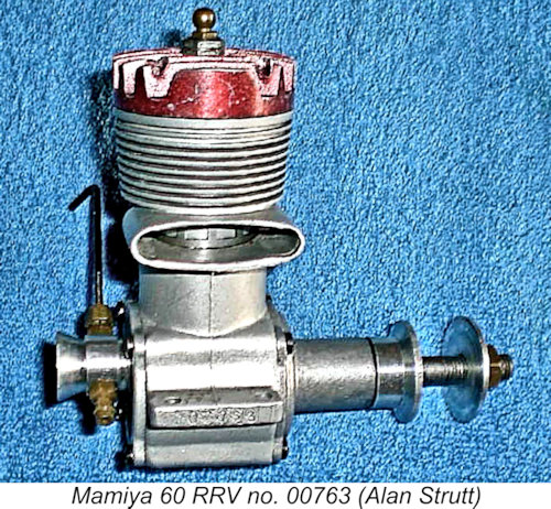 In view of the weight discrepancy, one’s attention is drawn to the possibility that there may have been a later version of the Mamiya 60 RRV of which I’m presently unaware. It’s certainly true that the companion 29 RRV racing model went through several variants, so there’s no reason to suppose that the 60 model could not have been developed further as well. I’d welcome any input from readers in this regard.
 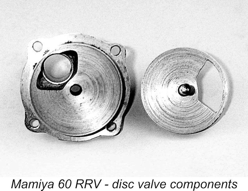 The front housing and backplate are of course completely different given the change in the induction arrangements. The front housing is a plain bolt-on unit without any vestigial traces of the former FRV induction system. The backplate and disc valve are of conventional form, being mainly noteworthy for the very short intake used. The intake venturi has a generous bore of 9.5 mm (0.374 in.). Coupled with the use of a McCoy-style surface jet needle valve assembly, this represented a significant increase in the engine’s induction capacity compared with the earlier FRV spark-ignition model, albeit at the cost of rather marginal suction. In racing service, of course, some form of pressure feed would doubtless have been arranged.
 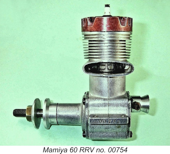 A point of great interest with respect to the front housing is the fact that it utilizes only a single ball bearing at the rear as opposed to the familiar twin ball-race set-up generally seen on racing engines. At first sight this might appear a little odd for such an engine, but in fact there was sound reasoning behind it. The fact has long been recognized that front ball races actually contribute relatively little to engine performance since they are located at the most lightly-loaded end of the shaft (assuming that the prop is well balanced). A ball race at the loaded (rear) end of the shaft does far more to absorb major radial loads, offset friction losses and minimize wear than a front race. In addition, the need to accommodate a second ball race inevitably adds extra weight to the engine, and it is weight which in reality contributes little to the unit’s effectiveness. Finally, the extra ball race represents an increase in cost for relatively little return.
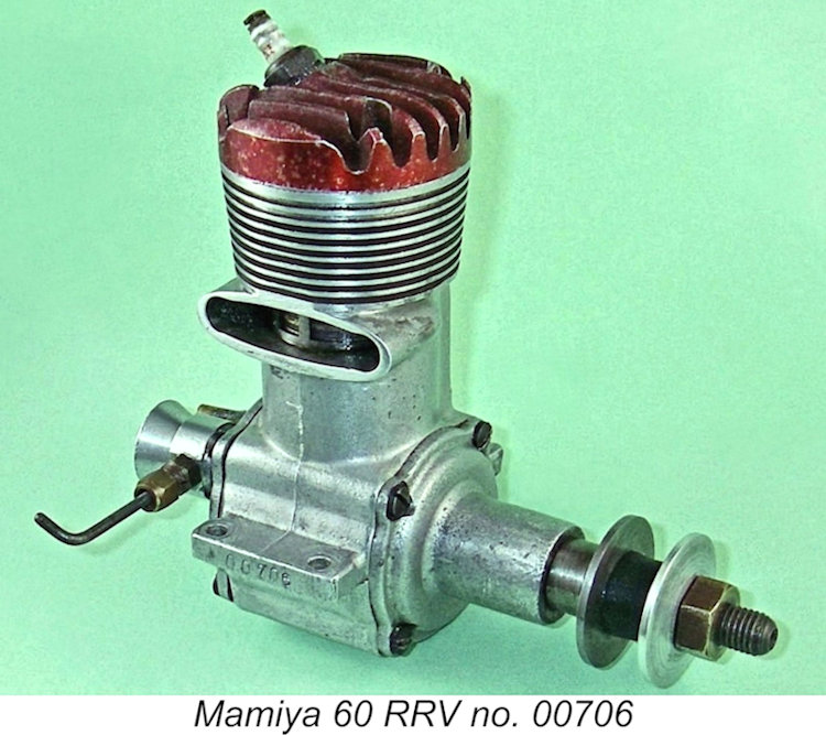
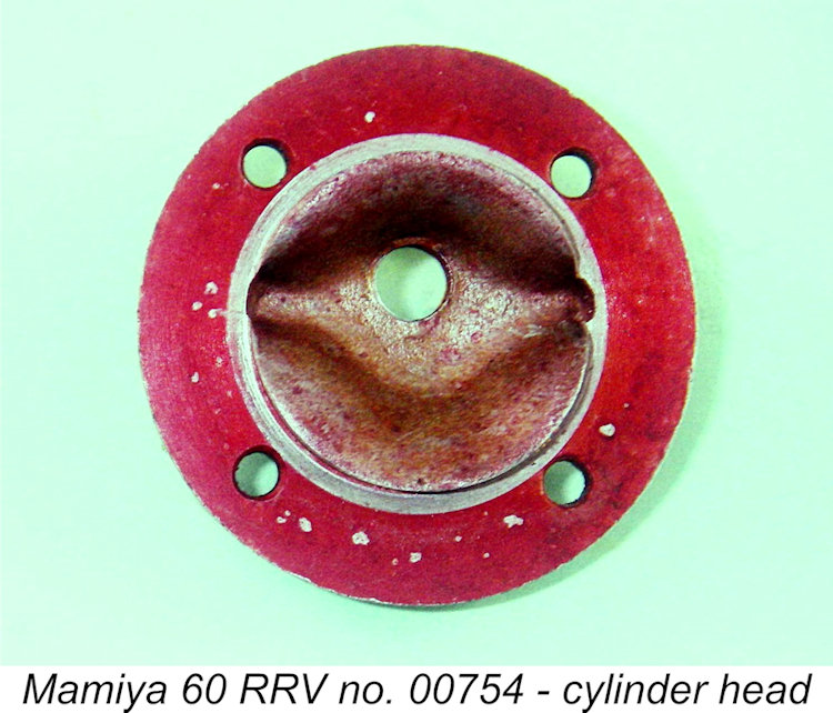 that the combustion chamber is internally configured like that used in the later examples of the Mamiya 60 RRV to accommodate a straight-across piston baffle instead of the wide V-shaped baffle of the FRV sparker. It's actually a different casting featuring the same plug orientation.
 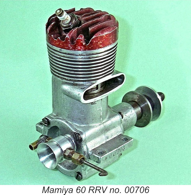 The exhaust stack of this example has been quite cleanly trimmed, presumably to conform to a cowling, while the fuel jet has been equipped with a neatly-executed 90º fuel line attachment. The motor thus appears to have been intended for use in a control-line speed application. Although it has clearly been mounted and has obviously done some running, it remains in excellent mechanical condition.
 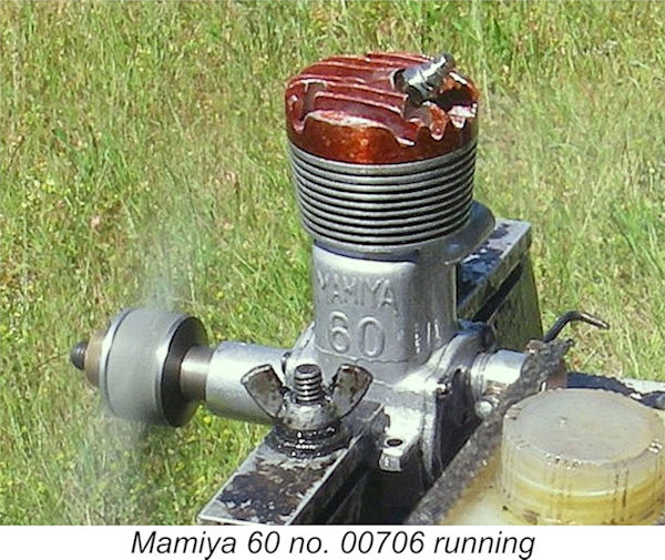 This implies that engine number 00706 is a transition model which is one of the very earliest examples of the RV variant produced, at a time when these engines were being created simply by installing a few replacement components on a standard spark ignition unit. Perhaps they were using up left-over and now redundant FRV components.
 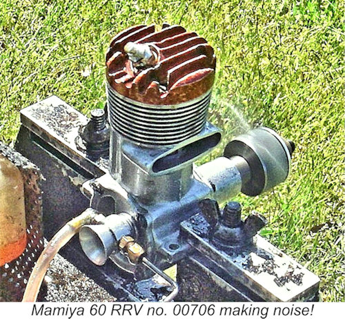 Using this technique with a straight 75/25 castor-based FAI fuel with no nitro and a "cold" Enya no. 6 plug, the Mamiya was a one or two-hit starter every time. Rather surprisingly, suction proved to be perfectly acceptable, while the needle response was excellent - not unduly sensitive, but a very well-marked sweet spot. Running qualities were beyond reproach, with no hint of misfiring or sagging when leaned out. There was some minor seepage of oil through the head joint, presumably due to the previously-noted use of only four cylinder head attachment screws. However, the seal held up OK with no obvious adverse effects upon running.
 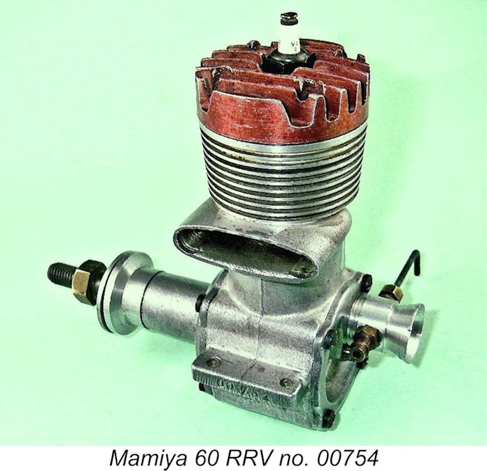 My previously-illustrated second example of the Mamiya 60 RRV appears to represent the final form into which this model evolved. It bears the serial number 00754 on the exhaust-side mounting lug, but does not display the Tokyo Hobbycrafts stamping on the bypass-side lug. In fact, this name was destined to appear on no other Mamiya product. The name did however continue to be included on the boxes in which the engines were supplied, as witness a much later Mamiya 9X engine box of which I have an image available.
 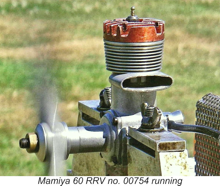 The second variant of the engine starts and runs very well indeed, as my own bench tests have confirmed, although maintaining a good head seal is an ongoing challenge – there’s a certain amount of oil seepage which can’t be eliminated. The high compression ratio dictates the use of the “reverse bounce” hand starting procedure described earlier. This was very effective, with one-hit starts being the norm. Once running, my example ran perfectly and was very smooth in operation, although it has clearly had little if any previous running and remains somewhat tight. This being the case, I only leaned it out all the way for a few very brief periods and didn't bother taking any speed readings.
 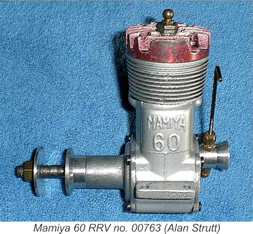 Be that as it may, Alan’s example started up OK on 15% nitro fuel and ran fine on a rich mixture. However, every time Alan leaned out the mixture and the cylinder pressure rose, the engine blew the head/liner seal. Alan tried lapping the two parts together without success and also tried various gasket materials. The most successful of these was a gasket made of thin PTFE sheet, but this too deformed to failure as the temperature rose.
 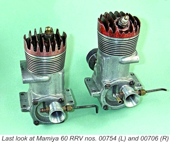 At first sight, the serial number on Alan's example of the engine might be taken to imply that at least 763 examples were made. However, that in turn would suggest that the Mamiya 60 RV was manufactured in larger numbers than its earlier FRV sibling. If Alan’s number was to be taken as an indication that at least 763 examples were made, one would then have to wonder where they all are now ....................
 | |