
|
|
The Dooling 29
The success of the Dooling 61 was such that the thoughts of the brothers naturally soon turned to an expansion of their range. The most obvious additional competition class in which the Doolings could consider participating was the .29 cuin. (5 cc) category, then very popular both in the USA and elsewhere. Accordingly, as 1949 rolled around, plans were put in hand to produce a .29 cuin. racing model to join the established .61 in the Dooling line-up. This became the famous Dooling 29 with which we are concerned here. Once again, the chief designer of this engine was almost certainly Russell Dooling.
There were two primary reasons for this decline. One was doubtless the burgeoning cost of competition at the highest level, which had really moved model car racing out of the “hobby” category. The other was the development of control line model aircraft to the point where very high speeds could safely be achieved under full control and restraint without the need for a special track and at far lower cost. Those power modellers interested in all-out performance now had a less costly and far more convenient form of power competition in which to exercise their engine management talents. Apart from the above factors, by mid-1949 the mysteries of glow-plug operation of model racing engines had been thoroughly explored, not least by the Doolings themselves, to the point where the glow-plug was well into the process of sweeping the spark plug from the field. Virtually all new racing engines which appeared from early 1949 onwards were designed exclusively for glow-plug operation. The new Dooling 29 which appeared in the latter half of 1949 reflected this trend, being offered only in glow-plug form. The spark ignition examples which do show up periodically are later owner conversions. Let’s have a closer look at this outstanding model racing engine. The Dooling 29 Described
The Dooling 29 incorporated a number of signature features which were carried over from the 61 model. For starters, it possessed the same unusually large bore/stroke ratio of 1.35 to 1 derived from bore and stroke dimensions of 0.800 in. (20.32 mm) and 0.594 in. (15.09 mm) respectively for a displacement of 0.299 cuin. (4.89 cc). It weighed in at a checked 197 gm (6.95 ounces) with plug. The new 29 also incorporated the “bulge bypass” transfer system which had been pioneered in the 61 model. This system involves the provision of a large bulbous chamber in the normal bypass passage location. There is no direct communication between this chamber and the lower crankcase, such communication being arranged instead through the provision of three oversized oval ports in the piston skirt which align with matching ports in the lower cylinder liner at and near bottom dead centre. All of the transfer gas mixture thus has to pass through the piston interior into the bypass bulge, from which it is supplied to the cylinder through transfer ports in the usual manner.
On the downside, the presence of the piston ports significantly reduces the area of metal available on the piston’s transfer side to resist side-thrust forces generated during operation. As typically set up with the exhaust on the right, the system also fails to take best advantage of the swirl effect in the crankcase due to crankshaft rotation. I'll comment further on this matter below. Overall, it may be fairly stated that the Dooling 29 was basically similar in concept to the 61 apart from the omission of a timer and a far more compact appearance. The needle roller big end bearing was also dispensed with. The underside of the cast cylinder head was carefully contoured to work with the high-domed twin-ring alloy piston to created turbulence and efficient combustion of the fuel mixture. The compression seal provided by the two rings was outstanding. The piston operated in a thin-walled drop-in liner machined from high-chrome cast iron. It drove the counterbalanced crankshaft through a forged and heat-treated duraluminum rod. The one-piece steel shaft ran in two high-quality ball bearings. The assembly of the prop driver onto the shaft was somewhat unusual. The prop driver was actually a firm press fit on the front portion of the shaft, being further secured by the use of a socket set screw which engaged with a flat on the shaft. If it becomes necessary to remove it for servicing of the bearings, one slackens off the set screw, removes the steel prop nut stud and inserts a ¼-28 bolt into the tapped interior of the prop driver. Tightening this bolt against the end of the shaft pulls the prop driver forward off the shaft. A bit of heat helps very much to accomplish this. I’ve seen a number of examples with prop drivers which have been marred by ill-informed efforts to remove them - I actually own such an example (engine no. 6737) which is in otherwise excellent and completely original condition. No more marred prop drivers, please - do it correctly!
The die-cast crankcases of the Dooling 29 were given an attractive matte finish. Those produced during 1949 featured a long casting sprue on the bottom of the case, while those manufactured from 1950 onwards had a shorter sprue in the same location. The finish used on the cylinder heads varied, some being matte while others were polished. Like its 61 big brother, the quality of the Dooling 29 was well up to the highest industry standards. The standard of surface finish was such that no gaskets were used in the assembly, reliance being placed entirely upon metal-to-metal fits.
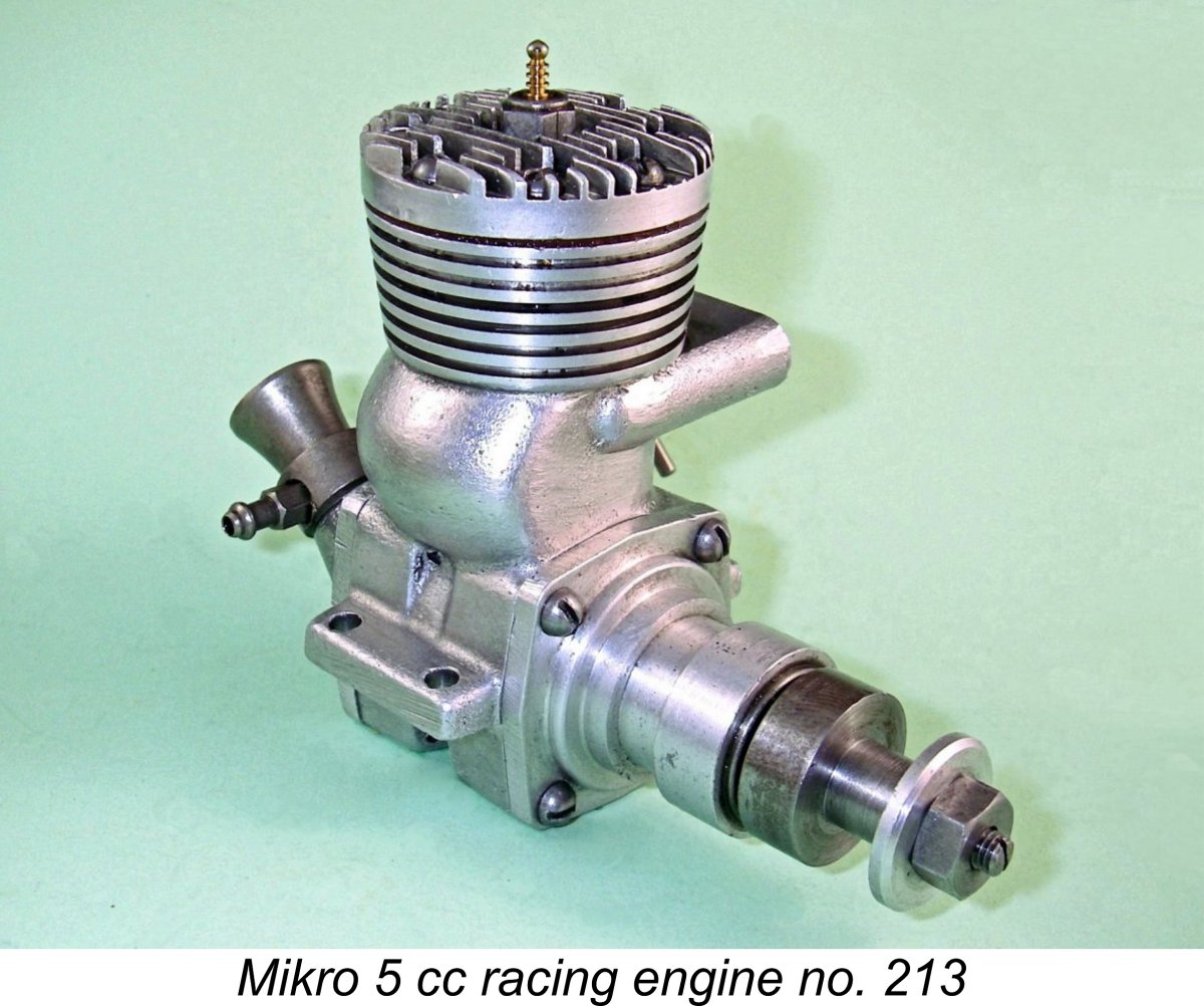
At this distance in time there’s no way for me to verify this claim through independent research. All I can say is that a number of later manufacturers of successful Dooling-influenced engines, notably Mikro, MVVS, MOKI, Vltavan and DOSAAF evidently agreed with this assessment, orienting their exhaust stacks accordingly. More of those engines below in due course. One old-timer who posted this recollection mentioned that he had discussed the matter back in the day with Tom Dooling, who reportedly agreed completely that the left-hand stack orientation was the fast way to go for the very reasons that I had independently postulated. That said, it appears from the advertising and testing record that the engines were generally supplied with their exhausts on the comfortably familiar right-hand side. This may have been simply because that's what the customers expected.......... Unfortunately, we have to leave this issue there – independent corroboration is no longer possible. Most of the former users who made these claims have now left us after the passage of 70 or more years. Competition Record and Production History
Because of this claim, and also based in large part upon the stellar reputation established earlier by the Dooling 61, the Dooling 29 was very well received straight out of the starting gate. The manufacturers’ performance claim was found to be under-stated if anything, immediately raising the performance bar for 5 cc racing engines, just as the 61 had done earlier in the 10 cc category. The Dooling 29 quickly became the engine of choice for power modellers of all stamps who were involved in competition classes which were limited to engines of 5 cc (.30 cuin.) displacement or less. The Dooling 29 was quickly adopted by control line speed fliers in the USA, proceeding to win everything in sight in Class B. It was equally successful in the Open free flight category thanks to its combination of outstanding power output allied to very light weight for its specification and displacement. It also assumed a dominant position in the less prominent fields of tether car and tethered hydroplane racing. The one area in which it failed to excel was control-line team racing, in which context its short stroke, high fuel consumption and operating characteristics told against it. Word of the new 29’s excellence soon spread to other countries. Although significant restrictions remained in place in Britain regarding the importation of model engines from America, a number of the more dedicated British competitors contrived to get their hands on a Dooling 29 by one means or another – a “gift” from a friend or relative in America was one avenue, as was contact with a sympathetic member of the US armed forces still stationed in the UK following WW2. Keen modellers in other countries such as Sweden, Denmark, France, Switzerland and even Hungary and Czechoslovakia (behind the Iron Curtain, remember!) also managed to obtain examples.
The manufacture of the Dooling engines continued up to 1953. However, the reputation of Dooling Brothers had spread well beyond the model engine field, with the result that the company became increasingly involved with precision engineering work in other fields. By 1953 the pressure of other work of this nature forced a cessation of all Dooling model engine production. I have no information regarding the stage in the Dooling 29's serial numbering sequence at which this event occurred. Even so, large numbers of the engines remained in service all over the world. It appears that Dooling Brothers had laid in a sufficient supply of spare parts to keep these engines flying for some years to come. As of 1954 the Dooling 29 was still the one to beat in its class, with modellers all over the world still using it in their competition models.
In the 5 cc World Championship category, the Dooling 29 was used by entrants from the USA, Great Britain, Sweden, France and Switzerland. The engine powered five of the top six models, including the top three finishers. American Bob Lutker won the individual title with a speed of 137.9 MPH. This speed was matched by Sweden’s Olle Ericsson (also Dooling-powered) but Lutker took the title by virtue of a faster backup speed. Talk about a dominant performance by the Dooling 29! And there was more to come……….. back in 1951 Ron Moulton, then Assistant Editor of “Aeromodeller” magazine, had imported a Dooling 29 into England by some means or other. After playing with this motor for a while, he passed it on to Don Powell of the East London club, who used it to win the 5 cc control line speed category at the 1953 British National Championships with a speed of 124 MPH. At the following year’s British Nationals meeting, Powell won again with the same engine, this time establishing a new British record at 133 MPH. After setting this mark, Don Powell passed this very successful but now rather “experienced” example of the Dooling 29 along to his club-mate Ray “Gadget” Gibbs, who was already associated with the legendary engine tuner Fred Carter. Since the well-used ex-Powell engine was doubtless past its best by this time, Ray passed it along to Fred Carter for a complete rebuild.
Even so, the resulting engine remained in effect a comprehensively reworked Dooling 29. Using this engine, which was christened the 5 cc Carter Special, Ray Gibbs proceeded to shatter the British 5 cc record, setting a new mark of 146.2 MPH (235 km/hr). Some going in 1955 for an un-piped 5 cc motor on two lines! The effectiveness of Carter’s modifications was there for all to see! Oddly enough, Carter missed the very effective modification of relocating the exhaust to the left. “Aeromodeller” magazine published a review and test of the 5 cc Carter Special in their May 1956 issue. While they were overwhelmingly complimentary about the thought and workmanship which had gone into this modified engine, they reported a rather unremarkable output of only 0.595 BHP @ 18,000 RPM on a fuel containing 40% nitromethane. This output figure is well below the manufacturers’ entirely credible claim of 0.75 BHP @ 17,500 RPM for a standard Dooling 29, nor is it at all consistent with the results achieved by this very engine in the hands of Ray Gibbs. Indeed, a stock example of the contemporary ETA 29 Mk. III would beat the reported figure quite handily. The published “Aeromodeller” figure is clearly unrepresentative, an observation which can best be explained by the fact that the magazine was still using their highly-touted but obviously flawed Eddy Current Dynamometer, which gave consistently low results and was eventually abandoned very quietly.
The ever-vigilant Peter Chinn noted the resumption of Dooling 29 production in his “Looking Back - Highlights of 1957" column in the February 1958 issue of “Model Aircraft”, elaborating further on this subject in his July 1958 column. The news was received with great enthusiasm by the competition modelling fraternity worldwide, resulting in the engine once again becoming a steady seller. However, this couldn’t last forever. By 1961 the new competing models such as the K&B 29R Series 61 and the ever-improving Super Tigre G.21/29 were equaling or even topping the performance of the now 12-year-old warrior. It seems to have been in 1961 that the Dooling brothers finally threw in the towel and ended production of their .29 cuin. masterpiece, this time permanently. Even so, a 12-year run at or near the top of the 5 cc heap represented no small accomplishment! The Dooling 29 on Test Given the reputation which the Dooling brothers had deservedly acquired as a result of the dominant performance of their .61 model of 1947, it should come as no surprise to learn that it didn’t take long for a test of the new .29 to appear. Such a test was published in the May 1950 issue of “Air Trails” magazine. Unfortunately, this test was uncredited. The author began by commenting on the Dooling 29’s unusually large bore/stroke ratio, which he noted correctly had been inherited from the Dooling 61. He then went on to comment on the engine’s handling and performance attributes. He seemed to feel that an electric or mechanical starter suited the engine best, although he commented that hand starting was accomplished “not without much flipping, but conversely not too hard” considering the engine’s rather radical timing figures. It appears that the manufacturers envisioned the engine being propped to allow it to reach 18,000 RPM in the air, since they provided a chart showing theoretical airspeeds for props of various pitches turning at that speed. As an example, the chart apparently showed that a 10 in. pitch prop turning at 18,000 RPM should yield a speed of around 153 MPH assuming that the prop was 90% efficient – perhaps a little optimistic?!? This led the writer to choose a 9x10 Power Prop for this test. On the initial test run, the engine turned this prop at 15,000 RPM, improving to 15,500 RPM following some additional running time. The manufacturers recommended that the engine be propped for 16,500 RPM on the ground to enable it to reach 18,000 RPM in the air. This persuaded the tester to cut the test prop down to 8½x10 with thinned blades, allowing the engine to reach 16,600 RPM as recommended by the Dooling brothers. The balance of the review consisted of a summary of the manufacturer’s recommendations regarding cleanliness, followed by a discussion of the engine’s material specification and structural features. Not perhaps as informative a review as one would like, but certainly a sufficient endorsement to reinforce the generally positive view of the engine among the modelling fraternity. Oddly enough, the more prominent publication “Model Airplane News” (MAN) didn’t publish a test of the engine at this introductory stage. Moreover, since the engine was generally unavailable though “normal” channels in Britain at the time, neither of the major British magazines ever published a test. It was not until the 1957 re-introduction of the Dooling 29 that MAN felt motivated to have their resident tester E. C. “Ted” Martin, the former AMCO engine designer, write up a review. Martin’s report appeared in the May 1958 issue of MAN.
The remainder of the report consisted primarily of an extremely interesting technical commentary by Martin on the various processes that take place within an engine and the ways in which the design of the Dooling was tailored towards making it go fast. His overall comment was that the Dooling was “a beautifully integrated and balanced design”. Martin did eventually get around to commenting on the Dooling 29’s handling and performance. He stated that the engine was “easy to start if you follow the right procedure”. This involved filling the fuel line without establishing gravity feed; giving the engine two or three choked flicks; administering a small exhaust prime; lighting the plug; and hitting the prop hard! Once the needle setting was established, starting was apparently immediate if this procedure was followed – first flip starts were reportedly the norm. My own experiences bear this out completely. Running was characterized as “extremely smooth at high RPM”. Martin waxed lyrical at this point, stating that “the effortless way it sings at 18,000 RPM or so is sheer delight”. He laid emphasis on the need to optimize the fuel supply arrangements for best results with this engine. Martin concluded with a table showing the RPM figures achieved with a wide range of test props in the Power Prop and Top Flite series. Perhaps the most informative figures were as shown in the table below:
Overall, Martin made it abundantly clear that he considered the Dooling 29 to be a very impressive engine indeed! The late Dick Roberts made a very significant contribution to the record of the Dooling 29’s history and credentials by publishing a test of his own example of the engine (no. 1977) in the April 1998 issue of “Model Engine World”. Dick’s test example had seen service in his own Tiger Cat and Speedwagon 30 models, hence being relatively “experienced”. Dick used a fuel containing 30% nitromethane for this test. Since he used an electric starter, his report tells us nothing about the engine’s handling qualities. Once running, he found the Dooling to be easy to set and to run “as smooth as silk”, holding its settings perfectly. Dick reported the performance figures shown in the table below:
The implied peak output of 0.820 BHP @ 18,500 RPM more than validates the Dooling brothers’ claim for the performance capability of this remarkable engine. I've never run a test of one of these units myself, but I can confirm that the examples that I have bench-run have been perfectly straightforward to hand-start. I can also attest to the fact that the engine's running qualities are indeed beyond reproach. The Design Influence of the Dooling Engines
The closest that anyone came in the late 1940’s to producing a clearly Dooling-influenced unit was Ray Snow’s 1949 “bulge bypass” upgrade kit for the venerable Hornet 60. Even that design only followed the Dooling pattern in a general sense – the bypass bulge After the Dooling 29 joined its big brother in the latter part of 1949, proving to be every bit as dominant in its class as its larger sibling had been, people finally realized that perhaps the softest path towards matching or beating the Dooling designs was simply to copy them! This most sincere form of flattery led to the appearance of a long series of model racing engines in various displacements which featured the Dooling bulge bypass system along with rear rotary valve induction. Here I’ll confine myself to listing some of the more noteworthy examples along with a few details and some links.
The stroke reported by Ulf Carlén in his excellent book on Swedish model engines was 18.50 mm, which would combine with a bore of 26.20 mm to yield a displacement of 9.97 cc (0.608 cuin.). These are even more over-square dimensions than the comparable bore and stroke figures of 25.78 mm and 19.05 mm respectively for the Dooling 61. Bare weight was reported as 410 gm (14.46 ounces). Output claimed by the manufacturers was 1.25 BHP at The engine attracted considerable attention from Scandinavian modellers, particularly those involved in the tether car field. If well prepared, it could reportedly achieve speeds of over 125 MPH. It remained in intermittent production for some nine years, during which time some 100 examples were likely manufactured. Most of these engines remained in their native Sweden. 1950 – Vampire 61 – produced in very limited numbers by Max Wright of Melbourne, Australia. Basically a near-clone of the Dooling 61 apart from being built around magnesium alloy castings. Seemingly produced only in glow-plug form. Some 25 examples were reportedly produced over an approximately three-year period. The engine was quite competitive by the standards of its day - Max Wright reportedly achieved an unofficial speed of 142 MPH using one of these units.
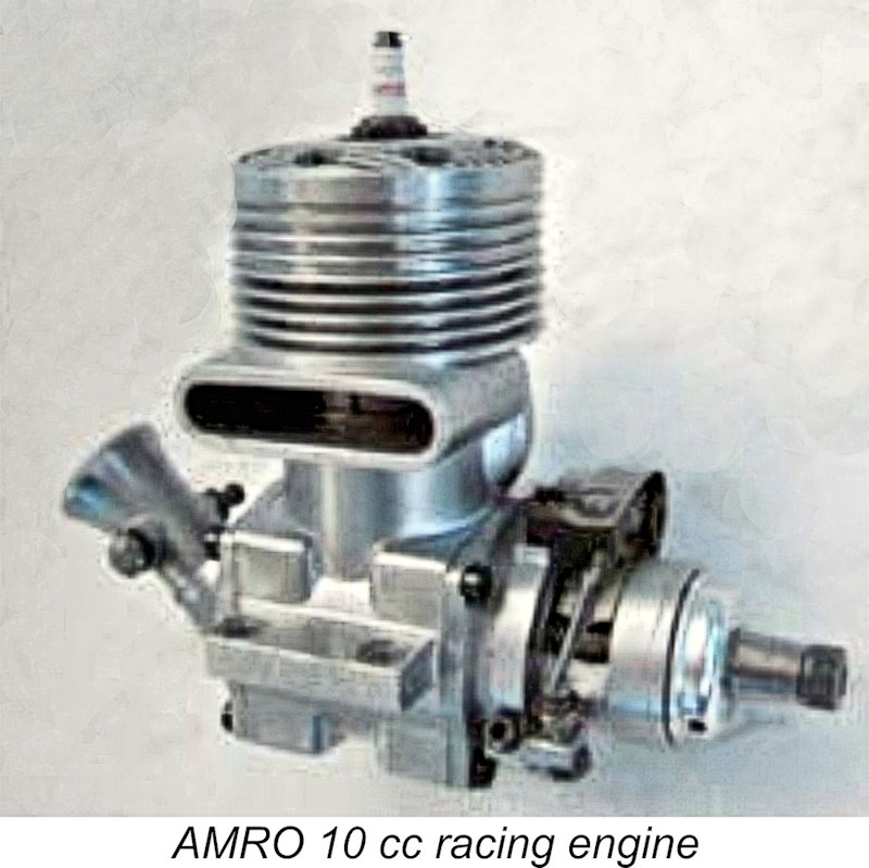
For more information on Penna, please visit the outstanding Onthewire website through the link provided. 1954 – AMRO 10 cc – made in Wichtrach near Bern, Switzerland by FRIRO AG, a precision engineering company owned by The engine’s name was derived from those of its creators AMrein and ROlli. It was virtually an exact copy of the Dooling 61, more or less matching the performance of the original as well as its quality. A few examples were produced with flutter valves in place of the usual disc rear rotary valve, but these units failed to match the performance of the disc-valve models. The AMRO 10 was produced in very small numbers to very high standards until around 1958, at which point Otto Amrein withdrew from the venture after some 40 examples had been produced. Between 20 and 30 more examples were produced by FRIRO under their own name, with the final batch being manufactured in around 1968. The engine enjoyed some success in European tether car competition. Please read the outstanding linked article at the wonderful Onthewire website for much more information.
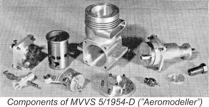
1954 – Letmo 5 – basically a production version of the MVVS 5/1954-D produced in small numbers by Josef Pfeffer’s Letmo workshop with which MVVS boss Zdeněk Husička had long been associated before becoming the inaugural Director of MVVS. Noted Czech speed flier and MVVS employee Josef Sladký reportedly had some involvement with this initiative.
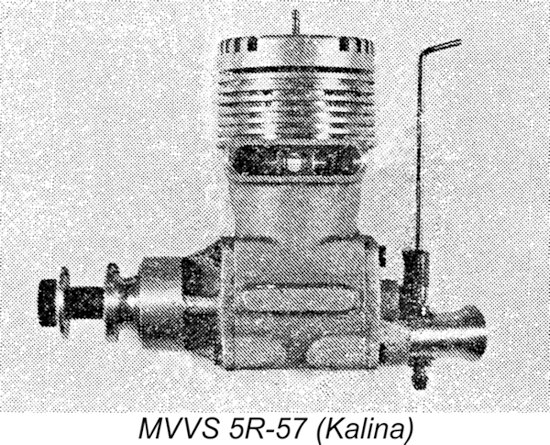
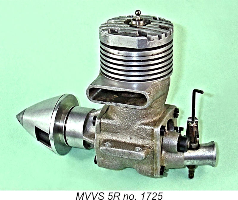
The 5R-57 variant was individually built in very small numbers for the use of recognized Czech experts. An example was used by MVVS employee Bohumil Studený to break the world Class II (5 cc) speed record at 243.96 km/hr (151.6 MPH) in September 1957. Pretty good going on two lines ...........
Although it never won another international championship, the engine remained highly competitive right up to 1961, finishing second at that year’s Criterium of Aces meeting. Around 2,000 examples ended up being produced, finding their way into the hands of many modellers from around the world.
In 1961, the S-1 was superseded by the FRV MOKI S-2 model which abandoned the Dooling design. This latter model was used by Imre Tóth to win the 1961 Criterium of Aces meeting – the first major international competition run under the new FAI straight-fuel requirement.
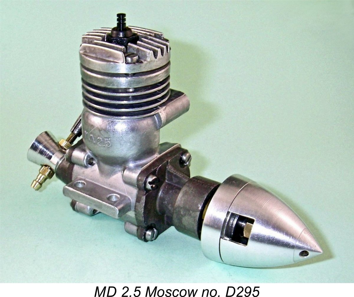
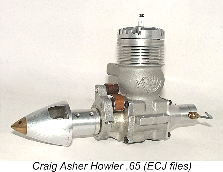
1959 – Boudník 10 – made in small numbers by Vladislav Boudník of Czechoslovakia (as the Czech Republic was then). Clearly influenced very strongly by the design of the Dooling 61. Bore and stroke were 25 mm and 20 mm respectively for a displacement of 9.82 cc. Weight was a very substantial 520 gm (18.34 ounces). Unfortunately I have no other information to share. 1960 – MD-2.5 Moscow – manufactured at Production ended in 1962 when the Moscow was supplanted by the much-improved Super Tigre-based MD-2.5 Meteor. As a result, 1960 – Howler .15 and .65 - these rear drum valve engines featuring the Dooling-inspired bulge bypass were designed by Craig Asher of Cincinnati, Ohio and marketed for the most part in kit form by World Engines. Both .15 cuin. and .65 cuin. Howler models were available, each size being built from the kits in considerable numbers. The .65 cuin. model was made available in both spark and glow-plug configurations.
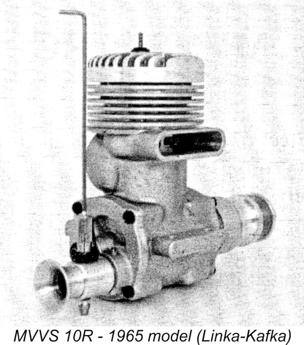
The 5R enjoyed great success as a tethered hydroplane powerplant, establishing a number of records in the process. The 5R's success culminated in 1969 with J. Šustr's establishment of a new European record 1964 – MVVS 10R – basically a 10 cc version of the MVVS 5R introduced at the same time. It was produced in two distinct versions, the second and last of these appearing in 1965. This gave it the distinction of being the last Dooling-based model ever to be introduced by a commercial manufacturer. This listing is doubtless incomplete, but I believe it to be sufficiently comprehensive to make the point regarding the widespread influence of the Dooling "bulge bypass" design concept. There were also a surprising number of Dooling-influenced one-off “specials” constructed by talented individuals for their own use and that of their friends. Space does not permit a review of all such non-commercial units which I’ve come across during my ramblings through the wonderful world of model engines. Conclusion I hope that the above account has convinced you that the Dooling 29 was every bit as much of a trend-setter as its 61 big brother had been a few years earlier. It remained at the top of the 5 cc performance lists for a full ten years or more – no small achievement at a time when model racing engine design was in such a state of constant development. In my mind and in those of many others, the name Dooling will always be synonymous with quality, performance and design leadership! __________________________ Article © Adrian C. Duncan, Coquitlam, British Columbia, Canada First published April 2025
|
|||
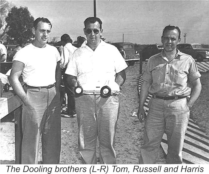 Elsewhere on this website, I’ve traced the history of the three Dooling brothers of Los Angeles, California from their pioneering involvement in the sport of model car racing up to the point at which their iconic
 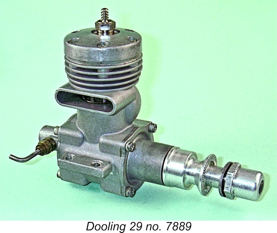 The development of this model unquestionably reflected the changing times. By 1949 the model car racing market had apparently reached its peak and was already showing early signs of entering the steady decline which would see it effectively reduced to “cult” status by the mid-1950’s.
 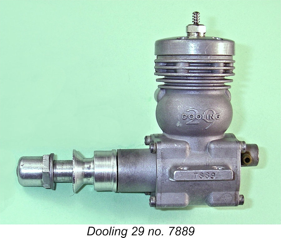 The design of the Dooling 29 reflected all of the trends discussed above. While it generally mirrored the layout of the Dooling 61 with its bulge bypass, disc valve induction and twin ball-race shaft, the new 29 which appeared in 1949 was designed exclusively for glow-plug operation. Moreover, as supplied it was set up for model aircraft use. It’s apparent from this that the makers envisioned the engine being used primarily in aero service - certainly, their advertising reflected this view very strongly. Given the already-visible writing on the wall for the car racing side of the modelling hobby in economic terms, this is scarcely surprising.
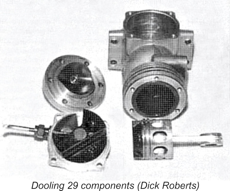 This system has several positive attributes. It minimizes the crankcase volume, thus increasing base pumping efficiency, while also creating a very direct pathway for mixture to reach the transfer ports from the main crankcase. It allows for the provision of transfer ports having a very large total area, particularly when used with a large bore. In addition, it ensures the passage of large volumes of cool incoming mixture through the piston interior, thus promoting improved piston cooling along with excellent wrist pin lubrication. It also results in a lighter piston, thus reducing reciprocating weight. Finally, the presence of the large piston skirt ports ensures an excellent and very direct supply of cool lubricant to the cylinder wall on the transfer side.
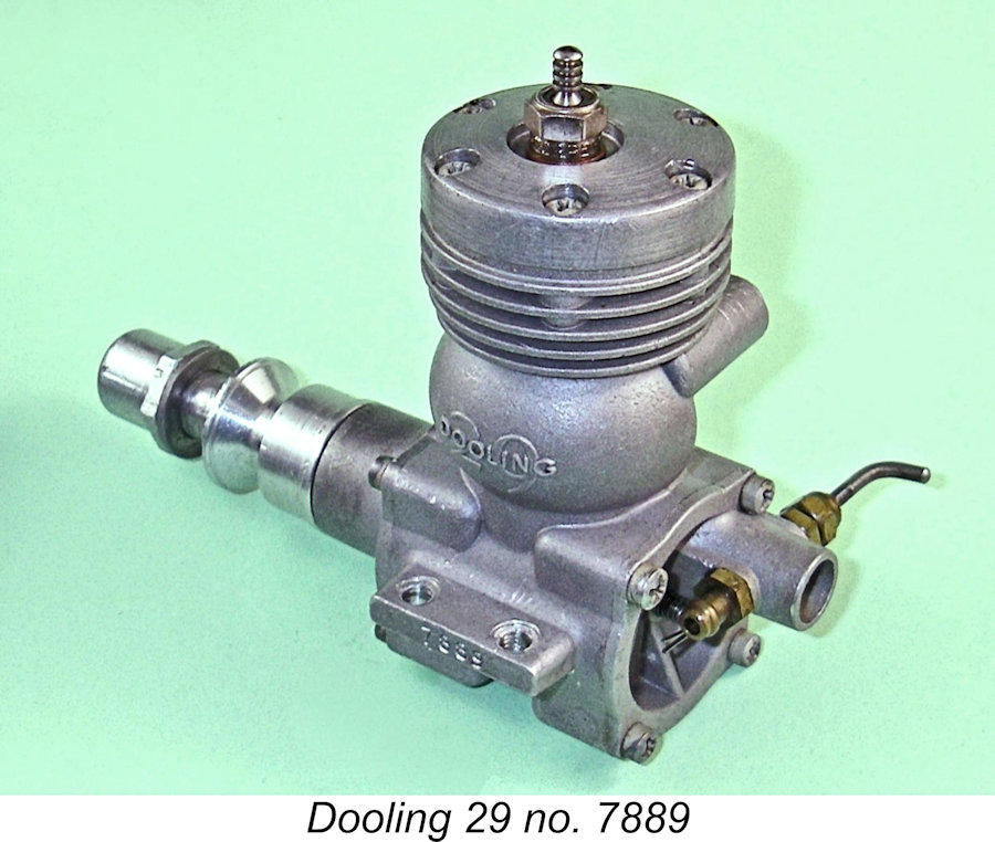 A noteworthy innovation was the use of a plastic material for the heavily-counterbalanced rear disc which controlled induction. This material was far more durable in service than the more commonly-used aluminium alloy. In the original model released in 1949, the disc mounting pin was staked in place. However, the disc was soon provided with a spring-loaded pin intended to maintain disc-backplate contact even when the engine was not running. Engine no. 1977 exhibits this change, indicating that it took place quite early in the production sequence.
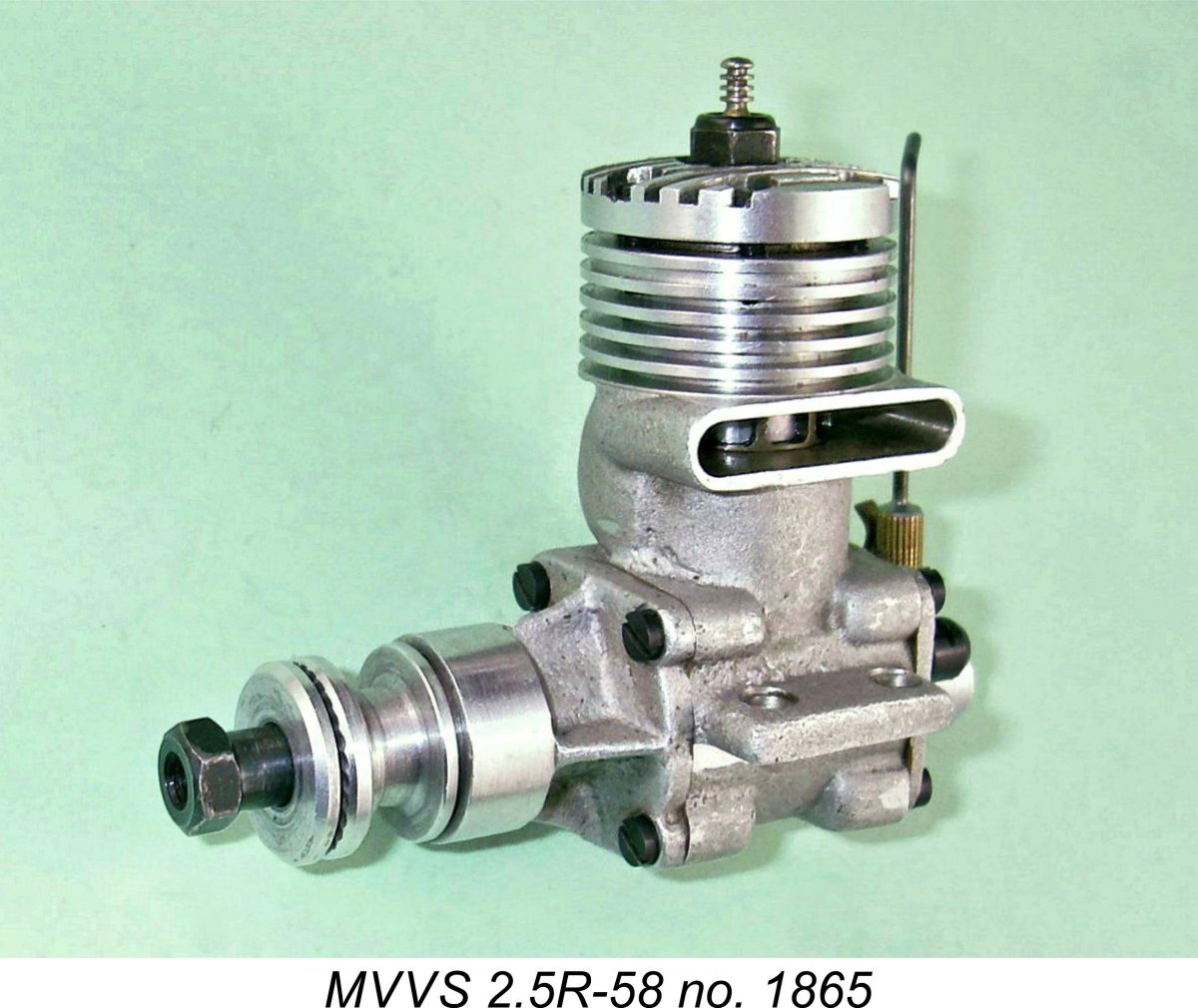 One previously-mentioned issue that deserves some discussion here is the orientation of the exhaust stack on the Dooling engines. In my separate article on the
 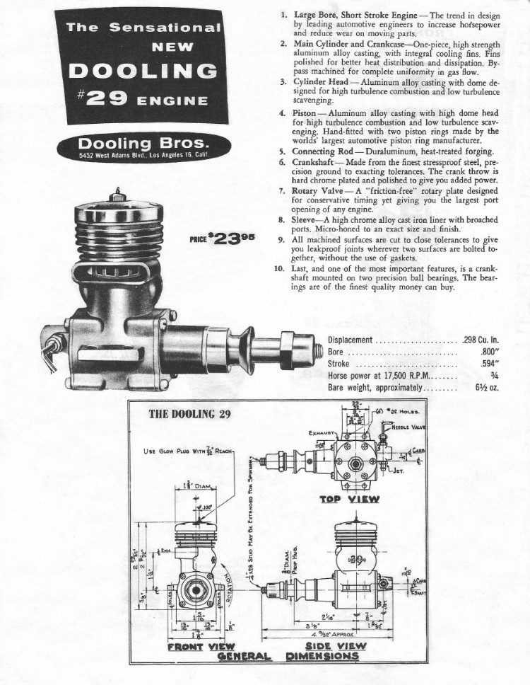 The Dooling brothers advertised their new offering quite extensively in the modelling media of the day. A typical advertisement is seen at the left. Their advertising focused upon the engine’s most significant design attributes and material specification. An output of 0.75 BHP @ 17,500 RPM was claimed – an unprecedented level of performance for a .29 cuin. (5 cc) engine at the time.
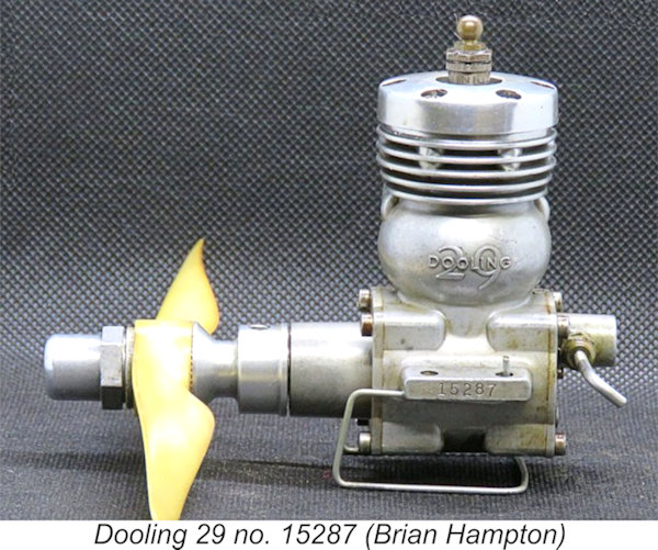 As a result of its enthusiastic adoption, the Dooling 29 was manufactured in relatively large numbers by racing engine standards. Confirmed serial numbers of my direct personal acquaintance are spread uniformly over a range from a low of 1788 all the way up to a high of 16,497, implying the production of some 17,000 units at least. This has had the happy result of ensuring that examples of the engine in as-new or excellent condition remain relatively available today, although such examples still command relatively high prices given the engine’s legendary status.
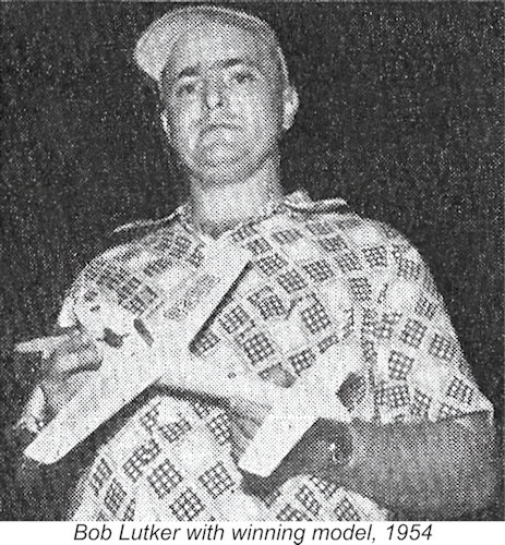 The 1954 World Control-Line Speed Championship meeting held at The Hague, Netherlands provided a perfect snapshot of the Dooling 29’s dominance at this time, even after production had ceased. This meeting was held prior to the 1955 adoption of the 2.5 cc displacement category for all FAI power modelling events other than Control-Line Aerobatics and R/C. In 1954 the FAI had decreed that the World Control-Line Speed Championship would be contested in the 5 cc displacement category. Somewhat unusually, the Speed events were held indoors in the very large Houtrust Hall at The Hague.
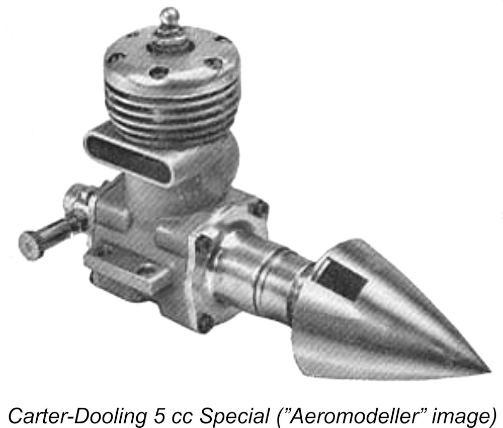 Carter replaced most of the engine’s components with items of his own making. The engine received Fred’s own replacement front main bearing plate, cylinder liner, single-ring piston, cylinder head and backplate, along with a new disc valve made from Tufnol. About the only original Dooling parts left were the main casting, the conrod and the crankshaft!
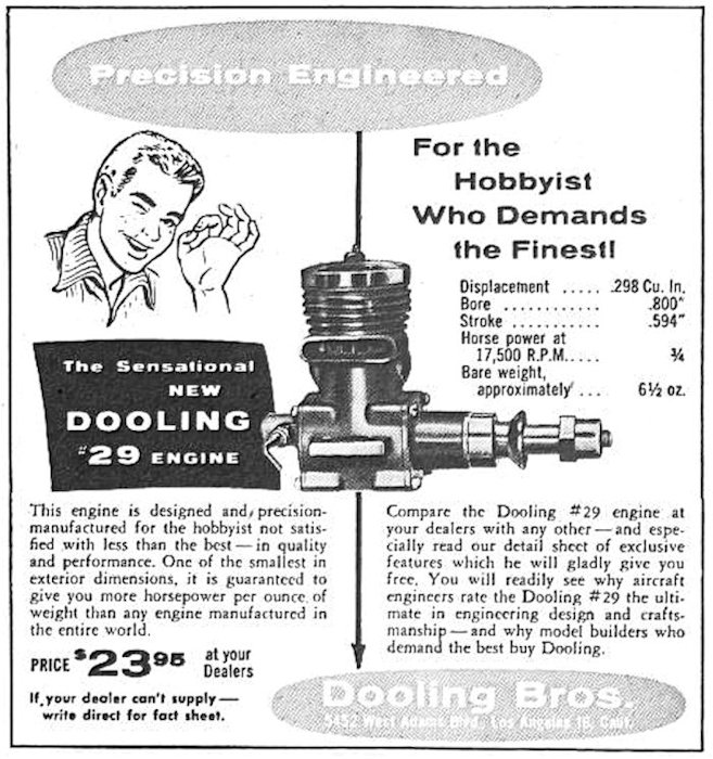 Despite the fact that production of the Dooling 29 had ceased in 1953, the engine continued to hold a dominant position in the .29 cuin. (5 cc) competition classes for which it had been designed, consequently remaining in high demand. This continued dominance can’t have escaped the attention of the Dooling brothers. In 1957 they took the unusual step of resuming production of their 8-year-old design, which was still the one to beat even after the passage of all that time. The Dooling 29 was the sole model to be resurrected – the future of the fabled Dooling 61 was left in the hands of Bruce Underwood and his
 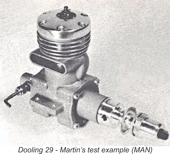 This particular test has a fascination all its own, because it is far more than a simple review of a particular engine. Martin began by making the insightful observation that the better an engine is at doing one particular job (in this case going fast), the worse it will be at doing other jobs. He commented that the Dooling was the very best at going fast, but among the very worst for going slow!
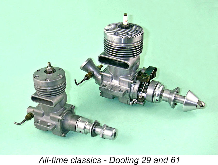 When the Dooling 61 first appeared in 1947, it took the racing engine scene by storm, setting a new performance standard for 10 cc engines more or less overnight. In response, most competing model racing engine designers initially tried to improve what they had or develop new models of their own design inspiration.
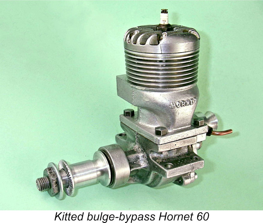
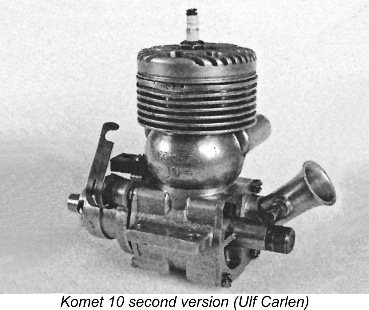 1950 – Komet 10 – produced by the Johansson brothers of Västerås, Sweden. This model displayed a high level of Dooling influence, to the point that many original Dooling 61 parts would fit into the Komet. The Swedish copy appeared in two variants displaying minor differences in the main casting, but was otherwise little changed throughout its intermittent nine-year production life.
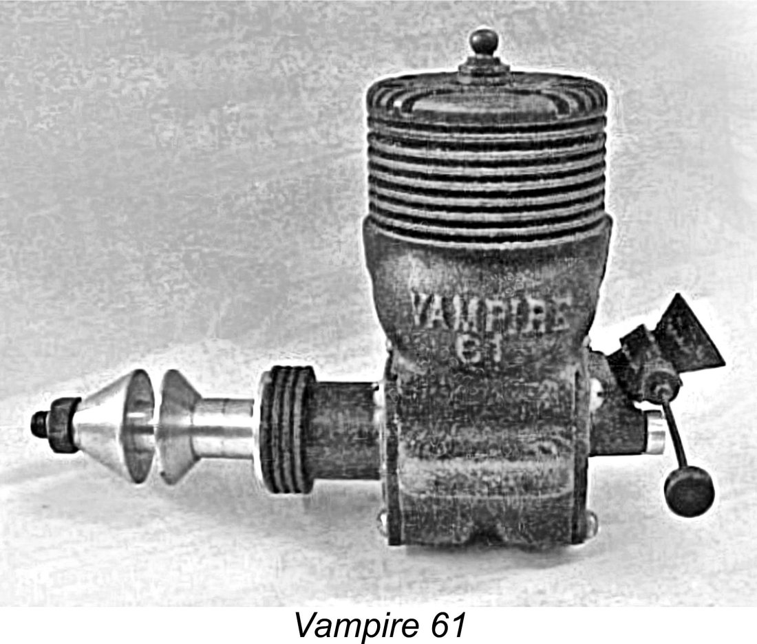
 1951 –
 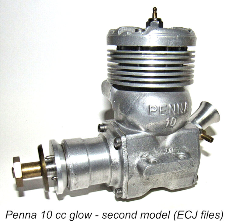 1951 -
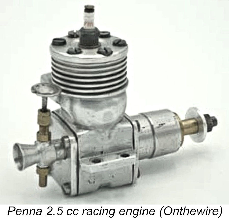
 1954 –
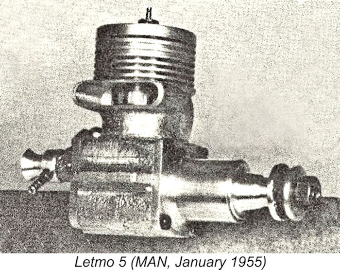
 1957 –
  1957 –
 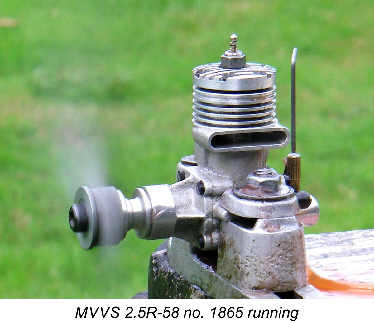 1958 –
 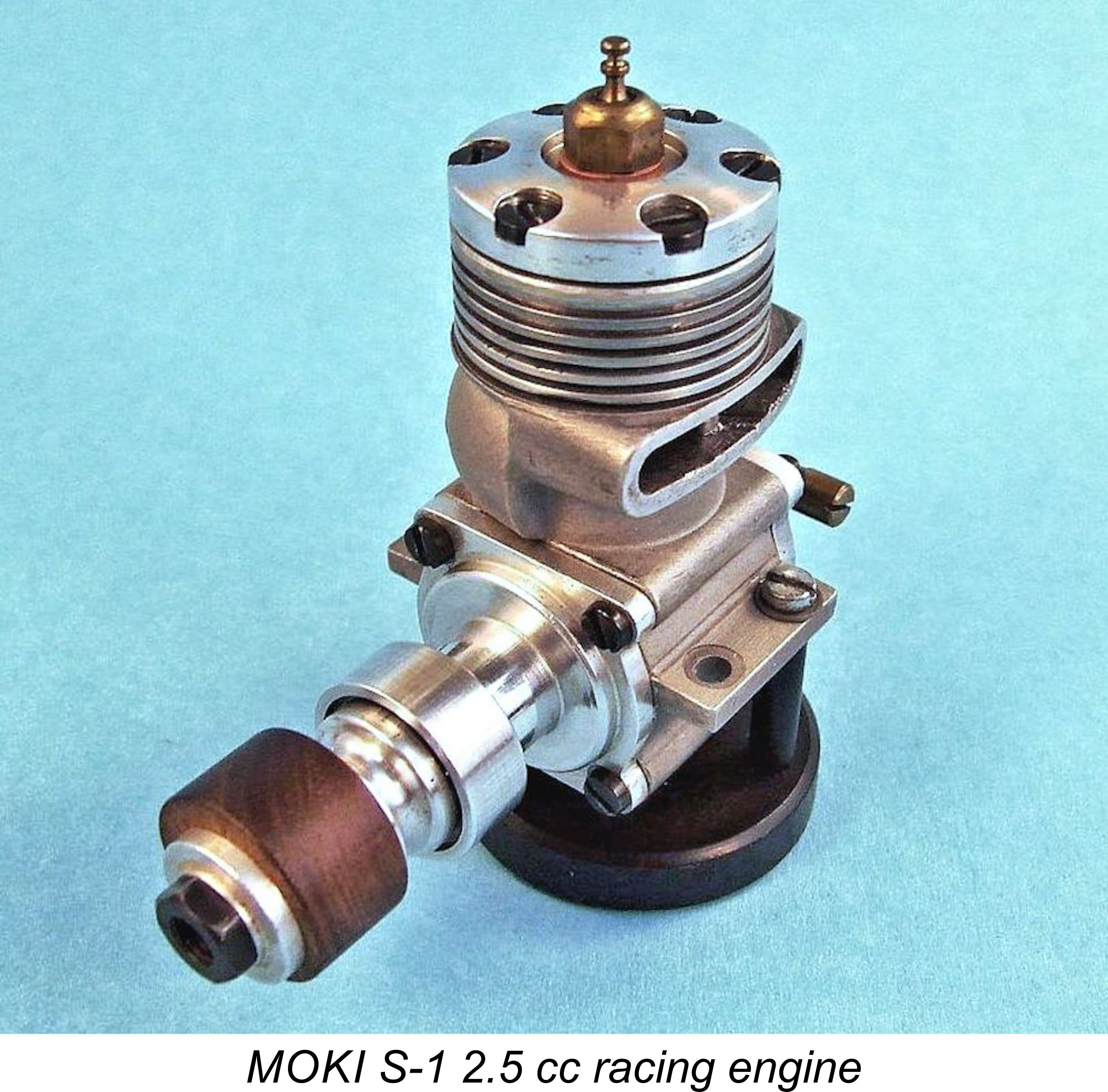 1958 –
  1959 –
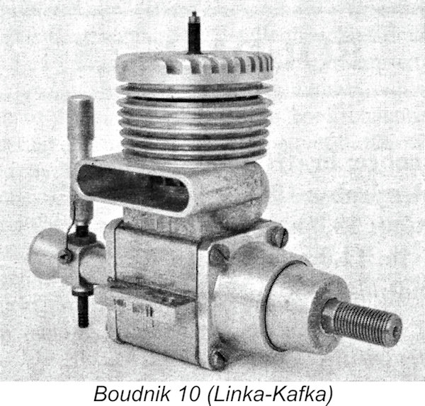
 of 157 km/hr in the Class A2 category for water-screw hydroplanes. This engine thus had the honor of being the last of the Dooling-based engines to enjoy international contest success in any category.
| |