
|
|
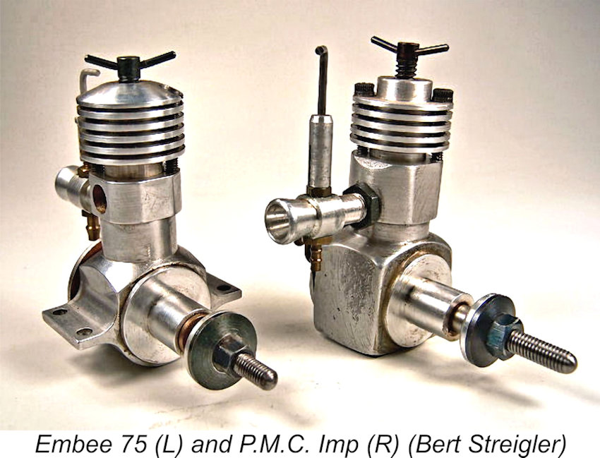
The Embee 75 and P.M.C. Imp Diesels
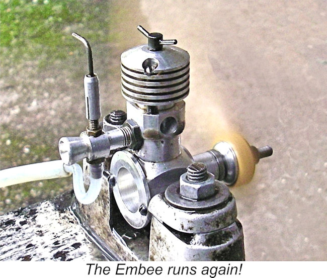
This is a pity, because while these small diesels undoubtedly do have a few warts, they are actually very nice little engines which start easily and run well. The Embee 75 in particular is quite well-made and nicely finished. They don’t develop a lot of power, but they are ideal powerplants for small free flight sport or scale models. They are also very suitable for beginners just learning how to handle a diesel. Finally, they’re just plain fun to run! In what follows, I’ll do my best to shed some light upon the true qualities of these engines as well as the background to their production. In doing so, I’ll be drawing heavily upon the earlier efforts of my late mate Ron Chernich, whose December 2005 article on the P.M.C. Imp may be found on his frozen but still accessible “Model Engine News” (MEN) website. Background and Production History
It turned out that the individuals responsible for the Embee were Peter A. Moore and D. J. Bailey. The engines were distributed by Performance Kits of Sandy in Bedfordshire. The owner of Performance Kits, the late O. F. W. “Peter” Fisher, was thus unusually well placed to have first-hand knowledge of the Embee venture. He devoted several paragraphs to the progression of this series in his well-known 1977 book “Collector’s Guide to Model Aero Engines”.
By this time, Moore had expanded his range of available mufflers to include extraction-type silencers for side-stack engines. His new offerings were described and illustrated in an article on silencer developments which appeared in the March 1965 issue of "Aeromodeller". My grateful thanks to Gordon Beeby for drawing my attention to this aspect of Peter Moore's activities. In the mid-1960’s Moore persuaded his partner that the Moore & Bailey company should begin to make moves towards entry into the model engine manufacturing business. Bailey appears to have been somewhat less enthusiastic, but nonetheless went along with the idea. After a development period of some two years, the original Embee 75 which forms my central subject here appeared in early 1968. It became known as the Embee 75 Mk. I model. It was a prototype of this model which was sent to Peter Chinn for his evaluation. In his March 1968 article, Chinn observed that entirely new British engines were "...somewhat rare these days". He continued by noting that the Embee was very much a throw-back to the long-stroke side-port diesels of the early post-war period – the Mills diesels came immediately to his mind. He felt that the Embee might well find ready acceptance among the many modellers who regretted the 1964 termination of Mills production in England. Finally, he reported that the selling price of the Embee would be a very reasonable £3 10s (£3.50).
It appears that the version of the engine described by Chinn was an early prototype example. He was quick to get his hands on an example of the production version for testing. His report appeared in the June 1968 issue of “Aeromodeller”. More of that test below in its place. Oddly enough, the manufacturers of the Embee seem to have put little or no effort into the promotion of their product. Neither Ron Chernich nor my valued mate Gordon Beeby were able to find a single manufacturer’s advertisement for the engine. Reading between the lines, I suspect that Moore’s partner Bailey was perhaps a little lukewarm towards the company’s participation in the model engine field, hence being unwilling to invest in its promotion.
Fisher tells us that in 1969 the company ended model engine manufacture, returning to making machinery for fabric production. This clearly didn’t sit well with Peter Moore, who left the partnership in 1969 to establish his own manufacturing facility at 72 Fairfax Road in the City of Leicester. His express purpose in doing so was to continue the production of model engines. He traded from this point onwards as P&M Engineering, although he evidently retained the right to use of the Embee name for his engines.
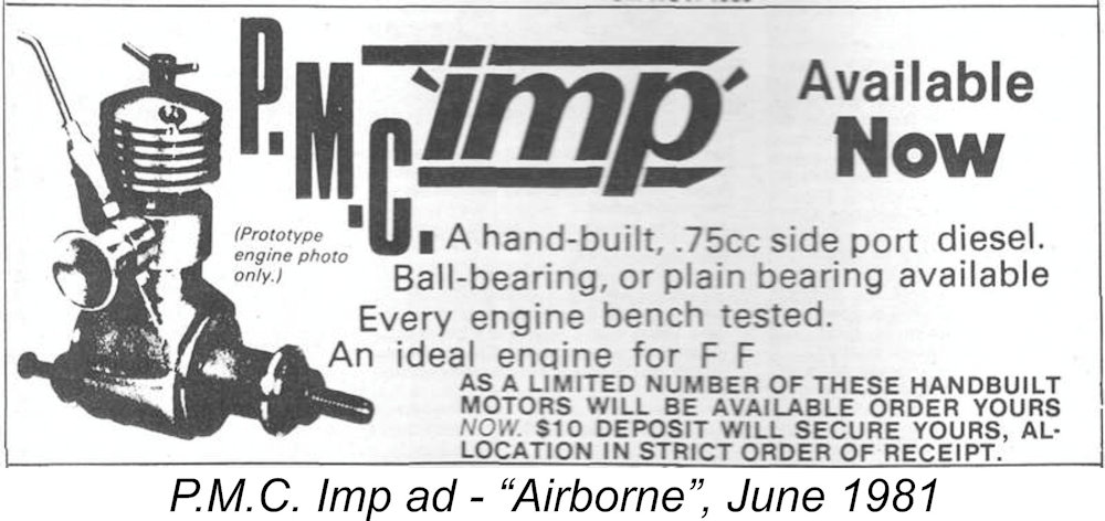
During this period, continued efforts were apparently made to develop an export market for the Embee 75. My valued mate Gordon Beeby found that an American company called Hobby Hideaway of Delavan, Illinois advertised the Embee 75 in "American Aircraft Modeler" in every issue between January 1971 and December 1971, also mentioning the Embee one last time in their May 1972 advertisement in the same periodical. They also advertised the Embee in 1971 in the September/October and November issues of "Model Builder". The proprietor of Hobby Hideaway was the late David Shipton, who seems to have been a well-respected member of the modelling community based on comments in various forums. He also ran a museum at the same site as his mail order business. In addition, Moore broadened his development activities considerably. By May 1972, Peter Chinn was able to report the availability of several additional Embee models, including a crankshaft front rotary valve version of the Embee 75 as well as a 2.5 cc ball-race diesel and an opposed twin based on two Embee 75 units geared together. None of these designs appears to have been produced in significant quantities. More of them below in their place ……….. After 1972, no more was heard of the venture in the modelling media until 1980, although production presumably continued at some level. In 1979, Moore adopted the trade-name P.M.C. and amended the former Embee design considerably to come up with a new variant which he designated the P.M.C. Imp, Unlike the Embee before it, the Imp was announced through the placement of an advertisement in the October 1980 issue of “Aeromodeller”. Interestingly enough, the Imp was also promoted in Australia through the inclusion of an identically-worded advertisement in the June 1981 issue of the Aussie modelling magazine “Airborne”. However, the engine doesn’t appear to have remained in production beyond 1982.
Unfortunately, my mate Ron Chernich evidently mis-read this reference when writing about the Embee and P.M.C. Imp models in 2005. He took Chinn’s statement as implying that the P.M.C. Imp was made by Peter Moore in the Isle of Man, publishing this location as an established fact. Later commentators, including Ted Sladden, seem to have accepted this statement without checking its source. In reality, a careful reading of Chinn’s somewhat ambiguously-worded reference to the Isle of Man shows that it related solely to the activities of John K. Moore. The idea that Peter Moore would have relocated to the Isle of Man makes very little sense. Now, having set out what little seems to be known about the background to this series of engines, it’s time to take a closer look at the engines themselves. Variants of the Embee and its Relatives
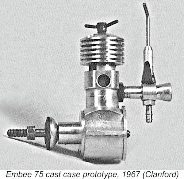
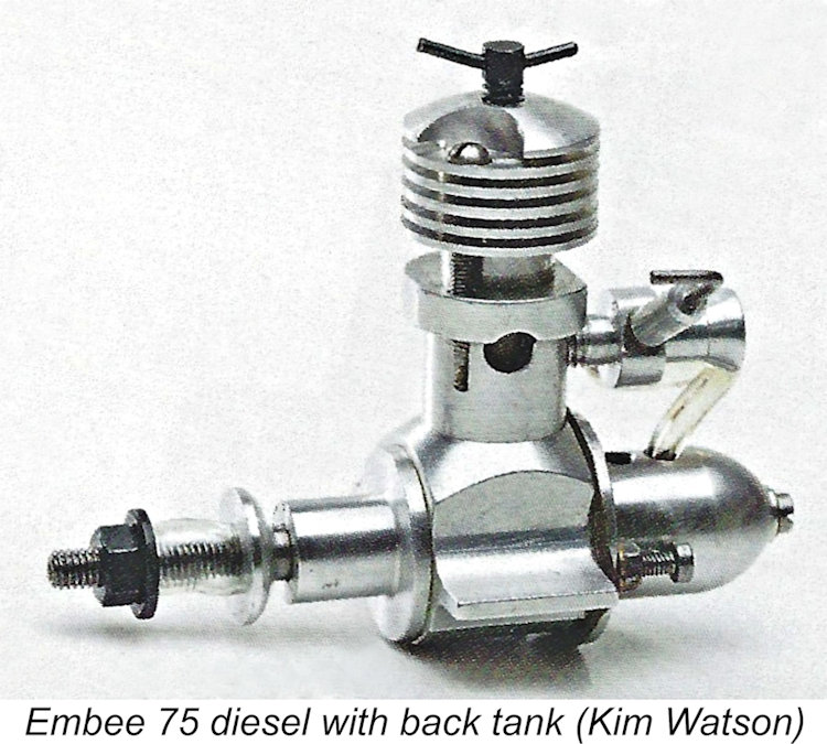
The form with which the Embee is most commonly encountered is the familiar Mills-influenced sideport model illustrated here. However, a review of available pictorial sources such as Mike Clanford’s well-known “A-Z” book and Ted Sladden’s highly-recommended book on British model aero engines reveals that Peter Moore experimented with a surprisingly wide variety of Although Mike Clanford’s book is an invaluable source of pictorial information for which he deserves great credit, he seems to have done very little original research into the history of the engines depicted, tending instead to simply take the unsubstantiated statements of others at face value without checking. As a result, it’s necessary to approach his comments on various engines with a considerable degree of caution. This being the case, we have only his unsubstantiated word to inform us that the very first Embee Further prototypes appeared over the next few years. The first Embee 75 models were constructed around a somewhat porous sand-cast crankcase, but a decision was soon made to change to a fully-machined barstock component. This variant was further developed to the point in early 1968 at which Messrs. Moore and Bailey felt justified in sending one of the barstock prototypes to Peter Chinn for his review and comment. It was this engine which prompted Chinn to publish his previously-cited commentaries in March and April 1968. The version of the Embee 75 which finally entered production was a slightly modified version of this prototype. The machining of the case was somewhat altered, while the engine’s height was reduced a little, with a matching 10% reduction in weight. The used of According to Ted Sladden, a variant of this model appeared in 1969 featuring a back tank. However, this may have been another experimental model – in over 40 years of looking, I’ve never Production of the sideport Embee 75 evidently continued at a modest level into 1972. However, things had not stood still in the meantime in terms of development. In the May 1972 issue of “Aeromodeller”’, Peter Chinn’s “Latest Engine News” column The Embee 75-RV has to be one of the best-kept secrets of the British model engine manufacturing industry. The engine was never advertised either by the manufacturer or by the retail trade. I wasn’t even aware of its existence until my good mate Gordon Beeby drew my attention to Chinn’s relevant article. I subsequently found images of this seemingly rare variant in the previously-cited books by Clanford and Sladden.
Chinn also mentioned the “geared twin” units produced by Peter Moore. These too are extremely rare, also being encountered in a bewildering range of different configurations – flat opposed twin, All of the twins were based upon two basically standard Embee 75 engines mounted on a common backplate and geared together at the front, thus taking advantage of the engines’ Perhaps the most unusual Embee variants were the “mock rotary radials”. These featured a dummy three-cylinder “engine” which was mounted on the shaft behind the airscrew and rotated with the prop. This gave the front of the engine the appearance of being a rotary radial powerplant. These mock-ups were of course intended to impart a little extra realism to scale models of subjects such as WW1 fighters which were powered by rotary radial engines. Looking at the layout, the precise balancing of both prop and dummy "engine" would have been at a premium. As we might expect, demand was very low, resulting in very few being made. Now, having quickly surveyed the surprisingly extensive range of models produced under the Embee name, it’s time to take a closer look at the Embee variant which will be most familiar to model engine enthusiasts – the original barstock sideport Embee 75 diesel. The Embee 75 – Description
A unique feature of the Embee was the construction of its crankcase/main bearing unit. What appeared to be an integrally-machined main bearing housing was in reality a separate turning which was pressed into the bore of the crankcase and secured with Araldite, a well-known English two-part epoxy of unusual strength. No fasteners were involved in this assembly. This may sound a bit Mickey Mouse, but I’ve seen no evidence to suggest that the front housings secured in this way had any tendency to work loose. There’s some ambiguity with respect to the true displacement of the Embee. At the outset, the makers apparently cited bore and stroke dimensions of 0.313 in. (7.95 mm) and 0.510 in. (12.95 mm) respectively for a true displacement of 0.643 cc, considerably lower than the 0.75 cc figure implied in the engine’s name. Fair enough, one might think, but Peter Chinn’s test example (see below) had a measured stroke of 0.475 in. (12.06 mm) to go along with the 0.313 in. (7.95 mm) bore, giving his engine a displacement of 0.599 cc. By 1972, Peter Moore had reportedly revised the claimed stroke figure to a nominal 0.480 in. (12.19 mm), seemingly confirming Chinn’s earlier figure. For all practical purposes, the Embee 75 may be viewed as a 0.6 cc engine in defiance of its numerical designation. It weighed in at 2.79 ounces (79 gm).
The leaded steel cylinder liner featured two pairs of drilled exhaust ports positioned one pair to each side. These ports discharged through circular openings in the upper crankcase unit. The transfer ports were also a pair of drilled holes located at the front of the cylinder. They were located well down the bore from the exhausts, necessitating the use of a step in the piston crown to provide an adequate transfer period and direct the incoming mixture upwards. The transfer ports were fed by a bypass passage created simply by machining a flat into the front outer wall of the lower cylinder. The Meehanite cast iron piston drove the crankshaft through an alloy rod of typical British “dog bone” pattern. The crankweb on the one-piece steel crankshaft was a plain disc with no counterbalance. The 0.250 in. dia. main journal was unusually large for an engine of this displacement. It was an excellent fit in its plain bearing. At the front, the aluminium alloy prop driver was mounted on a self-locking taper at the front of the shaft. Here we encounter what I consider to be a weakness in the engine’s design. On many examples (including my own), the distance between the rear of the prop driver and the front of the main bearing housing is The remedy is to make a steel or bronze spacer to fit behind the prop driver to take up most of the slack. I wouldn’t recommend running an Embee unless this was done. My illustrated example is fitted with such a spacer, which is visible in the image at the right. At the rear, the screw-in venturi tube was retained by a lock-nut. A conventional spraybar was used. The needle valve was provided with a split thimble for setting retention. The backplate was secured by two machine screws rather than being a screw-in component of the more typical type. This allowed the engine to be radially mounted, provided access to the screw heads from behind the front bulkhead could be arranged. That said, the engine as supplied was set up for beam mounting. Overall, it’s fair to say that the Embee 75 was a very nicely-made little engine. The finish was excellent and all fits were first class. Well and good, but how did it perform? Let’s find out!! The Embee .75 on Test
Chinn gave the bore and stroke dimensions of his test engine as 0.475 in. (12.06 mm) and 0.313 in. (7.95 mm) respectively, giving his engine a displacement of 0.599 cc. He pointed out that this was considerably less than the 0.75 cc implied by the engine’s name. Chinn reported that the Embee was “quite easy” to start. He commented that a port prime was unnecessary – all that was required was two or three choked turns to fill the fuel line and introduce a little fuel into the crankcase. He found starting to be at its best on 8 in. dia. props, which actually suited the engine quite well in operational terms. On smaller loads the engine had a tendency to become a bit of a “finger biter”.
Chinn reported a peak output of 0.032 BHP @ 8,500 RPM. He considered a 7x4 Top Flite wood prop to be ideal for use with this engine. The Embee turned this prop at 7,800 RPM on the bench, which should rise to the peaking speed in the air. Overall, Chinn found the Embee 75 to be an ideal beginner’s diesel, particularly well-suited to “fly for fun” free flight models. He also felt that vintage enthusiasts might well view the engine favorably as “a near authentic powerplant for an early post-war type small free flight power model design”. My own experiences with the Embee have been uniformly positive. I’ve owned two examples of the engine, one of which I still have. My original example (acquired way back in 1980) was New in Box, but I traded it on years ago after confirming that it started and ran very well, albeit without developing much power.
While examining the engine prior to the test, I noted that the gap between the prop driver and the front of the main bearing housing was sufficiently large that the shaft could set back to the point where the crankpin made contact with the backplate. Not a good situation! As noted earlier, I resolved this problem by making a steel spacer ring of suitable thickness to fit behind the prop driver. In terms of the engine’s handling, I can endorse Chinn’s comments unreservedly – the Embee is an extremely easy starter, requiring only a single choked flick on a full fuel line to get enough fuel into the case for an almost immediate start – often on the first flick after choking. Very reminiscent of a Mills, in fact! Priming the engine is counter-productive – it simply floods the cylinder. With the very small ports provided, clearing a flood takes some time.
Once started, the engine runs extremely smoothly, with minimal vibration despite the very long stroke. Noise levels are notably restrained, as we might expect given the use of very small round holes to serve as exhaust ports. I first tried the Embee on a BY&O 8x3 wood prop. The engine spun this load at a smooth and steady 6,000 RPM. On an APC 7x4, the engine got up to 7,800 RPM – around 0.030 BHP at that speed. This seems to confirm the validity of both Chinn’s test figures and his recommendation that a 7x4 prop would probably be ideal for use with this engine. Overall, I was quite impressed with the Embee. It was certainly no powerhouse, but presented itself as a very well-made, nicely-finished, docile, easy-starting and smooth-running little sport powerplant. The P.M.C. Imp
The manufacturer was not identified specifically, but it has always been generally accepted that it was Peter Moore – the maker’s P.M.C. initials are completely consistent with this identification. Distribution was now said to be in the hands of a company called Radio Control Hobbies of 243 Cheam Common Road, Worcester Park, Surrey. The price was stated to be £17 each or £32 for two. Interestingly enough, the Imp also put in an appearance in a similarly-worded advertisement placed in the June 1981 issue of the Australian modelling magazine “Airborne”, as mentioned earlier. The engine doesn't appear to have caught on in Australia. Gordon Beeby drew my attention to a comment made by Stu Richmond in an article entitled "Ramblin' in Oz" which appeared in the October 1988 issue of "Model Builder". Stu recalled purchasing three P.M.C. Imps from Jordal Hobbies in Sydney. Given the date, these must surely have been New Old Stock which the shop was happy to unload.
When production versions of the Imp began to appear, they proved to lack the fine finish and attention to detail which had been evident in the Embee 75. The impression was that they were rather hurriedly assembled, probably using left-over Embee 75 components for the most part with inadequate attention being paid to the optimal matching of parts. Bore and stroke dimensions were essentially unchanged. Ron Chernich reported bore and stroke dimensions of 0.314 in. (7.97 mm) and 0.488 in. (12.395 mm) respectively for an identical nominal displacement of 0.600 cc.
The cylinder appeared to be a standard Embee 75 component which was axially oriented at 90 degrees anti-clockwise (viewed from above) from the Embee configuration, bringing the induction ports to the right of the engine and the transfer ports to the left. The cylinder continued to feature two pairs of exhaust ports, but the front pair were blanked off by the upper crankcase. On the early examples of the Imp, the rear exhaust opening was provided with a pressed-in stub exhaust pipe, but this was omitted on later units. A few later examples also included a front-facing opening for the front exhaust ports. The shape of the cooling jacket also varied over time, as did the machining of the crankcase. A few examples even reverted to a rear intake location. The detail changes were so many and so frequent that it's really hard to say that any particular variant was the "standard" Imp! The maker seems to have used whatever came to hand at any given time, with varying attention paid to the machining steps.
All other components of the Imp appeared to be identical to those used in the Embee 75. However, it bears repeating that the level of quality control apparent in the Imp fell well short of that displayed in the Embee. Motor Boy International member Ken Croft Interestingly enough, the P.M.C. Imp was also offered as a single ball-race model – why beats me, because the engine’s performance characteristics were not such as to suggest any real benefit arising from such a feature. Regardless, such engines did exist, as witness the illustrated example from the collection of my late and much-missed mate David Owen. A fine video posted on YouTube by my friend Derek Butler of Australia shows one of these ball-race engines running very nicely! My audio-tach suggests that it manages around 6,500 RPM on the 7x4 Taipan prop that Derek was using. Conclusion It will have become apparent from reading this article that Peter A. Moore was a very prolific maker of model diesel engines – far more so than he has generally been given credit for. His best-known product was undoubtedly the oddly-named Embee 75 sideport diesel of 0.6 cc displacement, but a number of his less-familiar designs also appear to have possessed considerable merit. I hope I’ve convinced you that the Embee 75 in particular is a far better engine than popular opinion might suggest. These engines generally sell for very reasonable prices. Anyone acquiring an example will find that they’ve received very good value for money – this is a well-made, sweet-handling and smooth-running little diesel that is a real pleasure to operate! __________________________ Article © Adrian C. Duncan, Coquitlam, British Columbia, Canada First published March 2025
|
 In this article, I’ll examine a couple of low-production English diesels that appear to me to be somewhat under-valued by present-day model engine enthusiasts. I’ll be dealing with the Embee 75 diesel and its successor, the P.M.C. Imp. These engines appear from time to time on eBay and elsewhere, generally selling for prices which reflect a widespread perception among collectors that they have little intrinsic value.
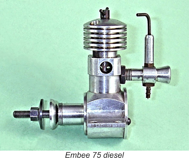 The aeromodelling world first became aware of the introductory member of this series, the Embee 75 diesel, through Peter Chinn's “Latest Engine News” (LEN) column in the March 1968 issue of “Aeromodeller”, in which Chinn announced the release of the engine, citing it as the first new English diesel to appear for some appreciable time. The makers were given as Messrs. Moore & Bailey of Groby, a small community lying a little to the north-west of Leicester in Leicestershire. The business was conducted from an address on Rookery Lane in Groby. The Embee name clearly reflected the initials of the manufacturers.
 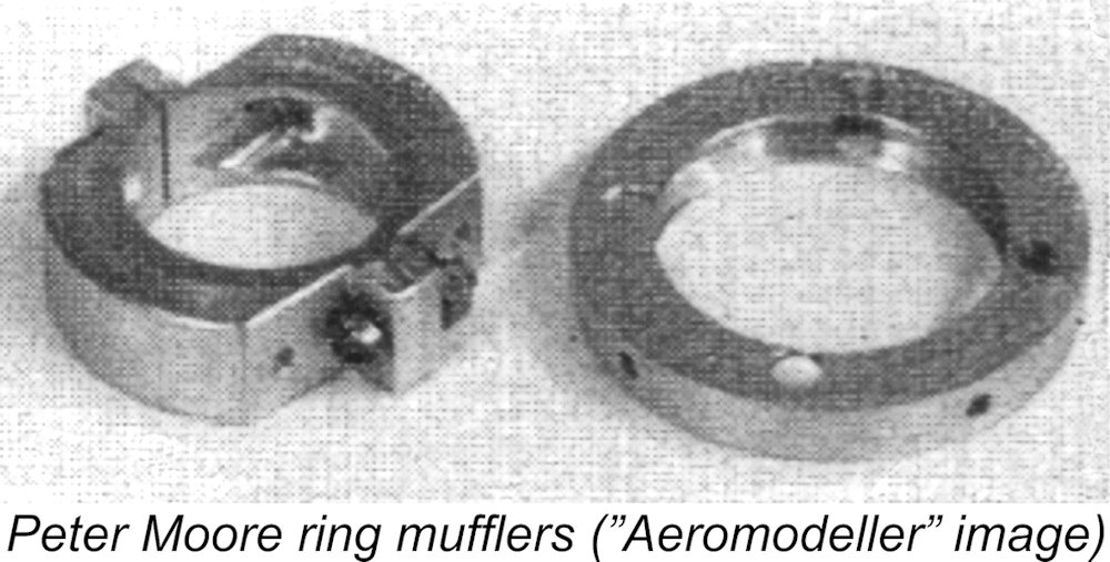 Fisher tells us that the Moore & Bailey partnership was involved primarily with the production of machines for fabric manufacture. Peter Moore seems to have been the driving force behind the entry of the company into the field of model engine production. He appears initially to have entered the model trade on his own account by manufacturing a range of simple ring silencers for engines such as the FROG 249, Rivers 3.5, Oliver and A-M diesels as well as a special unit for the Cox Tee Dee 15. His efforts were noted in an article on silencer developments which appeared in the September 1964 issue of "Aeromodeller". These products were offered under Moore's own name.
 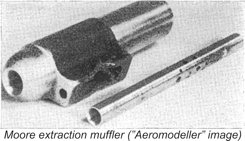 At this stage, Moore appears to have been conducting the silencer business from a location which was distinct from the premises of Moore & Bailey. A placement by Moore in the Trade Classified Ad section of the January 1965 issue of "Aeromodeller" states "Any I/C engine supplied or fitted with silencers or mufflers to suit". Moore's address in connection with this business line was 83 Marfitt Street, Leicester - probably his home address.
 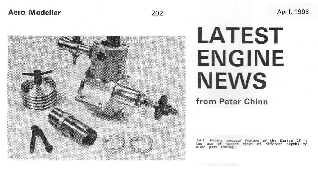 Chinn returned to the Embee in his LEN column for the following month of April 1968. In his article for that month, he provided a few details of the engine’s construction, including a photo of a partially-disassembled example as seen at the left. His report highlighted an unusual feature of the engine, which was supplied with three cylinder spacing rings of different depths (7/64, 1/8, and 9/64 in.). These permitted the user to vary the vertical position of the cylinder ports in relation to the crankcase axis, effectively altering the timing of the engine - a unique and curious feature
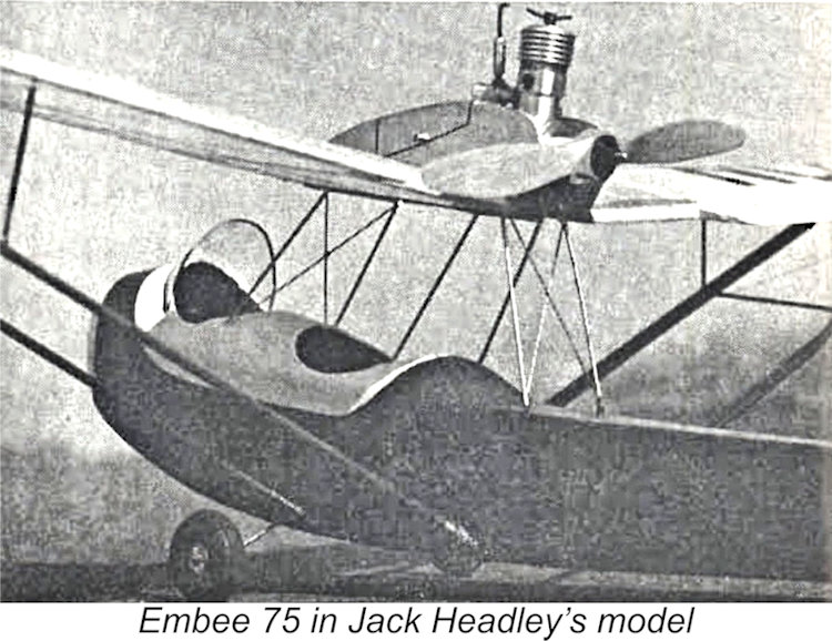 Production by the partnership appears to have continued at a relatively modest level into 1969. The engine did attract some market attention - one example made it all the way to California, USA, where it was used in Jack Headley's scale model of the Curtiss-Wright Junior which was featured in the April 1970 issue of "Aeromodeller".
 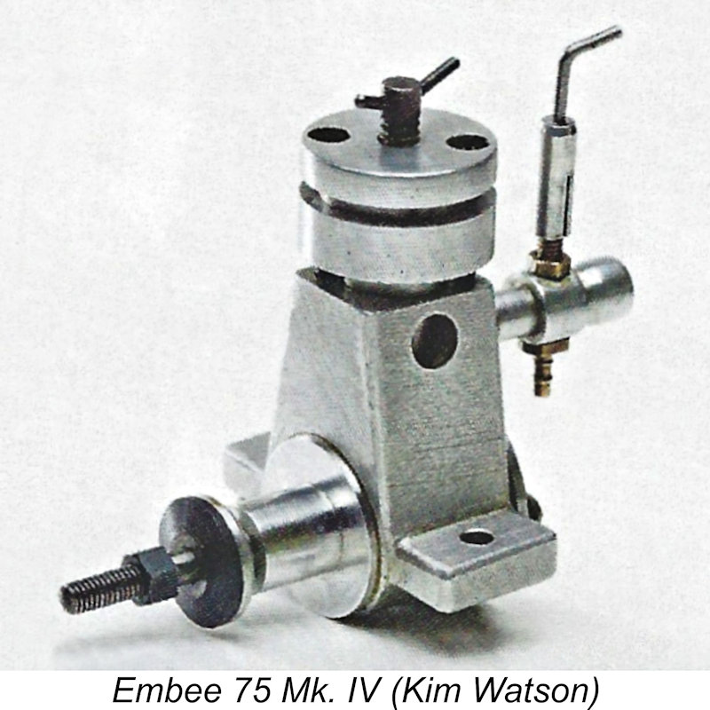 Production of the Embee 75 was evidently resumed at this point, with several variants being produced as the Mk. II, Mk. III and Mk. IV models. The differences were mainly of a detail character. The most unusual variant was the Mk. IV model, which had only a single cooling groove in its otherwise cylindrical cylinder jacket.
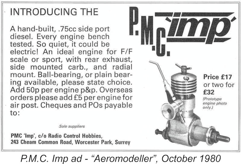
 One matter which should be cleared up here once and for all is the frequent attribution of the 1972 revival of the
 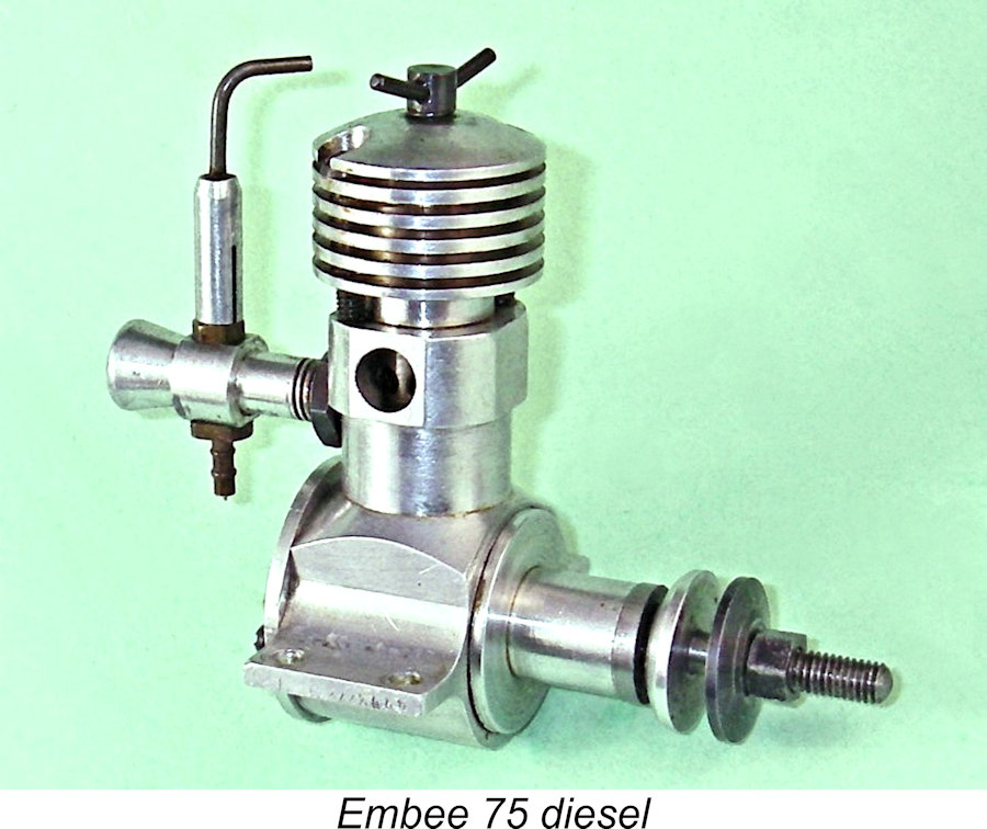 When I began this project, I honestly expected it to be one of my least challenging reviews – after all, how much could I say about two very simple little sideport diesels? However, it turned out that there was a lot more to the work of Embee manufacturer Peter Moore than most engine aficionados realize (including myself before I began researching this article!). Here I’ll summarize the full range of designs developed by Moore before re-directing my focus to his earliest and most prominent offering, the Embee 75.
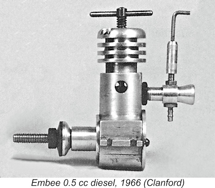
 spacer rings of different heights appears to have been abandoned – presumably experimentation had enabled the manufacturer to settle upon an optimal cylinder height. It is this version of the Embee which is most familiar to model engine aficionados.
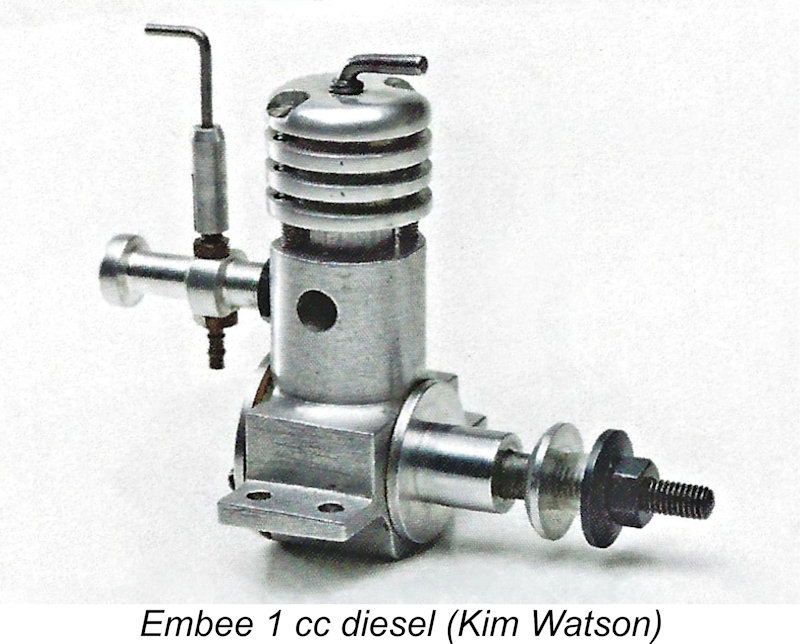 encountered an example myself. Ted also reported the existence of a 1 cc prototype, of which an illustration was included in his book. Again, this design never appears to have made it past the prototype stage, although Fisher did illustrate an example of this model installed in a scaled-down rendition of the 1938 Cloud Airmaster free flight model.
 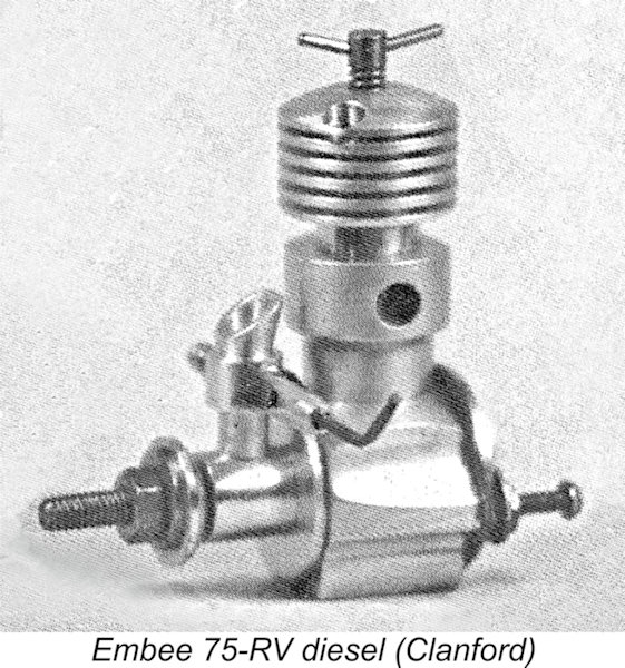 included details of a new Embee model - the Embee 75-RV unit. This engine was a crankshaft front rotary valve derivative of the original Embee sideport model. Chinn stated specifically that it was being manufactured by Peter A. Moore from a location at 72 Fairfax Road in Leicester.
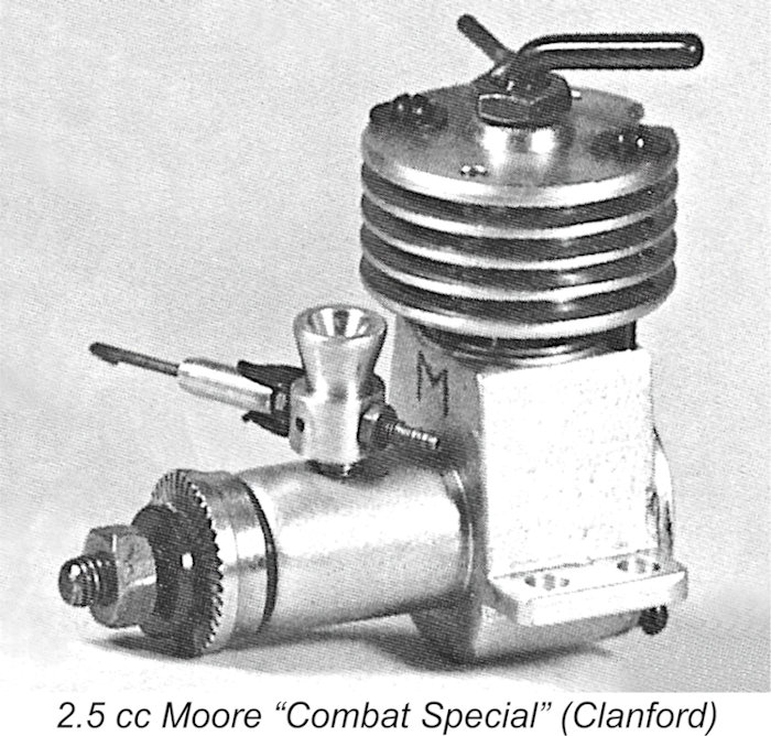 In the same article, Peter Chinn mentioned several additional Embee models. One of these was a 2.5 cc ball-race diesel. Reference to the books by Clanford and Sladden confirm the existence of this unit, which was actually designated as the Moore “Combat Special” 2.5 cc diesel as opposed to an Embee model. It seems to have been produced in several variants, all of which were radially-ported twin ball-race barstock diesels. Given the fact that it would have been competing with such diesels as the tuned Oliver Tiger and the MVVS D7 then in common use for combat, it must have been quite a performer! It was never advertised, hence evidently being made in very small numbers. Examples are extremely rare today - I've never encountered one.
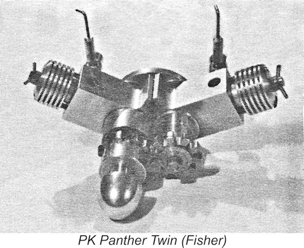 shallow-angle V-twin, 45 degree V-twin and even side-by-side in-line twin. The implication is that the twins were individually constructed to special order, never really attaining the status of serial productions. Probably the closest that they came to achieving this status was the PK Panther V-twin which was produced by Peter Moore in very small numbers to the order of Performance Kits owner Peter Fisher. It featured twin ball bearings supporting the main prop drive crankshaft.
 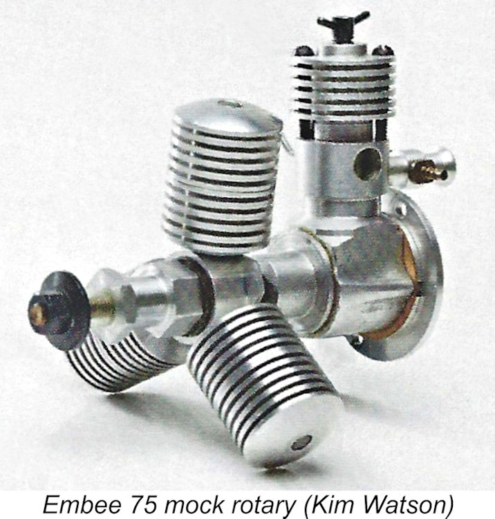 sideport capability of running in either direction. According to Clanford they were fun to play with but impractical to use in a model aircraft due to their very low power-to-weight ratios. They were perhaps better suited to model boat work.
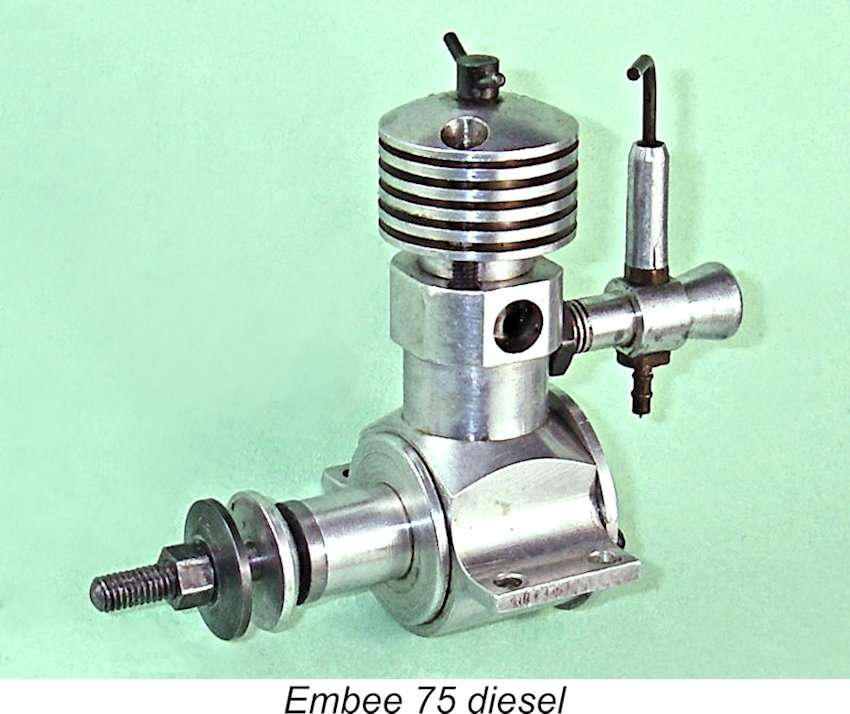 The Embee 75 diesel presents itself very much as a “model engineer’s” creation. The familiar production models are of barstock construction throughout – no castings are used anywhere. Indeed, the Embee's eminent suitability for home construction led to the after-the-fact creation of plans for the engine by
 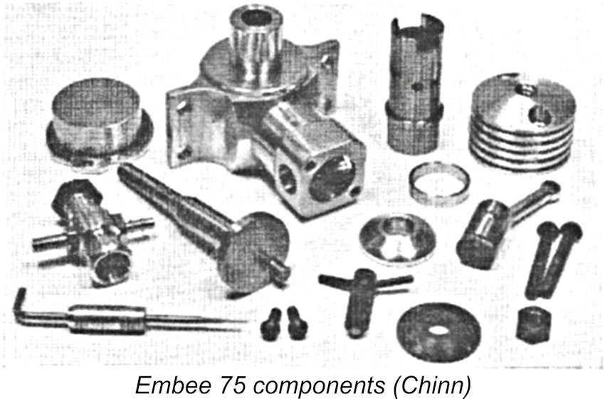 Although its appearance was very different, the functional design of the Embee followed that of the earlier Mills .75 very closely. The main difference was the method of securing the cylinder. The Embee did not use a screw-on cooling jacket. Instead, the cylinder was located vertically by a flange placed well above the exhaust port and resting upon a spacer ring which in turn bore against the top of the crankcase. It was this spacer ring which had been supplied in varying lengths with the prototype models to permit variation of the cylinder height relative to the engine’s axis. Presumably further testing had allowed the manufacturer to settle on the ideal spacer dimension for best all-round performance.
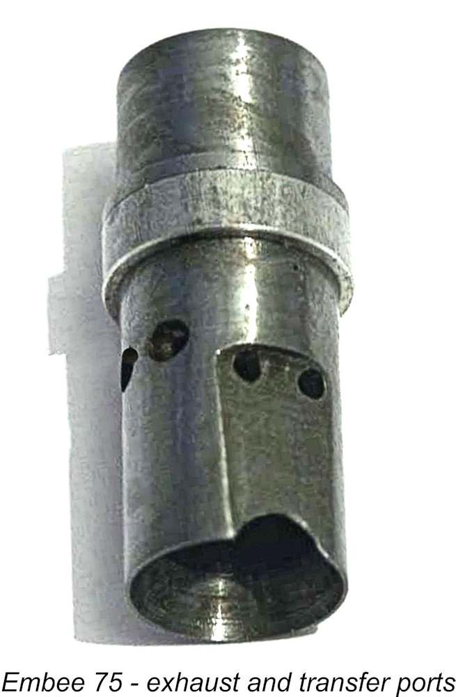 A slip-on cooling jacket bore against the top of the cylinder location flange. The whole set-up was secured by two long bolts which passed through holes in the jacket to engage with tapped holes in the upper deck of the crankcase. This design relieved the main working length of the bore from any installation stresses – a good feature.
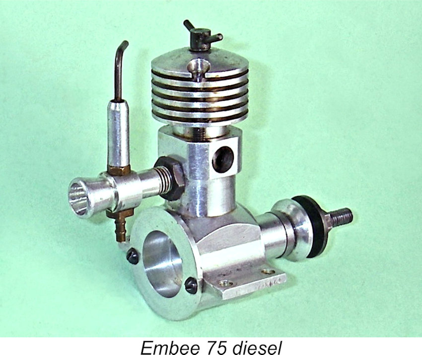 sufficient to allow the shaft to set back to the point at which the crankpin comes into contact with the backplate. This is clearly an unacceptable condition for operation, particularly if the engine is operated in pusher mode or if (as often happens with sideport engines) it starts backwards.
 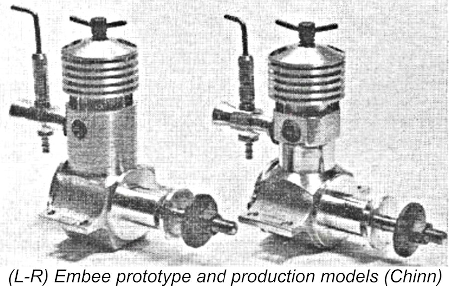 The Embee 75 was the subject of a
 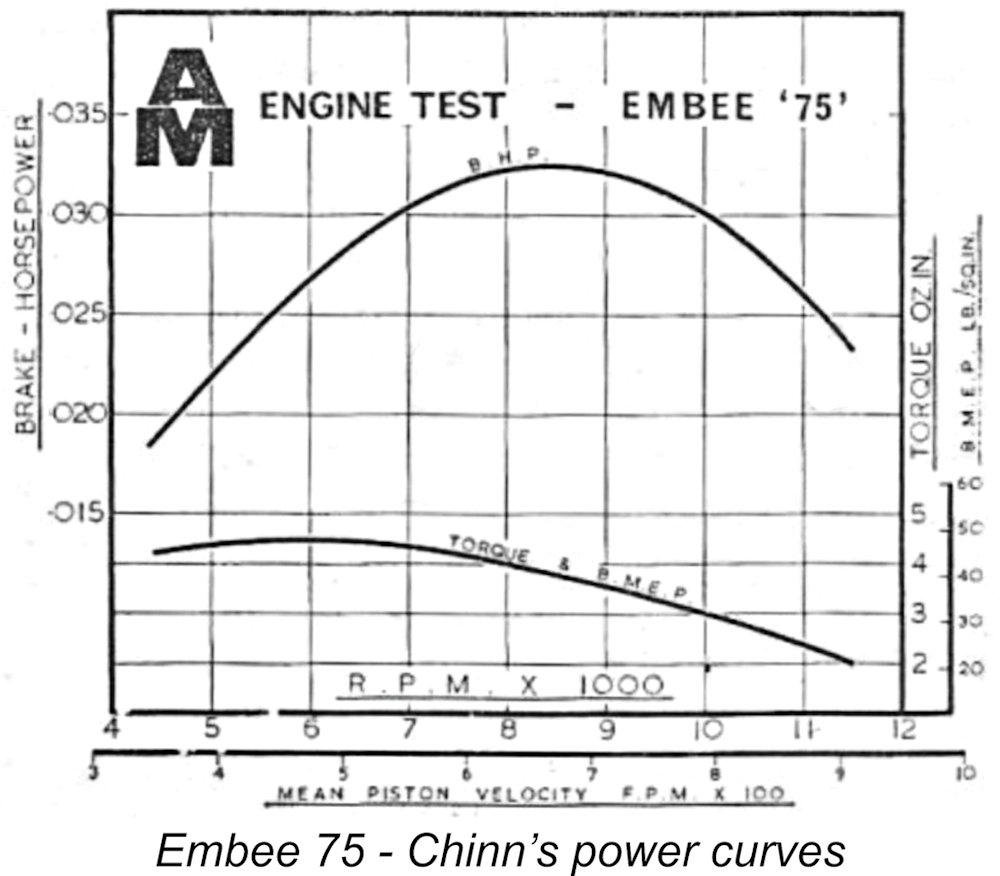 Running qualities were reported to be good. The Embee ran “quite smoothly” and steadily, with relatively low levels of vibration. Chinn’s main criticism was the small size of the compression control, which made the engine “rather uncomfortable to operate”. The fact that the contra-piston was quite tightly fitted and became more so as the engine warmed up acerbated this issue. Fortunately, Chinn found that after the settings had been established, the Embee required little fiddling with the comp screw. The needle valve setting was also found to be relatively non-critical.
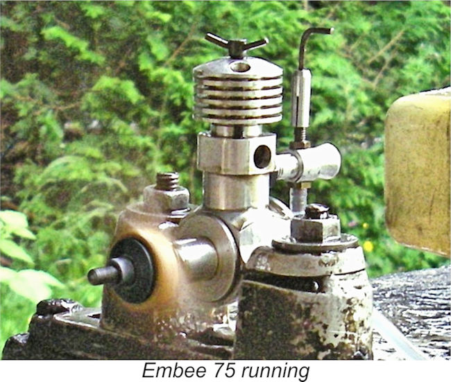
 I also agree completely with Chinn’s assessment that the comp screw could have been made a little more substantial for user comfort, especially since my example proved to have a very tightly-fitted contra-piston, just as Chinn’s test example had done. When the engine was fully warmed up, the contra piston tended to stick in the bore, refusing to follow the comp screw when it was backed off. Fortunately, the engine will start and run at the same setting once the best running position has been established for a given prop and fuel.
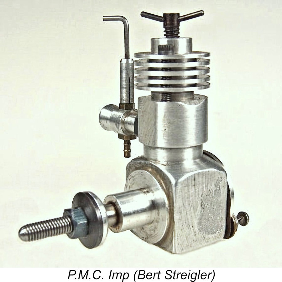 Not having access to an actual example of this engine, I’ll have to rely very heavily upon the description published by the late Ron Chernich in his previously-cited article on the Imp. The most significant visible change was the transposition of the inlet and exhaust ports. The inlet was now placed at the side, with the single exhaust at the rear. The effect of this change was to axially shorten the engine considerably, which was probably the intention. The beam mounting lugs had been replaced by a radial bulkhead mounting ring. The cooling head shape was also a little different. Some of the cases were created from rather porous sand-castings, although most were machined from bar-stock.
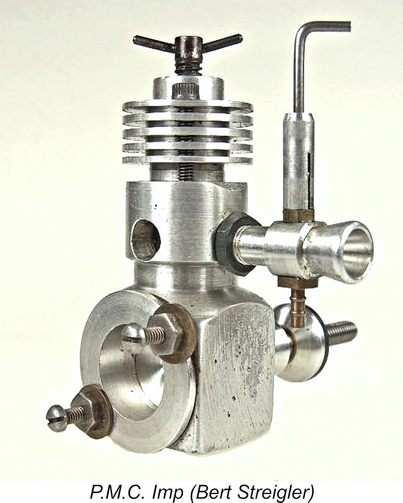 The main bearing housing was still pressed in and glued in place, but was reduced in length so that the crankshaft featured sufficient end-play to ram the crankpin against the inside face of the backplate. Indeed, the amount of end-float involved was often more than enough to permit the conrod to fall off the crankpin with the shaft at its forward position! A point to check for sure ………..
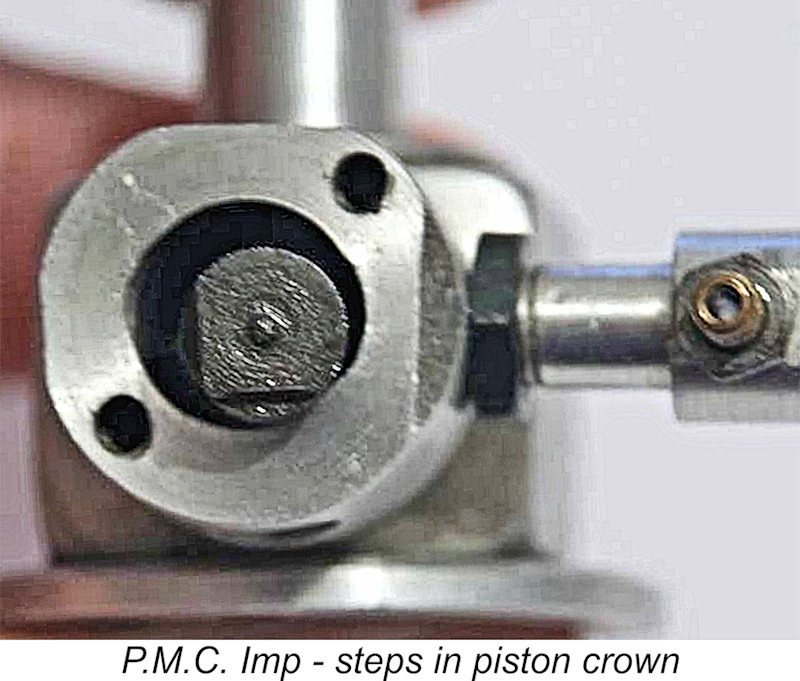 In all cases, the bypass passage continued to be formed by the creation of a flat on the transfer side of the lower cylinder. The piston crown was necessarily amended from that featured in the Embee, with two deflector cut-aways in the crown at 90 degrees to one another - a beveled one on the transfer side and a straight step facing the exhaust. The latter feature may have resulted from the use of reversed Embee 75 pistons with the extra transfer side cutaway being added.
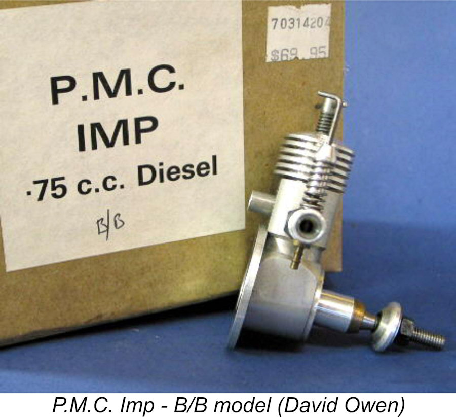
| |