
|
|
Un-Kommon Kiwi – the Pepperell "Pep 10" Diesel
In an earlier article on this website, my good mate Maris Dislers has provided I must also pay tribute to Maurice Poletti, whose outstanding 2003 self-published book entitled “Those Incredible Pepperells” covers the start-to-finish history of the engines and their manufacturers in exhaustive detail, including a full description of the Pep 10. It's entirely down to Maurice's efforts that the rest of us know anything at all about the Pepperell range! I freely acknowledge having made frequent reference to this invaluable source in developing this article, including the reproduction of a number of illustrations which it includes. Maurice’s super-informative book is long out of print, but used copies may become available from time to time. For the convenience of my readers, I will now summarize the background to the introduction of our central subject - the Pepperell "Pep 10" diesel of 1950. Those already familiar with this story are invited to skip to the following section of this article. Background
Vern Pepperell had a solid engineering background stemming from his early education in the marine engineering field (although he never actually went to sea) followed by his involvement with the motor trade and precision manufacturing fields. Vern’s association with model engines began in 1936, when his 15 year-old aeromodelling son Ira pestered his dad into making him an engine.
Following the conclusion of the war, Vern Pepperell’s thoughts immediately turned to a resumption of his earlier experiments with model engines. There had been no thought of putting the pre-war sparkies into series production, but the importation of model engines to New Zealand immediately following WW2 was rendered both difficult and The Pepperells were residents of Onehunga, a suburb of Auckland lying some 8 kilometers south of the Auckland city centre on New Zealand's North Island. Their post-war production facilities consisted of two lathes, a pedestal drill and a bench grinder housed inside the family home, along with a simple oil-burning furnace out back for casting crankcases. A genuine “cottage industry”, in fact! Vern Pepperell was a surprisingly prolific designer and constructor of model engines, although none of his products were manufactured in significant quantities by international standards. Maris Dislers has provided an excellent summary of the various Pepperell models produced over the years – interested readers are referred to that article for details. Vern followed this up by making an experimental 2.1 cc diesel in early 1946. This design was strongly influenced by Vern’s examination of an Italian Antares diesel which had been brought back to New Zealand by returning serviceman Bob McQuillan, who was a fellow member of the AMAC. Vern’s design used the piston-valve transfer principle employed in the earlier Pepperell “Godwit” sparkies, almost certainly making it unique among model diesels. The engine apparently ran well, but fell short of meeting Vern’s performance expectations. Undeterred, Vern re-designed his diesel, coming up with his “Half inch” and “Seven-sixteenths inch” models using crankshaft front rotary valve (FRV) induction along with conventional Arden-type transfer porting. Their displacements were 0.123 cuin. (2.02 cc) and 0.094 cuin. (1.54 cc) respectively. They were constructed to a generally similar design, displaying a few highly original features. Most unusually, they were identified by their bore dimensions! Perhaps the engines' most striking feature was their utilization of fixed fuel jets, with the mixture being varied through control of the incoming air supply. This approach to fuel mixture adjustment had seldom been seen previously - the most notable earlier examples had been the original Atom and Perky spark ignition units from America as well as the 1945 French Airplan offerings and the 1944/47 Atomatic diesels from Rome, Italy. It's possible that the Antares was not the only early Italian diesel to be brought back to New Zealand by Bob McQuillan................
The smaller 1.54 cc “Seven-sixteenths inch” variant outsold its larger 2.02 cc sibling by a considerable margin, remaining in production until 1952, when all Pepperell model engine manufacture ceased after the Pepperells decided to divert their efforts into more remunerative activities. A test of a Pepperell “Half-inch” unit forms part of Maris Dislers’ previously-cited article. A very informative article covering the smaller “Seven-sixteenths inch” variant may be found on the late Ron Chernich’s frozen but still fascinating “Model Engine News” (MEN) website. Well-received as these engines were, they were by no means the last diesels developed by Pepperell. A number of experimental diesels based on the original theme were constructed in displacements ranging from 0.037 cuin. all the way up to 0.455 cuin. One of these, the scaled-down 0.037 The final all-new Pepperell design to be produced in commercial quantities appears to have been the central subject of this article – the 1950 Pep 10 diesel of 0.106 cuin. (1.74 cc) displacement. This was constructed to a completely new design rather than being a development of the earlier models. Although very few examples of this engine ended up being made in total, the Pep 10 pointed towards the direction in which the Pepperell designs might have developed if production had continued past 1952. As-new examples of the Pepperell engines are almost never encountered outside New Zealand – even in that country, they’re far from common. This being the case, it was purely a matter of good luck (and a dip into my wallet!) that enabled me to acquire a near-pristine example of the Pep 10 diesel. My good fortune in making this acquisition placed me under an obligation to share it to the extent possible. Here goes …………… The Pep 10 Diesel – Description
Moreover, the Pepperell 10 was the subject of a review by Stan Pilgrim which appeared in September 2001 in issue no. 48 of the Australian newsletter “Australian Control Line News” (ACLN). This was particularly helpful in clarifying the engine’s cylinder porting arrangements. The Pep 10 diesel is a surprisingly up-to-date design by 1950 standards. One’s first impression is that it’s a sturdy and very well-made unit of generally clean and “uncluttered” arrangement. In terms of its design layout, it would not have looked out of place if it had been released 5 years later!
A noteworthy feature of this engine is its bore/stroke ratio. This figure works out at 1.29 to 1 – an unusually oversquare ratio for what was presumably intended to be a simple sports diesel. Interestingly enough, the far later Katipo 1.48 cc diesels from nearby Panmure used the same bore/stroke ratio – an influence, perhaps?!? The engine is built up around a substantial gravity die-cast crankcase which was very cleanly produced from a permanent mold. This casting incorporates the main bearing housing and intake venturi in unit. The case is provided with seemingly sturdy lugs for both beam and radial mounting. The fact that the Pepperells went to the trouble of making a permanent mold for this design implies that they had every intention of putting it into series production at some level. The fact that the case has a very attractive matte finish also speaks to such an intention.
The transfer ports consist of ten small holes drilled below the exhaust ports, somewhat reminiscent of the approach adopted by Yulon. These ports draw mixture from an unthreaded annular passage located immediately below the cylinder installation flange and running all the way around the cylinder at transfer port level. In turn, this annular passage is supplied with mixture by six externally-formed bypass channels which interrupt the male cylinder installation thread. The use of this system ensures that performance should be unaffected by the annular orientation of the screw-in cylinder when fully tightened down. Obviously, the provision of any overlap between transfer and exhaust ports is not possible with this design arrangement. In order to provide an adequate transfer period in such a design, the exhaust has to open extremely early. In the case of the Pepperell, the exhaust opens at only 100 degrees ATDC, giving a seemingly excessive exhaust period of 160 degrees - not unprecedented, but pretty radical for a simple sports diesel. Even with this exhaust figure, the fact that the transfers don't begin to open until 136 degrees ATDC restricts the transfer period to a mere 88 degrees. The only other 1.5 cc diesel of my acquaintance having a comparably radical set of timing figures is the E.D. Hornet. I would anticipate that the very early exhaust opening would result in the Pepperell having a sharply penetrating exhaust note, again just like the Hornet.
The shaft features a taper at the front end to secure the light alloy prop driver. This component has an appreciable length, which has the effect of placing the prop disc well in front of both the cylinder and the needle valve. The front of the shaft is axially drilled and tapped 3/16 UNF to accommodate either a threaded rod with nut and washer (as on my example) or a simple spinner bolt – both arrangements have been encountered. The hope was clearly that these components would bend in a crash rather than exposing the shaft itself to damage. The Pep 10 departs from the design of the earlier Pepperell diesels in utilizing a conventional fuel-metering system in place of the former air control system. Several different needle valve styles are reported, but they all seem to use a split collar for tension, operating in concert with a conventional spraybar. The spraybar in my example has a working diameter of 0.112 in. (2.85 mm). It is installed in a tapped The engine is completed by a screw-in backplate. Ideally, this would be recessed so as not to interfere with the radial mounting plane. However, both my example and one of those reported by Stan Pilgrim feature backplates which protrude well into the radial mounting plane. Care would be required to avoid any risk of breaking off the radial mount lugs, particularly the poorly-supported small one at the base of the crankcase. Oddly enough, Stan's other example featured a backplate which was correctly recessed so as not to intrude into the radial mounting plane. Evidently a change was implemented at some point, possibly on the basis of sad experience .....
The Pepperell engines appear generally to have borne serial numbers. The system used by Pepperell bore some resemblance to that used by E.D. in that it defined the year and month of production together with the position of the specific engine in that month’s production batch. The first two digits defined the year of production; the next one or two digits specified the month of production; and the subsequent digits defined the position of that engine in the specified month’s production batch. Some models also featured a type designation – for example, the serial numbers of the “Seven-sixteenths inch” models appear to have The Pepperell 10 diesels evidently didn’t feature any such letter designation. The numbered example owned by Stan Pilgrim bore the serial number 5011 24, making it the 24th example produced in November 1950. Stan's other example bore no serial number at all. My own engine bears the serial number 5011 11, placing it in the same batch as Stan's numbered example. The implication is that at least 25 examples were made in November 1950. As stated earlier, Stan's other example did not display a serial number.
Overall, the Pepperell "Pep 10" gives the impression of being a sturdy and well-made model diesel of completely conventional if relatively uninspiring design by the standards of its day. Despite its restrained specification, it gives the impression that it was well able to give very good service to its owners, albeit at somewhat modest levels of performance. The one possible fly in the ointment might be the relatively small pillars of material left between the exhaust ports to retain the upper cylinder. A hard impact might have an adverse effect upon cylinder bore alignment. OK, so much for expectations! How did the Pepperell 10 actually perform? Let’s find out! The Pepperell 10 Diesel on Test Although it has been very well cared for, my example of the Pep 10 does appear to have done some running - there are light witness marks around the holes in the beam mounting lugs. There's also a small but detectable amount of "dry" play in the rod bearings, although nothing to give rise to any concerns. However, the fit of the shaft in its bearing is beyond reproach, while the piston fit appears to be more or less optimal - an excellent compression seal with only a modest (and desirable) "pinch " around top dead centre. Even so, I decided that I would give the engine a bit of rich undercompressed running just to be on the safe side. I elected to use an 8x6 airscrew for these shake-down runs. I didn't plan to push the engine very hard in any event - I just wanted to get a feel for its handling and running qualities as well as gaining an impression of its performance capabilities.
Set up in the test stand with its prop fitted, the Pep 10 felt really good, certainly giving the impression that it was already run in. The very small crankcase volume, early closure of the induction cycle and very late opening of the transfer ports meant that transfer pressure from the crankcase was quite high - the transfers opened with quite a crack when the engine was turned over by hand. I commenced my starting efforts by trying just a couple of choked turns and a few drops of fuel down the intake. This proved to be completely ineffective - the engine wouldn't even fire, let alone run. However, happiness was restored after I administered a small port prime - the engine fired immediately and was running in very short order. This established the pattern for the rest of the test - a light exhaust prime was pretty much essential, but starting was almost immediate after this was administered.
I then proceeded to try the engine leaned out on a series of progressively lighter loads. The Pep 10 remained very easy to set on all props tried, with running being completely smooth at all times. Both controls held their settings perfectly throughout. As expected given its exhaust timing, the engine ran with an unusually sharp and penetrating exhaust note. Some vibration was undoubtedly present, but nothing that a really firm mounting couldn't have accommodated. The very short stroke doubtless helps here. Starting continued to be completely trouble-free following a small prime. The exhaust residues remained clear throughout, showing no evidence of rapid wear on any working surfaces. The following data were recorded on test.
As can be seen, the Pep 10 did itself proud, performing at a more than acceptable level for a 1.78 cc diesel of 1950 vintage. It appeared to develop a peak output of around 0.147 BHP @ 12,000 RPM. figures which are quite comparable with those reported for some of the more highly-regarded contemporary 1.5 cc - 1.8 cc diesels from the likes of Allbon, Elfin and FROG. It would have proved to be a fully satisfactory powerplant for the sport models of its day. The Pep 10 came through its test with flying colours, showing no evidence of any mechanical difficulties. It seemed to be a sturdy powerplant which was well able to give hours of good service to its owners. Conclusion I hope that the combined efforts of Maris Dislers and myself, drawing upon the earlier work of Maurice Poletti, have demonstrated that the Pepperell venture resulted in the production of some very well-made engines having more than acceptable levels of performance. The New Zealand modelling community was well served by these units – many a Kiwi modeller learned his business using a model with a Pepperell engine up front! The Pep 10 was undoubtedly a workmanlike effort which had the potential to provide good service over the long haul. Its somewhat uninspiring design actually resulted in levels of performance which closely matched those of the established 1.5 cc - 1.8 cc models from the likes of Allbon, Elfin and FROG. Further development would undoubtedly have paid dividends, but the potential returns were obviously seen by the Pepperells as being insufficient to justify such an effort.
It's unclear whether or not the export of these engines was ever contemplated. If it was, it must have become clear to the Pepperell family that their “cottage industry” production facilities would be quite unable to produce the engines in sufficient numbers to serve a viable export market. A major expansion of their production facilities would have been required, along with further development work to bring their engines into line with competing products from other manufacturers. It was likely their recognition of these sad facts that caused the Pepperell family to look elsewhere for their economic future after 1952. Following a period during which he manufactured Pepperell glow plugs and Whirlwind wood propellers, Vern switched to designing and manufacturing packaging machinery, while Ira pursued a career in full-sized aviation. However, the Pepperells’ efforts had created a legacy of fine model engines which did great credit to their abilities. Like the iconic kiwi, these engines are rather elusive today, but those that do survive testify to the skill and dedication of their creators. Long may they be treasured by those fortunate enough to own examples! ___________________________ Article © Adrian C. Duncan, Coquitlam, British Columbia, Canada First published July 2024 |
||
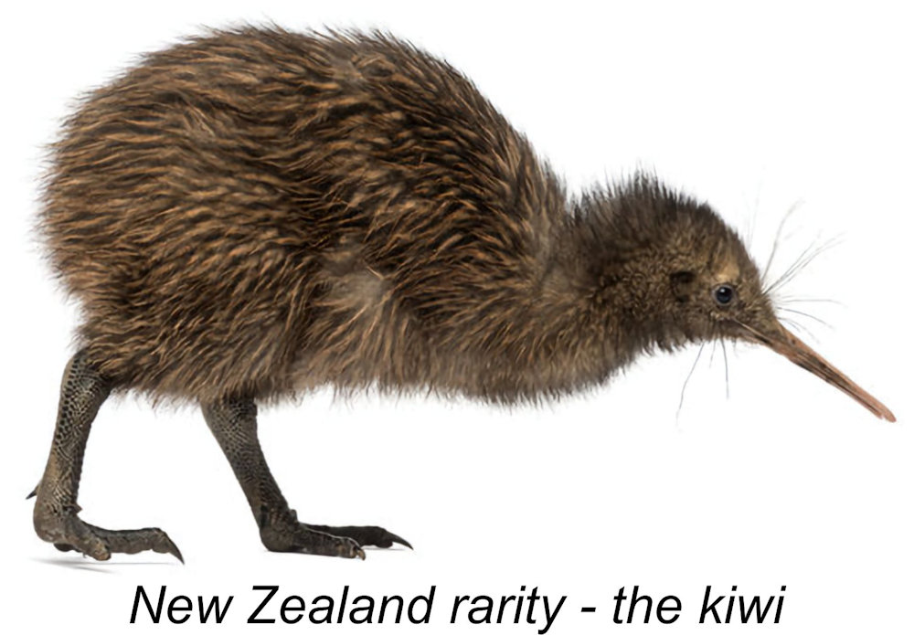 As most people know, the
 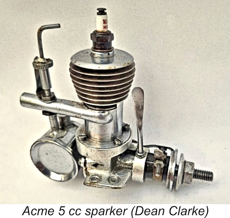 Another equally-marginalized icon of New Zealand as far as model engine enthusiasts are concerned, albeit one that did fly, is the Pepperell range of model engines. These engines rival the predominantly-nocturnal kiwi in the relative rarity of present-day sightings. They were produced in small numbers between 1945 and 1952 as one of only four recorded commercial model engine manufacturing ventures to originate in New Zealand – the other three were the pre-war Acme 0.299 cuin. (5 cc) spark-ignition unit, the 1940 Modelair Nimrod sparkies and the mid- to late-1960’s
 The Pepperell engines were manufactured by Verner Henry Pepperell (1901 - 1966) with the encouragement and assistance of his son Verner Ira Pepperell (1921 - 1996). The two were always known respectively as Vern and Ira, which is how I will refer to them in this article.
  This 0.61 cuin. (10 cc) sideport sparkie looked somewhat like a side-exhaust Brown Junior. Vern’s interest was stimulated by the success of this unit, leading him in 1937 to make another slightly larger 0.79 cuin. (12.95 cc) model which used crankshaft front rotary valve induction. The father-and-son team enjoyed some notable successes with these engines as members of the Auckland Model Aero Club (AMAC) until WW2 got in the way. The onset of this conflict eventually resulting in Ira joining the
  In 1940 Vern continued his association with model engines by spending three months working for Fred Macdonald at Modelair machining castings and components for the short-lived Modelair Nimrod spark ignition motors. Following this interlude, he went to work for a company called Ceramco, where his boss was Vernon B. Gray, a well-known and successful new Zealand aeromodeller. He subsequently worked at the Farmers Fertilizer works as a toolmaker.
  prohibitively expensive by government trade regulations. This created an obvious opportunity for the development of a domestically-produced range of such engines. After demobilization from the Air Force in September 1945, Ira Pepperell joined his dad in pursuing this objective, now on a commercial basis. Their first offerings were the “Godwit” piston-valve spark-ignition units of 1945.
 For the purposes of the present article, it’s sufficient to say that Vern was an early exponent of compression ignition technology, quickly developing a design for such a model and being granted New Zealand Provisional Patent No. 95137 for this design in 1945.
 These two diesels were to become Pepperell’s best-selling products, providing New Zealand modellers with domestically-produced powerplants of high quality and more than adequate performance for a wide range of sport-flying applications. As far as I know, they were never exported in any quantity, although the odd example seems to have found its way to Australia.
 Since I wasn’t prepared to subject this seemingly little-used example of the Pep 10 to the potential pitfalls of a strip-down, I had to look elsewhere for detailed technical information on the engine. Fortunately, Maurice Poletti’s previously-cited book entitled “Those Incredible Pepperells” includes a full description of the Pep 10. We're all in Maurice's debt for his preservation of this information.
  The general design of the Pep 10 follows the pattern which was becoming widely established for diesels in its displacement category as of the early 1950’s. It is a plain bearing crankshaft front rotary valve (FRV) diesel featuring circumferential radial cylinder porting. Nominal bore and stroke are 14.29 mm (0.5625 in.) and 11.11 mm (0.4375 in.) for a calculated design displacement of 1.782 cc (0.1087 cuin.). The engine weighs in at a checked
  The steel cylinder is externally threaded both above and below the cylinder installation flange. The base of the cylinder screws into a female thread formed in the upper crankcase, while the upper portion of the cylinder accommodates a screw-on turned light alloy cooling jacket. The three sawn exhaust ports are cut through the cylinder’s location flange, with a surprisingly minimal amount of metal left between them to retain the upper cylinder in place.
  The relatively heavy cast iron piston drives the crankshaft through a straight-sided aluminium alloy conrod which seems to have been machined from a piece of flat alloy plate. The main journal of the one-piece steel crankshaft has a truly heroic diameter (for a 1.78 cc engine) of 9.52 mm (0.375 in.). The shaft induction port is a simple round hole which provides a 148
  transverse hole which passes through both sides of the venturi, no nut being used to secure the component. In conjunction with the 0.212 in. (5.4 mm)
  Because of the unusually large cylinder bore and relatively thick radial mounting flanges, the crankcase is quite long, forcing the backplate to be recessed very deeply into the case to create a minimal crankcase volume. The base of the backplate recess is provided with two small holes drilled partway through in order to provide purchase for a special tool used for tightening the component. Note the evidence of tool chatter which is visible inside the backplate of my example.
 Apart from seemingly confirming that at least some 25 examples of the Pep 10 were made in November 1950, the two numbers of which I'm currently aware don't help us to get a handle on production figures. All that can be said is that the number cannot have been high. For all we know, all examples of this engine may have been manufactured in a single batch in November 1950!


 The problem facing the Pepperell family was that although their products were well received by New Zealand power modellers, there simply weren’t enough of those individuals to sustain a model engine manufacturing venture over the long haul. As of the early 1950’s, New Zealand had a population of less than 2 million, perhaps 1,000 of whom at most may have been serious model builders. Moreover, not all of these active enthusiasts were power modellers. This being the case, it seems obvious that domestic demand alone would be insufficient to ensure the long-term survival of the venture.
 | |