
|
|
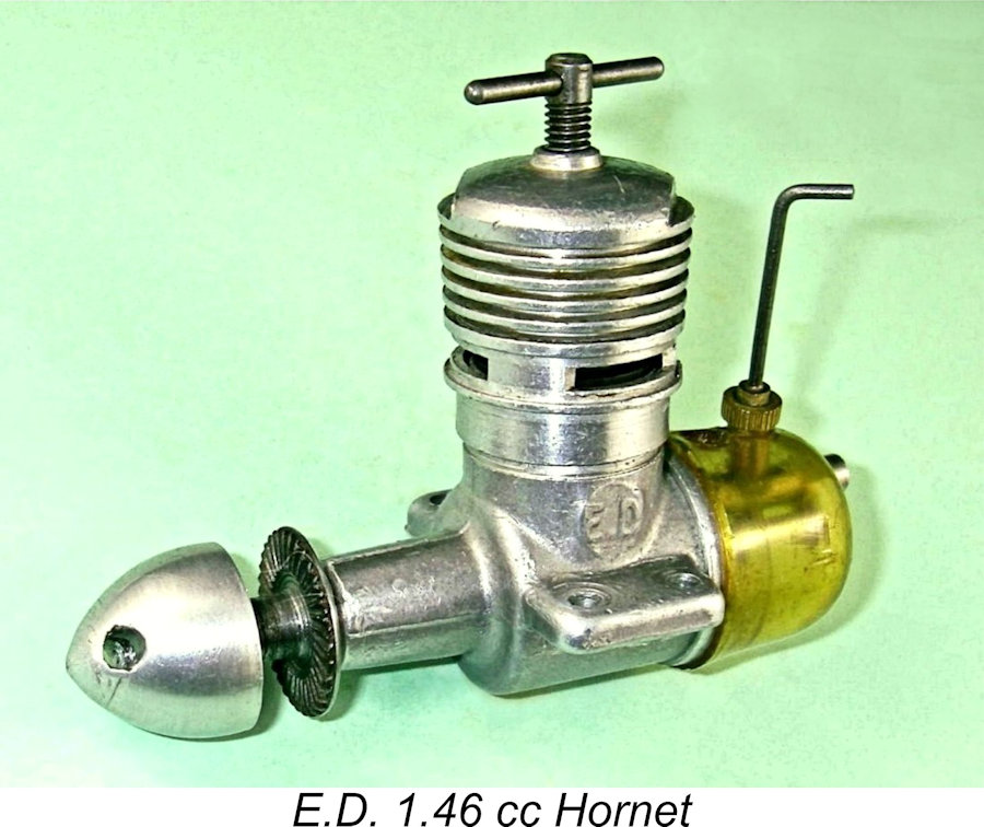
The E.D. 1.46 Hornet By Adrian Duncan with Ron Chernich
Unfortunately, my greatly-missed mate Ron left us in early 2014 without passing on the access codes to his heavily encrypted site. Consequently, no maintenance of that site has since been possible, making it inevitable that a slow but inexorable deterioration is taking place over time. It’s this issue that has led me to transfer a number of what I consider to be the more important articles over to my own site. This is one of them. Ron’s article is sufficiently comprehensive that I will reproduce his text here with only a few editorial changes. However, Ron did miss one trick – he didn’t include a later-day test report on The design of the Hornet was based in many respects upon that of the 1 cc E.D. Mk. I Bee of mid-1948. The induction arrangements and lower-end working components were identical – the differences were confined to the bore dimensions and the cylinder porting arrangements. Those wishing to learn about the early years of the E.D. enterprise are referred to my article on the history of the E.D. marque. The Hornet first appeared in late 1952, almost a year after the introduction of the iconic 2.46 cc E.D. Mk. III Racer. The Racer was the first E.D. design to be openly associated with the name of Basil Miles as its designer. Although his name was never associated directly with the Hornet, it seems all but certain that the changes to the Bee design required to produce the large model were developed by Miles. Enough from me for the present! Time now to turn the pen over to my late and very much-missed mate Ron Chernich for his take on this very individualistic engine. The E.D. Hornet as seen by Ron Chernich
The placement of a pre-announcement in that issue is understandable, since up until the mid-1960's the Christmas issue of “Aeromodeller” was termed a "bumper" issue, being almost twice normal size. Moreover, it appeared a month in advance of Christmas, thus offering enhanced sales prospects to advertisers. These special annual issues were eagerly awaited by British and Commonwealth modellers, so the full-page ad (reproduced below at the right) coupled with the low price of £3 including tax doubtless created a strong early demand for At this time the engine had not yet been christened, simply being called the "E.D. 1.46". The engine filled a gap in the E.D. range catering to competition classes that called for engines under 1.5 cc (hence the slight margin on displacement). The range had hitherto comprised the 0.46 cc "Baby", the 1 cc "Bee", the 2 cc "Competition Special", the 2.46 cc "Racer", the 3.46 cc "Hunter", and the 5 cc "Miles Special" (seems like someone at E.D. really liked "point four-six" for some reason!). However, the follow-up campaign was sporadic. No further full-page ads appeared, while E.D. often chose either to focus on other engines in their range or to feature their R/C gear, with engines not being mentioned at all (for a fully-detailed history of E.D., see the E.D. Story). Ron Warring reviewed the engine for the February 1953 issue of “Aeromodeller”, while the rival publication “Model Aircraft” carried an anonymous review in their August issue (it’s almost certain that these anonymous reviews were conducted by Peter Chinn). Whoever he was, the “Model Aircraft” reviewer stated that the engine had then "recently been christened" the "Hornet", a fact borne out by the E.D. ad which appeared in the following month’s issue of “Aeromodeller”. Description
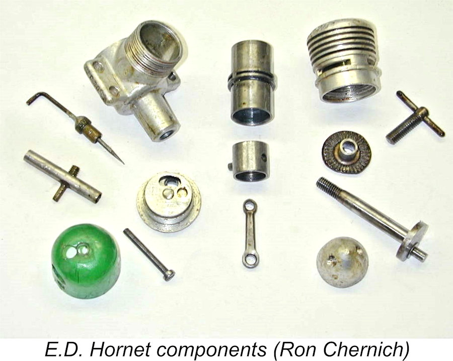
The 7/32 in. diameter crankshaft ran un-bushed in the cast aluminium crankcase. Both liner and piston were hardened steel rather than the more normal steel/cast-iron combination. Dick Roberts’ review in the “Engines Old & New” feature of the April 1998 issue of “Aero Modeller” stated that the very heavy piston was cast-iron, but it was most certainly not in the three examples that I examined. (Editor’s note – both the “Aeromodeller” and The liner dropped into a bore formed in the upper crankcase that was 0.020 in. larger than the lower liner’s outside diameter. It was centered and retained by the cylinder’s cooling jacket, which screwed onto the externally-threaded uppermost projection of the crankcase. This resulted in a 0.010 in. wide peripheral cavity that formed the bypass passage supplying the three transfer ports located immediately below the cylinder location flange. This scheme certainly eased manufacturing tolerances and reduced the number of operations. The arrangement first appeared on the E.D. 0.46 cc "Baby" that had been introduced in April 1952.
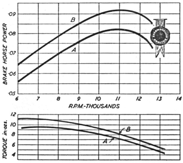
The result is an unusually large bore/stroke ratio of 1.327 to1. Most other 1.5 cc diesels of the period were nearer to "square". The result is a comparatively low piston velocity, which would be good for both wear and vibration. However, things get really interesting when we begin to consider the timing. Like other contemporary manufacturers, E.D. used a thin slitting saw to produce the peripheral porting by making three 0.047 in. wide cuts at 120° radial spacing. These This drawing, made from measurements taken from a Hornet in my collection, shows that E.D. chose the latter route. The transfer period is a respectable 110° - fair enough, but this results in a gigantic 169° period for the exhaust. This early exhaust opening means that the cylinder vents pressure well before it has finished doing the work that it could have done. It also means that the exhaust exits at a high pressure and hence velocity. The anticipated result would be an engine that is not as powerful as it could be, but with an exhaust note that certainly makes it sound like a high-powered screamer! However, the “Aeromodeller” test figures don't support this conclusion, presenting performance data which was well up to the best then-current expectations for a 1.5 cc diesel. Although less flattering, the “Model Aircraft” BHP test figures still showed an engine having a comparable performance to that of contemporary peripherally-ported diesels such as the FROG 150 and Allbon Javelin. The following table summarizes the comparative performance picture.
(† Data extracted from reviews appearing in “Aeromodeller”, 1951—64) Sadly, the above data are somewhat suspect. The test equipment and procedures used may well have been different between the tests, while the test conditions (pressure, temperature, and humidity) are not noted. Add to this the fact that most were based on testing a single example of the type. We can but hope that the figures are sufficiently indicative to allow us to say that E.D.'s choice of an unusually early exhaust opening for the Hornet did not result in a complete dog. Even if we accept Peter Chinn’s lower figures (0.119 BHP @ 11,100 RPM), the Hornet was still in the middle of the pack. The disc rear rotary valve (RRV) would be conventional except that, like the Series 1 E.D. Bee, the backplate screws into the crankcase. This means that the location of the inlet cannot be determined and machined until a specific backplate is screwed into a given crankcase. Once that’s done, the backplate can be drilled for the venturi tube, but will only be in the correct orientation for that particular backplate/crankcase pair, which therefore have to remain together thereafter. The rotor is made from aluminium alloy - not the best material for this hard-worked component, especially when running against an alloy backplate surface. Marks on the edge indicate that it was stamped from 1/8 in. sheet. It is timed to open at about 45° after BDC and remain open for about 170° - quite reasonable figures. It is permanently pinned to the backplate.
The conrod is hardened steel, making all the working bearings except the main journal hard steel on hard steel – not an ideal configuration. The steel prop driver locks on a shallow taper on the shaft. The shaft thread is 2BA and the turned aluminium spinner nut is extensively hollowed out. Reassembly is a bit of a chore. Place the conrod, sans the piston, on the crankpin with the shaft installed sans the prop-driver and set at TDC. Then place the rotor so that the blind hole for the crankpin is in line with the venturi. Screw the backplate into the case until it is close to the crankpin with the venturi oriented at the "12 o'clock" position. Now push the shaft back and jiggle it to engage the rotor, squinting down the case opening as required to ensure it has been inserted into the blind hole and not the rotor inlet opening! The backplate can now be screwed up, pushing the shaft forward, and normal assembly can proceed. In a word, painful! There is another downside to the cylinder design. Cylinder/piston pairs wear into each other with a very specific piston/liner orientation. Reassembling the engine with the liner rotated even a few degrees is highly likely to cause accelerated wear. But due to the close fit of the liner in the cooling jacket, it is impossible to keep the liner still as the head is tightened, so assembling in the same position is impossible. (Editor’s note – warming the jacket before installation can do much to alleviate this issue – A.D.). The lesson is - don't disassemble the engine any more than absolutely necessary. And if you must disassemble it for some compelling reason, be sure to mark the radial position of the cylinder prior to dismantling. Running (Editor’s note – check the shaft end-float before running any Hornet, since if this is excessive the crankpin can bear against the rotary disc, to its great detriment. The maximum rearward movement of the shaft has to be resisted by the front of the main bearing rather than the disc. See my detailed comments on this issue below in the testing section of this article – A.D.)
The engine is quite easy to start, which is good because the tank is a leak that does not have to wait to happen! The best that I can say is that the ease of starting means that you don't lose the lot before you get it running and can top the tank up - upon which, fuel will start blowing out the filler hole as well as at the point where the venturi passes through the rear wall! But for all that, the Hornet is a delight to handle; flexible in speed range and insensitive to the needle setting. It does vibrate a bit (the crank not having any attempt at counter-balancing to offset the very heavy piston). E.D. must have noted this, as later models came with a stamped compression locking lever - a most necessary addition in my experience. E.D. tanks deteriorate and crack with age. The tension under which the alloy retention screw places the tank does not help either. Even if the tank leaks so badly as to be unusable, it's not a good idea to remove it as it provides support for the venturi, which is a light press fit in the backplate casting. Without the tank, the venturi can also rotate, making it even more likely to vibrate loose. (Editor's note - if planning to run the engine without the tank, a little low-strength (Purple) Loctite can be used to stabilize the venturi - A.D.). Serial Numbers E.D. invariably stamped serial numbers on their engines. These numbers were more like a coding scheme than a sequence, hence appearing rather "opaque" to the uninitiated. The system used by E.D. is fully explained in the separate article covering the E.D. story. It is unusually informative, each sequence being unique to the type of engine, the year and month of production and the position of the engine within that month’s production sequence for the particular model. Suffice it to say here that the Hornet was identified by the model letter “Z”. Taking Hornet no. ZM 55/52 as an example, this sequence indicates a Hornet (Z) produced in November (M) 1952 as engine number 55 of that month’s batch. How much more definitive can you get?!? It was E.D. expert Kevin Richards who “cracked the code” of the E.D. numbering system. At my time of writing (2007), Kevin had 12 Hornets in his collection varying from "New-In-Box" to "Junker Awaiting Rebuild". He confirmed that they all had rather low values for the monthly batch numbers, indicating relatively low production figures for Hornets compared to Racers, Bees, Mk II's and Comp Specials. Conclusions The 1.46 cc E.D. Hornet was a powerful, noisy engine which was easy to handle and well suited to sport and FF scale flying. It was a direct drop-in replacement for the 1 cc E.D. Bee and I'm sure that many an overweight and underpowered scale free-flight model took advantage of this. The engine was a slow but steady seller, remaining on offer even after the 1957 introduction of the reed valve 1.46 cc Fury. Its manufacture continued for almost ten years until the April 1962 fire put paid to almost all engine production by the original E.D. company. From a construction perspective, the engine is very simple. Apart from the tedious business of the screw-in backplate-positioned rotary valve, it would have been easy and inexpensive to produce in series. Certainly, a modern engine builder looking for a fun project could do worse than replicate the liner/transfer system. Dick Roberts’ previously-cited article suggests that Hornets were not made in as great numbers as other contemporary E.D. engines, a conclusion which is well supported by Kevin Richards’ comments on serial numbers. The Hornet is hence a comparatively rare engine these days. If you do have the chance to acquire one, be sure to give it a run! I'm sure that the noise will surprise and delight you - the neighbours may perhaps be somewhat less delighted........... Enough from me - now back to Adrian ………………….. The E.D. Hornet on Latter-day Test
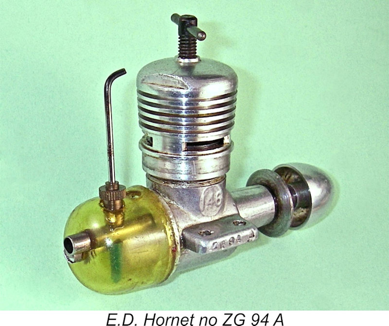
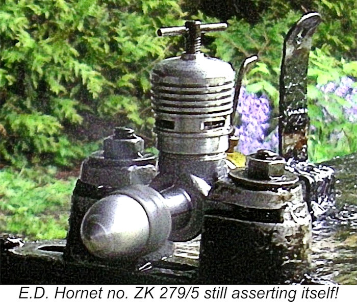
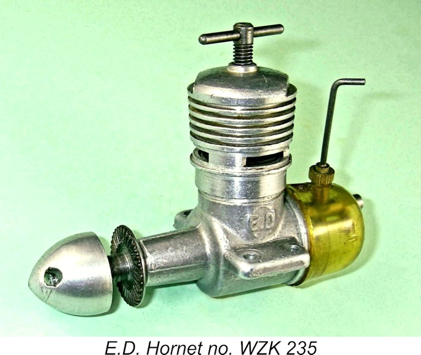
I had four examples of the Hornet from which to choose. These bore the serial numbers ZA 195/4, WZK 235, ZK 279/5, and ZG 94 A. The W which appears in the second of these sequences confirms that it was originally a water-cooled marine example from October 1955 which has been retro-converted to aircraft specification. ZK 279/5, also from October 1955, is an original aero model which has clearly seen some previous use and is well freed up, although it remains in excellent original condition. I elected to use that example as my test engine.
In his “Model Aircraft” test of August 1953, Peter Chinn (assuming that it was he) reported a far Most interestingly, Chinn reported that the first example that he had tried proved to be very much an under-performer, only managing a peak output of around 0.093 BHP @ 10,600 RPM. This was a sufficiently discouraging performance to prompt Chinn to obtain a second example, which performed far better. This highlights the widely-reported impression that E.D. engines were noted for variations in performance between different examples of the same model. It also bears out the wisdom of testing multiple examples where possible. A final test report on the Hornet appeared in the January 1955 issue of "Aeromodeller" as one of three revised "Engine Analysis" mini-reports on then-current 1.5 cc diesels. These revised reports were undertaken following the magazine's adoption of the Eddy Current Dynanometer in June 1954. Results using the new equipment tended to be significantly lower than those obtained with the former torque reaction rig.
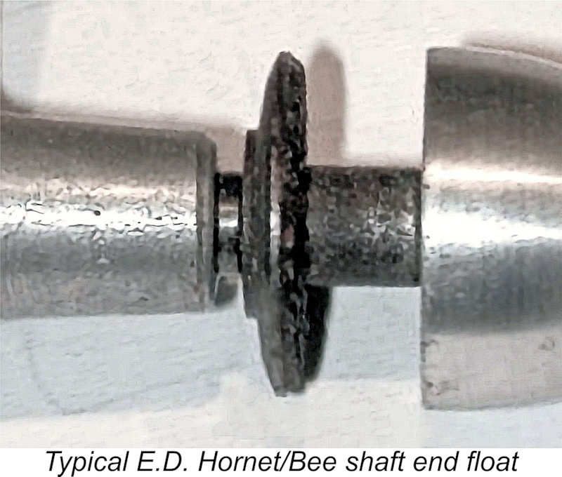
Returning now to my own testing, one point that is well worth receiving some attention when planning to run any example of the Hornet (and the Bee for that matter) is the previously-mentioned issue of shaft end-float. The steel prop drivers used on both models were secured on a shallow self-locking taper at the front of the shaft. For reasons which defy comprehension, the female taper in the driver was invariably cut too shallow, leaving a considerable gap between the rear of the prop driver and the front of the main bearing. The image attached below at the left shows the kind of gap typically encountered with an unmodified example of a Hornet or Bee.
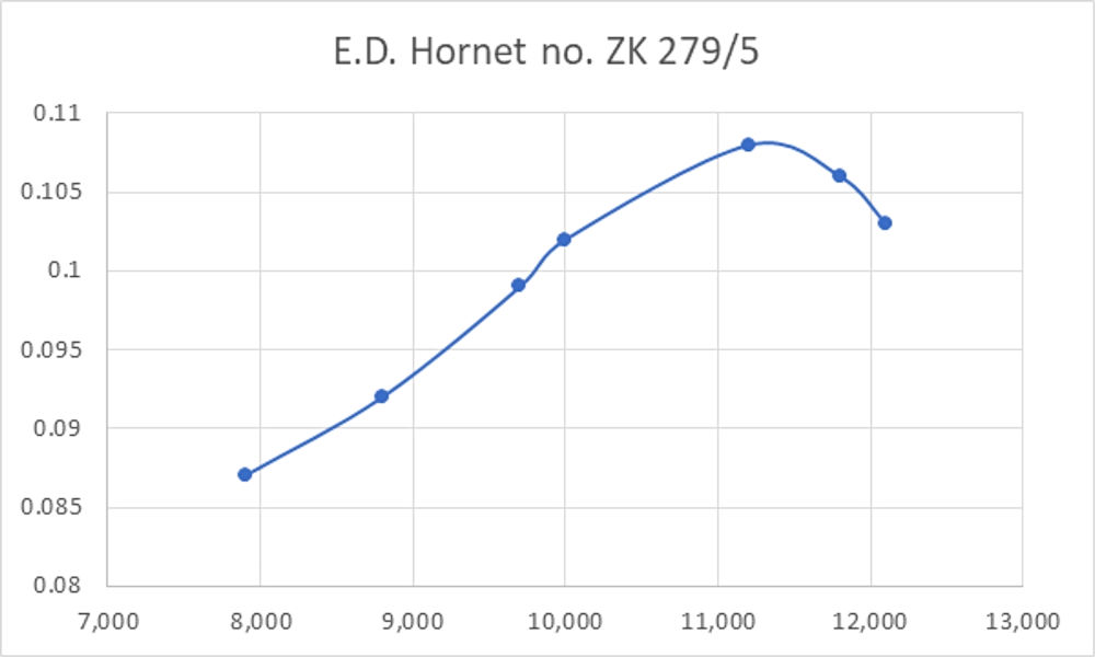
The fix is either to install a steel spacer of suitable thickness between the prop driver and the main bearing or to cut the female taper in the prop driver a little deeper as required. I’ve always adopted the second of these alternatives, since it confers the added benefit of increasing the somewhat marginal length of 2BA thread which is available to engage with the spinner nut. I have a tapered reamer having the required included angle to re-cut the taper very precisely. Like all my E.D. Hornets and Bees, the taper on my test example had already been recut to limit the shaft end-float to less than 10 thou. This meant that any rearward axial pressure or impact on the shaft would be resisted at the front of the main bearing rather than by the disc valve. Put another way, it eliminated any possibility of the rotor being pressed into service as a thrust bearing or shock absorber! Both contemporary testers had found peaking speeds in the general region of 11,000 RPM. The implication was that the Hornet is not a high-speed engine. I decided to use a suite of test props which might be expected to bracket this speed. For I began with an APC 8x6 fitted. I quickly discovered that this example was not immune from the previously-noted chronic tank leakage issue for which these engines are notorious. Upon filling the tank, a steady drip of fuel developed beneath the tank-backplate junction. However, the leak was sufficiently slow and the engine was sufficiently easy to start that it was simple enough to get it going with most of the tank still available to be consumed by the engine. I quickly found that the Hornet was a very easy starter - just as well, in view of the fuel tank leak! Like Warring and Chinn before me, I found that an exhaust prime was more or less essential for a cold start. Once that was delivered, however, the Hornet presented no starting difficulties. Hot restarts were immediate with only finger choking. As Ron had noted, the Hornet delivered an unusually sharp and penetrating exhaust note for an engine of this displacement. It proved to be very responsive to the controls, hence being extremely easy to set for best performance on a given prop. Once set, running was outstandingly smooth and consistent. Vibration was certainly noticeable, but nothing that a really secure mount couldn't handle. The following data were recorded on test.
The above data suggest a peak output of That said, the Hornet's performance was well within sight of the outputs of some of its contemporary competitors like the FROG 150, for which Chinn had reported an output of 0.120 BHP @ 12,000 RPM. At the time of the Hornet's release, the era of higher-speed British 1.5 cc diesels had yet to dawn. The cream of the consumer-grade 1.5 cc diesels at the time was a good example of the Elfin 149 (some weren't so good!), for which a peak output of 0.150 BHP @ 13,500 RPM was reported by Chinn. Even so, the Hornet wasn't totally outclassed. If operated at airborne speeds of 11,000 RPM or less, it would have done a more than adequate job of powering a typical 1.5 cc model of its era. Ron Warring's recommendation of an 8x4 prop for general-purpose use appears to be entirely appropriate. Summary and Conclusion After spending some time in the company of the E.D. Hornet, my overall impression is that it represented a somewhat half-measured effort on E.D.’s part to fill a glaring displacement gap in their range. They clearly wanted to fill that gap, but also wanted to do so at the lowest possible cost. This desire to minimize development costs was almost certainly forced upon them by the financial repercussions from the failure of the 1949 Purchase Tax case, for which E.D. do not seem to have made any adequate contingency provisions.
There’s little doubt that a 1.5 cc model designed anew from the ground up would have achieved far better results than were realized with the Hornet. I'm sure that a designer of Basil Miles' calibre must have realized this all too well - one can almost feel his frustration at being confined in effect to developing an oversized Bee rather than an all-new 1.5 cc design. However, it’s not all bad! Despite the compromises, the Hornet was a fine handling engine which ran very well within the limitations imposed by its design and would have served its owners more than adequately. It also sold at a very competitive price. It would have been particularly effective as a powerplant for free flight sport and scale models. And then there’s that exhaust note – must surely have turned a few heads, even if the performance didn’t quite match the sound! __________________________ Article © Adrian C. Duncan, Coquitlam, British Columbia, Canada First published June 2024 |
||||||
 Tucked away in the depths of the late Ron Chernich’s wonderful but sadly now-frozen “
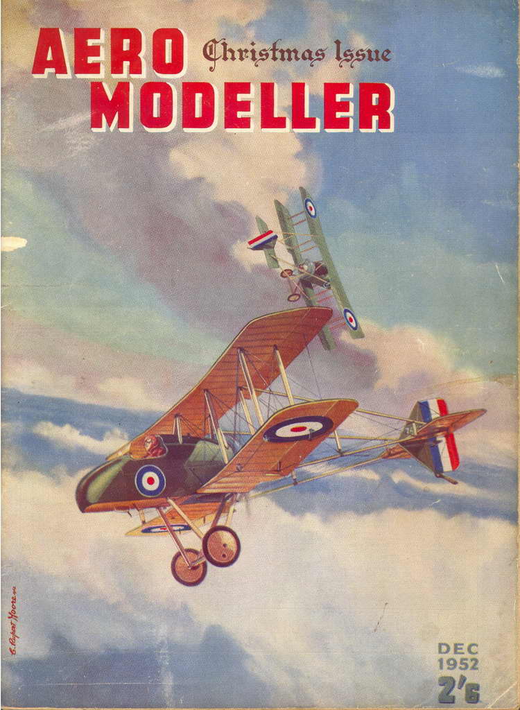 Ron here - nice to be back talking to you! The first advertisement for the "E.D. 1.46" diesel (later to be named the Hornet) was a full-page placement which appeared in the 1952 Christmas issue of “Aeromodeller” magazine. In keeping with then-current Editorial policy, this issue actually hit the news-stands in mid-November. A brief entry in the “Trade Notes” feature of that same issue claimed that supplies of the engine would appear on dealers' shelves "soon".
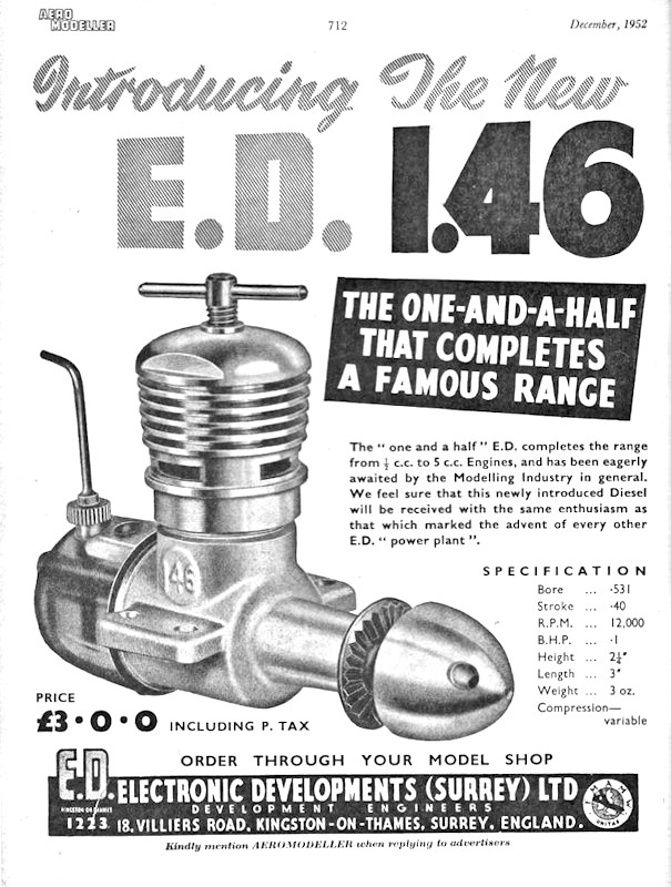
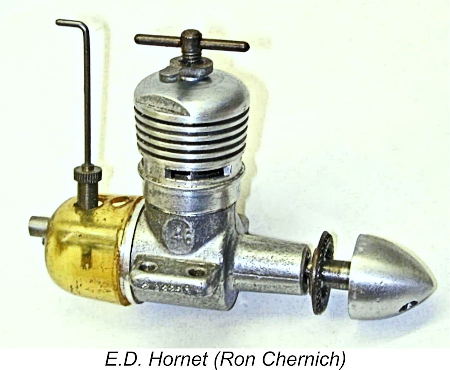 The Hornet was a peripherally-ported compression ignition engine with disc rear rotary valve induction, fitted with an integral plastic fuel tank suitable for free-flight use. It weighed in at 3.31 ounces (94 gm) complete with tank.
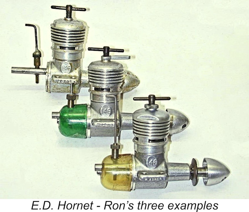
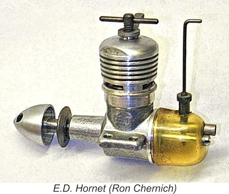 The Hornet appears quite conventional until you start measuring things. The bore is 17/32 in. (0.531 in.), while the stroke is only 0.400 in. - the same stroke as the 1 cc E.D. Bee. In fact, comparison strongly suggests that the shaft, prop driver and spinner nut were in fact E.D. Bee components, as were the backplate, rotary valve, intake, needle/spraybar, fuel tank, and the horse it rode in on! The use of all these shared components would do much to minimize costs.
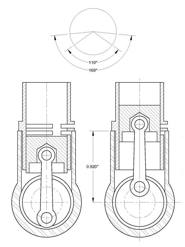
 The impressive noise made by the Hornet has already been noted, despite the fact that this is not an especially high revving engine. Like many small RRV engines, it likes a squirt in the ports for starting rather than choking. The “Aeromodeller” tester found that it gave its best performance on an 8x4 prop (wood) but would turn a 12 in. diameter wood prop without strain. This makes it a good free-flight engine, especially for scale free flight models with large round cowlings.
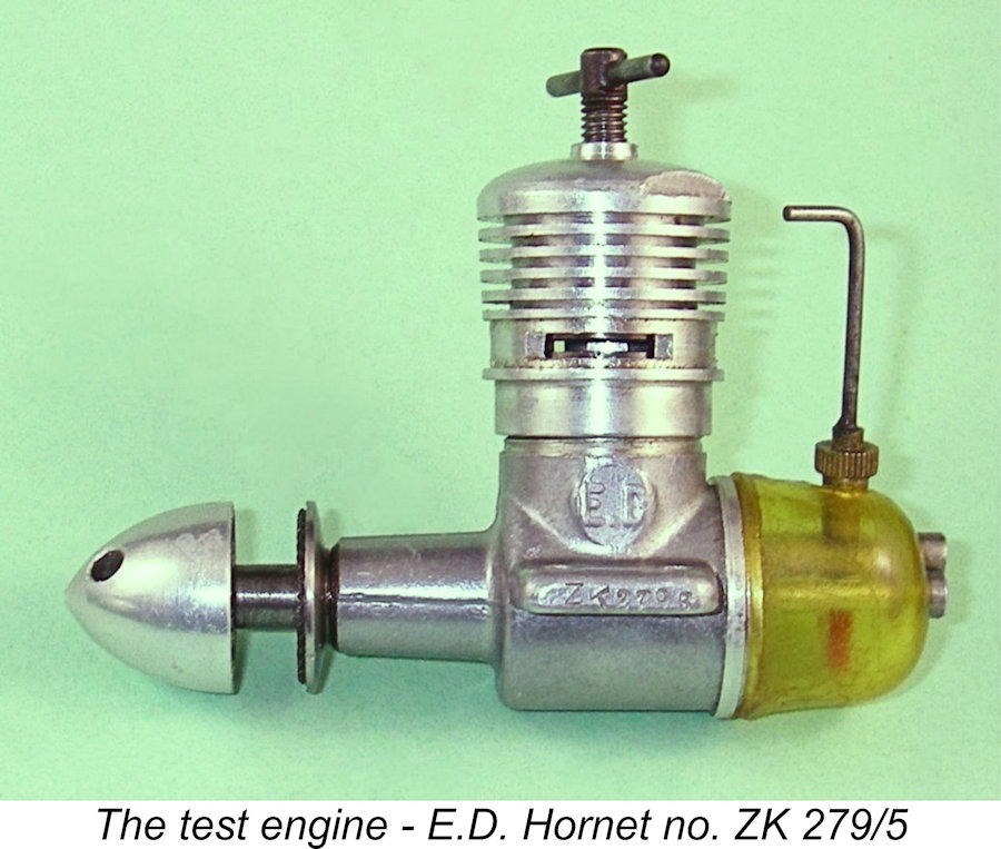 As Ron pointed out in his article reproduced above, the published test results for the E.D. Hornet appear somewhat open to question. I therefore considered it worthwhile to run a latter-day bench test on one of my own examples.
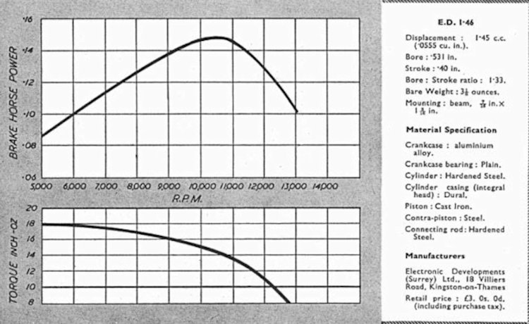 As a preliminary, I reviewed the previously-published test reports to which reference has already been made. In his
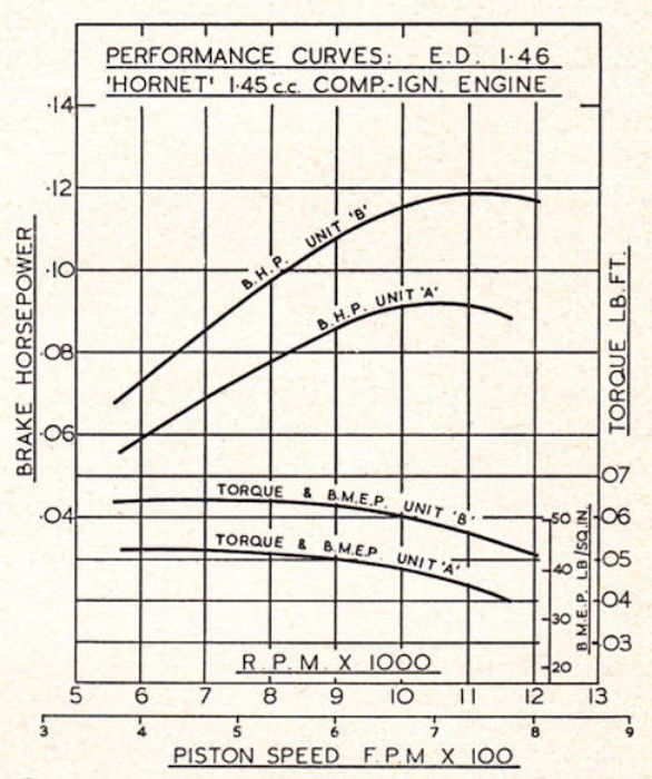
 This gap was more than sufficient to allow the shaft to move rearward to the point where the end of the crankpin was able to bear against the base of its driving socket in the disc valve rotor. This meant that any rearward pressure exerted on the shaft either during starting, through pusher operation or in a crash would be transferred directly to the disc, which then acted as a thrust bearing or an impact absorber. Not what the designer intended, and not at all good for longevity!!
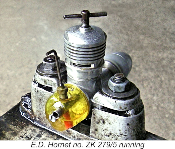
 The inevitable result was a compromise. By using as many Bee components as possible, they certainly minimized the incremental development and production costs of the Hornet, but were forced to adopt a bore/stroke ratio and a cylinder porting system which were far from ideal in design terms if high performance was the goal. The engine’s excessively short-stroke geometry and exaggeratedly-long exhaust period eliminated any possibility of the kind of torque development which would have matched that achieved by a number of more rationally-designed competing models.
| |