
|
|
The Howler .604
Regular readers of my various articles on model engine history will be well aware that I’ve always been attracted to engines which exhibit one or more unusual or innovative design features. The Howler .604 certainly fits into this category – as far as I’m aware, it’s the only model engine ever produced anywhere in the world which relied entirely upon sub-piston induction for its operational air supply. A number of other designs relied upon sub-piston induction to a very significant extent, but the Howler seems to be alone in placing its sole reliance upon that feature. The Howler has a rather unusual history by comparison with most other model aero engines. It was apparently developed for the US military during the latter stages of WW2 to power a miniature un-manned helicopter that could be deployed by US airmen downed in the ocean. The helicopter was intended to be tethered to the life-raft, its purpose being to carry a radio antenna aloft to increase the range of the radio transmitter with which the liferafts were equipped. A kite was also provided for this purpose, but of course it was useless in calm weather, hence the helicopter idea. This actually sounds like a somewhat Regardless, the prototypes apparently performed well enough to persuade the Navy to place an order. On the strength of this order, the Bone Tool & Gauge Co. spent some $50,000 tooling up to manufacture these helicopter engines in quantity at $50.00 apiece. This investment was based on the planned production of some 10,000 examples of the engine. However, the contract was abruptly terminated at the conclusion of the war before deliveries had commenced. In order to recover at least part of their investment, the manufacturers thereupon decided to see if the engine could be marketed as a model airplane powerplant – a not-illogical decision. The selling price of these post-war model aero units was set at $34.95 – a substantial figure by 1946 standards, but a significant drop from the $50.00 unit price upon which production plans were originally based. According to "Model Airplane News" (MAN) writer Edward G. Ingram, the Howler was designed by an individual named H. E. Fowler. I'd be prepared to chance a little financial flutter on the notion that the engine's name arose from its being christened the “Fowler Howler” by some wag! However, there’s no proof of this either way – it’s just an appealing fantasy! Having said this, I must record the fact that my valued friend and colleague Gordon Beeby found a number of engine-related Patents in the name of Leonard E. Fowler of Michigan, USA, one of which appears to be the basis of the Howler's unique design. The relevant Patent numbers are UK 372313 and US 1986630 (Patents were taken out in both countries). There are also some design features (e.g., the angled backplate) that display similarities to US 2218332. A number of other engine-related Patents were registered in Fowler's name, but these don't seem to be relevant to the Howler. All of this makes it appear very likely that the initial "H" applied to Fowler's name by Ingram was an error or an uncaught typo. Fowler was apparently an engineer who specialized in two-stroke engine design, having served at one time as President of a now-forgotten company called the Detroit Outboard Motor Company.
Both .15 cuin. and .65 cuin. Howler models were available, each size being built from the kits in considerable numbers. The .65 cuin. model was made available in both spark and glow-plug configurations. It must be clearly understood that the Craig Asher Howlers from the early 1960’s had absolutely nothing to do with the original Howler .604 model of 1946-47. Now, let’s have a look at the structural features of the original Howler .604 engine. Description
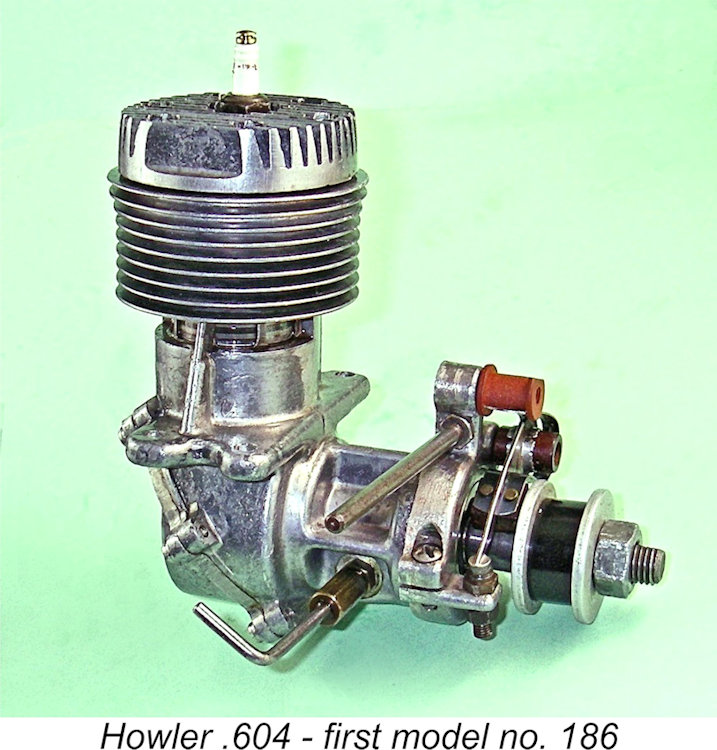
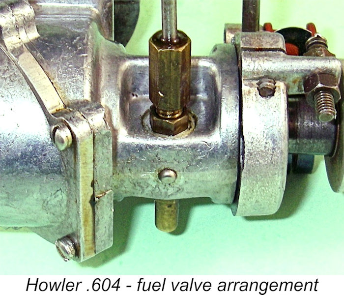
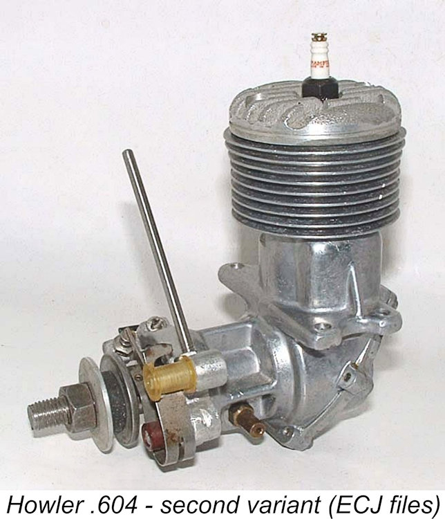
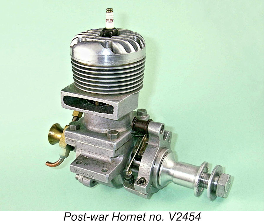
With the exception of its very unusual induction system, the Howler generally adhered to the “standard” racing engine design specification which had been initiated before WW2 in the Hornet 60 and had been further developed since that time. It featured cross-flow loop scavenging; a twin ball-race crankshaft; a twin-ringed light alloy high-domed baffle piston; a spark plug displaced towards the The Howler was built up around a set of four well-produced pressure die-castings. The upper crankcase, cylinder jacket and main bearing housing were cast integrally as a single unit. There were also individual castings for the crankcase rear cover, the cylinder head and the timer frame. Most unusually, the crankcase was split diagonally, with the six retaining screws being inserted diagonally to match. The rear casting secured in this manner comprised both the backplate and the lower portion of the crankcase. The name of the engine appeared cast in relief onto the back case cover. The engine featured a rather thin steel liner having the usual bridged ports to prevent ring snag. There was no exhaust stack – probably a good feature given the fact that all of the engine’s working air supply was drawn in through the exhaust ports. The provision of a stack might have resulted in a certain amount of residual exhaust gas being drawn in along with the fresh charge of air. The volumetrically-measured compression ratio of the Howler was a fairly healthy 9.5 to 1. The light alloy high-domed baffle piston was provided with two well-fitted rings. Although I didn't want to risk breaking a perfect head seal by removing the head to check, it's obvious that the underside of the head must be contoured to match the piston crown. Compression seal on my example is excellent despite the fact that the engine seems to have had very little running in the past to encourage the The appearance of the engine was notable for the absence of a conventional intake venturi. The crankshaft did incorporate a front rotary valve, but this drew fuel alone into the engine through a conventional needle valve mounted in a structure placed beneath the main bearing – there was no associated air intake. All of the Howler’s operational air requirements were met through the use of sub-piston induction. It is this feature that makes this engine unique in my experience. In functional terms, this resulted in the engine operating as a side-port design in terms of its air induction. The only operational difference was that the fuel was admitted to the crankcase through the separate front induction system and mixed in the crankcase rather than being mixed with the air in the intake. The fuel admission rotary valve drew fuel into an axially-drilled small-diameter central passage in the shaft, which discharged fuel to the crankcase through two opposed discharge passages formed in the crankweb. The designer appears to have relied upon centrifugal distribution to atomize and mix the fuel in the case. An obvious question which arises at this point is – why was this highly unusual arrangement adopted? Actually, there may have been some method to the seeming madness! In terms of air induction, a weakness of any conventional induction system is the need to restrict the area of the intake (however controlled) to a size which will both promote adequate fuel suction and facilitate the atomization of the fuel. Since the Howler's design separated the fuel and air induction processes completely from one another, the incoming airstream no longer had to combine these functions. Accordingly, the port area through which air was admitted could be made considerably larger than that of a conventional intake venturi.
The air admission area of the Howler was thus considerably larger than that of an equivalent unit having a conventional venturi. The design also side-stepped the friction, viscous drag and potential leakage of a conventional disc rear rotary valve (RRV) setup. It also created a very short and direct induction pathway for the incoming air. The downside of the arrangement was the fact that the overall air induction period was only 90 degrees - about half of that typically featured in a conventional racing engine. Moreover, the system was only fully open for a relatively small fraction of that period, although the substantially greater area might do something to compensate for this. Even so, it was probably the idea of increasing the intake porting area for the air while retaining adequate fuel suction that led to the separation of the fuel and air induction systems. Rather a clever notion, when one thinks about it! In effect, the Howler was a side-port engine on steroids! Certainly, both induction and transfer ports "pop" very loudly when the engine is turned over with the plug removed. Given its highly unusual induction arrangements, the engine’s timing figures are of considerable interest. The cylinder ports are timed fairly aggressively – naturally, the unusual induction system would not affect the functioning of those ports in any way. The exhaust opens at only 105 degrees ATDC for an exhaust period of 150 degrees, while the transfer opens 10 degrees later at 115 degrees ATDC for a transfer period of 130 degrees. These figures appear to be appropriate for relatively high operating speeds by 1946 standards. The sub-piston induction through which all of the engine’s air requirements are met opens at 45 degrees BTDC for a total sub-piston induction period of 90 degrees. Even though the exhaust ports are only opened part-way when TDC is reached, the engine still clearly has the capacity to induct plenty of air to support operation at low and mid-range speeds. Indeed, the open port area at TDC undoubtedly exceeds that which could reasonably be provided using a disc rear rotary valve (RRV) system. That said, the enforced symmetrical timing of the air induction phase might be expected to limit high speed performance. The figures that I was really interested in were those for the rotary fuel induction valve, which operates independently of the air admission function. One can't examine the functioning of this valve by looking down the intake, and I was unwilling to risk taking this seemingly well-assembled unit apart. It was therefore necessary to establish the opening and closing limits by other means. To establish the point of opening, I fitted a prop and connected an empty fuel bulb to the fuel nipple using some translucent fuel line. I then opened the needle valve and set the piston at BDC, pressurized the fuel bulb and slowly turned the prop until I felt the release of pressure in the fuel bulb, showing that the fuel induction system had opened. This began at 70 degrees ABDC, which was thus established as the point of opening. I then set the piston just above the point at which the exhaust ports first opened to initiate sub-piston induction. By squeezing the bulb, I found that the fuel valve was still open at that point - the air from the bulb could be heard clearly as it hissed into the engine and escaped through the exhaust ports. Turning the engine with the fitted prop, I found that the valve ceased passing air at exactly TDC. This was therefore the closing point. What this all means in real terms is that the fuel induction valve opens just after the transfer port closes. This makes perfect sense - suction can't commence until that port is closed, since the crankcase otherwise remains open to the atmosphere through the bypass. The fuel valve is thus about to open when the pressure in the case begins to drop as the piston rises with the exhaust port closed. It continues to be the only point of entry into the case until the sub-piston induction process commences some 65 degrees later. That's plenty of time for sufficient fuel to be drawn in during each cycle. However, there's a very obvious potential downside in handling terms. Since the air induction ports are closed for the first 65 degrees of the fuel induction portion of the cycle, 100% of the pressure reduction in the crankcase as the piston rises will be applied to the ingestion of fuel during that 65 degree period. From a fuel supply standpoint, the engine is in effect choked on every turn of the prop. Accordingly, every flick will draw a shot of fuel into the case, whether it's needed or not! I can see it not taking that many flicks to flood the case. A very quick start is definitely indicated if flooding is to be avoided!
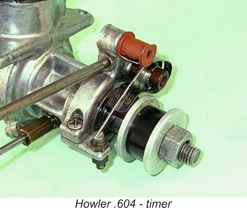
The well-made and sturdy timer is a typical automotive type mounted on a cast aluminium alloy frame, in keeping with standard big-bore racing engine practise. Both the timing and point gap are fully adjustable. As with any spark ignition unit, the other relevant timing figure for the Howler is the timer’s dwell period. This is the number of degrees of crankshaft rotation during which the points are closed, allowing electrical current to flow to the coil’s primary winding. Since a certain amount of real time is required to allow the coil to become fully saturated from an electro-magnetic standpoint, higher operating speeds require longer dwell periods. The downside is that longer dwell periods impose a greater drain on the ignition system batteries, since current will be flowing to the coil for a greater proportion of the engine’s running time. They will aso tend to promote higher coil temperatures. For a more complete discussion of the significance of this factor, see my separate article on the subject of spark ignition engine operation.
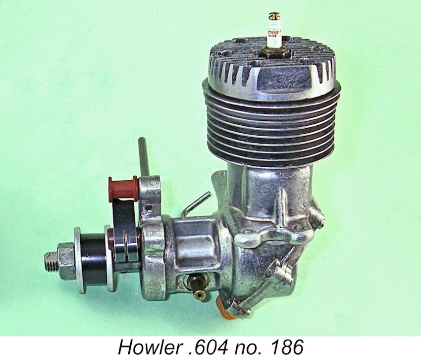
The entries for the Howler .604 in the late Tim Dannels indespensable’ “American Model Engine Encyclopedia” (AMEE) Volume 1 confirm that there were two variants of this engine. The vestigial intake structure of the 1945 model was plugged with a rivet, clearly seen in one of the above illustrations. The 1946 model was identical apart from having the intake structure drilled through at various hole diameters with no blocking rivet, thus allowing a degree of subsidiary crankshaft-timed air admission along with the fuel. Many of these later models had a revised head having fewer fins and a more rounded side profile. The other new feature for 1947 was the appearance of a twin-plug head on a few examples. These were probably an after-market option – they don’t appear to have been supplied as standard fittings. The first variant engines bore serial numbers – my illustrated example is no. 186. This is actually the highest serial number of which I’m currently aware, although it seems likely that the sequence went somewhat higher than this. The 1946 models do not appear to have borne serial numbers. Writing in his 1977 book “Collector’s Guide to Model Aero Engines”, the late O. F. W. Fisher stated that far fewer of the later variants were manufactured than the first model. According to the late Clarence Lee, writing in 1976 in "Radio Control Modeller" magazine (see below), only about 300 examples of the Howler were produced in total, explaining the engine’s relative rarity today. Fisher repeated this figure without acknowledging his source. Contemporary and Latter-Day Comments A fairly lengthy section covering the then-new Howler .604 appeared in the article by Edward G. Ingram entitled “Recent Model Engines” which was published in the June 1946 issue of “Model Airplane News” (MAN). Given the level of detail which it provides, the text of this article seems well worth quoting in full.
The comment may be interjected here that the quantity of liquid fuel ejected must also be affected by the speed of the engine, since the period of time the valve is open decreases as the engine speed is increased. This might be expected to result in too lean a mixture at high speeds. Tending to offset this, however, is the smaller amount of air inducted at high speeds because of reduced volumetric efficiency, and there is also the possibility that more liquid fuel will be taken in because of increased centrifugal action. Air enters the crankcase when the lower edge of the piston skirt uncovers a portion of the exhaust port on the up-stroke. When the engine is revolved in the reverse direction, a normal amount of air is taken into the crankcase, but as the fuel orifice then opens on the down-stroke, no fuel is drawn in, so a flooded engine may be cleared by giving the crankshaft a few reverse turns.
The Howler was listed once again in Ingram’s “Model Motor Symposium” (MAN, December 1946), albeit with no accompanying text. However, it was not included in Ingram’s later article entitled “Model Motors for 1948” (MAN, January 1948). The clear implication is that actual production was confined to the years 1945 and 1946. No attempt appears to have been made to develop a glow-plug version following the late 1947 introduction of that accessory by Ray Arden. The Howler was advertised in the December 1945 (right), January 1946 and February 1946 issues of MAN. The engine was also featured in advertisements placed by a wholesale business called the Holcomb Gas Model Supply Co. of Alma, Kansas in both MAN and "Air Trails". Holcomb listed the engine in their ads from February 1946 through to March 1947, although not in every advertising placement. The engine never appeared in the advertising of any other supplier. My sincere thanks to Gordon Beeby for digging out this information. After that, all was silent until the late Clarence Lee featured the Howler retrospectively in his "Engine Clinic" column in the July 1976 issue of "Radio Control Modeller" magazine. This article was very informative, although it added little or nothing to what has been presented above in the present article. The engine was also included in O. F. W. Fisher's previously cited 1977 book. Thereafter, the Howler was included as "Engine of the Month" in the late John Pond's column in the March 1985 issue of "Model Builder". Once again, this brief article added little or nothing to what has already been presented here, although John did mention that the Howler was also advertised in "Model Craftsman" magazine. The Howler .604 Evaluated - Almost! As far as I’m aware, the Howler .604 was never the subject of a published test in the modelling media. Accordingly, since I had a very nice complete and original example of the first model Howler .604 on hand, it appeared to be down to me to “boldly go where no man has gone before” by giving this interesting engine a few runs on the bench.
Seeming confirmation of my modest performance expectations came from the manufacturer’s published claim that the Howler would turn a 9x10 airscrew at around 11,000 RPM. The “Air Trails” test report on the contemporary Hornet 60 stated that the Hornet would turn a 10x10 prop (a heavier load, note) at 11,700 RPM. This pretty much confirms that the Howler was no match for the Hornet in performance terms. In contemplating a test of this engine, I was very mindful of the previously-noted fact that fuel will be sucked into the crankcase during every turn of the prop, regardless of whether or not the engine starts. It wouldn't take that many non-starting flicks to completely flood the case. This being the situation, I reckoned that it would be best to clamp the fuel line until a firing burst was achieved through port priming in the usual way. Once the thing was clearly ready to run, it would simply be necessary to remove the fuel line clamp prior to going for an immediate re-start.
To add insult to injury, the positioning of the needle valve in an updraft FRV location means that it will foul any test stand into which the engine is mounted, making mixture adjustment impossible. Given these cumulative challenges, I'm not at all surprised that very few of these engines ever get run! It was clear to me that the only way to resolve the mounting issue would be to make up a pair of strong bolt-on extension lugs which the test stand would be able to grip. This would not resolve the issue of the needle valve fouling the test stand, but that could be dealt with very easily by setting the needle valve in an "open" position and making mixture adjustments using a remote needle valve in the fuel line. All of this would require a considerable expenditure of time and effort on my part. Given the other matters commanding my attention at the time, I decided that this test would just have to wait. Given the near-new condition of my example, it was clear in any event that it would require a fairly lengthy break-in to deliver its best performance. I really couldn't justify the necessary expenditure of time, fuel and noise aggravation that this would require. I therefore decided that when I finally do get around to performing this test, I'll confine myself to trying the engine on just one or two props, purely in order to establish its handling and running qualities. I'll limit myself to a few very brief periods of flat-out running, keeping the engine running rich and retarded most of the time. I believe that an APC 11x6 prop would make a very suitable test prop for the Howler. Turning this prop at, say, 10,500 RPM would require the development of some 0.66 BHP at that speed. Frankly, I don't really expect much more from this engine. I would also use standard white gas/heavy mineral oil fuel. Most contemporary users would have done the same given that the Howler cannot legitimately be viewed as a true racing engine meriting the use of methanol/castor fuel. Moreover, I very much doubt that the downed airmen in that liferaft would have been supplied with methanol-castor fuel for their Howler-powered rescue helicopter! Anyway ................ stay tuned!! There's more yet to come! Summary and Conclusion It’s abundantly clear that the Bone Tool & Gauge Co, was facing an uphill battle from the start in trying to market the Howler .604 to the contemporary aeromodelling community. For one thing, the engine’s purpose was far from clear. Even with its high-quality structural specification, it clearly lacked the level of performance which would have been necessary to achieve anything approaching a competitive status as a racing engine. The contemporary Hornet, McCoy and Hassad opposition would have left it for dead.
Quite apart from imposing an uncompetitively-high selling price, that same high quality “racing engine” structural specification made the engine unnecessarily complex for sport flying applications. For such purposes, less complex engines of equal or greater (or at least adequate) performance could be purchased for significantly less money from other manufacturers. It's therefore scarcely surprising to find that only some 300 examples of the Howler ended up being manufactured and presumably sold. This sorry denouement had nothing to do with the engine’s quality – it was a very well-made product that was undoubtedly able to give good service to anyone who gave it a try. It was simply that it was an under-performer in a racing context; an over-designed unit in a sport flying context; and an uncompetitively-priced engine in either context. Seen in that light, its failure in the marketplace was inevitable. However, none of this detracts in any way from the fact that the Howler .604 was an extremely interesting and unusual design which reflected a healthy ability to think outside the box on the part of its designer Leonard E. Fowler. Anyone fortunate enough to acquire an example will find it to be a fascinating addition to their collection! Just let me know if you manage to get one running ............... ___________________________ Article © Adrian C. Duncan, Coquitlam, British Columbia, Canada First published December 2024 |
 In this article, I’ll share what little I know about one of the more unusual model engines to appear in America during the early post-WW2 period. I’ll be looking at the Howler .604 spark ignition motor which was produced in small numbers by the Bone Tool & Gauge Co. of Detroit, Michigan during the years 1945 and 1946.
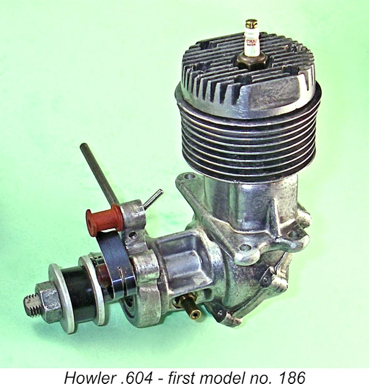
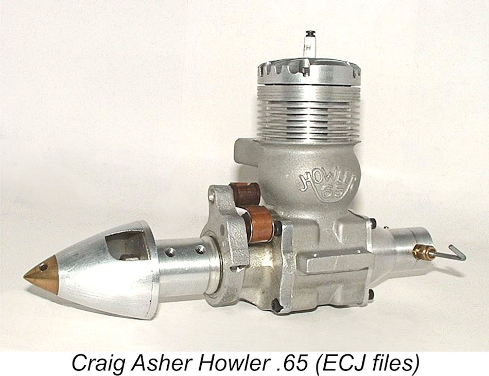 Before proceeding with the balance of this review, it’s necessary to deal with a matter that has created considerable confusion in the past. This is the well-known existence of a far later series of model racing engines dating from the early 1960’s and distributed under the Howler designation. These rear drum valve engines were designed by Craig Asher of Cincinnati, Ohio and marketed for the most part in kit form by World Engines.
 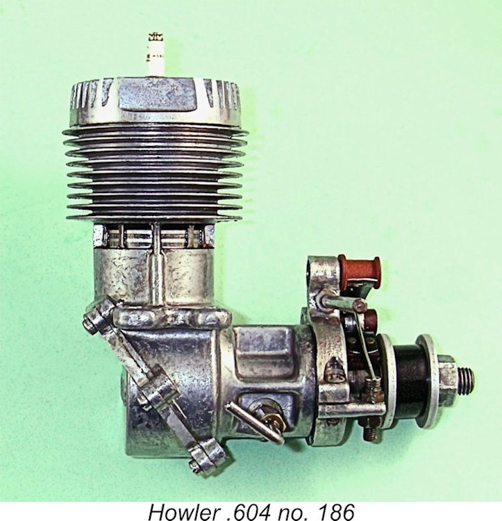 Bore and stroke of the Howler were 0.9375 in. (23.81 mm) and 0.875 in. (22.22 mm) respectively, giving a piston displacement of .604 cuin. (9.90 cc). Claimed weight of the engine was 13.03 ounces, a relatively low figure for a spark ignition engine of this displacement. My own illustrated example, engine no. 186, weighs in at 13.60 ounces (385 gm) - a little higher than the claimed figure, but not greatly so. Perhaps the weight quoted by the manufacturer was measured without a plug ...........
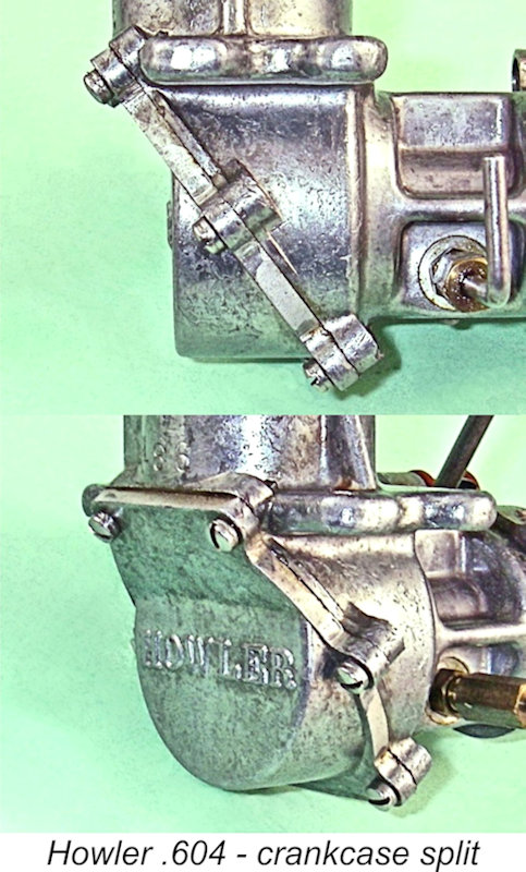
 rings to bed in. The piston drove the crankshaft through a rod made of heat-treated duralumin, with both small and big end bearings being bronze-bushed.
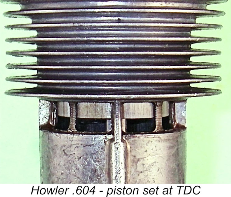
 “A feature of the Howler Class C engine, which is produced by the Bone Tool & Gauge Co., is what the manufacturer terms a “fuel ejection system”. Liquid fuel enters the crankcase by means of holes drilled in the crankshaft and crankweb. Fuel is conducted to a hole in the bearing housing. The hole in the crankshaft registers momentarily with the hole in the bearing housing once each revolution during the upstroke, so that a metered quantity of liquid fuel is ejected from the crankweb into the crankcase, where it spreads out and mixes with the air. It is stated that the quantity of fuel ejected is regulated by a needle valve in the fuel line.
 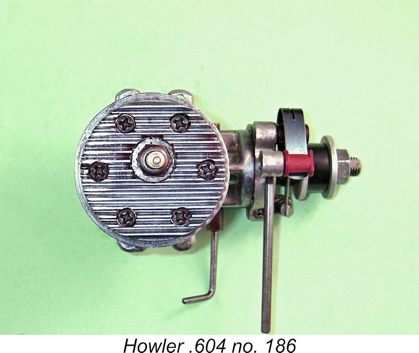 The cylinder and main portion of the crankcase are a single aluminium casting. A ferrous alloy cylinder liner is provided. The heat-treated duralumin connecting rod is bronze-bushed at both ends. Two combined radial and thrust ball bearings support the crankshaft, and the outer bearing is provided with a synthetic seal on each side. Two rings are used on the anodized aluminium alloy piston. The cylinder bore is 0.9375 in. and the stroke is 0.875 in., giving a piston displacement of .604 cuin. The engine weighs 13.03 ounces.
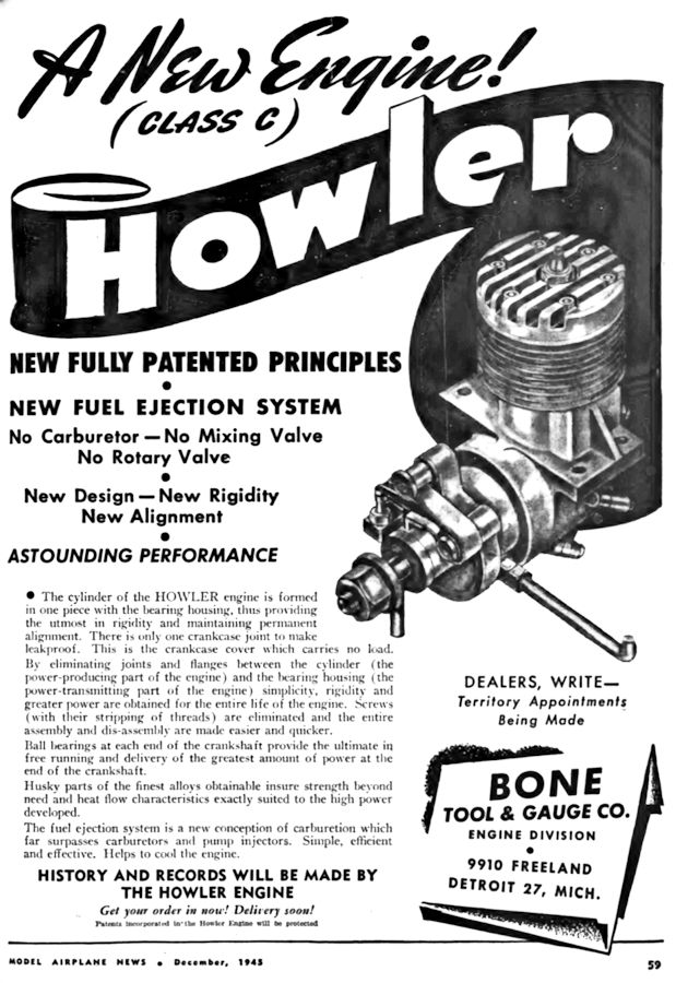
 Since it must surely be clear that this “modified sideport” design was never going to match its more highly developed rotary valve competitors like the contemporary McCoy,
 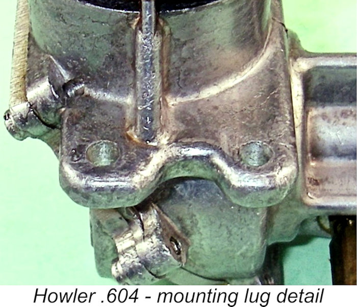 So ......on with the test, right?!? Well, this is where the old saying about the best-laid schemes takes effect! When I began to confront the challenge of mounting the Howler in a test stand, I was immediately presented with three highly problematic issues. The first of these was the fact that the engine's beam mounting lugs are of the notorious "mouse ear" type, a design which is inherently prone to failure unless very firmly secured. This is bad enough, but the two mounting points on each side are separated by stiffening webs which prevent the clamps of a test stand from being positioned close to the crankcase, as they have to be with this type of lug.
 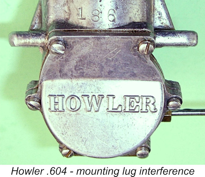 Even if this was not the case, an overriding issue was the fact that the side lugs which accomodate the two outermost backplate retaining screws protrude laterally well into the plan-view alignment of the beam mounting lugs. Accordingly, the test stand's clamp mounting blocks can't be brought close enough to the crankcase to allow a secure mounting, even if the aforementioned webs weren't present. This is a no-win situation!
 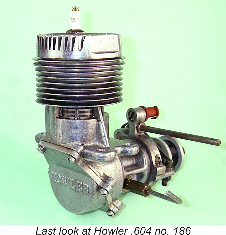 Despite this, the Howler's price matched that of many of its contemporary racing competitors. Indeed, the selling price of $34.95 which its specification and quality pretty much dictated was probably the final nail in the coffin lid of the Howler.
| |