
|
|
Detroit Drummies – the May Engines
While snippets of very useful information about many members of this series of model engines are scattered about among a number of issues of ECJ, Tim never got around to putting it all together in a single article. As if this wasn’t enough, the series completely escaped the attention of the late Ron Chernich on his now-frozen “Model Engine News” (MEN) website. This leaves it down to me to tell the tale! In doing so, I’ve relied heavily on the information regarding the May series which was gathered by Tim over the many years of his involvement with ECJ. The core of this information is preserved in the pages of Tim’s outstanding “American Model Engine Encyclopedia” (AMEE). Indeed, this is more Tim’s article than mine – all I’ve done is pull together a great deal of information which has been preserved entirely through Tim’s efforts. That said, any errors or omissions in what follows remain entirely my own responsibility. The May engines present a number of design features which place them well outside of the contemporary rut. Let’s get right into our review of their story! The May Engine Series – an Overview The May model engines were manufactured beginning in 1939 by a company trading as May Motors Inc. from an address at 7585 Russell Avenue, Detroit, Michigan. The principal behind this company has previously been named as one "George May", but a search of US Patent records (see below) confirms that his name was actually Ashton LeRoy May. Some much-appreciated genealogical research undertaken by my valued colleague Sheldon Jones (Tim Dannels' son-in-law) turned up a good deal of extremely interesting information about Ashton May. Sheldon learned that the May family had emigrated from England to Ontario, Canada around 1851. The first member of the family to do so was Isaac May of Cornwall, England. He had a son named Stephen Chesterfield May, who was born in Ontario in 1852. Ashton LeRoy May Sr. was Stephen’s son. He was born in 1880 in Ontario, but the family had moved to Detroit, Michigan by 1910. Stephen continued to live with his son until his death in 1930 at age 78. In 1910, Ashton LeRoy May Sr. established the Detroit-based “Screw Machine Products” company, becoming its President. His wife worked for the company as a book-keeper and stenographer. Their son, another Ashton LeRoy May and the future maker of the May model engines, was born in 1917. He grew up to become a machinist working for his father’s company. For clarity, I'll refer to him as Ashton Leroy May Jr. As most of my readers know, I simply can't resist a human-interest story conected with the history of model engines, and this one's a cracker! Ashton Jr. was evidently a “ladies’ man”! During the late 1930’s, while in his early twenties, he seems to have had an affair with Charlotte Holmes of somewhat distant Union, West Virginia, perhaps during the course of one or more business trips. It appears that he went through some form of marriage ceremony with Charlotte on April 7th, 1938. A son, Robert Lee May, was born to Charlotte only 6 months later on October 21st, 1938, suggesting that this may have been a form of “shotgun wedding” triggered by Charlotte’s possibly unplanned pregnancy. However, there was a serious impediment to ongoing conjugal bliss - Ashton Jr. was apparently engaged to Lucille Chilson of Detroit at the same time! Following the ceremony with Charlotte Holmes, he hurried back to Detroit to marry Lucille on April 28th, 1938 while still only aged 21 years. Clearly a fast mover – very light on his feet! If the marriage to Charlotte was in fact valid, the subsequent marriage to Lucille was undoubtedly bigamous! Be that as it may, Lucille gave birth to another son, Gilbert May, at some point prior to 1940. Ashton Jr. and Lucille continued to live in Detroit with their young son Gilbert at the residence of Ashton’s parents at 642 Gladstone Ave., Detroit, Michigan. Ashton Jr. was still working as a machinist for his father’s “Screw Machine Products” company at this time. Meanwhile, Charlotte had moved back to her parents’ home in Union, West Virginia. It appears that she didn’t consider herself to be formally married to Ashton Jr. since as of 1940 her son’s name had been changed to Robert Lee Holmes. Perhaps she already knew about Lucille. Reading between the lines, it appears that a crunch came in 1941 or 1942 when Lucille evidently found out about Charlotte and Robert Lee. This situation would have created great tension between Ashton Jr. and Lucille, giving her ample grounds for the divorce which came in September 1942. This left Ashton with Charlotte, who must have genuinely cared for him. She evidently wanted to regularize her relationship with him and legitimize their son Robert. She did so by marrying Ashton Jr. officially on December 3rd, 1942 in Detroit. The now-experienced bridegroom was still only 25 years old! Ashton Jr. died in 1966 at the age of 49, still living in Detroit. Perhaps he was a victim of his own "adventurous" lifestyle!! Charlotte married a second time in 1970 at the age of 52, eventually passing away in 2011 at the grand old age of 93. My very sincere thanks to Sheldon Jones for unearthing all this information! It appears that Ashton May Jr. began work on his series of model airplane engines in 1939 at the age of 22 following his "marriages" to both ladies. At this time, census records confirm that he and Lucille were both living at the residence of Ashton’s parents at 642 Gladstone Ave., Detroit, Michigan, which was the address from which he marketed the early engines. This address is located in a suburban area of Detroit which is exclusively residential and seemingly always has been. Ashton May Jr.’s workshop may have been located elsewhere, perhaps after hours at the premises of the "Screw Machine Products" company or possibly around the back of his parents' residence in the proverbial “garden shed”!
The May Motor had a displacement of 0.273 cuin. (4.47 cc). I’ve only been able to find one image of this model, and that image is of very poor quality. However, it does show the main features, and surely any image is better than none! The engine featured a sand-cast crankcase having very small beam mounting lugs with only a single hole apiece. The sand-cast upper cylinder housing seems to have encased a blind-bored steel cylinder, the emergent head of which was tapped for a 3/8-24 spark plug. This engine was not provided with an exhaust stack. The open timer frame featured the very vulnerable integrally-cast control arm which was to remain a feature of the May engines almost to the end. This model introduced the induction arrangements which were to become associated with the May series for its entire existence. As far as I’m aware, it was the first model engine to utilize an “inside-out” rear drum valve. In this arrangement, the interior of the drum was open to the atmosphere, with the induction port controlling access directly to the interior of the crankcase when open. In effect, a conventional crankshaft front rotary valve operating in reverse! The arrangement was to enjoy a period of favour some decades later in a number of very successful team race diesels of the 1960’s and 1970's. The May Motor was provided with a straight-back intake which protruded from the centre of the streamlined metal tank at the rear. This necessarily placed the carburettor fuel metering system entirely inside the tank with the Both the "carburettor-in-tank" and "inside-out" (or reverse) drum valve were undoubtedly quite novel ideas as of 1939. Ashton May was clearly aware of this - he was quick to apply for a couple of Patents covering the design of the May Motor and its immediate successor (see below). Both Patents were the subject of applications dated November 24th, 1939.
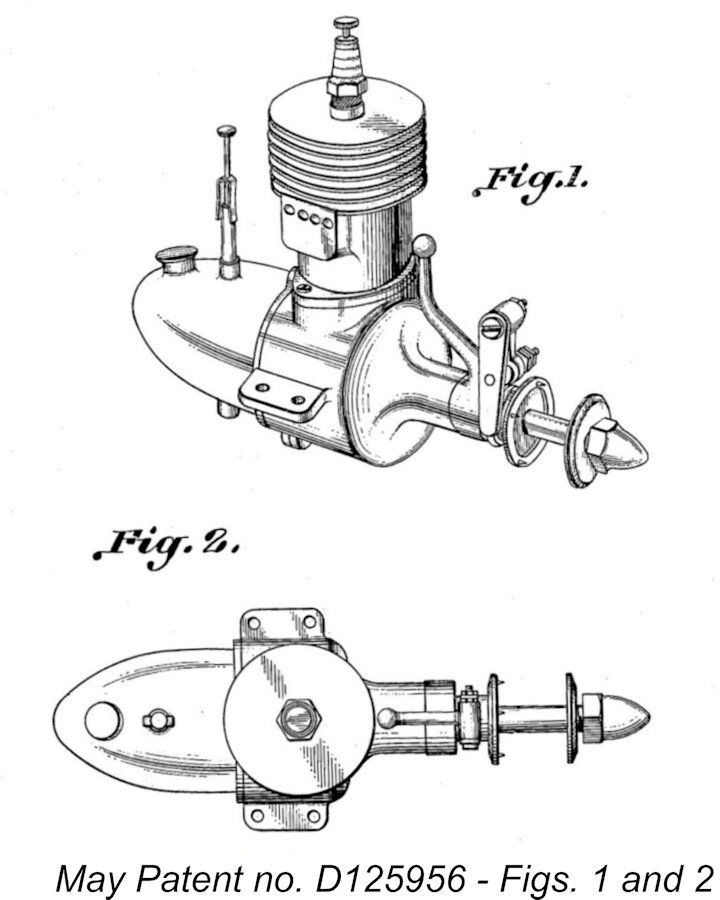
The other Patent, no. D125956, presents something of a puzzle! It relates very specifically to the "ornamental design" of the May Motor - basically, its appearance! I wasn't aware that a Patent could be issued for the appearance of a model engine - if it could, just about every maker who ever lived would be in trouble! I always thought that some kind of original design feature had to be involved. I can think of quite a few model engines that looked generally very similar to the May Motor! Be that as it may, the Patent was issued on May on March 18th, 1941. The Patent drawings (right) make it very clear that the engine concerned was the May Motor - there's no sign of an exhaust stack. It evidently didn’t take long for Ashton May to decide that a product having a somewhat larger displacement was called for. To this end, he built a few prototype examples of a proposed 0.453 cuin. (7.42 Following some testing of these sand-cast prototypes, dies were created to produce the cast components of future examples. Several die-cast test prototypes were produced using these dies. These latter units are sometimes referred to as “lead” engines because of the heavy dark-hued aluminium/zinc alloy used to test the dies. It is actually quite rare for experimental prototypes like these to survive, but the illustrated example somehow did so, ending up in the collection of late long-time Detroit resident and model engine builder George Hellmer, along with some of the other May engines illustrated here. It was more usual for test prototypes to be scrapped following testing. The illustrated prototype example has a slightly different cylinder, while no name is cast onto the exhaust stack. In addition, the brass tank is not plated.
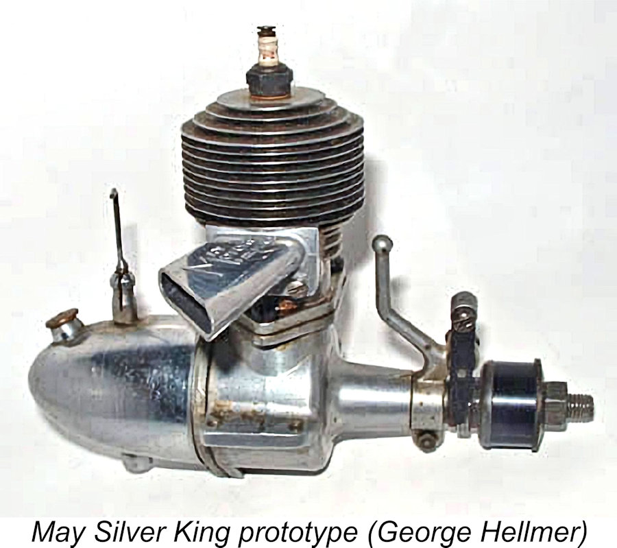
This carburettor was formed from a brass casting. It was soldered into the tank and sealed inside by a front plate which was recessed into the tank at the front, leaving the internally-threaded carburettor installation boss emerging at the center. The entire fuel supply system was thus formed into a self-contained unit with the carburettor enclosed inside the fuel tank. It was attached to the engine by being screwed onto an externally-threaded boss which protruded from the centre of the backplate and accommodated the drum valve. A thin The backplate had an integrally-cast ring of material around its outer rear perimeter which accommodated the front of the tank. However, this played no part in sealing the fully self-contained tank – it was merely included for aesthetic reasons. The drum valve was a suprisingly forward-looking design. The steel drum ran in a bronze bushing and was driven by a slotted plate which engaged with the rear of the crankpin. It drew mixture through its hollow centre which was open to the atmosphere at all times. The induction port was a round hole which engaged with the base of the upward-angled internal induction port to discharge into the crankcase. Timing was somewhat conservative - the valve opened at a quite reasonable 45 degrees after bottom dead centre but closed very early at only 15 degrees after top dead centre for a total induction period of 150 degrees. The mounting lugs were now provided with two holes apiece. In addition, the Silver King was provided with a long exhaust stack of aluminium alloy which was very neatly formed by die-casting. The stack was secured to the cylinder with two machine screws. The name “MAY MOTORS” appeared in relief on the exhaust stack’s upper surface, together with a reference to the still-pending patents. The outer end of the stack was sharply angled rearwards. The upper cylinder casting was attached to the lower crankcase with three machine screws. The Silver King cylinder castings featured small webs of material between the top fin and the next one down. These were eliminated during the production of castings for the later models, but it’s unclear exactly when this occurred since the cylinders remained interchangeable throughout. The Silver King engines all appear to have borne serial numbers. The previously-illustrated example displays the number 1128. Reader Paul Smigelski owns Silver King no. 1000. I thought initially that the sequence may have started at no. 1000, in which case Paul's engine would be the very first one off the line! However, a reader named Gerry posted on my blog site that he had engine no. 856, which appeared to be new and virtually unrun. So the jury's out on the number of these engines produced. More serial numbers, please!! An interesting aspect of the engine’s construction was the fact that the upper cylinder casting was formed around the blind-bored steel liner during the actual die-casting process. The manufacturer claimed that this It seems that Ashton May came to see it as being worthwhile to explore the possibility of simplifying this somewhat challenging cylinder production method. At some point along the way, he produced another interesting prototype based on the Silver King, as seen at the right. This had a blind-bored steel cylinder with integrally-machined cooling fins, replacing the steel-lined cast aluminium upper cylinder jacket used for the production models. It would appear that Ashton was insufficiently impressed to apply this change to the further production of the Silver King. Another unique feature of the May design was the piston assembly. The wrist pin was held inside the working piston shell in a separate yoke. This yoke was secured using a hexagonally-headed bolt which passed vertically downward through a hole in the piston crown to engage with a female thread in the yoke. So far, It’s clear that Ashton May intended his engine to be used for more purposes than just powering model airplanes. To that end, he introduced two additional models of the same basic engine. The first of these was a unit intended for model car service. It was designated the May “Model H” for some now-obscure reason. To accommodate the predominant orientation of the engine in car service, the exhaust stack was fitted with its outer end angled towards the flywheel rather than towards the carburettor. The same components were used, with the joint between the stack and the mounting flange amended to produce this orientation. No tank was provided, which left the cast brass carburettor completely exposed. This was the same casting that had been used in the Silver King. On these models, the extra “ring” of material used on the Silver King's backplate to streamline the tank fitting was machined off the backplates since it was no longer required.
The same flywheel-direction stack orientation was retained as on the car model, since marine models were almost invariably mounted with their flywheels towards the rear. The backplate machining and cast brass carburettor were identical to those seen on the Model “H”. Both the May “H” and “G” models were presumably supplied with flywheels. However, no authenticated May flywheels are known to exist – those featured on the relatively few surviving examples are owner additions.
Production of the May engines continued into 1941. Both the “Model H” and “Model G” were provided with slightly revised crankcase castings featuring mounting lugs which were both longer and heavier. Presumably the earlier lugs had been found wanting in the relatively stressful car applications, while manufacturing economy doubtless dictated that the same change be applied to both models.
At first sight, the revised tank location might appear to pose a potential handling problem due to the fact that it could only provide gravity fuel feed. The potential for flooding of the crankcase during starting seems at first sight to be rather high. However, the fact that the actual crankcase induction tract is oriented upwards at around a 60 degree angle (see earlier The one and only national advertisement for the May Rocket appeared in the March 1941 issue of “Model Airplane News” (MAN) as reproduced at the left. While this proves that the engine was certainly in existence by that time, it also suggests that production during 1941 was rather sporadic, perhaps due to the company gearing up for production relating to America’s increasingly-foreseeable entry into WW2. Only around 79 of these engines were reportedly completed before America’s December 1941 entry into the war effectively put an end to model engine production in the country for some years. It would appear that the efforts of May Motors were diverted fully into war production at this point.
The advertisement focused upon an engine designated as the Rocket “Victor Motor”. Since WW2 was still very much ongoing at this time, this name clearly represented the company’s view that victory was forthcoming (as indeed it was)! The advertisement acknowledged the engine’s heritage by stating (in very small print) that the engine was “formerly (the) May Rocket Motor”. An interesting observation is the fact that the advertisement made specific acknowledgement of the two previously-discussed Patents which had been issued in 1941 to Ashton May. Both of these Patents were clearly in effect as of 1945. Presumably the rights to these Patents had been part of the sale to the new owners. The Rocket Victor Motor was very little changed from the 1944 May Rocket design which had preceded it. Bore and As before, the upper cylinder casting incorporated the head cast in unit. It was fitted with a steel liner and attached to the crankcase with two screws. The piston featured the Rocket’s unique separate baffle and removable wrist pin yoke which were secured to the piston with a hex head bolt. The conrod was a steel stamping, while the crankshaft was a three-piece component having a stamped steel crankweb which was combined with the crankpin and main journal by a combination of swaging and brazing. The shaft ran in a steel-bushed main bearing.
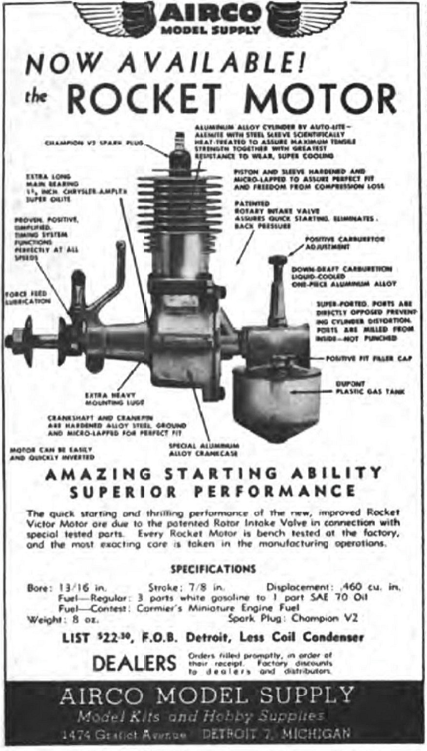
Interestingly enough, the Rocket Victor model was also simultaneously advertised nationally by a firm called Airco Model Supply of 1474 Gratiot Avenue, Detroit 7, Michigan. Their first advertisement appeared in the February 1945 issue of “Air Trails”, as reproduced at the left. It’s unclear how long the manufacture of the Rocket Victor model was continued by (or possibly for) Corporate Products Inc., but production appears to have been essentially confined to the year 1945. In late 1945 a further revised model appeared under the designation Rocket “4610”. This model exhibited a number of changes.
The former cast intake/tank top was replaced by an intake machined from hexagonal bar stock, which was used with the usual Rocket needle valve components. The engine no longer incorporated a built-on tank, but a separate cadmium-plated brass tank was provided, apparently being formed from a carburettor float chamber! This had to be mounted in the model adjacent to the engine. Finally, the Rocket “4610” was equipped with a revised timer which was fully enclosed. The new model undoubtedly represented an improvement over the previous Rocket offerings. Corporate Products Inc. were apparently a subsidiary of a company called the Detroit Regulator Co. which produced a line of gas regulators, also providing services to the local auto industry. In 1946 the parent Detroit Regulator Co. was purchased by former Boeing engineer Frank Kern Jr., who was initially very interested in the company's subsidiary model engine production, continuing this activity for some time.
Although the engine is unmarked for identification, structural details such as the bolt-on upper cylinder, 2-screw backplate attachment, rear induction, composite piston construction, crankshaft assembly and timer design combine persuasively to indicate a May/Corporate Products genesis. If asked for an opinion, I would incline towards a Corporate Products origin given the elimination of the bolt-on exhaust stack in favour of a more forward-looking integrally-cast feature, which suggests a late evolution of the basic May design.
As matters transpired, the .60 cuin. model (presumably intended to be known as the Rocket "5980") never advance past the prototype stage. Consequently, the Rocket "4610" was destined to be the final commercial offering in this series. It was presumably the late 1947 appearance of Ray Arden’s commercial miniature glow-plug that sealed the fate of the Rocket initiative. There’s no evidence that Kern ever contemplated moving ahead into the glow-plug era. Paul Smigelski shared an anecdote with me which, while unconfirmed, undoubtedly has a certain ring of truth. He clearly recalled reading this story somewhere but was no longer able to identify the source. Regardless, the story goes that in the late 1940's General Motors were in the process of developing what was to become the first overhead valve crossflow cylinder head V-8 automobile engine to appear post-WW2. They wanted to call this engine the Oldsmobile Rocket, but were taken aback to learn that the rights to the Rocket trade-name were held by Corporate Products!
Thereafter, Kern embarked upon a program of expanding the parent company's involvement with gas regulator design and production. In 1953 the company's name was changed to the Maxitrol Company (Maximum Control) to reflect this growing emphasis. The company became extremely successful - it remains very much in business today (2024), still using the Maxitrol name. The Rocket Models on Test
The review included one of the magazine’s outstanding cut-away drawings of the engine. Although the tested engine was identified as the “Rocket 46”, this drawing makes it quite clear that the subject was the 1945 Rocket Victor model, since the cast venturi/tank top and transverse open-frame timer are very much in evidence, while the cited bore and stroke figures confirm the 0.453 cuin. displacement. The engine’s construction was described in considerable detail, confirming the description provided earlier in the present article. Considerable emphasis was placed upon the need to set the timer correctly for starting – an inset image was provided to illustrate the point. In terms of performance, the article was a typical “Air Trails” effort in that the performance data supplied were both somewhat meagre and relatively un-informative. The only cited figures were 6,400 RPM with a 12 in. dia. high pitch prop (whatever that means – perhaps a 12x8?); 6,900 RPM with a “standard” 14 in. dia. low pitch prop (perhaps a 14x4?); and 7,300 RPM with a 12 in. dia. low pitch prop (possibly a 12x4?). Since we don’t have power absorption coefficients for these props, no estimates of power output can be developed. The major deduction is that the relatively small difference between the speeds achieved with the two low-pitch props suggests that the engine was running out of steam at around 7,000 RPM. Even so, we have to remember that this was 1945! The report writer stated that on the basis of comparative prop/RPM figures, the Rocket matched many of the .60 cuin. engines which had been tested, actually bettering some of them on the same props. Encouraged by this, Garami mounted the Rocket in a very large specially-designed model having a wingspan of 67 in. and a wing area of 525 in.2 for an all-up weight of 37 ounces. This model performed well enough that after some 50 test flights under power, the model was entered in a local contest. On the first official flight, the model was lost OOS after a 12 second motor run. Fortunately, it was recovered and returned to its owner in time to make a second official flight. On the second flight it was less lucky – once again it was lost OOS, but this time was never seen again! The report writer was duly impressed by the engine’s flight performance, stating that the motor appeared to be good for “a long life ……..and many good hours of flying”.
I therefore decided that I would confine my testing to a few rich and retarded break-in runs using a 12x6 Top Flite Power Point wood prop, with a brief lean-out near the end to gain an approximation of the engines' performances. My objective was purely to assess the engines' starting and handling qualities. For these test runs I used the mint-condition Champion V-2 spark plugs with which the engines were fitted as received - evidently the normal as-supplied factory fitting. The fuel was my standard classic sparkie brew of 75/25 white gas (Coleman Camp Fuel) and SAE 60 mineral oil (AeroShell 120) - methanol-based fuels can't be used with vintage plastic tanks. The sparks were supplied as usual by one of my ever-dependable Larry Davidson SSIGNCO units.
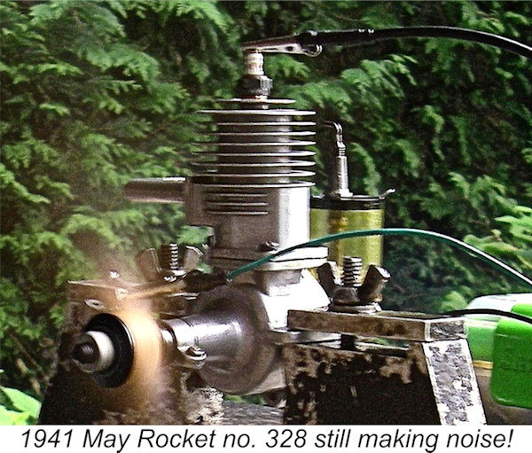
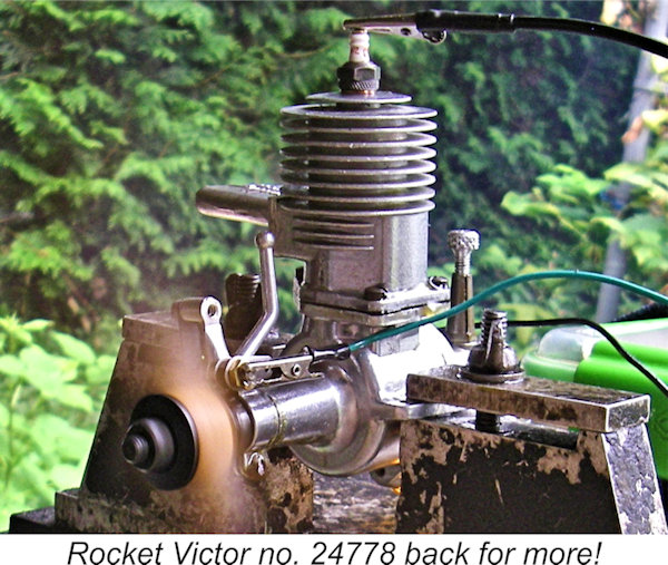
It turned out that this approach worked quite well. The engine was not what I'd call an "instant" starter - it was one of those engines which seemed to need just the right amount of fuel in the cylinder. Too wet, and it wouldn't even fire. I found that a prime administered with the exhaust port closed on the compression stroke worked pretty well - the transfer "pop" on the first flick over compression after the prime was administered got just a little fuel into the cylinder while blowing most of the excess back out the stack. Even then, it took a few flicks to get the conditions in the combustion chamber just right for starting. When a firing burst was obtained, I quickly opened the needle while the engine was still running off the prime. Since the running needle setting turned out to be only around 2/3 of a turn, the needle could easily be snapped open to the running setting, upon which the engine immediately picked up the fuel supply from the tank and kept going. Easy enough once figured out! That said, the engine proved to be Once running, the engine ran very steadily with a pleasant (to me, anyway!) throaty exhaust note. In view of its tight un-run state, I kept the needle and timer settings on the rich and retarded side. I put a few tanks of fuel through it in this manner, advancing the timer and leaning the mixture very briefly at the end of the last run. The engine turned the TF Power Point 12x6 prop at around 6,800 RPM, but it would doubtless do better than this if fully freed up and set more carefully. Even so, this isn't that bad by 1941 standards - around 0.274 BHP at this speed. Then it was the turn of the 1945 Rocket Victor. This one was even stiffer than its predecessor, clearly being in need of a good break-in if best performance was to be obtained. It exhibited the same fuel sensitivity for starting as the May Rocket, but the gravity fuel feed issue was eliminated by its use of an underslung tank providing suction feed - I could leave the needle at the best rich-running setting, which turned out to be around 1¼ turns. Apart from that, the same Once running, the Rocket Victor performed just as well as its companion, although it proved to be just as sensitive to the needle setting as its partner. I really appreciated the unusually throaty exhaust note, although the neighbours probably didn't share my enthusiasm! I enjoyed myself putting a few tankfuls through the engine with the controls set rich and retarded as before, although towards the end I did try a very brief period of leaner running with the ignition advanced a little. The Rocket Victor got the test prop up to 6,900 RPM (around 0.288 BHP), although I have no doubt that if fully run-in it would do a little better than this. Even so, if my previous deduction based on the "Air Trails" test that the engine likely peaked at around 7,000 RPM is anywhere near correct, the engine was running near its peak on this prop. On the basis of these admittedly skimpy tests, I'd say that the two engines both performed at completely satisfactory levels by the standards of their day. They are sturdy and well-made units which appear to have the potential to provide their owners with a fully acceptable level of dependable service. Conclusion My admittedly limited experience with the Rocket sparkies seems to be typical. General impressions among those who have witnessed members of the Rocket series running either in model service or on the bench are uniformly favorable. The late Tim Dannels stated that while he never ran one himself, he witnessed several examples being used in Old Timer free flight models. The examples witnessed by Tim did "quite well" in his recollection. My friend Wes Pettinger also never ran one, but reported that over the years he has seen several independent comments to the effect that the Rockets were "great engines to run". Their deep "throaty" exhaust note in particular drew favorable comment! Having experienced them for myself, I can see why!! ____________________________ Article © Adrian C. Duncan, Coquitlam, British Columbia, Canada First published October 2024 |
 I don’t know how I do it, but I somehow keep coming up with review subjects which have never been covered in depth in the pages of the late Tim Dannels’ much-missed “
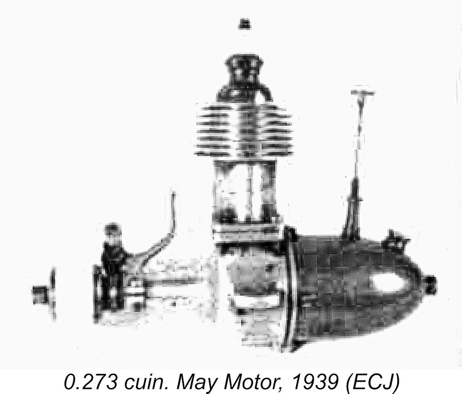
 The most significant of these two Patent applications was no.
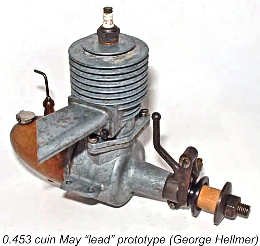
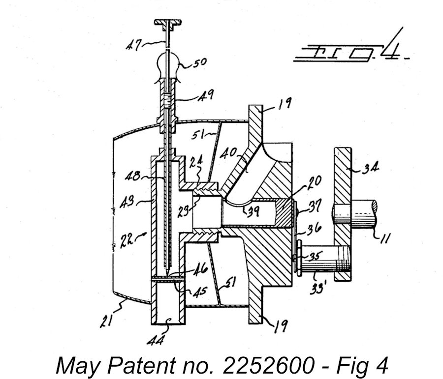
 The die-cast prototypes were evidently judged as being worthy of being carried forward to the series production stage. This led to the 1940 introduction of the 0.453 cuin. (7.42 cc) May Silver King. This model retained the “inside-out” drum valve of its smaller-displacement predecessor, but the design of the carburettor was changed. Instead of having a straight-back intake emerging from the centre of the tank, the induction tract took a 90-degree downward bend at the needle valve location to emerge from the bottom of the streamlined nickel-plated metal tank. This amendment to the original design was actually reflected in the application for Patent no. 2252600.
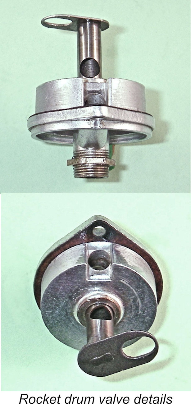
 improved the rate of heat transference from the bore to the cooling jacket. It would certainly have produced a tight interference fit! The ports were apparently formed by milling from inside the bore following this process, after which the bore was finished and lapped to size.
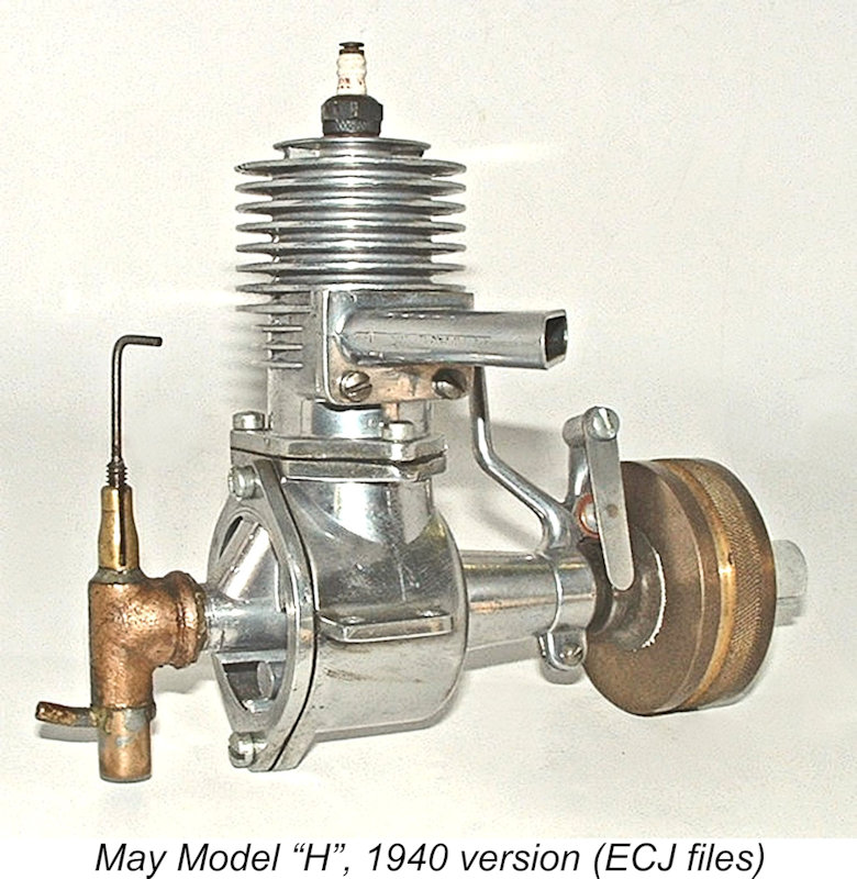 not that unusual back then. However, the piece de resistance of this assembly was the fact that the piston baffle was a separate sheet metal component which was also secured to the piston crown by this bolt! A somewhat Heath Robinson assembly, but it seems to have worked as long as the bolt remained tight.
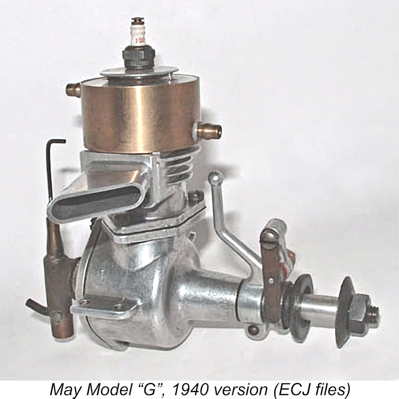 The other “specialist” variant was the equally obscurely-named May “Model G”. This was a marine version of the engine. Once again it was more or less the same engine, but was fitted with a water-cooling jacket which replaced the air-cooled finning. I don't have an example to check, but it appears that the air-cooling fins above the exhaust stack were turned off the upper casting, which was then threaded externally to accomodate a screw-on water cooling jacket.
 As of 1940, experiments with radio control had become increasingly prominent in American power modelling. The Radioplane experiments led by Reginald Denny of
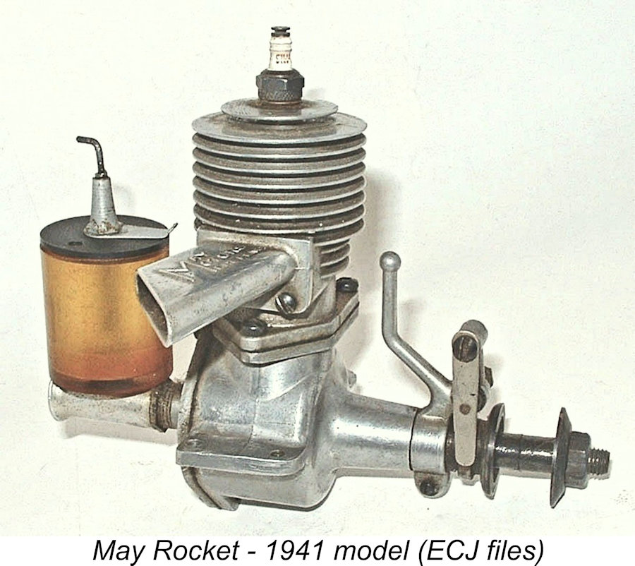
 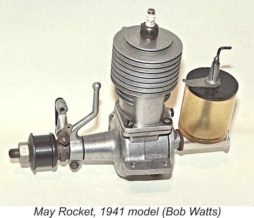 The big news for 1941 was the introduction of a replacement for the May Silver King aero model. This was the famous May Rocket 0.453 cuin. model. The main visible change was the replacement of the former streamlined metal back-tank with a machined straight-in induction tube having a large plastic tank mounted (or “perched”) on top and secured in that position by the needle valve assembly. The crankcase was of the new type with its more substantial mounting lugs. In other respects, the engine was more or less unchanged.
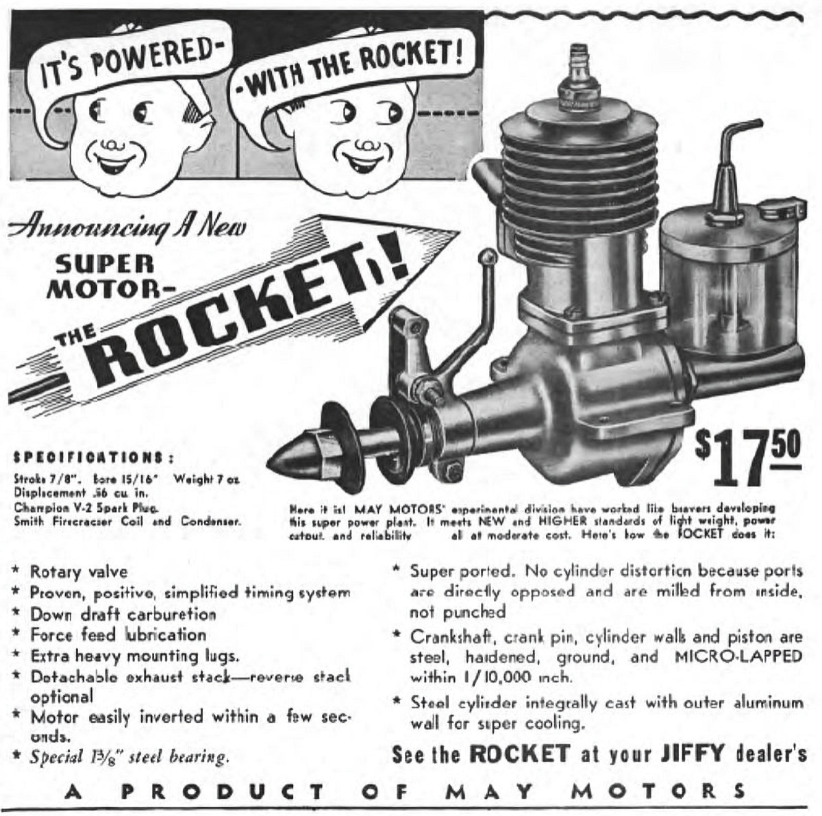
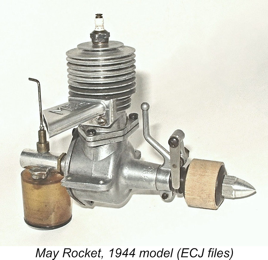 It wasn’t until 1944 that May Motors reappeared as model engine manufacturers. When they did so, their offering was basically the same engine as their 1941 May Rocket model, but the fuel supply system had been re-designed to feature a smaller plastic tank which was suspended below the machined intake venturi, still being held in place by the spraybar. It appears that the gravity fuel feed issue mentioned earlier in connection with the perched tank had indeed proved itself to be problematic, necessitating this change. The engine now featured suction fuel feed, which might be expected to create far fewer handling difficulties.
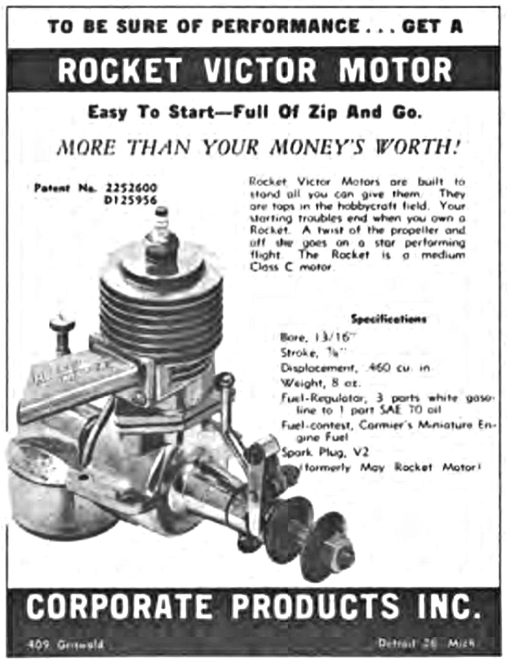 This was the last engine produced by Ashton May’s company, at least under his name. In late 1944 the May designs, name and goodwill were taken over by an entity called Corporate Products Inc., who were located at 409 Griswold Street, Detroit 26. This company’s first national advertisement appeared in the January 1945 issue of “Air Trails Pictorial”, as reproduced at the left.
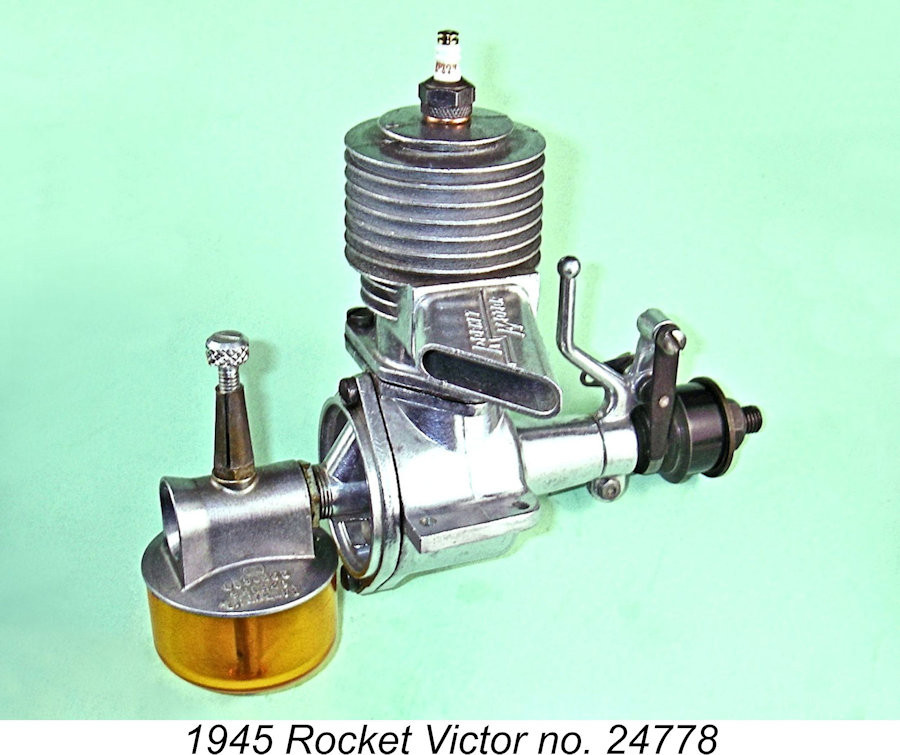
 A similarly-identified minor variant of this engine also appeared in very small numbers. This was essentially the same engine, but had a set screw in the bottom of the case to retain the main bearing. It’s possible that the company experienced problems with the steel bushing coming loose due to differential thermal expansion in a hot engine.
 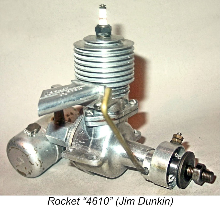 First, the bore was very slightly increased to yield a displacement of 0.461 cuin. (7.55 cc), up just a little from the 0.453 cuin. (7.42 cc) figure for the earlier Rocket models. The engine's name clearly reflects the revised displacement. The motivation for this change is unclear.
 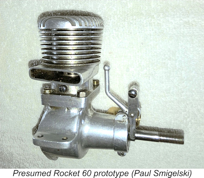 There is evidence in the form of a surviving incomplete example that a .60 cuin. design was brought to the prototype stage, perhaps at the instigation of Frank Kern. This example was found by reader Paul Smigelski of Detroit at a flea market in his hometown. Bore and stroke of this seemingly unique engine are 0.920 in. and 0.900 in. respectively for a displacement of 0.598 cuin. (9.81 cc).
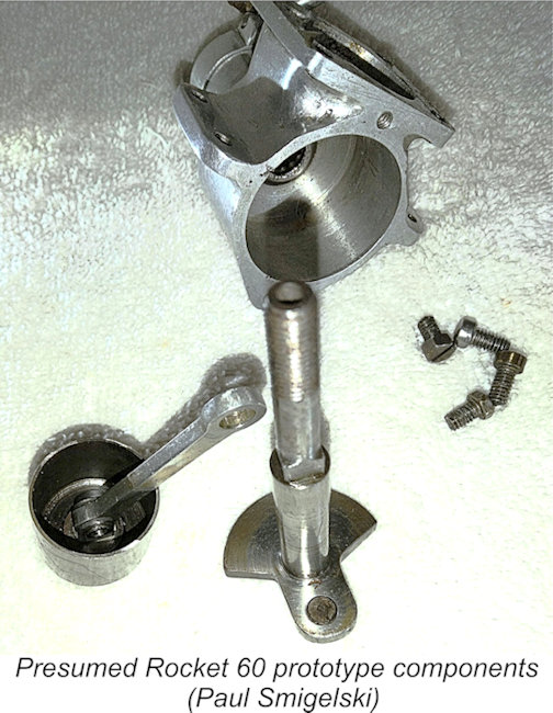
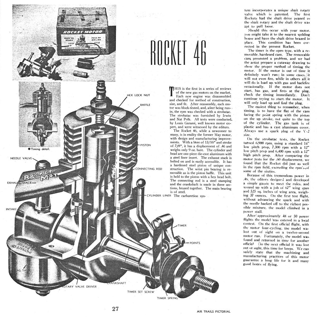 The sole published test of a Rocket motor appeared in “Air Trails Pictorial” in 1945 – I don’t know the month. It was actually the first engine to be included in the series of reviews published by this magazine. The test was conducted by the well-known power modeller Louis Garami, with the magazine Editors in attendance. A scan is attached for reference.
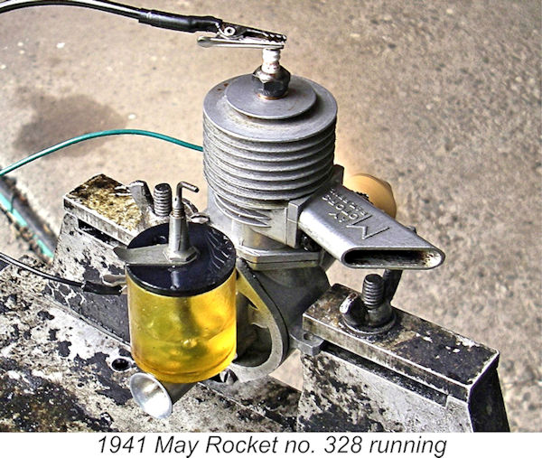
 First up was the 1941 May Rocket. Since the top-mounted tank would tend to drip fuel into the intake under gravity, I thought it best to begin with the needle closed and get the engine firing with no risk of inadvertently getting it flooded. Once it was clearly ready to start, I could open the needle to the required extent to get it going with no opportunity for flooding to occur.
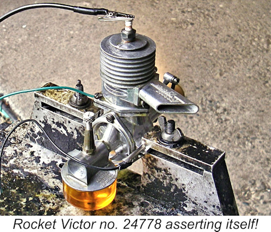
| |