
|
|
The Super Hope 60 by Adrian Duncan with Alan Strutt
Firstly, it’s necessary to recall that this displacement category had been very popular in Japan prior to WW2. O.S. made several such models prior to and during Japan’s involvement in that conflict, as did the Great Japan Model Aeroplane Co. Ltd. with their popular pre-war K-Class models in 5 to 10 cc (.29 to .61 cu. in.) displacements. There was doubtless something of a “hang-over” effect in play - the individuals involved resumed their activities by designing, building and flying what they knew. In addition, it appears likely that engines in this large-displacement category were seen as “prestige” or “flagship” products that underlined the technical credentials of their manufacturers. Indeed, a significant proportion of post-war Japanese big-bore models were “racing” designs which were clearly directed towards the high-profile competition classes in which such engines could compete. The post-war emergence of control-line flying undoubtedly accelerated this trend.
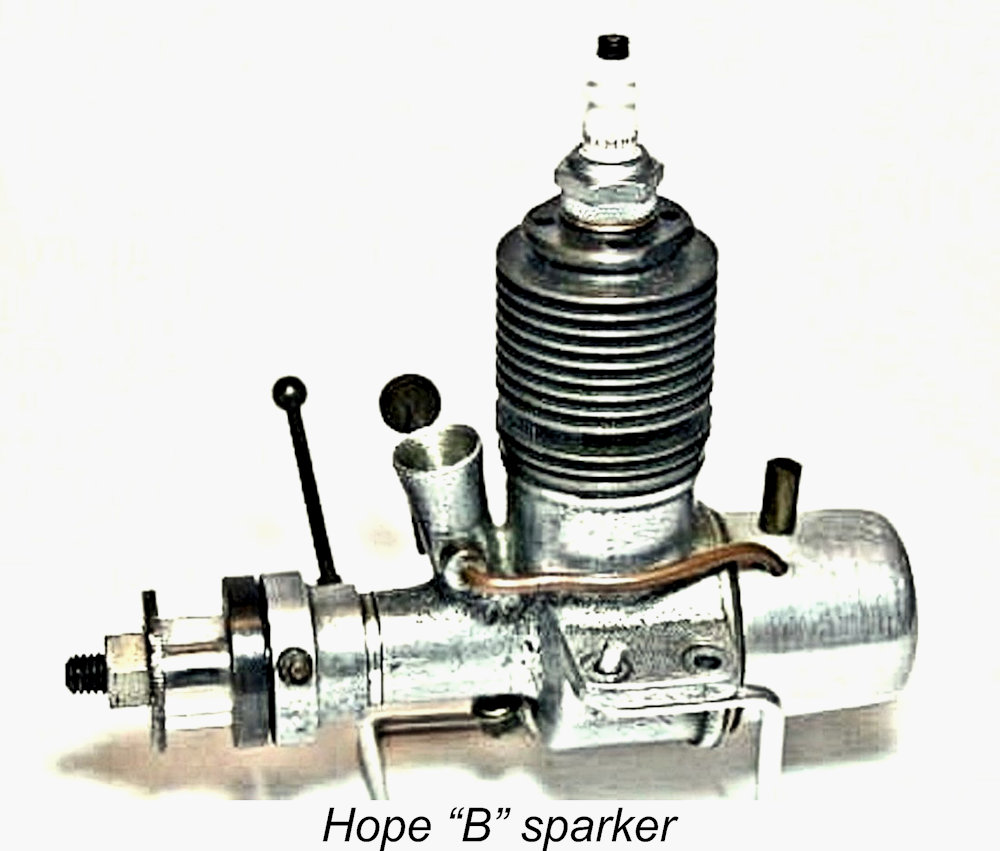
This point would be particularly emphasized if these engines could be showcased in the hands of Japanese modellers in successful competition with their American counterparts. It seems very probable that the achievement of competition success using Japanese engines in the hands of Japanese modellers sat right at the top of the priority list for the manufacturers concerned and that sales (or perhaps even donations) to leading Japanese competition fliers would have been their primary goal. Many enthusiasts are aware that O.S., Mamiya and Enya all entered the .60 cuin. racing engine field in the five years following the conclusion of WW2. However, they were by no means alone. Similar designs appeared under the Japanese TOP, Wasp, Super Devil, KO and Hope marques, although these efforts are far less well known. The present article will focus on just one of these lesser-known models - the Super Hope 60. Origins The The Hope company seems to have entered the model engine manufacturing field in 1947 with their .29 cuin. Hope "B" model which appears to have been a development of the early post-war Kotobuki 29. The Hope "B" straddled the late 1947 divide between spark and glow-plug ignition, appearing in both forms. With its radial porting and blind-bored cast iron cylinder, it was a very "Japanese" design of its time and place.
The Hope company’s entry into the field of big bore racing engines stood well apart from these "bread and butter" product lines. Various factors combine to suggest that the Super Hope 60 probably first appeared in early 1948. The engine appears to have been produced in very small numbers, making it an extremely rare unit today. Indeed, the very existence of Hope's entry into the very competitive world of post-war 10 cc racing engines seems to be one of the best-kept secrets of them all in the context of the Hope range.
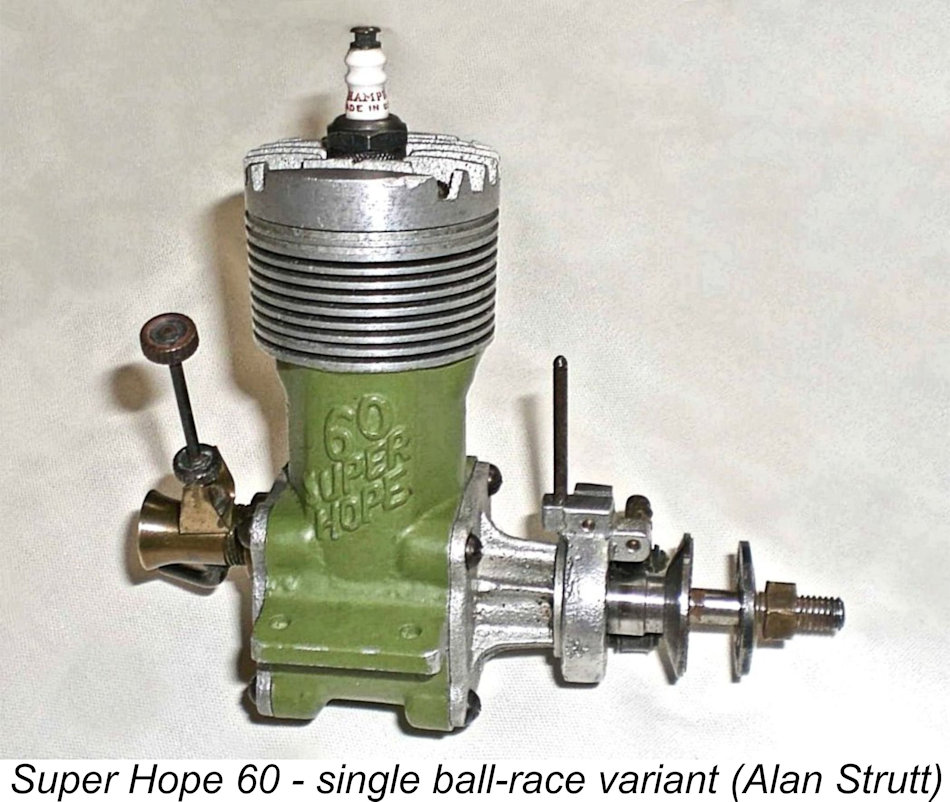
Like other contemporary Japanese racing units, these engines were doubtless created primarily for the use of Japan’s most capable home fliers. The apparent expectation was that these individuals would enhance the image of Japan by showing the occupying forces what the Japanese people could still do while enduring the unendurable. As if giving the finger to the world, the makers of the Super Hope 60 even painted their engines with what must have been leftover dark khaki paint, giving then an unmistakably militaristic aura.
However, while it may be fair to describe certain other Japanese engines of the period as clones, to describe the Super Hope engines as either clones or copies is to deny their essentially Japanese nature. Only if we were to accept the concept that a super sports car of today is a copy of a Ford Model T in that it has four wheels and an engine could we could legitimately argue that the Super Hope 60 is a copy of a McCoy 60 in that it employs a front housing, a central block and a rear housing that incorporates the induction system. With the above background in mind, it’s time to take a look at this very interesting engine. Description of Variants
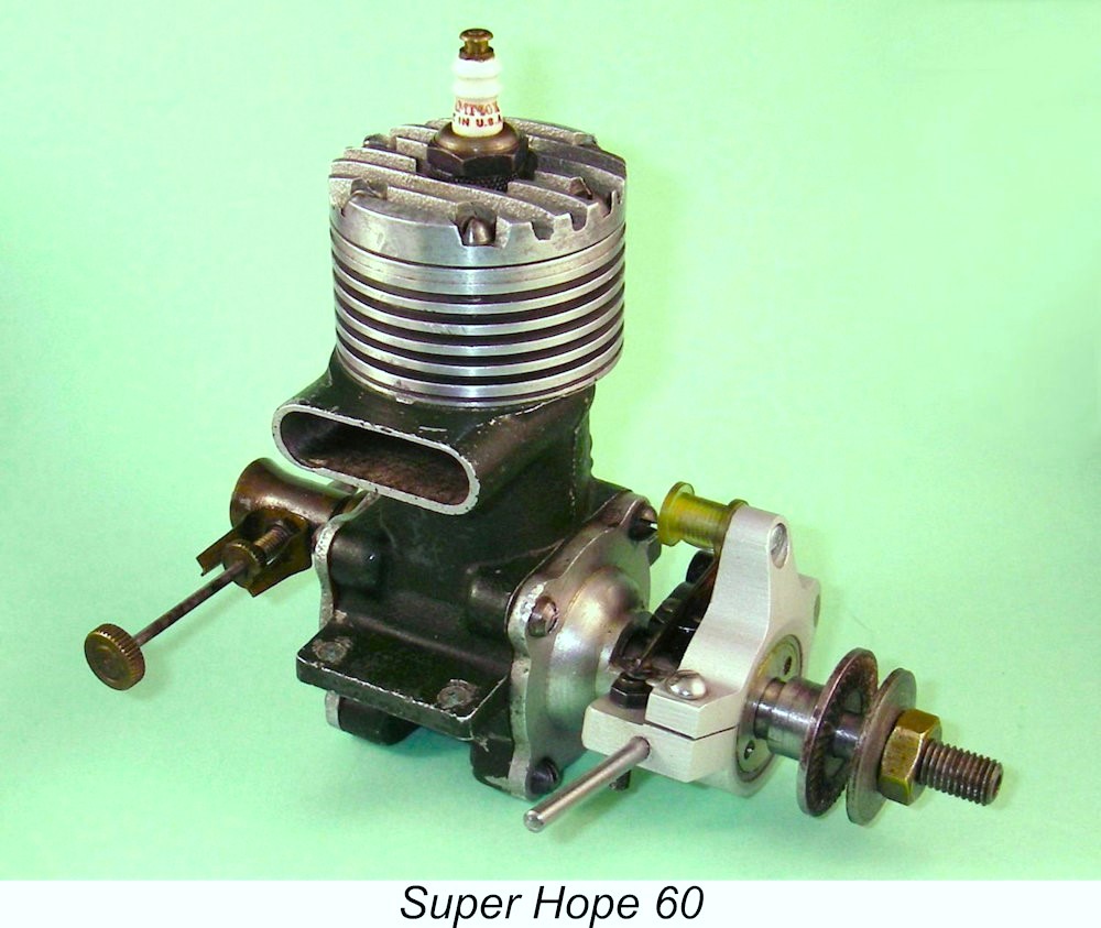
Subsequent to the article's original appearance, both Alan and I were each fortunate enough to acquire an additional example of this very rare unit. This happy circumstance greatly enhanced my ability to describe this engine and its variants, hence the major revision which is presented here. These two acquisitions bring the number of surviving examples of this engine of which I’m currently aware to eight - two owned by Alan, two sold from the collection of the late Miguel de Rancougne, two more of unknown ownership (of which the late David Owen kindly supplied images), one mounted in a tether car (see below) and my own subsequently-acquired example. Seven are (or were) constructed as spark ignition units, while only one was specifically intended for glow-plug operation, having no provision for a timer. As far as I’m aware, none of these engines bore any serial numbers - just the "60 Super Hope" identification cast onto the bypass. An inspection of the three examples for which first-hand information was now available revealed that the design details of the Super Hope 60 varied considerably between examples. I’ll begin with Alan’s original description of his own engine.
Beginning at the top, the cylinder head was an extensively machined sand-casting having widely spaced and very substantial fins along with a centrally-mounted 10 mm plug. The head was retained by six machine screws. In common with those used for retaining the front and rear housings as well as those found on the timer, these screws were all of a round-head slotted design (that is, with slot heads that are axially round and semi-circular in side elevation). This form of screw is very typical of the type of fastener used by Japanese engineering concerns before and during WW2. The use of such fasteners continued for some time into the post-war era until Japanese manufacturers were persuaded to change to crosshead Internally, the head was flat with a fairly large channel of semi-circular form machined into it to accommodate the piston deflector. The resulting combustion chamber shape was not such as to promote much in the way of "swirl" near TDC, and this too may be something of a limiting factor in performance terms, as it was in the early Nordec models. The engine was built up around a central sand-casting that incorporated the main crankcase housing, exhaust stack, bypass bulge and integrally-turned cylinder fins. The quality of this casting was good, as no imperfections were reportedly visible in the thin cylinder cooling grooves which were cut deep into the casting. Internally, the casting was extensively machined: the externally visible bypass bulge was machined internally by a circular cutter offset from the central line of the cylinder bore. Despite this, the cross-sectional area of the bypass was rather moderate for an engine of this displacement, probably representing a limitation to the engine's ultimate performance. The central block was painted in dark khaki green, a surface treatment which extended to the machined faces that mated with the front and rear housings. The identification "60 Super Hope" was cast in raised diagonally-oriented ciphers onto the bypass bulge. The tops of these ciphers were relieved of paint to make them stand out clearly. A cast iron liner was very closely push-fitted into this casting, the top of this having a lip around it that sat into a matching recess at the top of the block. The cylinder head was thus presented with a near-flat mating face which was part aluminium, part cast iron. A relatively thick aluminium gasket having the same external diameter as the cylinder at this point was fitted between the block and head to promote a dependable seal. The engine’s use of a lapped ring-less cast iron piston was another typically Japanese feature of the early post-war period. The large rectangular exhaust and transfer ports were sawn or milled through the cylinder walls, neither of these openings having any dividing pillars. The transfer port occupied approximately 90 degrees and the exhaust approximately 115 degrees of the cylinder's circumference. The cast iron piston was a typical pre-war Japanese design in that it had a flat top with a straight vertical deflector along with very thin walls featuring only a slight increase in metal thickness around the gudgeon pin holes. It was a superb fit in the cylinder, endowing the engine with excellent compression. While the idea of using ports cut in the lower cylinder and piston skirt to enhance or even in some cases enable gas transfer was much used in earlier Japanese engines (such as the many products from both the Great Japan Miniature Aeroplane Co. Ltd. and O.S.), this feature was not present in Alan’s example of the Super Hope 60. The 4 mm diameter gudgeon pin was made from solid steel with slightly rounded ends. It floated freely in the rather short iron piston bosses. The connecting rod appeared to be a sand-cast item which could best be described as being of "adequate" proportions. The casting at the big-end eye had been machined into a semi-circular shape: the big end eye was bushed with a brass or bronze-like material. In a fore and aft direction, the big-end eye extended further forward than it did backwards so as to ensure clearance between the rod and the crankweb counterbalance. This feature was to recur in other Hope designs. The rod was approximately oval in cross-section. The width of the small-end bearing was such as to completely fill the gap between the rather minimal gudgeon pin bosses within the piston. The crankshaft in Alan’s engine was a fairly lightweight item, machined in one piece. A hole was drilled down its centre line, presumably to lighten it. The thickness of the circular crankweb was relieved in order to form a modest counterweight opposite the crankpin. At the location of the crankpin, a hole was drilled through the web into the crankpin from the front, resulting in the crankpin being partially hollow. The end of the crankpin furthest from the crankweb was reduced to a rectangular bar to engage with the rear induction disc to drive it. A tapped hole was formed in the centre of the front of the crankshaft, presumably to facilitate the fitting of a spinner – a typical feature of many Japanese engines of the period. The propeller driver with its knurled face was turned from aluminium alloy and mounted on a shallow taper formed between the end of the bearing The front housings of both spark ignition and glow-plug versions of this engine appear to have been based upon the same sand-casting, which was machined nearly all over. It was arranged to accommodate the two ball races that supported the crankshaft. The front ball race was retained in place by an alloy cover that screwed into the front housing ahead of this bearing. The cover was clearly tightened using a tool akin to circlip pliers that engaged with two small holes lying across the diameter of the cover. It also served the function of keeping incidental dirt out of the bearing. The bearings themselves were both two-row ball races of the self-aligning type – relatively expensive items which offer further evidence of the care which went into these engines. A shallow annular channel of around 1 cm arc length was externally machined into the front bearing housings destined for spark ignition models. A bull-nosed grub screw was threaded into the timer body far enough to protrude into this channel. The channel and grub screw combined to limit the timer’s fore and aft movement on the otherwise plain housing, also limiting the available timing advance and retard. For the spark ignition variant, a sizeable segment of the surface of the metal "tube" that occupied the space between the front and rear ball race housings was machined away to provide the cam follower with access to the crankshaft. At this location, a smooth-edged cam profile was machined into the surface of the crankshaft.
If any legitimate criticism can be levied against the design of this engine, it’s the relative weakness of the front housing on the spark ignition variant that resulted from the creation of the access window for the cam follower, which assymetrically removed much of the cross-sectional area. If the front of this engine were to hit the ground at all hard, it’s difficult to believe that it would survive unbroken. This raises the possibility that this engine was in fact destined primarily for car use (then very popular). The tapered length of the crankshaft noted above would undoubtedly suffice to secure a flywheel. The glow-plug variant suffers no such weakness since the metal "tube" between the ball bearings referred to above is left whole.
The venturi assembly was turned from brass - another typically Japanese feature. It had a bore of 9.5 mm (0.374 in.). It was externally threaded at its delivery end to fit the tapped induction hole in the backplate, the intake end being flared into a bell-mouth. A knurled brass locking ring mounted on the threaded end of the venturi served as a lock-nut, allowing the venturi to be secured in any desired attitude to orient the spraybar/needle valve assembly as required. The spraybar was a simple one-piece item, threaded internally to accept the externally threaded needle valve. The needle itself was a standard Japanese design of the period, having a knurled brass disc which worked in conjunction with a hard brass "U" clip to retain the needle setting. A second knurled brass disc at the outer end of the needle provided a finger grip for making mixture adjustments.
While this engine cannot be viewed as a “wonder motor”, a great deal of care and thought clearly went into its design and construction. In terms of execution, the engineering was of the very highest quality and the equal of any contemporary western product - indeed, it was superior to many. There's no doubt that the creators of this fine engine cared deeply about what they were doing and put everything that they had into its design and construction. Turning now to my own subsequent acquisition, this example came to my attention in the form of an eBay offering of miscellaneous modelling bits 'n pieces, among which was a completely dismantled spark-ignition Super Hope 60! The American-based seller was quite honest about this engine – he stated very clearly that it had a broken piston and was missing its timer plus some other bits. However, the rest of the major components all appeared to be there and I reckoned that I should be able to cobble up a replacement piston. Accordingly, I decided to enter the bidding. This was admittedly a bit of a flier since there was no assurance that the engine could be successfully restored. However, I reasoned that this might prove to be the only opportunity that I'd ever have to own one of these very rare When the engine arrived along with a bunch of other stuff in which I had no interest, I immediately set to work cleaning up the parts and taking stock. It turned out that I'd done about as well as might reasonably be expected - most of the key components were not only present but in extremely good condition. There was evidence that the engine had done some running in the past, but not all that much - the lugs only bore faint evidence of a test-stand mounting, while the underside of the head was only lightly discoloured. The major issues were the fact that the piston had somehow been completely shattered and the timer was missing. In addition, 6 of the 14 original M3.5x0.6 assembly screws were also missing, as were all the gaskets. But everything else was there and in near-new condition. So far, so good……………! Interestingly enough, the front housing of this engine showed absolutely no evidence that a timer was ever mounted, nor did the cam surface show any signs of ever having been subjected to the rubbing of a cam follower. It is actually possible that this example never had a timer and was supplied at the customer's request for use in glow-plug form at a time when the company had not yet decided to produce a modified variant specifically for glow-plug operation with no provision for a timer. There's simply no way of knowing for sure. The complete destruction of the piston was a bit puzzling. There was no evidence of a disintegration failure during operation - pistons don't fragment in this comprehensive manner while running, and in any case a failure of this magnitude would undoubtedly have left its mark on other components. It looked more as if the piston had somehow been crushed while out of the engine. It's possible that a previous owner had set out to modify the motor and had tried to hold the piston directly in a lathe chuck or (shudder!) a vice! Or perhaps he simply dropped it and then stepped on it! Since the piston in these engines is of cast iron with extremely thin walls, it would not take kindly to such treatment. Most likely something like this occurred, upon which the owner gave up but thankfully kept the remainder of the engine components together in one box.
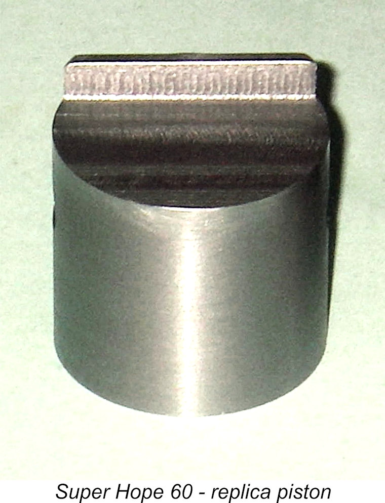
After making a quick 'n dirty aluminium mock-up just to check that my engine was compatible with Alan's dimensions (which it was), I was able to make an accurately-fitted replica cast-iron replacement. The one change that I made was to provide significantly longer bosses to support the gudgeon pin. Although I machined the rest of the piston down to logical limits as per the original, it still ended up weighing all of 17 gm - a lot of metal to shift back and forth at high speed, especially when compared to the McCoy 60's piston weight (with rings) of 11 gm! When assembled, the top of the cylinder in this example was deeply recessed into the upper crankcase casting. The spigot beneath the head was found to be some 0.030 in. short of making contact with the top of the cylinder when placed in position. Clearly there had to be some sort of fairly thick interface between the top of the cylinder and the underside of the cylinder head spigot.
I’m pretty confident that this (or something very like it) was the original arrangement. It would appear that the intent of this rather complicated set-up was to allow the user to vary the compression ratio through the use of spacer rings of varying thicknesses. A spacer of as little as 30 thou could be used and still provide enough overall thickness (spacer plus gasket) to ensure a seal. One could clearly go a long way in the other direction if desired. In addition, the recessed gasket is very well supported against blow-out forces. A very elegant arrangement - typical of the care that clearly went into the design and construction of this engine. With a 0.040 in. spacer installed, the compression ratio is roughly 7.5 to 1 by volumetric measurement - a bit low for high-speed glow-plug operation, but about right when running on spark. A switch to a 30 thou spacer would increase the compression ratio appreciably. Examination of this engine's components revealed several significant differences between this example and that originally described by Alan Strutt. Firstly, the number of cooling fins machined into the upper cylinder jacket section of the crankcase casting is different. Alan's engine had seven thin cooling fins between the band directly above the exhaust port and the thick upper flange in which the cylinder head installation screws were mounted. My subsequently-acquired example had only five fins, which were substantially thicker. So far, mine is the only example of this type of which I’m aware. Secondly, the plug thread in the cylinder head is 3/8-24 rather than the metric equivalent of M10x1.0 as in Alan's example. There was no evidence that the head had been re-tapped 3/8-24 through an existing 10 mm thread - this would leave visible traces as a result of the slight difference in pitch (24 tpi as opposed to 25.4 tpi) and would also result in a somewhat loose-fitting thread given the slightly larger major diameter of the 10 mm thread (0.399 in. as opposed to 0.375 in.). Since the thread in this example is a very accurate wobble-free fit to a standard 3/8-24 plug, it would appear to be the original size.
Further differences are to be found in the bore and stroke. The bore of my engine is 23.95 mm rather than the 23.50 mm of Alan's example - having made a new lapped piston for it, I can state this with complete certainly. The precisely measured stroke of my engine is 22.22 mm exactly, a little shorter than the 22.40 mm stroke of Alan's engine. These figures combine to yield a displacement of 10.01 cc (0.61 cuin). I suspect that we may be looking at nominal design bore and stroke figures of 23.9 mm and 22.2 mm for a nominal displacement of 9.96 cc (0.608 cuin.). The very small departures from these figures may simply represent “lathe operator’s license”.
The restored engine weighed 367 gm (12.95 oz.) with plug - a little less than Alan's example thanks to the absence of the timer. Alan sent me a drawing of the timer, from which my mega-talented friend Don Sohn was able to make the very accurate replica seen in the accompanying images, thus completing my engine. With the timer fitted, the engine weighed in at 392 gm (13.83 ounces) – 13 gm more than Alan’s example. Even so, this is very light for a spark ignition 10 cc racing engine of the period. The engine is also relatively compact by comparison with other contemporary designs. As previously noted, Alan's example of the Super Hope 60 did not feature the typically Japanese piston skirt ports and associated cylinder liner ports on the transfer side. However, both the cylinder liner and the remaining shards of the original piston made it clear that my later arrival did have such ports, which appeared to be original as opposed to owner modifications.
This feature should confer a number of benefits. The most obvious is an improvement in transfer efficiency due to the improved gas access to the upper bypass passage. However, that's by no means all - the piston ports would also improve piston cooling by promoting the flow of cool incoming mixture through the piston interior. They would also promote better lubrication of the more heavily-loaded transfer side of the piston skirt, which absorbs the side-thrust generated during the power stroke. Finally, they would remove a fraction of reciprocating weight - an important objective with a cast iron piston. Overall, this appears to be a very worthwhile improvement.
The method of construction is uncertain, but an educated guess can be made. There's no sign of a "seam" inside the small hole which is machined into the centre of the crankshaft, presumably to lighten it, so it would appear that the rear portion of the disc must feature a lengthy central spigot which is pressed into a hollow section of the crankshaft journal. A pair of bronze rivets are used to maintain the two components in a fixed annular relationship following installation. As in Alan's engine, the crankpin is internally drilled from the front at the crankpin location, presumably after assembly of the shaft.
However, another issue with which the designer was clearly concerned was pumping efficiency. At the time, the way to achieve good pumping efficiency was to keep crankcase volume down to a minimum (no tuned pipes back then!). The Hope designer had gone to a lot of trouble to do so - the very thin and rather complicated disc valve is an example. The Super 60 has a commendably small crankcase volume, pumping with great enthusiasm when turned over without a plug - the transfer port opens with a real crack! The designer evidently wanted to keep it that way. Geometric considerations meant that there was little opportunity to increase the size of the visible counterbalance on the web. But adding cutaways on the crankpin side in the conventional manner would increase crankcase volume. So what to do? Simple in concept - hollow out the web internally on the crankpin side. This would achieve the goal of improving the balance factor without adding to the crankcase volume. Fair enough, but how? Well, by making the counterbalance section of the web (with the crankpin) a separate component which can be machined from both sides! I'd put money on it that if one were to split the components of the crankweb (I'm not volunteering!), one would find two circular cavities end-milled into the invisible faces of those components - one on each side between the rivets and the crankpin. This would substantially reduce weight on the crankpin side, hence increasing the degree of counterbalance in the crankweb as a whole. However, it would do so without increasing crankcase volume since the two cavities would be isolated from the rest of the case. It's actually also possible that there could be similar cavities on the counterbalance side with lead discs inserted into them. This idea is not unique - readers may recall that the K&B Series 61 and Series 64 racing engines had internally-hollowed crankwebs. In their case, however, the webs were in one piece with milled slots on the crankpin side. The slots were isolated from the rest of the crankcase through the use of a shrunk-on aluminium band around the crankweb perimeter. Same idea, though. Naturally, without dismantling the crankshaft on this example I can't prove any of this. But the crank "feels" to be considerably more heavily counterbalanced than its appearance would suggest, and this is the best idea that I've been able to come up with to explain the use of composite construction. If anyone has a better idea, let's hear it! It's impossible to say for certain in which order the divergent features seen on this example and Alan's originally-described engine appeared. In my personal opinion, my engine seems more likely than not to be the later of the two. My basis for saying this is that it seems to embody some degree of design progression compared to Alan's example. In particular, I can't see them starting out with piston ports and then eliminating them from what was clearly intended to be as good an engine as the makers could produce at the time in question. The composite crankshaft too seems to be a sophisticated response to a demonstrated vibration issue if it is indeed motivated by balance considerations, as I think likely. But these are merely observations - in themselves, they prove nothing. Apart from the above-noted departures, my engine appears essentially identical to Alan's example. The timing of the disc valve appears to be the same as that of Alan's unit - around 40° after bottom dead centre to some 30° after top dead centre for a period of 170°. Cylinder port timing is also fairly conservative by racing standards - the engine features an exhaust period of around 140° combined with a transfer period of approximately 125°. However, a few more highlights emerge from a close examination of the engine. The prop driver on this example is steel as opposed to aluminium. Other little details leap out at one which reflect the level of The steel disc valve is a work of art with its extensive machining for mounting and balance purposes and the straight trailing edge on the induction aperture which keeps it fully open a little longer around top dead centre and then gives quite rapid closure. In conjunction with the generous 9.5 mm (0.374 in.) dia. intake venturi, one would expect this valve to work very efficiently. The disc is mounted on an integrally-machined 4 mm steel spigot which runs in a plain bearing in the rear cover. The number of machining operations required to produce this single component is noteworthy. Having made one myself, I can attest to the fact that the piston also requires an unusually large number of machining operations and multiple set-ups. This component alone would have been an expensive item to manufacture. However, like the composite crankshaft, the twin-row self-aligning ball bearings and the carefully-engineered disc valve, the makers skimped nothing when it came to producing this engine - if a feature was considered to be functionally necessary, they included it regardless of cost or complexity!
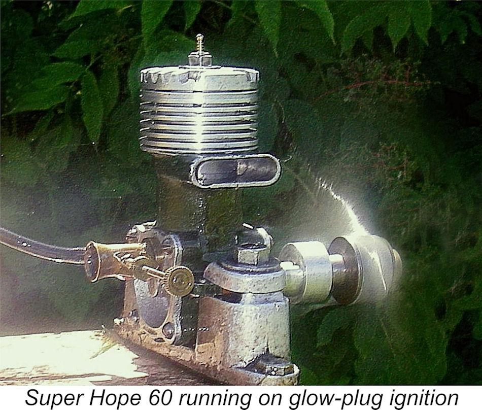
After I made the piston, the required gaskets, the head spacer and the missing head screws, the engine went back together very nicely. With a 3/8 in. Champion spark plug fitted, it looked really striking with its dark olive-green case offsetting the machined aluminium surfaces. While waiting for the arrival of Don Sohn’s superb replica timer, I gave it a few rich runs using glow-plug ignition, finding it to be a very easy starter which needled extremely well. The compression seal provided by my replica piston was outstanding. The subsequent addition of Don’s replica timer completed the engine's appearance very convincingly.
I would have liked to explore the engine's performance potential on a methanol-based fuel, but the relatively tight replica piston dissuaded me from doing so. I judged that it would take an hour or more of additional running to free things up to the point where the engine could safely be run flat out on a lean mixture with advanced ignition. Since I had no plans to fly the engine, I felt that this exercise would be both unwarranted and unwise for conservation reasons - why risk beating up on a rare survivor like this one? I contented myself with having demonstrated that my replica piston would undoubtedly work itself into a perfect fit with more running time and that the replica timer worked as well as it looked. I also learned that the engine was an unusually sweet-handling unit for its type.
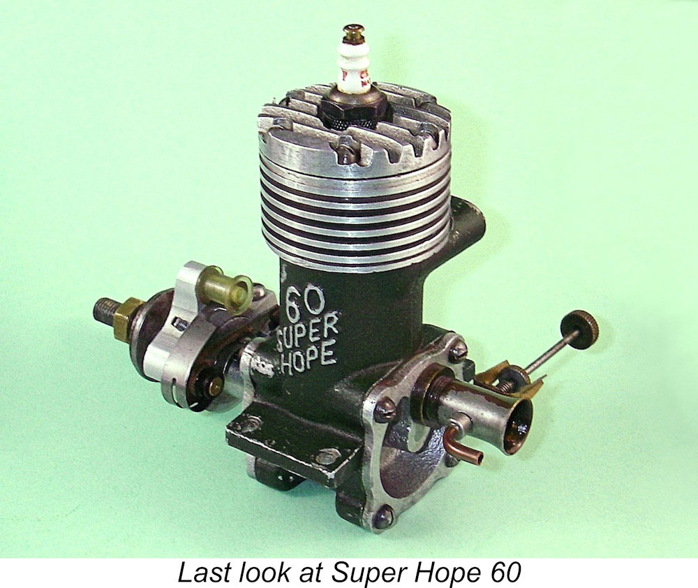
Furthermore, the makers of the ROC .049 glow-plug motor of 1950 supplied otherwise-identical engines displaying the SMITH name in place of the ROC identification. Finally, a pan and gearbox for a SMITH tether car appeared on eBay some years ago. It's clear that a completely undocumented range of model goods was traded in Japan under the SMITH name, making the claimed association of Alan’s engine with a SMITH car entirely credible. If anyone knows more about the SMITH marque, let's hear from you! The most unique structural feature of this example was its completely different front housing incorporating only a single Other immediately obvious details of Alan's acquisition were its pale green crankcase and the fact that it had been assembled with the exhaust stack on the left. This latter feature mirrored the orientation of the engine mounted in the illustrated tether car. Alan was quite certain that the pale green colour was a repaint – he considered it to be more than likely that it was originally painted in Hope's trademark dark olive green drab. The similar engine mounted in the illustrated tether car is painted in this way, supporting Alan’s opinion. The crankshaft in this engine was once again completely different from that of either of the examples described earlier. The front diameter of the crankshaft was smaller, being threaded 6 mm instead of the 7 mm seen on other examples. It was also slightly shorter. In addition, the centrally-drilled hole in the shaft at the rear was absent. The crankweb was a one-piece item having both a counterbalance and a pair of cutaways, one on each side of the crankpin. Another serious attempt to improve the engine's balance factor, albeit in this case without resorting to the trickery of a composite shaft to minimize crankcase volume.
The cylinder porting was very different from the other examples described earlier. The exhaust was divided into two elongated-circle “race track” openings separated by a dividing bar located centrally between them. Most oddly, the transfer port consisted of a horizontal row of 5 drilled holes in place of the large rectangular opening described previously. The engine also lacked the piston ports seen on my own example. Overall, it appears that cost considerations may have been a factor in the manufacture of this variant. Further differences were to be found in the cylinder head. On this variant, the head was retained by only 4 screws, a seemingly retrograde move when one considers the sealing problems that Mamiya experienced with their own racing 60 using only 4 screws. On the plus side, the plug location is offset The brass intake venturi was of similar construction to the others but the distance between the end of the installation thread and the spraybar was reduced. Together with the shorter crankshaft mentioned earlier, this contributed to a reduction in the engine's overall length of some 5.3 mm. It must be said that this engine presents us with an odd mix of retrograde and forward-looking features. The more advanced head design suggests that it is the latest engine in the known series, in which case we might suspect that the various simplifications noted in connection with the piston, cylinder porting, head fixing, main bearing and crankshaft were cost-cutting measures. If so, this would be the first time that Hope had ever displayed any concern over cost in connection with the Super Hope 60! It may be that they were contemplating putting this version into series production - we'll probably never know. The really significant point about all of this is that no fewer than four distinct variants are represented within the group of eight engines of my present acquaintance - three spark ignition designs and one purpose-built glow-plug model. This is an unusually high proportion of distinct variants in such a small sample. The implication is that the manufacturers were not working to a fixed design. Instead, they were forever tinkering with the design with a view to improving performance, or perhaps in response to individual customer requests. This reinforces my view that these engines were "manufacturer's statements" rather than production engines per se. If there were ever plans to put this engine into series production, it would appear that they came to nothing. It seems unlikely that manufacture continued into 1950. Conclusion
The numbers produced were relatively small, but those that did find their way into the hands of active modellers would have served their owners well. They may not have been the most powerful racing 60’s of their day, but they did make an emphatic statement regarding the design and manufacturing capabilities of the Hope Engineering Company. This brings the story of the Super Hope 60 up to date as far as I’m able to present it at this point in time (2023). If anyone out there is in a position to add to this shared knowledge, let's hear from you! All contributions gratefully and openly acknowledged! ________________________________ Article © Adrian C. Duncan, Coquitlam, British Columbia, Canada First published on MEN September 2009 This revised edition published here December 2023
|
 In an earlier series of articles on Ron Chernich’s “
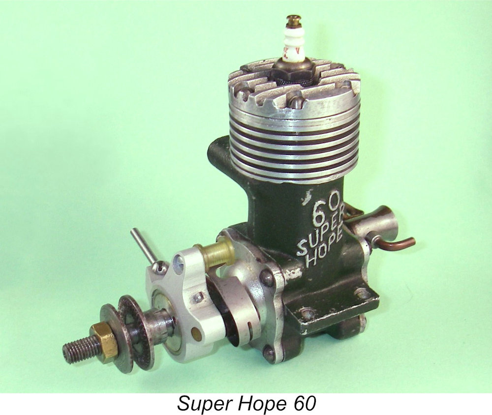
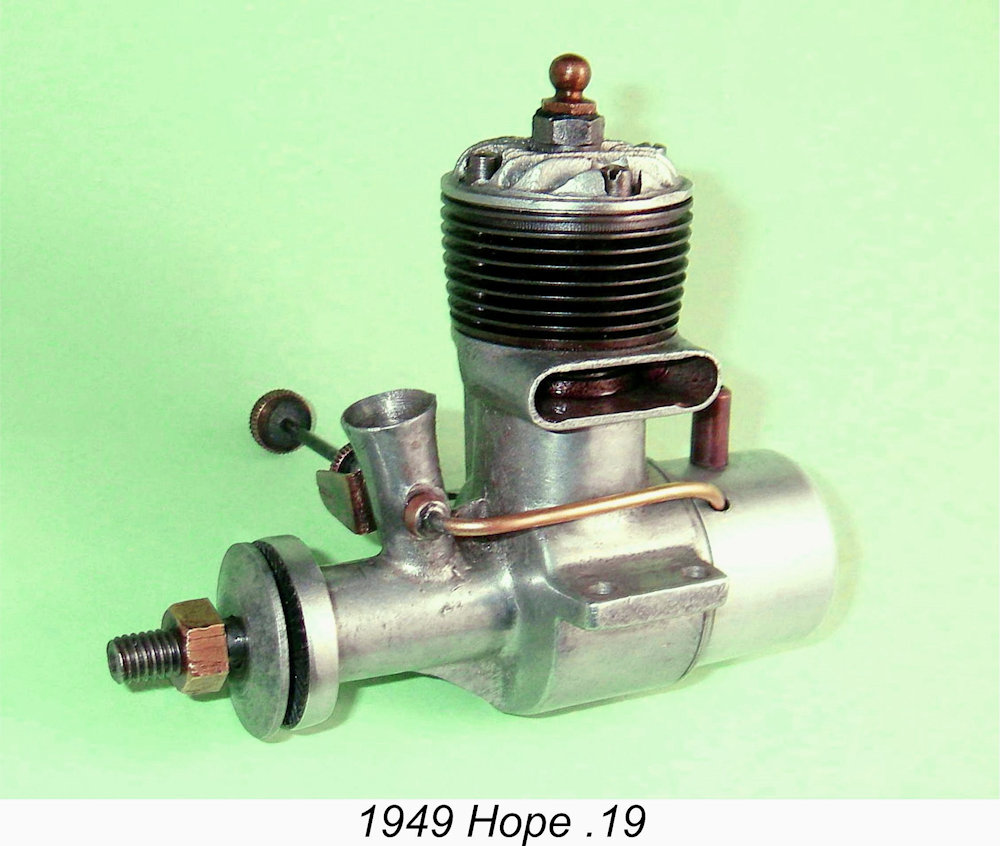 In 1949 the Hope company initiated a move to modernize their range through the introduction of a sand-cast .19 cuin. model of far more "International" design. This abandoned radial porting in favour of the more fashionable cross-flow loop scavenging with a separate cylinder head attached by screws. The .19 was followed in due course by further similarly-designed models in the popular .09 and .29 cuin. displacement categories. All of them were basic no-frills plain bearing sports engines of their era, being made to a very good standard at a highly competitive price. Full details will be found in my earlier series of articles on the
 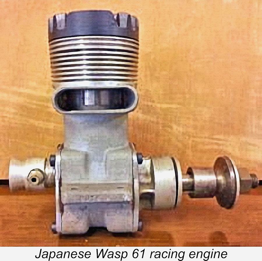 Many people are consequently unfamiliar with the Super Hope 60, assuming that it must have been just another McCoy 60 clone like the Japanese Super Devil and Wasp models, the English
 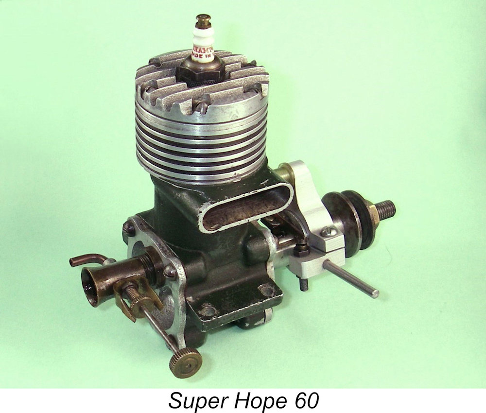 It must be admitted that the Japanese were talented copyists who could, and did, create exact replicas of Western products when they had a mind to do so - the pre-war Raku Shin is an exact copy of the Brown Junior, for example, albeit with a better timer than ever graced a standard Brown. It's also true that the Hope engineers must have been well aware of the general direction that competition engine design in the West had taken from the late 1930's onwards, either by seeing the engines in the metal or having access to accurate published descriptions.
 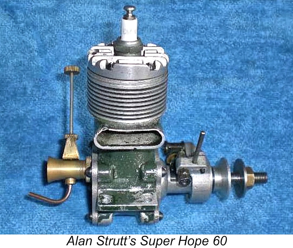 When this article was first published in September 2009, I didn’t have my own example of the Super Hope 60. The sole example to which I had any kind of access was an engine owned by Alan Strutt of England. Alan was kind enough to provide a quite detailed description of this engine, along with some images. This material formed the basis for that original article.
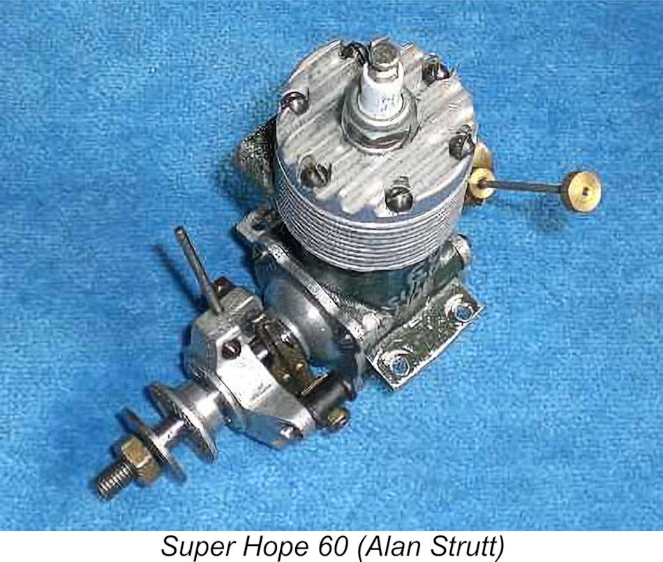 Beginning with the tale of the tape, Alan’s example of the Super Hope 60 had bore and stroke dimensions of 23.5 mm and 22.4 mm respectively for a displacement of 9.72 cc (0.59 cuin), slightly below the class limit. The engine weighed 379 gm (13.37 oz.) with plug and timer, thus being relatively light for a 10 cc racing motor of its day.
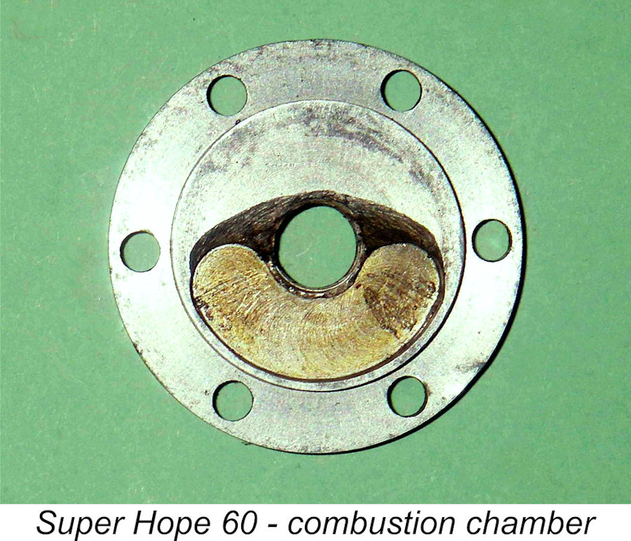 screws during the 1950's. The screws typify the basic Japanese engineering ethic of their time - just enough was quite enough!
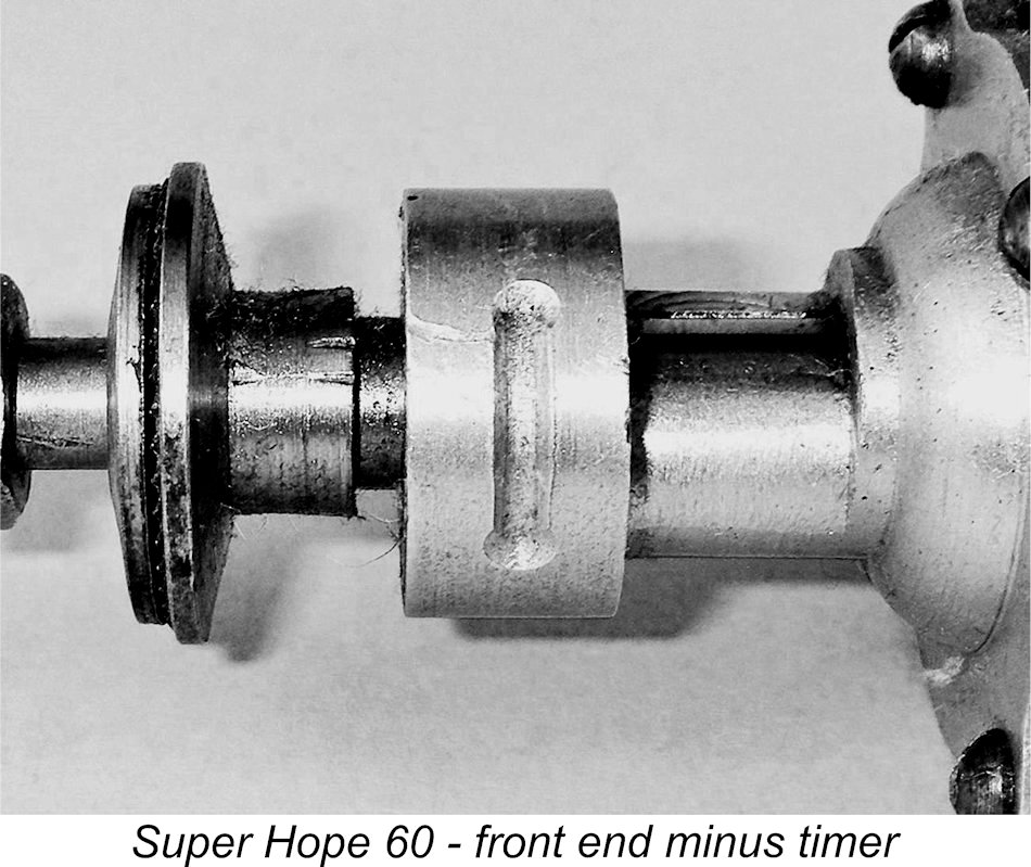 journal and the propeller shaft. A steel prop washer was used in conjunction with a brass prop-nut – another typically Japanese combination.
 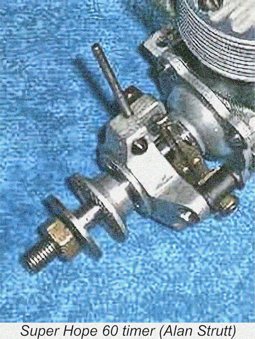 The timer assembly used on the spark ignition variant was of the open automotive type typical of racing engines of the period, featuring a strong leaf spring to control the moving point. It was mounted on a sand-cast alloy body that clamped around the machined outside diameter of the front bearing housing. Rotary movement of the timer (when unclamped) was limited by the previously-mentioned grub screw threaded into it. Timing adjustments were made by rotating the timer body using a short steel rod screwed into the body for purchase. The follower of the moving point was arranged to ride on the cam ground onto the crankshaft as it appeared in the gap between the two crankshaft bearing housings. All the screws found here were of the round headed variety described earlier.
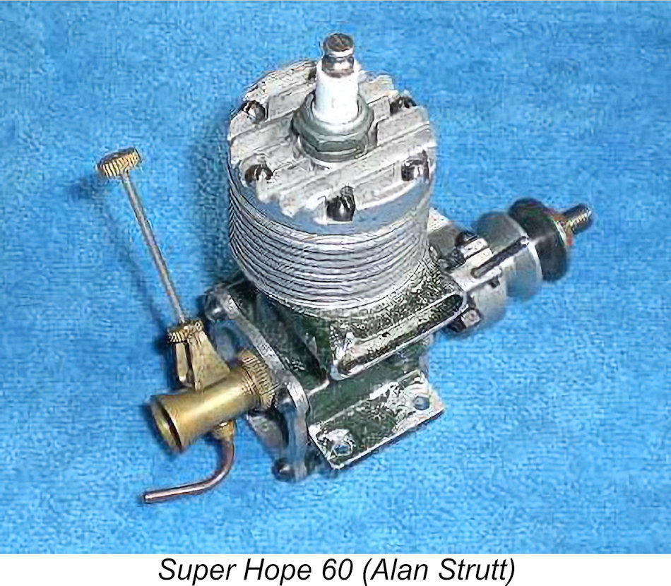 The rear housing was another sand-casting. The venturi assembly was threaded into a large appropriately-located tapped hole in this casting. The internal face of the rear housing was machined flat, with a 4 mm dia. hole being drilled through the centre of the casting along the engine's main axis. At the rear, this hole was sealed with a steel plug, leaving a blind internal hole which formed the bearing for the disc valve shaft. The round hole of the venturi drilling served as the inlet aperture, with no attempt being made to shape it to improve the induction dynamics.
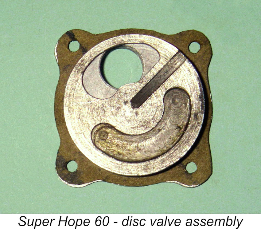 The steel disc itself was a massive 2.6 mm thick. It was driven by the previously-mentioned squared-off end of the crankpin, which engaged with a radial slot cut into the disc. The kidney-shaped induction hole formed in the disc left the circumference of the disc unbroken – identical to that used in the humble
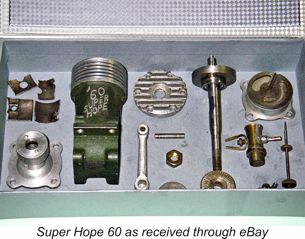
 Some of the shards of the broken piston were lost, but enough was left to allow me to obtain most of the major measurements. However, none of the crown was present, leaving me with no way of knowing the precise height of the crown nor the dimensions and location of the baffle. Thankfully, Alan Strutt was kind enough to dismantle his own example of the engine to measure the piston for me.
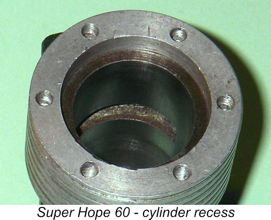 I took a lot of care with the fitting, the result being that the compression was now excellent, although the new piston could clearly use some running-in.
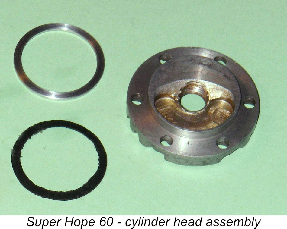 After having a good think about this, I made a 0.040 in. thick spacer ring of aluminium alloy. This was positioned on top of the cylinder flange, relying on a good metal-to-metal interface for a seal. I then placed a thin fibre gasket on top of the spacer ring, directly beneath the head. Between the two of them, the gasket and the spacer more than made up the space between the head spigot and the top of the cylinder.
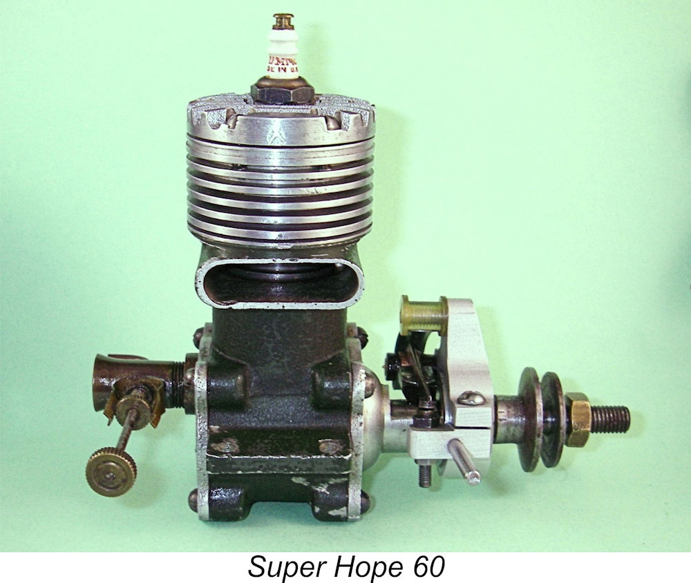 The logical inference is that this particular unit was custom-made for an American client, probably a member of the forces of occupation. This would explain both the American plug thread and the presence of the engine in the USA when acquired by me years later through eBay.
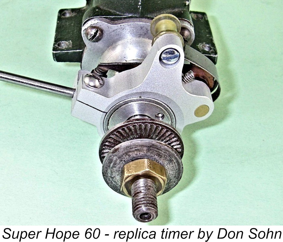 It seems that this example was nominally built right up to the full 10 cc limit. The slightly shorter stroke may have been intended to compensate for a marginally heavier piston resulting from the increased bore, or it may simply represent a measure to reduce vibration a fraction.
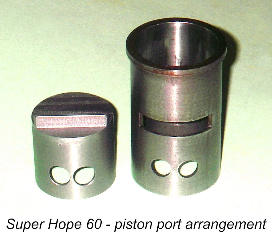 I was able to confirm the location and dimensions of the piston ports from the remains of the original piston. Interestingly enough, they were a little larger than the corresponding cylinder ports, also being very intelligently located a little further down the skirt than one might expect so that they were almost fully open when the transfer port was first opened by the piston. This means that they'd be fully open when they were most needed - to move fresh mixture from the crankcase into the bypass and thence into the cylinder while the transfer port was still opening and crankcase pressure remained high. By the time bottom dead centre was reached they were partially closed again, but at that point they would no longer be needed anyway since much of the crankcase pressure would have been dissipated.
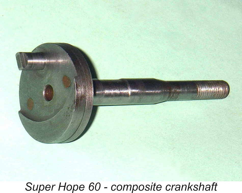 Looking at the lower end of the engine, an obvious departure from Alan's example described earlier was the use of a composite crankshaft in this example. The full-disc crankweb was radially split more or less in the middle, thus being made up of two discs set face to face in close contact with each other. The rear portion carried the crankpin and counterbalance, while the front portion was a simple disc machined integrally with the main crankshaft journal.
 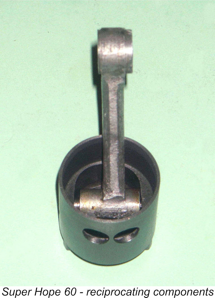 Now all of this represents a level of complexity for which there simply has to be a rational explanation. I've thought about this a lot, and the best explanation that I can come up with is that it must be related to a desire to improve the engine's balance factor. With that heavy 17 gm piston going up and down at a rate of knots, this must have represented a real issue for the designer and a potentially significant limitation upon the engine's ultimate performance.
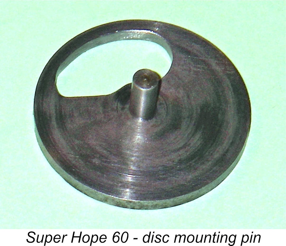
 All of this reinforces my view that this engine was probably never intended for series production in any commercial sense. Rather, it was a limited-edition "special", probably individually produced more as a manufacturer's statement than anything else with little or no consideration given to the issue of manufacturing cost. There's simply no way that this engine could have been manufactured at anything approaching a reasonable unit cost, even in late 1940's Japan.
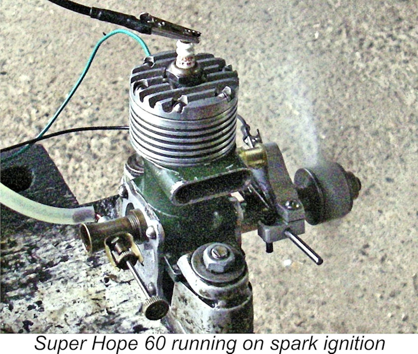 A subsequent test of the Super Hope 60 on spark ignition was equally successful. For these runs I used an APC 10½x6 airscrew with a white gas/mineral oil fuel mixture. The replica timer made by Don Sohn worked flawlessly, combining with the
 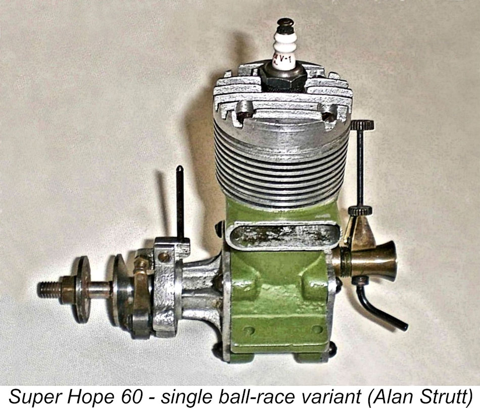 Turning now to Alan's later acquisition, this was another spark ignition model which exhibited a number of marked departures from the construction of the two examples described so far, thus presenting us with yet another variant of the Super Hope 60. Once again, this example came from an American source along with a report that it had apparently been intended for use in something described by the seller as a "Japanese SMITH tether racing car". The seller was unable to clarify what this meant - he was simply selling off items from an estate and only knew what he'd been told.
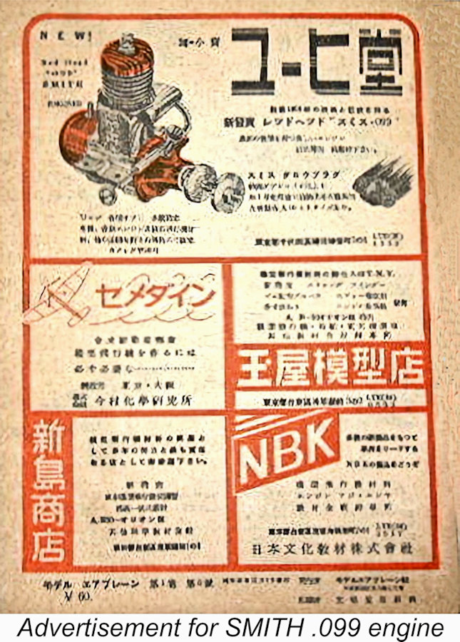 The application of the name SMITH to a range of Japanese-made modelling items seems improbable at first sight. However, there is considerable evidence to support its use in this context. To begin with, I’ve found an advertisement from a Japanese modelling publication of unknown date featuring a SMITH “Red Head” 099 model aero engine. Has any reader ever seen one of these engines?!? I haven't!
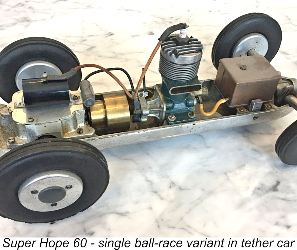
 The timer arrangements were somewhat different as well. The cam was not machined into the middle of the crankshaft journal as on previously-encountered spark ignition models, but was formed instead as an integral element of the steel prop driver. This had the benefit of eliminating the cutaway between the ball-race housings which was criticized earlier for weakening the front end of the engine.
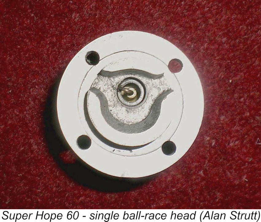
 The Super Hope 60 was clearly built in very small numbers more or less as a “custom order” item. This allowed the makers to put a higher than usual level of effort into the construction of each example, also facilitating the application of design modifications to the engine as time went by. The result was a very high quality engine which was under continual development.
| |