
|
|
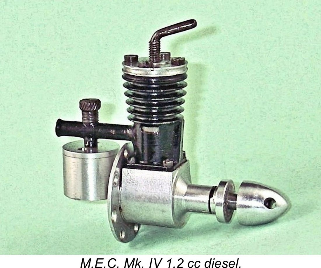
A Premier Powerplant - the M.E.C. 1.2 cc Mk. IV Diesel
However, my mate Ron left us in early 2014 without sharing the access codes for his heavily-encrypted site. Because no maintenance has since been possible, the MEN site is slowly but perceptibly deteriorating - an inevitable process which can have only one ending in the long run. I was unwilling to risk the loss of the information so painstakingly gathered on the M.E.C., hence the article’s re-publication here. Quite apart from the above consideration, a significant amount of new information has since come to light, particularly with respect to the Lionheart "dummy twin" unit which was briefly offered alongside the M.E.C. in 1949. My sincere thanks to Gordon Beeby of Australia for bringing this information to my attention. Gordon also contributed immensely to the ferreting out of additional advertising material relating to both the M.E.C and the Lionheart. Without this kind of help, I couldn't complete any of these articles with any claim to authority - thanks, mate! Much more about the Lionheart in a separate article to be found elsewhere on this website. The neat little ultra-lightweight M.E.C. 1.2 cc diesel which is the primary focus of the present article has hitherto been almost completely undocumented. All we have to go on are a few advertisements, a couple of brief media references and an actual example which is fortuitously available for evaluation. This being the case, I must make it clear at the outset that a significant proportion of what follows can legitimately be viewed as no more than informed speculation. Should further facts come to light in the future, I will of course amend this article as necessary, giving full credit to my sources. As always, research of this nature is quite impossible without the help of others. I already acknowledged the assistance received from Gordon Beeby. I also have to thank my good friend and valued colleague Kevin Richards not only for making available the fine example of the ultra-rare engine upon which this article is based but also for digging out much of the related advertising material. Without Kevin's help, I couldn’t have even begun this analysis, let alone completed it. Thanks, mate! OK, armed with the relatively sparse resources at our disposal, let's see how we get on. Background
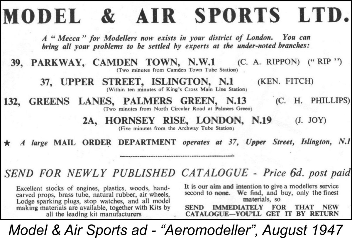
Accordingly, the name is correctly pronounced "em-ee-see" rather than "mec". Fair play - no-one refers to the E.D. range as the "ed engines"! The M.E.C. 1.2 cc Mk. IV diesel was produced in very small numbers in London, England over a period of approximately fourteen months beginning in March 1948. It appears to have been a small-scale artisan workshop production rather than a mass-produced item like most of its competition. In his very engaging 2014 book entitled "British Model Aero Engines 1946-2011", author Ted Sladden identifies the manufacturers as M.E.C. Precision Engineering of London but unfortunately provides no supporting evidence for this identification, nor does he cite an address. The little M.E.C. was mentioned in the 1949 second edition of Col. C. E. Bowden's book “Diesel Model Engines”, also being included in the technical tables published as appendices to Ron Warring's 1949 book “Miniature Aero Motors”. It appeared yet again in the May 1950 third installment of Col. Bowden's multi-part "Review of British Commercial Model Engines" which ran in "Newnes Practical Mechanics" magazine. This article includes the only recorded address for the M.E.C. company, giving it as 33 Cazenove Road, London, a little to the north-east of Islington and today a residential area. However, Bowden still doesn't tell us what M.E.C. stood for, although he does mention a number of other models which were then under development, including a tiny 0.25 cc diesel. However, these designs never materialized. Interestingly enough, Ron Warring did not include the M.E.C. 1.2 in his table of model diesel engines for 1948/1951 which was published in “Model Aircraft” magazine in June 1951. Presumably he felt that the engine had failed to make a sufficient mark to warrant inclusion! Warring's views in the above regard most likely stemmed from the fact that distribution of the little M.E.C. seems to have been restricted to a relatively small geographic area in North London, apparently being focused for the most Premier Aeromodel Supplies was one of Britain's pioneering model supply houses. The firm had been trading since 1929 from a location at 2A Hornsey Rise, a little to the north of Islington. The precise location was the north-west corner of the intersection of Hornsey Rise and Hazellville Road, as seen on the accompanying hand-drawn map from the company's 1939 catalogue. This location has been re-developed since WW2, now being incorporated into the area of Elthorne Park. Premier Aeromodel Supplies were both manufacturers and retailers - in The Premier company continued trading throughout WW2, as demonstrated by their periodic placement of advertisements during that unhappy period during which modelling activity was highly restricted. The conclusion of hostilities found them still very much in business at their pre-war address. Their main focus was the supply of kits and accessories of their own manufacture, but they also seem to have offered a wide range of modelling goods from other sources. At some point prior to July of 1947 Premier became a participant in what appears to have been some kind of a consortium of model shops at four North London locations. This consortium traded under the collective name of Model & Air Sports Ltd., with branches at 39 Parkway, Camden Town (managed by C. A. "Rip" Rippon of future Ripmax fame); 37 Upper Street, Islington; and 132 Greens Lanes, Palmers Green as well as the Premier Aeromodels address at 2A Hornsey Rise. It's a little odd to note the relatively close proximity of these locations to one another. Upper Street in Islington is no great distance from either Hornsey Rise or Parkway (Camden Town). Even Palmers Green is only a little to the north of Hornsey Rise, while the East End Road manufactory At first glance, such a concentration of similarly-focused retail outlets in a relatively small geographic area doesn't appear to make much sense for a single business entity. One actually gets a strong impression that this was a case of a group of originally-independent model shops in relatively close proximity to one another getting together to work co-operatively rather than in a state of mutual competition in which at least some of them must surely have gone under. The Upper Street address in Islington was apparently the central location of Model & Air Sports' mail order service. Membership in the consortium evidently did not require the participants to surrender their previous identities, since Premier Aeromodels continued to advertise under their own name throughout, sometimes placing their advertisements immediately adjacent to those of Model & Air Sports Ltd. However, in doing so they invariably used the East End Road address of their manufacturing facility in East Finchley - their retail outlet at 2A Hornsey Rise apparently operated under the Model & Air Sports Ltd. banner during this period. It appears that Premier were presenting themselves as kit manufacturers rather than retailers at the time. At this late date, it's no longer possible to sort out the respective roles of Model & Air Sports and Premier Aeromodels in the production and marketing of the M.E.C. diesel. All that can be said is that the engine was advertised by both entities during its short production life and that Premier Aeromodels appears to have been the most active and persistent individual member of the Model & Air Sports consortium in promoting the little M.E.C.
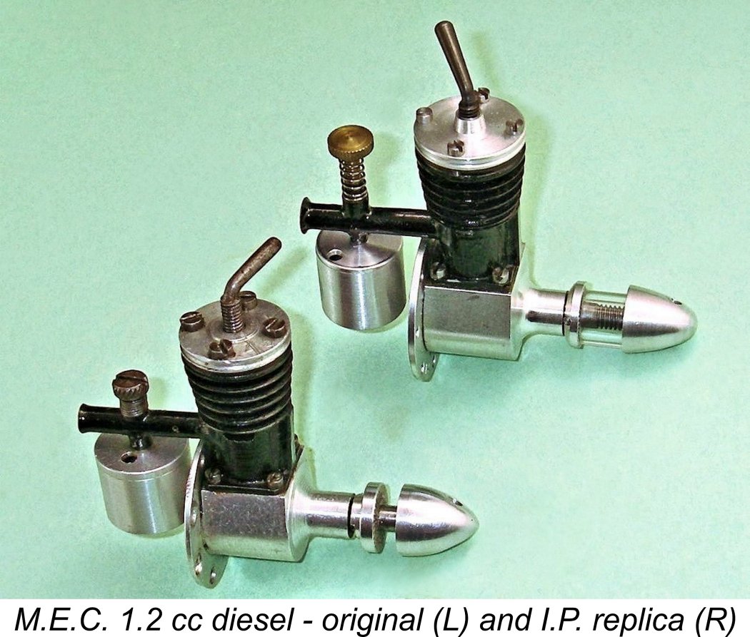
There is some support for this theory in the form of the engine's name - the M.E.C. designation bore no relationship to the names of the two business entities which marketed the engine. Moreover, almost from the beginning the engine was referred to as the M.E.C. 1.2 cc Mk. IV diesel. This clearly implies that by rights there should have been preceding Mk. I, Mk. II and Mk. III models, but I can find no firm evidence that such models were ever marketed, at least under those designations. Of course, this by no means proves that they never existed! It's perfectly consistent with the above theory to suppose that the unknown designer (whoever he was) had gone through three previous iterations of the design, perhaps selling them unadvertised to friends and associates, before finally settling on the fourth and final version as being worthy of small-scale series manufacture, subsequently approaching the local model trade to secure a marketing agreement which would expand the sales base for that variant. There is of course the alternative possibility that Premier Aeromodels or Model & Air Sports themselves conceived the notion of having the engine produced for them and approached the unknown maker to arrange for this to be done to their specifications. However, this is surely inconsistent with the fact that they did not apply either of their own proprietary names to the engine. Moreover, such a move into the engine manufacturing field would represent a major shift in focus from Premier's previous interests, which had generally been connected with the supply of kits, plans, materials and accessories. It's hard to see why such a relatively small retail company would choose to go head to head with the ever-increasing number of established engine manufacturers which were then supplying the needs of British modellers. Furthermore, the above possibility does not explain the apparent anomaly of the Mk. IV designation and the seeming absence from the market of the three implied earlier models. Overall, some form of external "persuasion" seems far more likely. It's highly doubtful that we'll ever know - all of the principals are surely long departed after the passage of over 75 years. Regardless, the fact that production of the engine appears to have been tailored towards its sale through a single North London retail consortium doubtless explains its extreme rarity today. With such a localized marketing history, it's only to be expected that very few of these engines would in fact have been completed and sold. The apparent present-day scarcity of surviving original examples backs this up - a mixture of As you do so, bear in mind that the M.E.C. actually experienced a brief revival in the 1990's when Ivan Prior's I.P. Engineering company of Milton Keynes, Buckinghamshire produced around 20 examples of a superbly-made replica of the original M.E.C. Mk. IV. You're probably far more likely to The I.P. replica of the M.E.C. is extremely faithful to the original. M.E.C. as well as being of the very highest quality. Fortunately, there's little chance of an Ivan Prior replica being passed off as a genuine original example of the engine. Ivan stamped the mounting ring of his replicas very clearly with the I.P. identification along with the three-digit serial number. The originals displayed no markings at all. Ivan also used a significantly longer needle valve on his replicas. It has not been possible to identify the designer and/or maker of the original M.E.C. 1.2 Mk. IV - in fact, we don't even know what the letters M.E.C. stand for! The periods suggest that they are initials - perhaps those of the designer..............or Model Engine Somethingorother? At this late stage, I have to accept the likelihood that this information has been irretrievably lost through the passage of time, but if by chance anyone out there knows more than I do, I'd be absolutely delighted to hear from you! My sole motivation in publishing these articles is to encourage the capture and preservation of as much model engine history as possible while the smallest crack remains open in the steadily-closing window of opportunity. All contributions openly and gratefully acknowledged! Production and Marketing History Thanks in large part to some excellent work by Kevin Richards and Gordon Beeby, I have access to a fair number of advertisements for the M.E.C. diesel. These allow me to trace the production history of the engine with some confidence.
The Model & Air Sports advertisement was an "introduction" of the M.E.C. engine, thus dating its initial appearance pretty closely to March 1948, allowing for Editorial lead time. Interestingly, the displacement of the engine was given as 1.1 cc rather than the 1.2 cc quoted later. The cited weight too was slightly different at 1.7 ounces. It's accordingly possible that this was one of the earlier "Marks" under which the engine's later Mk. IV title suggests that it was produced. In his previously-cited book, Ted Sladden included several images of what was claimed to be a 1.1 cc version of the M.E.C., although it looked identical to the 1.2 cc model. If this unsubstantiated claim is authentic, it may represent the Mk. III version of the engine.
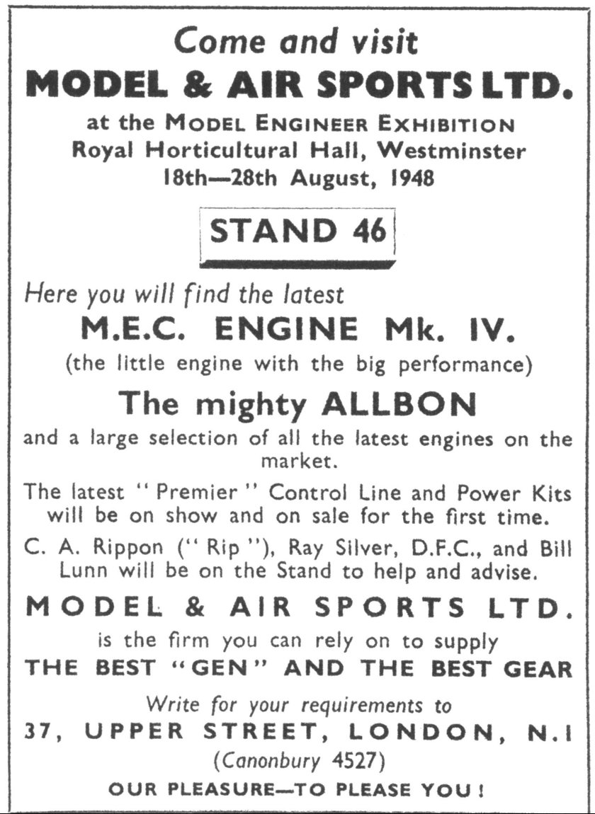
If the above advertisement was indeed for an earlier Mark of the engine, it didn't last long - by August of 1948 we find the attached advertisement in “Model Aircraft” (again placed by Model & Air Sports) specifically touting the "latest" Mk. IV version of the M.E.C. diesel. The use of the word "latest" certainly implies that there had been at least one earlier model - perhaps the 1.1 cc variant featured in the earlier advertisement and mentioned by Ted Sladden. Readers were invited to visit the Model & Air Sports stand at the August 1948 Model Engineer Exhibition, where both the Mk. IV version of the M.E.C. diesel, the "mighty Allbon" (presumably the 2.8 model) and the latest kits from Premier Aeromodels would be on display. C. A. "Rip" Rippon was among the "stars" scheduled to staff the exhibit, as was Premier's designer Ray Silver.
This advertisement provides some important additional information by specifically claiming that the engines were "individually built, not mass produced". This clearly implies an artisan workshop level of production in accordance with my earlier speculation. The engines were stated to be "produced entirely of first-grade bar materials", i.e., no castings were employed. An examination of the engine confirms this latter statement.
The basic information on the engine was also unchanged from that which had appeared in the October placement by Premier Aeromodel Supplies, although it did include the claim that the engine was "indisputably above all comers in the field for power (to weight?) ratio". Interestingly, inquiries were invited at only the Upper Street address - no mention of the Premier location! This may be a further sign that the consortium was in the process of disintegrating - the "partners" had begun advertising in competition with each other! Another seemingly obscure point about this advertisement was the note that the engine was "adaptable to inverted or upright running". Given the fact that the carburettor assembly was entirely soldered together (as we shall see) and was set up as supplied for upright running, it's difficult at first sight to see how this claim could be substantiated. However, read on .............all will become clear!
Premier's June 1949 placement in “Aeromodeller” made no mention of the M.E.C., but that model did reappear in their July 1949 “Aeromodeller” advertisement (left), although it was by then playing second fiddle to a number of other products which were more prominently featured. As far as I am aware, this was the final advertising appearance of the engine under the Premier banner. It actually appears likely that production had ceased by that time and they were merely selling off unsold examples. The above summary strongly implies that the M.E.C. was a small-scale artisan creation which was only in limited production for about a year and was sold within a very small geographic area. This being the case, one would expect production figures to be relatively low. These considerations certainly explain the relative scarcity of surviving examples today. Probably only a few hundred at most were made in total. The M.E.C. In Print
“The 1.2 cc M.E.C. is a very light motor weighing only 1-1/2 ounces. The makers claim it weighs one-third less than the lightest of its approximate cc and can be used on sailplanes without any other alteration than for fixing. The engine has a high power-weight ratio. It has even flown a lightly-loaded 7 ft. span model with success. Only M.E.C. fuel is supposed to be used with this motor. The bore is 0.450 in., stroke 0.460 in. Height 1-7/8 in., length 3-1/8 in., width 3/4 in., diameter of bulkhead fixing flange 1-1/4 in.” Unfortunately, Bowden did not supply details of the mysterious fuel - perhaps the makers were not forthcoming on this subject. It's interesting to note that the promoters were definitely touting the extremely light weight of the engine, which made it suitable for use in models which were originally designed as sailplanes or (presumably) for rubber power. Readers of my article on the Kemp (later K) Hawk will recall that the makers of that engine cited similar applications in their advertising. At this stage, small diesels were widely seen as replacements for rubber power or towlines rather than as powerplants on their own merits. The M.E.C. was also included in the technical tables which appeared as appendices in Ron Warring's 1949 book “Miniature Aero Motors”. However, those tables are confined to technical data only, hence adding nothing to our knowledge of the engine's antecedents as summarized above - they merely confirm my direct observations (and vice versa!). There was no reference to the engine in Warring's text. For several decades thereafter, the modelling media remained silent on the subject of the M.E.C. diesel. Gordon Beeby found what appears to be the next media reference to the engine, which took the form of a few paragraphs in Peter Chinn's "Latest Engine News" column in the February 1970 issue of "Aeromodeller". Chinn had been asked to identify an example sent in by a reader, and was able to do so. He included a brief description of the engine without naming the maker, whose identity was presumably unknown to him. This rather brief reference therefore adds nothing to our knowledge of the engine. Apart from a one-line mention on page 41 of O. F. W. Fisher's 1977 book “Collector's Guide to Model Aero Engines” plus a cameo appearance on page 120 of Mike Clanford's useful but often unreliable 1987 book “A-Z of Model Engines”, the references cited above appear to constitute the sum total of the M.E.C. 1.2 cc diesel's appearances in the modelling media prior to the original appearance of the present article on MEN in 2010. As previously cited, the engine was subsequently included in Ted Sladden's 2014 book, but once again that inclusion didn't advance our knowledge of the engine all that much. Having reviewed the above rather scanty background material, let's now take full advantage of the fact that I have a fine example of this engine available for direct examination. Description
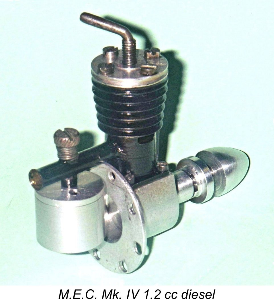
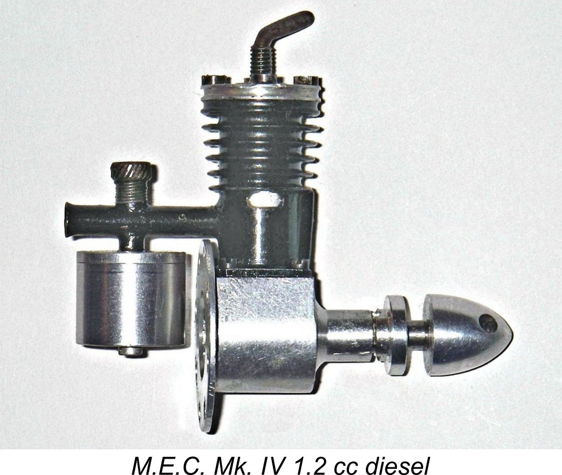
Ted Sladden included several fine images by Kim Watson of an engine purporting to be a 1.1 cc model, although that claim unfortunately cannot be substantiated by direct measurement. The only apparent difference between the illustrated claimed 1.1 cc unit and the confirmed 1.2 cc model is the use of a wrap-around carrier for the tank/needle valve assembly. The M.E.C. 1.2 cc Mk. IV diesel which was first announced by that name in August of 1948 was a basically conventional side-port diesel of its day, mainly distinguished by its remarkably compact dimensions and light weight for its displacement as well as the fact that it was arranged exclusively for radial mounting. This form of mounting was actually enjoying something of a One's initial impression upon first encountering the M.E.C. is that there's no way that it could possibly pack 1.2 cc into its compact ultra-light structure! By comparison with models of similar displacement from other makers, the engine looks positively minute! However, a careful check of the illustrated example confirms the cited displacement figure exactly. The makers claimed a weight of only 1.5 ounces for the engine. This weight is more or less correct if one removes the hang tank supplied with the unit. However, with the tank in place, my illustrated example weighs in at 55 gm (1.94 ounces) all complete. This is still well below the weights of any of its direct competitors, including several Unusually at a time when long-stroke designs still predominated in Britain, the M.E.C. featured almost "square" internal geometry. Bore and stroke were 0.450 in. (11.43 mm) and 0.460 in. (11.68 mm) respectively for a calculated displacement of almost exactly 1.20 cc (0.073 cuin.) as claimed. The illustrated example checks out at almost exactly these figures, the very small departures being consistent with normal production tolerances. To modern eyes, the 1.2 cc displacement seems a little offside. However, engines having what we would consider today to be "orphan" displacements such as this were by no means uncommon in the late 1940's and even into the 1950's. At the time of which we are speaking, the issue of displacements for competition classes was far from standardized - for example, the "magic" displacement of 2.5 cc (0.15 cuin.) was still over 5 years away from being adopted by the FAI for international competition. Quite apart from this, aeromodelling was still far more a widely-practised hobby than a sport in those far-off days. Consequently, the vast majority of modellers were not as interested in all-out competition as they were in simply enjoying their aeromodelling activities and gaining experience using dependable equipment. In such a context, no particular displacement really had much of an edge over another. The only issues were what size of model was desired and whether or not a given engine could do the job of flying that model to the standard required while giving the operator a minimum of trouble in doing so.
Seen in this 1948 context, there was actually nothing at all extraordinary about Model & Air Sports or Premier Aeromodel Supplies marketing what was presumably intended to be their "exclusive" in-store model with a displacement of 1.2 cc. In all probability the designer(s) simply established the physical design parameters in terms of target weight and physical size and then pushed the displacement up to the limit allowed by those parameters, thus maximizing the potential power/weight ratio. Indeed, it appears that the major design objective with this engine was to maximize that ratio.
However, the Mills benefited from being the only one of these models to enjoy a truly national distribution network backed by an adequate production capacity. As a result, in sales terms it was no contest - the Mills almost certainly outsold all of the rest put together over the same period! Certainly, it was the only one of them to survive. In terms of its physical construction, a present-day inspection of the M.E.C. 1.2 cc diesel reveals that the basic structure is very simple indeed. As advertised, no castings are used at any point, the entire engine being machined from bar stock. The crankcase is machined all over and has clearly been hogged out from the solid rather than cast. The main bearing is formed integrally with the crankcase, being fitted with a pressed-in steel bushing. The backplate is a conventional screw-in item which incorporates a large-diameter flange at its outer edge. A ring of holes having a 1 in. pitch circle diameter is drilled in this flange to provide for radial mounting of the engine. It is of course essential that this component be really well tightened prior to use, since starting torque arising from the necessary flick-over tends to unscrew the engine from the backplate. Once running in the conventional direction, however, the engine's torque reaction will tend to tighten the backplate. I chose not to disturb the backplate on my example since it was clearly mated to the crankcase very securely. No sense breaking a well-established seal!
Since the cylinder base has no locating spigot, it is laterally located solely by the four screws through the corners of the mounting flange - a somewhat questionable arrangement in my view, although the screws are closely fitted to their holes and the threads in the case are well formed. A thin fibre gasket is used to ensure a seal. A turned aluminium alloy cylinder head is secured to the top of the cylinder with four more screws. The head accommodates an L-shaped steel compression screw. Cylinder porting is more or less conventional for a late 1940's side-port diesel. Both the induction and transfer ports are simple round holes of reasonably generous size, while the exhaust chores are handled by two oval ports of quite adequate dimensions, one on each side. Unusually for an engine of this layout, the single circular transfer port overlaps the exhaust almost (but not quite) completely. It is fed through a bypass passage formed by brazing a narrow brass channel to the exterior of the cylinder A steel connecting rod of generous proportions is used in conjunction with a steel piston and one-piece steel crankshaft. The rod appears to have been hand-filed from a piece of flat steel plate. Bearing fits at both ends are excellent. This "all-steel" construction was a fashionable specification among British designers of the period, but it did not stand the test of time - the undesirability of the "hard-on-hard" approach in terms of wear was soon appreciated and progressively abandoned. The fact that the induction and transfer ports are round holes which are located fore and aft in the cylinder means that the 0.100 in. dia. gudgeon pin has to be restrained from movement in the piston bosses to avoid fouling the ports. This appears to have been accomplished by swaging the ends of the pin following installation - the associated punch marks in the gudgeon pin centres are very obvious. I made no attempt to compromise the fit by removing the pin. The one-piece steel crankshaft has an unbalanced plain disc crankweb. It has two flats machined into it immediately forward of the 0.220 in. dia. main bearing journal. The knurled aluminium alloy prop driver engages very snugly with these flats by means of a milled channel at the rear, very much along the lines of the contemporary Ace 0.5 cc unit. The prop mounting arrangements are completed by the addition of a neat aluminium alloy spinner nut.
The brass intake tube is soldered or brazed to the rear of the cylinder. A very thick transverse spraybar is soldered into this intake tube. This spraybar is drilled through along the intake alignment at slightly less than intake I/D, thus creating a constriction at the fuel jet location. I previously mentioned the manufacturer's claim that the engine was "adaptable to inverted or upright running". Given the fact that the carburettor assembly was entirely soldered together and was set up as supplied for upright running, the way in which this flexibility was provided is not obvious. However, in reality it's quite simple! The spraybar is axially drilled and tapped 8BA all the way through. The externally-threaded needle engages with this thread, being tensioned by a coil spring. On the opposite (fuel supply) side, an externally-threaded fuel jet of considerable length screws into the spraybar until the inner end is more or less flush with the wall of the induction venturi. It thus acts as a surface jet within the constriction created by the transverse hole in the spraybar. A significant length of thread is left exposed below the spraybar. The very neat turned aluminium alloy tank top is centrally threaded 8BA. It screws onto the protruding portion of the externally-threaded fuel jet, serving as a lock-nut to maintain the positioning of the jet, which is thus made adjustable. The brass fuel pickup tube is also internally threaded 8BA. It screws onto the residual protruding portion of the jet beneath the tank top, thus serving as a lock-nut to stabilize the tank orientation. Finally, the turned aluminium tank bowl itself is secured by an 8BA screw which engages with the lower end of the internally Hopefully this description coupled with an examination of the above fuel system component image will have clarified the construction of the M.E.C.'s fuel supply system. It should be clear that the tank assembly can be installed on either top or bottom of the induction tube, with the needle threading in from the opposite side. This confirms the promoters' claim that the engine can indeed be set up for either upright or inverted running despite the fact that the induction tube is soldered in place. It has to be said at this point that the engine is not ideally set up for radial mounting, especially if the standard hang tank is to be used in an upright mounting configuration. As can be seen very clearly in the image at the left, the front of the tank is very close to the rear face of the mounting ring, so one would either have to use a very thin mounting firewall or provide a fairly large cutaway in the firewall to create sufficient clearance for the tank. If it is desired to use the engine with a tank other than that supplied, all that is required is to remove the tank bowl retaining screw, discard the entire tank assembly and connect the engine to a separate tank using fuel tubing attached to the protruding end of the fuel jet. An odd feature which should be mentioned at this point is the presence of a tiny pin-hole in the right-hand side of the intake tube on the engine side of the needle valve assembly. This may be seen by close inspection of the above view of the engine. Its effect is to induce a small air bleed when the open end of the intake is closed for choking. Perhaps it was intended to minimize the possibility of over-choking and flooding. As we'll see, it doesn't appear to affect running. The previously-mentioned I.P. replicas do not incorporate this feature - evidently another sure-fire means of distinguishing between a replica and an original. The finishing touch is the application of a seemingly durable black engine enamel finish to the cylinder and intake tube. The result is a remarkably lightweight and compact little power unit which looks well able to give good service. All fits are well up to the very best standards throughout. The M.E.C. was never the subject of a published test, but something can be done about that! Flex that flicking finger, and on to the test bench! The M.E.C. On Test
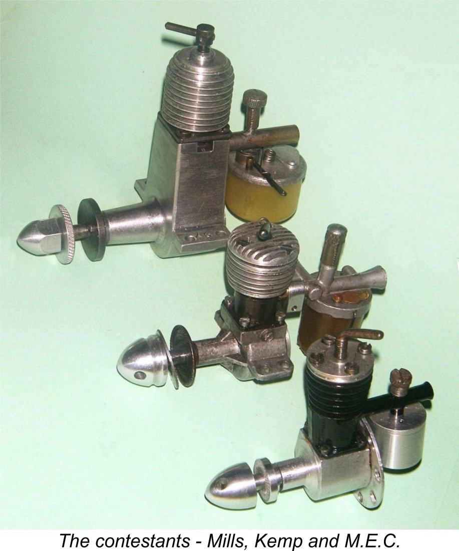
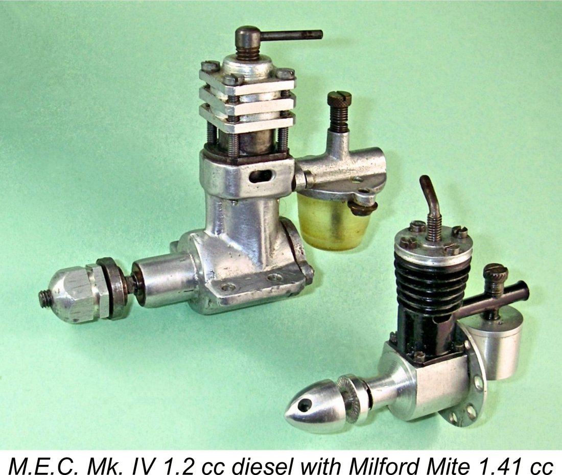
For comparative purposes, I could do no better than evaluate the M.E.C. against the design which must surely have been the contemporary standard of comparison - the somewhat larger, more expensive and far heavier Mills 1.3 Mk. I Series II. This iconic engine was in production up to May of 1948, thus being contemporary with the M.E.C. at the time when the latter unit first appeared. For the sake of interest, I also included the contemporary Kemp Eagle Mk. I side-port model, since that engine too was marketed for the most part in the London area at a comparable price, hence representing credible competition to the M.E.C. despite its slight displacement disadvantage. All three models are side-port designs, so the playing field appeared to be about as level as I could make it. The recommended airscrews for the M.E.C. as recorded by Ron Warring were a 9x4 for free flight and an 8x6 for control line. It was thus clear that these sizes would have to be included in the tests. I had earlier figures for both the Mills and the contemporary Milford Mite Mk. III using these and other airscrews, but for the sake of maintaining a direct comparison I repeated the tests with the Mills alongside those of the other two engines using the same props and the same fuel on the same day. The Mills actually improved slightly upon its earlier performance, highlighting the necessity of repeating the tests. The first task was to make up a radial mounting for the M.E.C. along with a suitable 2BA sleeve nut to allow for testing the anticipated prop sizes. These tasks accomplished, the testing could begin. The fact that all three tested engines have integral fuel tanks really did make testing very convenient - I have to echo Lawrence Sparey's often-repeated comment in that regard! For the tests, I used a quite "oily" mineral-based fuel with 2% nitrate equivalent. This level of nitrate is undoubtedly unnecessary for these low-speed engines, but it does reduce the compression requirements somewhat and may help to minimize stresses in the 75-year old components. That said, I’ve since learned that many old side-port diesels actually perform better on an un-nitrated fuel, although I didn’t fully appreciate that fact when I ran these tests back in 2010.
It turned out that a light prime was pretty much essential for starting - for some reason, choking alone didn't seem to do the trick. Perhaps it's that little air-bleed hole in the intake. However, once primed the engine invariably started in one or two flicks. Really user-friendly! For restarts, the compression could be left alone at its running setting, but the engine picked up better if the needle was pulled out half a turn. Again, that air-bleed hole was the likely cause of this behaviour. Once the engine was running, the needle could be closed down immediately half a turn to its running setting. This proved to be around 3½ turns from fully closed.
This example didn't appear to have had much use - in fact, it was still quite tight. The steel piston had a tendency to tighten very slightly in the bore when the engine was hot, causing the engine to sag - a not uncommon characteristic of engines having steel pistons running in steel bores. I think that an hour or so of running would be necessary to cure this. In addition, operation using an un-nitrated fuel would probably do much to minimize this issue. I should try again sometime using such a fuel..............
Even so, they aren't that bad! The M.E.C. turned the 9x4 Top Flite wood prop at 6,800 rpm. The Mills could only manage 6,600 RPM on this prop, while the Kemp was an also-ran at 6,200 RPM. The M.E.C. spun a Taipan 9x4 at 6,500 RPM, a little ahead of the 6,400 RPM managed by the Mills on the same day and well up on the 5,800 RPM of the Kemp Eagle using the same prop. I then tried an APC 9x4, which is a somewhat faster prop than the Taipan, finding that the M.E.C. got this up to 6,900 RPM against the 6,700 RPM of the Mills and the 6,300 RPM of the Kemp. There's no way of knowing the specification of the 9 inch prop that the engine was claimed by the makers to turn at 7,000 RPM, but on the basis of this test the claim seems entirely credible. I then tried the 8x6 Taipan prop, which the M.E.C swung at 6,400 RPM, again faster than the Mills at 6,200 RPM and the Kemp at 5,700 RPM. On the basis of these figures, it's obvious that using the recommended airscrews the M.E.C. was the clear winner in this particular contest! The following table summarizes the comparative rpm data.
The very roughly implied power output of the M.E.C. on the basis of this admittedly incomplete test appears to be at least of the order of 0.062 BHP at around 7,000 rpm. Nothing to get that excited about, but pretty good going in 1948 for an engine weighing less than 2 ounces! The unknown designer had reason to feel pretty pleased with himself!
And then there was the ubiquitous 1 cc E.D. Bee which also appeared in mid 1948. The Bee undersold the lot of them at £2 5s 0d (£2.25) at the time. Just for fun, I tried a 1948-vintage Mk. I Series I Bee on the same props, finding that it got the 9x4 Taipan up to a smooth and effortless 7,200 rpm without breaking a sweat! The other props were turned at similarly faster speeds. It's really hard to see how the M.E.C. could have competed with these second-generation designs which looked to the future rather than to the past. This in no way detracts from the fact that the M.E.C. proved on test to be a really delightful little engine to handle. Moreover, there's no denying that when it came to power-to-weight ratio it could give any of its competitors a run for their money! In making that claim, the promoters of the engine were being completely truthful. Aftermath - the Premier Lionheart 2.5 cc Faux Twin
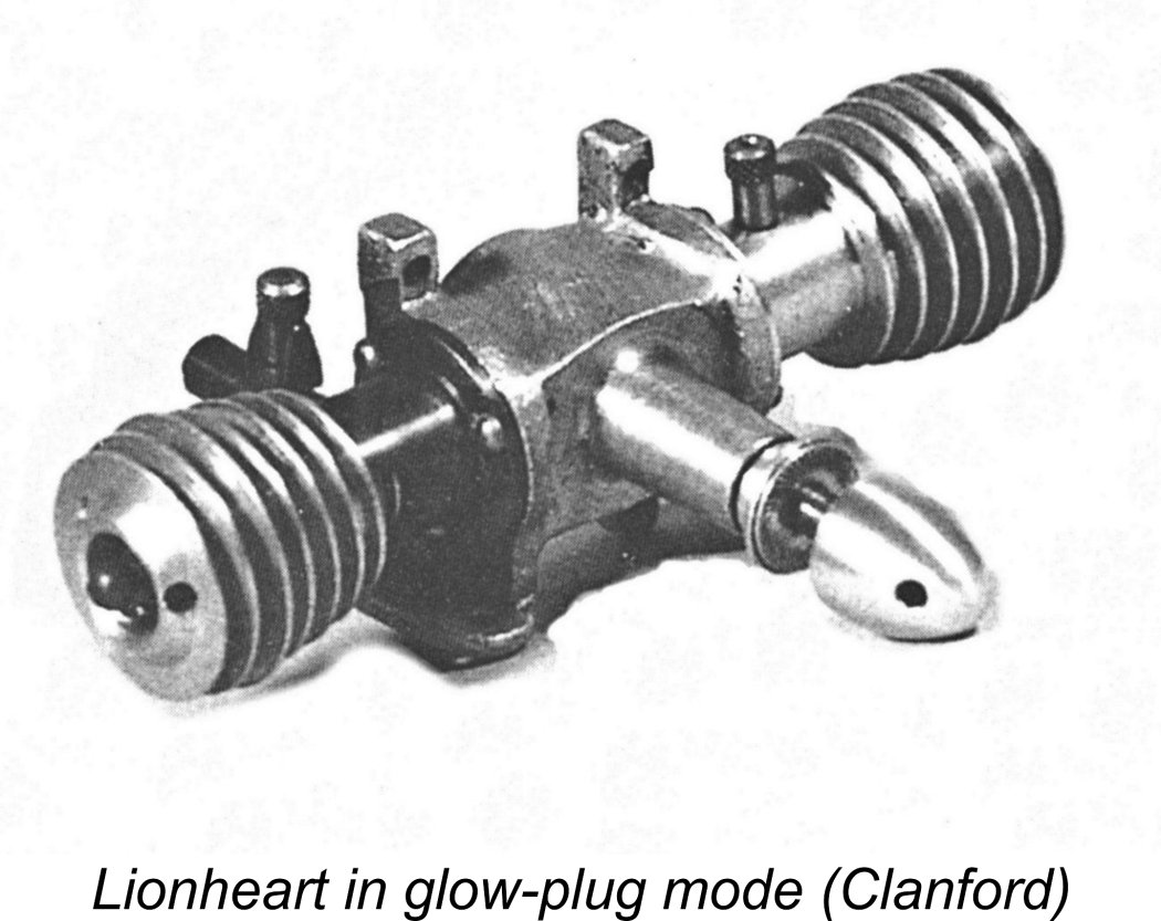
Sparey went on to present details and images of a completed 10 cc spark ignition prototype in the magazine’s July 1945 issue, as reproduced at the right. The Patent was actually granted on March 22nd, 1946, the Patent number being 576,207. My sincere thanks to Gordon for bringing these details to my attention. It appears that Sparey had moved quite rapidly to arrange for limited production of his brainchild following the granting of his Patent, since Premier Aeromodel Supplies Ltd. published an announcement in their “Aeromodeller” advertisement of September 1946 (reproduced below) stating that they would “shortly have available” a model diesel engine of “unusually robust design and layout which is the subject of a new British Patent No. 576,207”. This is none other than the Patent granted to Sparey on March 22nd, 1946! The advertisement stated that the proposed model would “be available in small It’s clear that unforeseen circumstances delayed the appearance of this engine, since it doesn’t seem to have put in a rather belated appearance until late 1948. In the interim, the company’s attention had become diverted to the M.E.C. 1.2 cc model discussed earlier. The engine that finally appeared as the Premier Lionheart looked for all the world like an opposed-twin design. In reality, it was a single-cylinder unit - the second opposed "cylinder" was a dummy which actually served as the fuel tank in accordance with the Sparey patent. Presumably the engine's appearance caused some confusion, because the manufacturers were at some pains to clarify the engine's true single-cylinder character in their later advertising. The single working cylinder was supplied with fuel through a conventional side-port induction arrangement. The Lionheart was produced in two distinctive variants having different cylinder porting arrangements. The manner in which the "instant conversion" from diesel to glow-plug ignition was very ingenious! In fact, the engine exhibits a sufficient number of quite distinctive features that it fully merits a separate article to itself, which appears elsewhere on this website. In the present article I'll stick to generalities. According both to the promoters and to the tables in Ron Warring's previously-referenced 1949 book, the Lionheart had a bore and stroke of 0.580 in. (14.73 mm) and 0.595 in. (15.11 mm) respectively, giving a bore/stroke ratio very similar to that of the M.E.C. However, these figures yield a calculated displacement of 2.57 cc (0.157 cuin.) which is at odds with the figure of 2.48 cc (0.15 cu. in) quoted by both Premier and Warring. This figure cannot be reconciled with the cited bore and stroke dimensions. A careful check of my own example yielded bore and stroke dimensions of 0.575 in. (14.605 mm) and 0.580 in. (14.732 mm) respectively for a displacement of 2.468 cc. I’m convinced that these are the correct figures and that there was a mix-up during the transmission of data and the preparation of the lay-out for the advertisement. Warring appears to have simply copied the advertising dimensions without checking them for consistency.
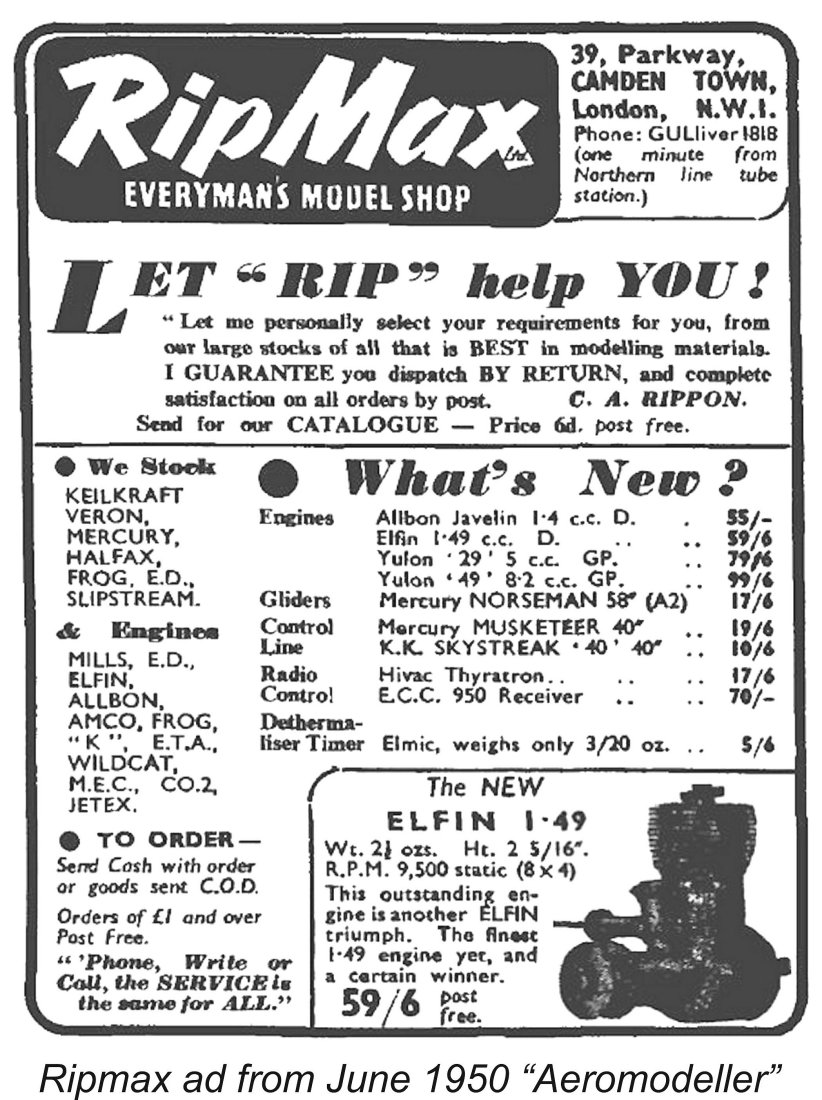
The express intended use of the Lionheart was to power scale models, then very much in vogue. The recommended airscrew was a 10x6 - there was no specific recommendation for control line or free flight use, although the advertising did claim that the engine incorporated a "perfect set-up for Control Line running". Claimed speed with the 10x6 prop was 5,500 RPM, while the engine was said to be good for maximum speeds in the 6,000-7,000 RPM range. The engine could be either beam or radially mounted. The Lionheart sold for the not-unreasonable price of £4 10s 0d (£4.50). It appears to have sold in even smaller numbers than its conventional 1.2 cc predecessor. Consequently, examples are in extremely short supply today. Unlike the M.E.C., the Lionheart engines evidently bore serial numbers - the number of the example that I was fortunate enough to acquire is 523. Since there's no way that anything like that many examples were manufactured, the significance of this number is obscure. Perhaps the series started at 500?!? Other serial numbers which have come to my attention seem consistent with this view. As with the M.E.C., the identity of the Lionheart’s manufacturer can no longer be determined. It's consequently unclear The level of Lawrence Sparey’s direct involvement (if any) in the manufacture of the As far as I’m able to determine, the Lionheart represented the swan-song of Premier Aeromodel Supplies in the model engine business. In fact, the company itself was apparently experiencing difficulties as of late 1949, evidently ceasing trading at that point, at least under the former name. It appears likely that the competition from nearby Ripmax (their former partner in the Model & Air Sports consortium) was too much to overcome. The Hornsey Rise address likewise disappeared from the model scene and subsequently from the London address book when the area was re-developed. Ripmax evidently took over the assets of Premier Aeromodel Supplies, since they continued to advertise a steadily diminishing range of Premier kits well into 1950. It would appear that they also took over a presumably small stock of unsold examples of the M.E.C. diesel, since that engine was still listed in Ripmax's advertisements for May and June 1950. Those were the final advertising appearances of the little M.E.C. The Lionheart was never mentioned in Ripmax's advertising. Conclusion
The M.E.C. was a significantly better-made engine than the Mite, but it never seems to have overcome its dependence upon the restricted geographic sales area covered by the Model & Air Sports consortium, which confined it to the sidelines and eventually doomed it in commercial terms. A further factor was doubtless the retrograde nature of the engine's design, which undeniably looked very much to the past rather than to the future. Basically, the M.E.C. was out of date as soon as it was released. All of which is a pity, because this is a really nice little engine which deserves to be better remembered than it has been hitherto. Its short-lived Lionheart companion also commands our respectful remembrance, particularly on the basis of its origins. I hope that this article will help to redress the balance in that regard! ________________________________ Article © Adrian C. Duncan, Coquitlam, British Columbia, Canada First published on MEN August 2010 This revised edition published here January 2023
|
|||
 Here we’ll share an in-depth evaluation of one of the more obscure model diesel engines to be produced in Britain during the early post-war era - the M.E.C. 1.2 cc diesel from North London. My
 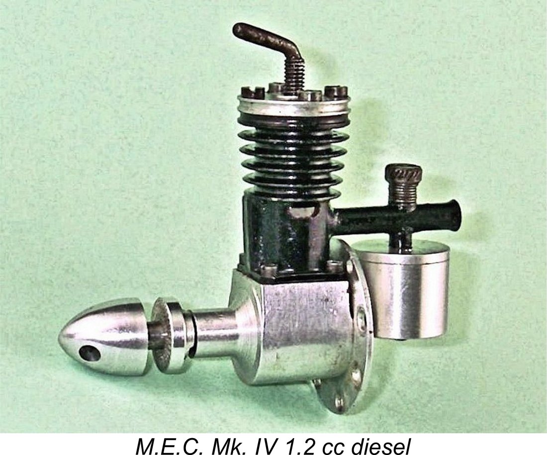 One point that requires clarification right up front is the issue of the engine’s name. It has variously been referred to as the MEC 1.2 cc diesel (no periods separating the letters) and the M.E.C. 1.2 cc diesel (with periods). I believe it to be a logical principle to follow the lead of the engine’s original promoters. Every advertising reference to the engine that I’ve ever seen refers to it as the M.E.C. 1.2 cc diesel. I’ve chosen to adhere to that identification throughout this article.
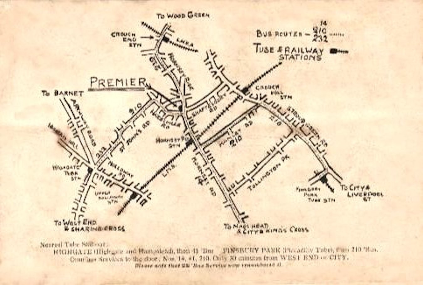
 rocking horse droppings and hen's teeth comes to mind! The near-mint example that I'm lucky enough to have on hand for evaluation is the only example that I've ever seen in the metal, while my good mate Kevin Richards (from whom I obtained the engine) has only seen two examples (including this one) in over 50 years of collecting! But there must be a few more of them out there; keep looking!
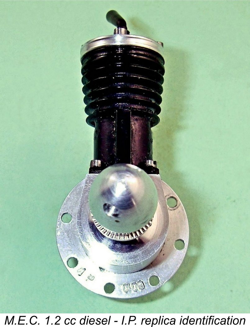
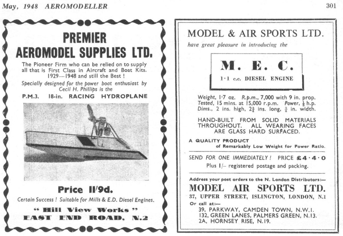
 The advertisement claimed that the engine had somehow survived a 15 minute test at 15,000 RPM (presumably using a flywheel) and would sustain 7,000 RPM with a 9 inch prop, likely a 9x4 if later recommendations are anything to go by. What the promoters though the 15,000 RPM stunt proved is quite beyond me! The quoted price was £4 4s 0d (£4.20). Mail order sales were invited, or one could call at any of the consortium's four listed retail locations.
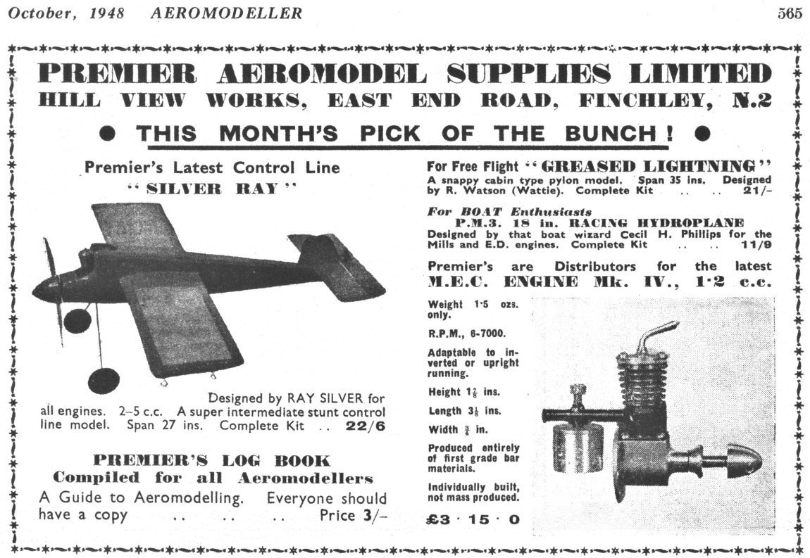
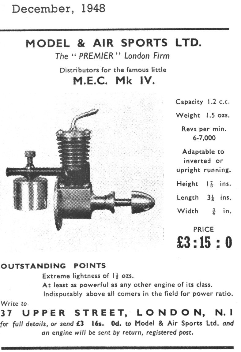 Model & Air Sports were back in the saddle in December 1948, still tipping their hats to their Premier Aeromodel partners by referring to themselves as the "Premier" London firm. Their advertisement which appeared in that month's issue of “Model Aircraft” focused entirely upon the M.E.C. Mk. IV (right). The engine continued to be offered at an unchanged price of £3 15s 0d. (£3.75).
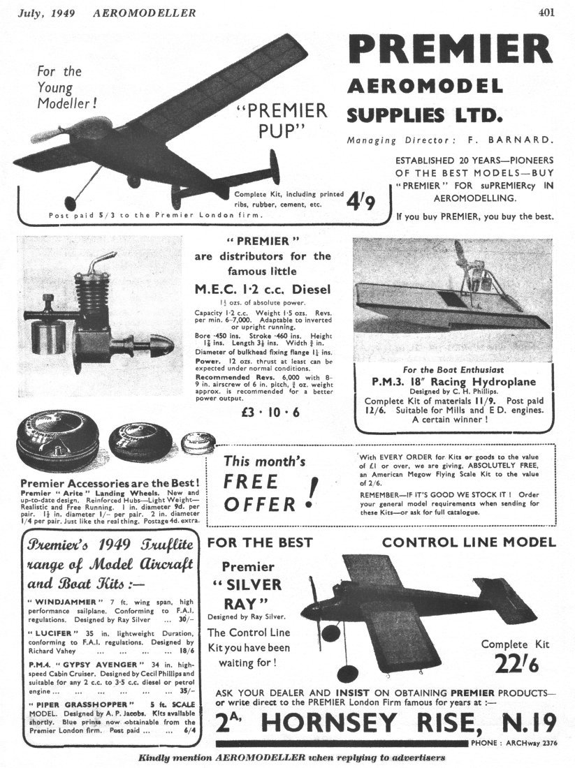
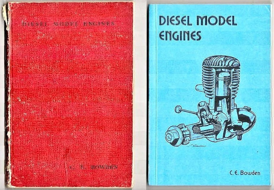 We saw earlier that the M.E.C. was mentioned in the 1949 second edition of Col. Bowden's book “Diesel Model Engines”. Since this brief summary appears to constitute the only description of the engine ever to appear in the contemporary modelling media, it seems worth quoting in full:
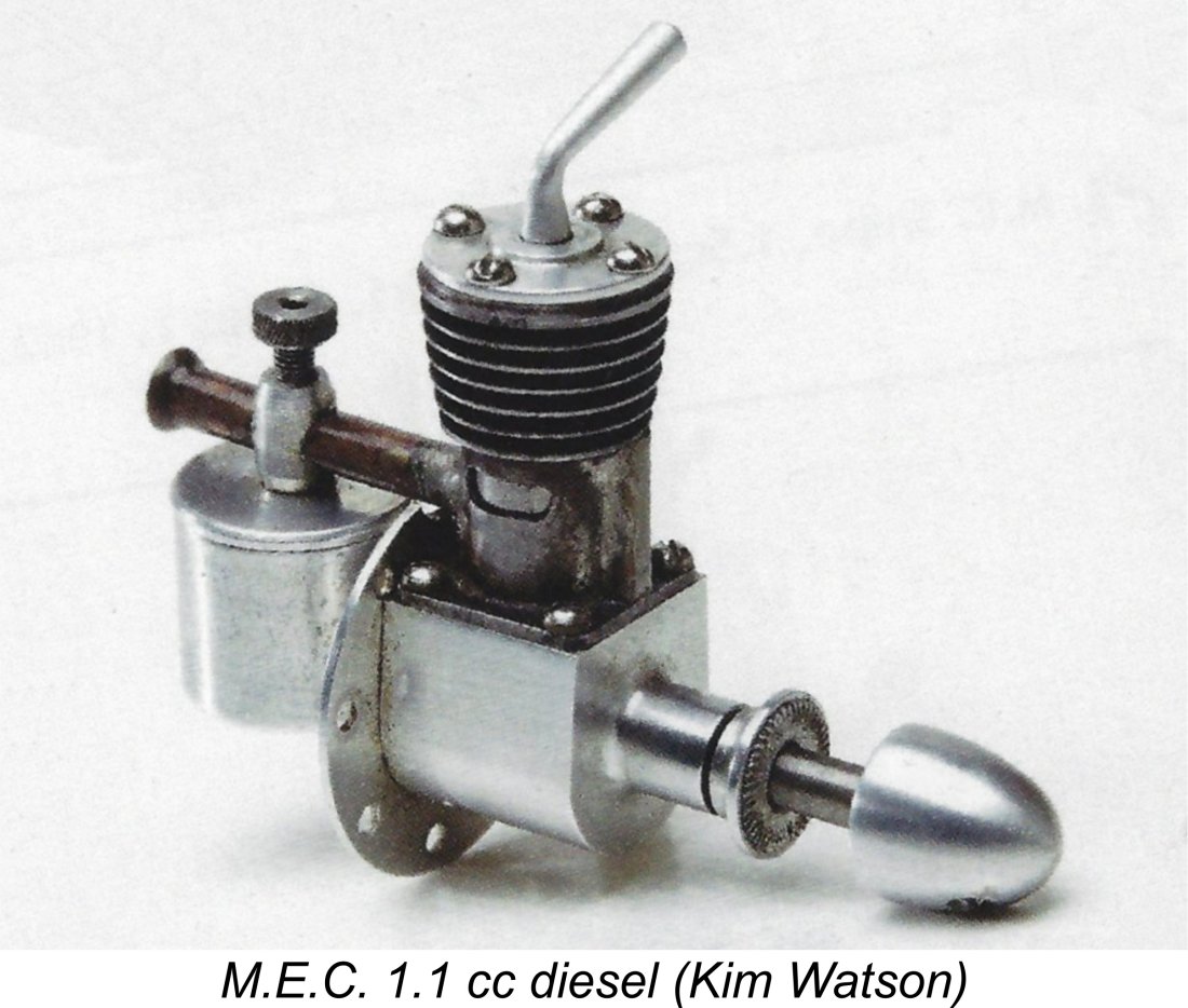 I have no authoritative information whatsoever regarding the initial form in which the M.E.C. was offered for sale. I noted earlier that the introductory advertisement of May 1948 referred to a displacement of only 1.1 cc along with a weight of 1.7 ounces. Both of these figures are slightly at variance with those subsequently quoted (and checked) for the Mk. IV version which forms my main subject. I can only assume that the original model was an earlier variant, perhaps the Mk. III.
 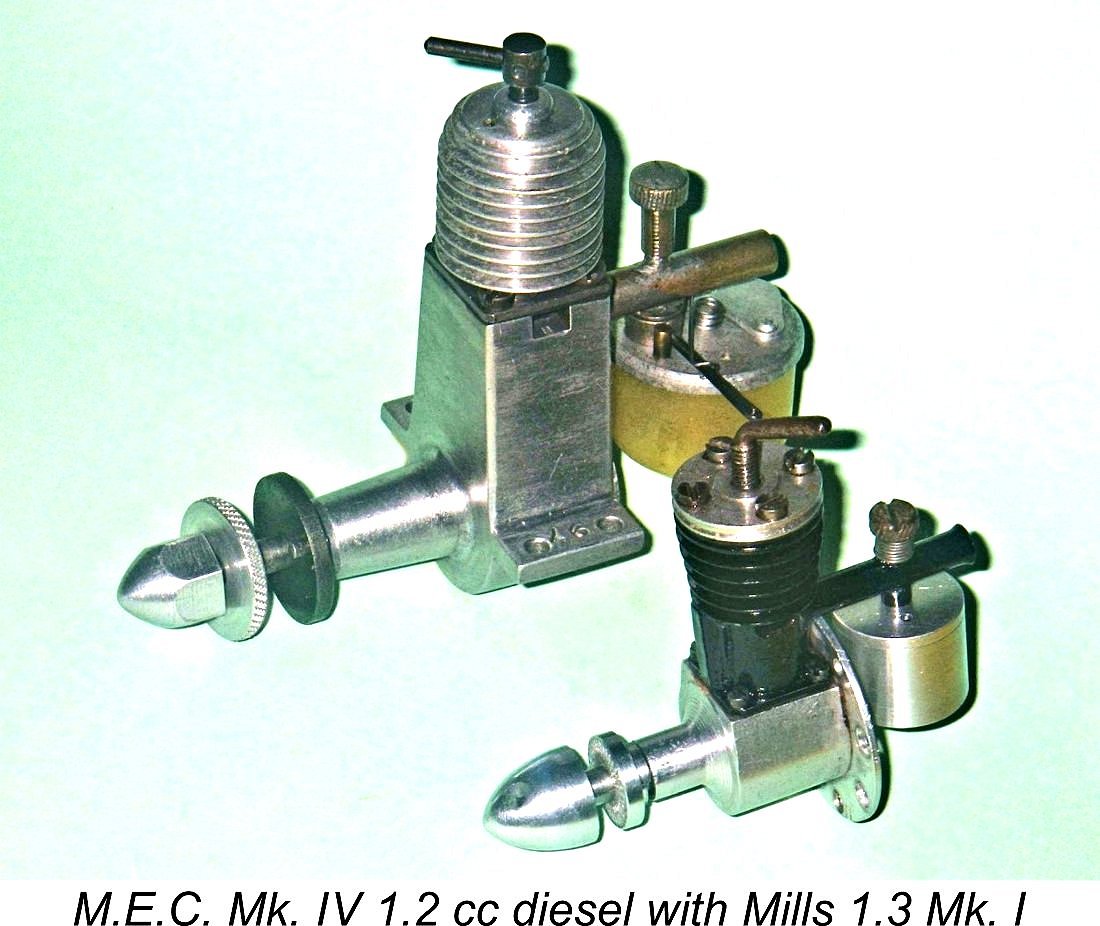 vogue in Britain at the time, with makers such as
 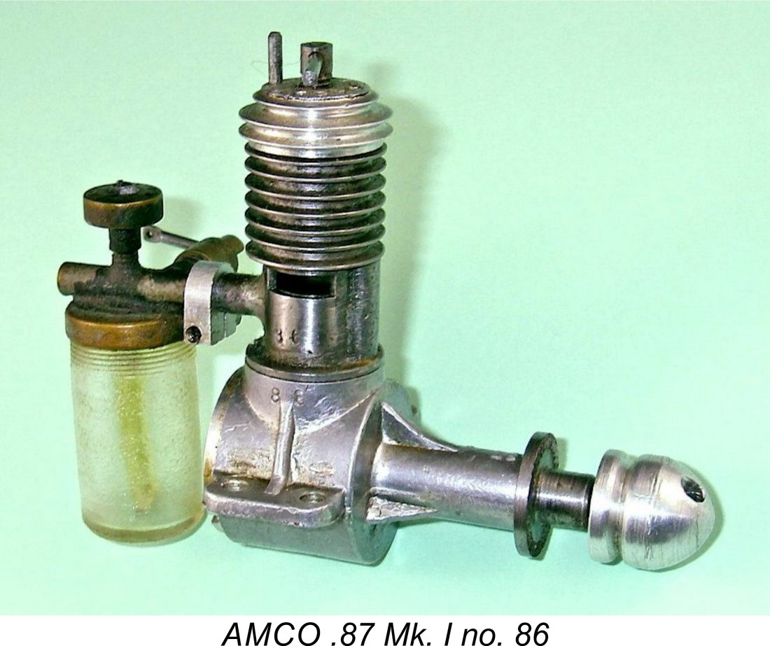 of somewhat lesser displacement. The only competing model to marginally beat this figure was the
 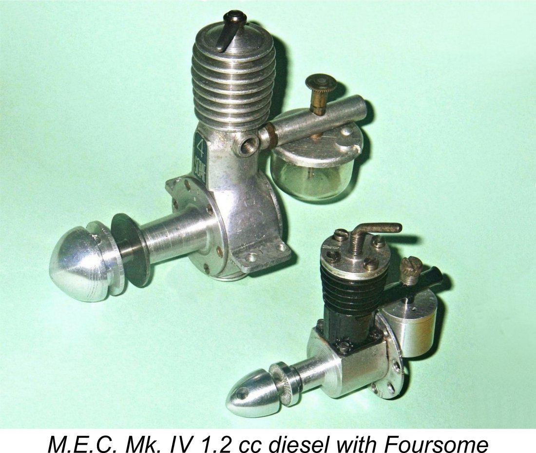 Engines of 1.2 cc displacement or thereabouts were not at all uncommon in Britain at this time - the famous London-made
 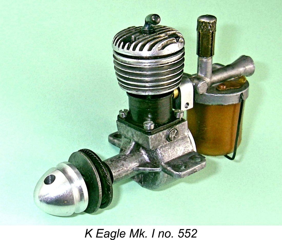 The price of the M.E.C. was more or less in line with that of its competition. Although its introductory price of £4 4s 0d (£4.20) was a little above the average, we saw earlier that the figure was quickly reduced to £3 15s 0d (£3.75). This was well above the remarkably low £2 12s 6d (£2.63) cost of the Foursome 1.2 cc from Brighton, but substantially undercut the Mills 1.3 at £4 15s 0d (£4.75), the M.S. 1.24 at £4 15s 6d (£4.78) and the Milford Mite Mk. III at £4 4s 0d (£4.20). The M.E.C. even undercut some smaller competing models such as the contemporary 1 cc side-port
 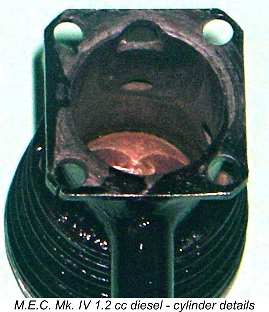 The thin-walled steel cylinder has integrally-turned cooling fins. It is attached to the aluminium alloy crankcase with four 8BA screws which pass through the corners of a square cylinder base flange. These corners actually appear to me to represent the most vulnerable points in the engine's structural integrity, since they are relatively insubstantial, looking as if a really hard blow to the cylinder could possibly fracture them. Otherwise, the unit appears to be quite sturdy, with adequate strength where it's most needed.
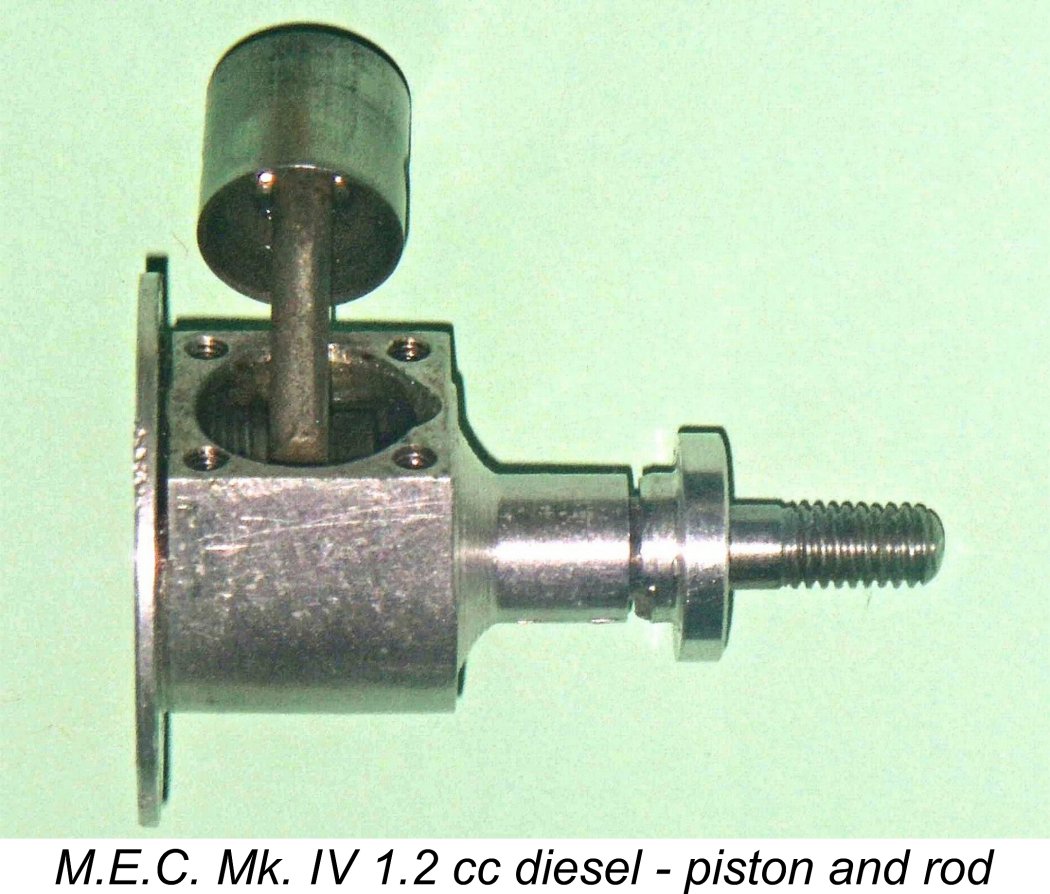 below the cooling fins, very much along the lines of the contemporary
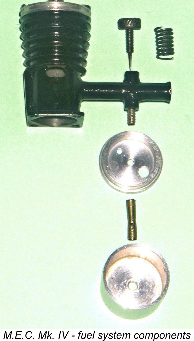
 As I see it, the fact that I’m fortunate enough to have a fine original example of the M.E.C. on hand effectively imposes an obligation to share the results of a comparative test to see how it compared with other contemporary offerings. If I don't do so, who will?
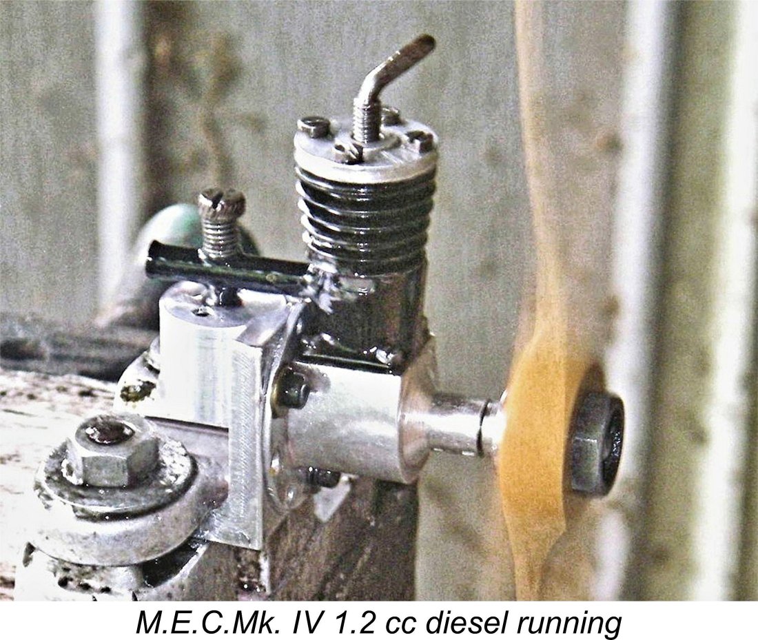 I started off with a 9x4 Top Flite wood prop on the M.E.C., setting the compression and needle valve controls by "feel" and guesswork respectively. After the tank was filled and a finger choke was given, I injected a small prime to offset the storage oil that remained in the engine, and two flicks later it was running! Amazing - after who knows how many years resting in collections?
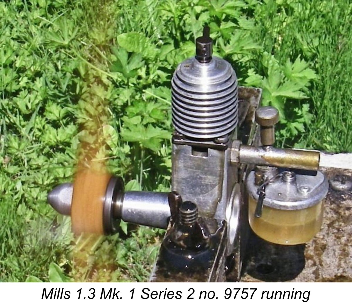 The tank supplied with the M.E.C. looks pretty small, and indeed its capacity is rather marginal for the engine's fuel consumption. A full tank gives a full-power run of only 40 seconds, including warm-up. Of course, this is adequate for sport free flight use, while the fact that the engine requires minimal fiddling once running means that there would be little delay between a start and the actual launch.
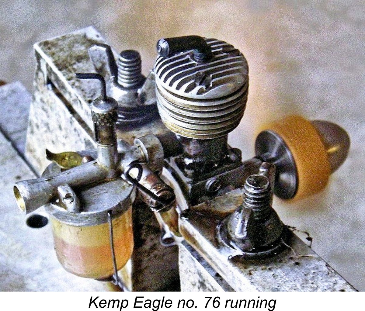 I didn't feel like putting too much time on the engine given that I wasn't planning to fly it, so I contented myself with taking readings during the first 30 seconds of running before the tightening began to take effect, causing the engine to slow somewhat towards the end of the run. The readings taken therefore represent the minimum performance of which this engine is capable - if well freed up, there's no doubt that it would beat these figures.
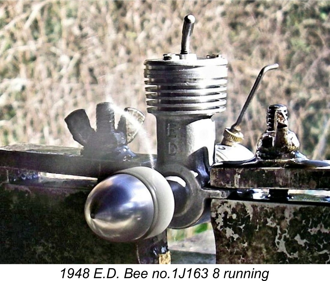 But not for long! Only one month after the M.E.C. was launched upon the market, Mills came out with their magnesium-case
 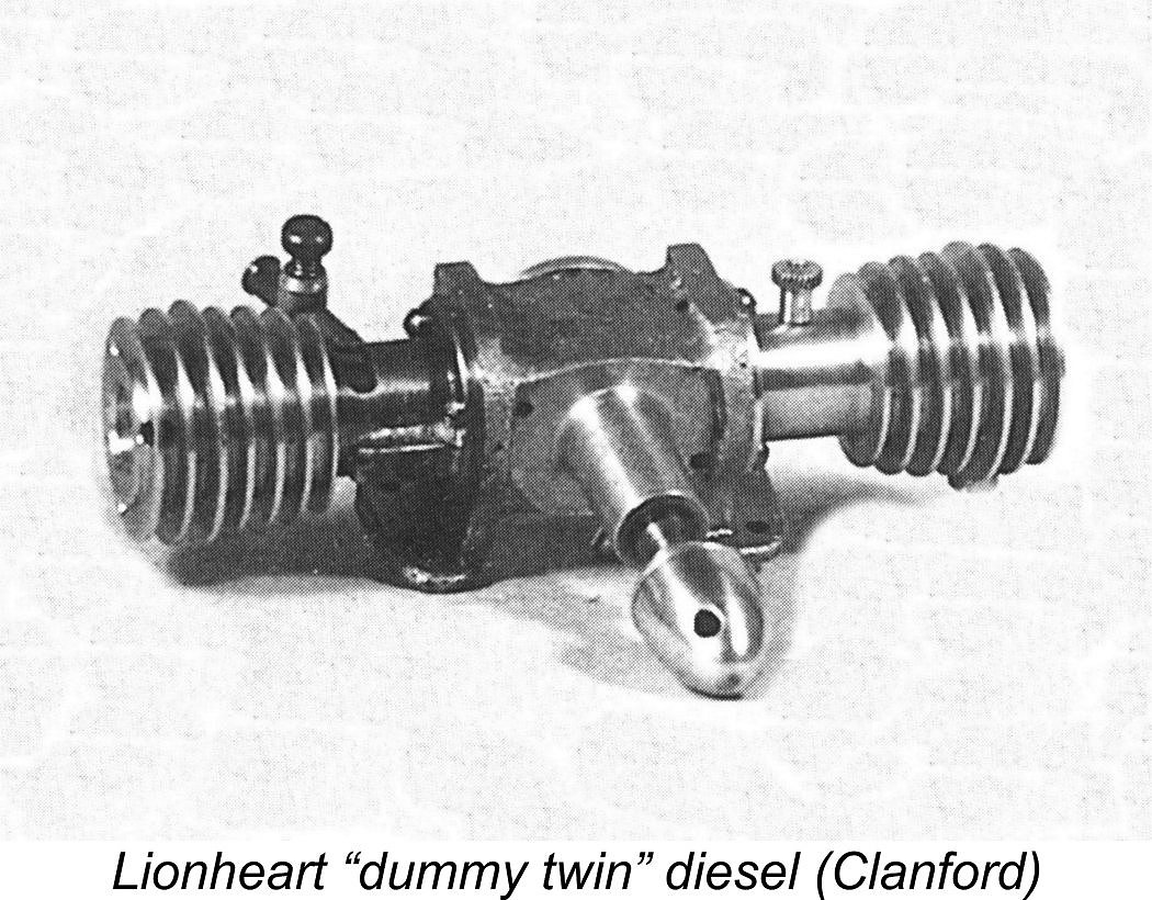 We saw earlier that the M.E.C. continued to be offered for sale by Premier Aeromodel Supplies up to July 1949. However, the M.E.C. was not alone! In late 1948, the Premier company had introduced a second model engine, this time under their own name. This was the 2.5 cc Premier Lionheart "dummy twin" side-port model, which was designed to be operable in both diesel and glow-plug modes without modification. This unusual engine was specifically marketed under the Premier banner - no mention of M.E.C.
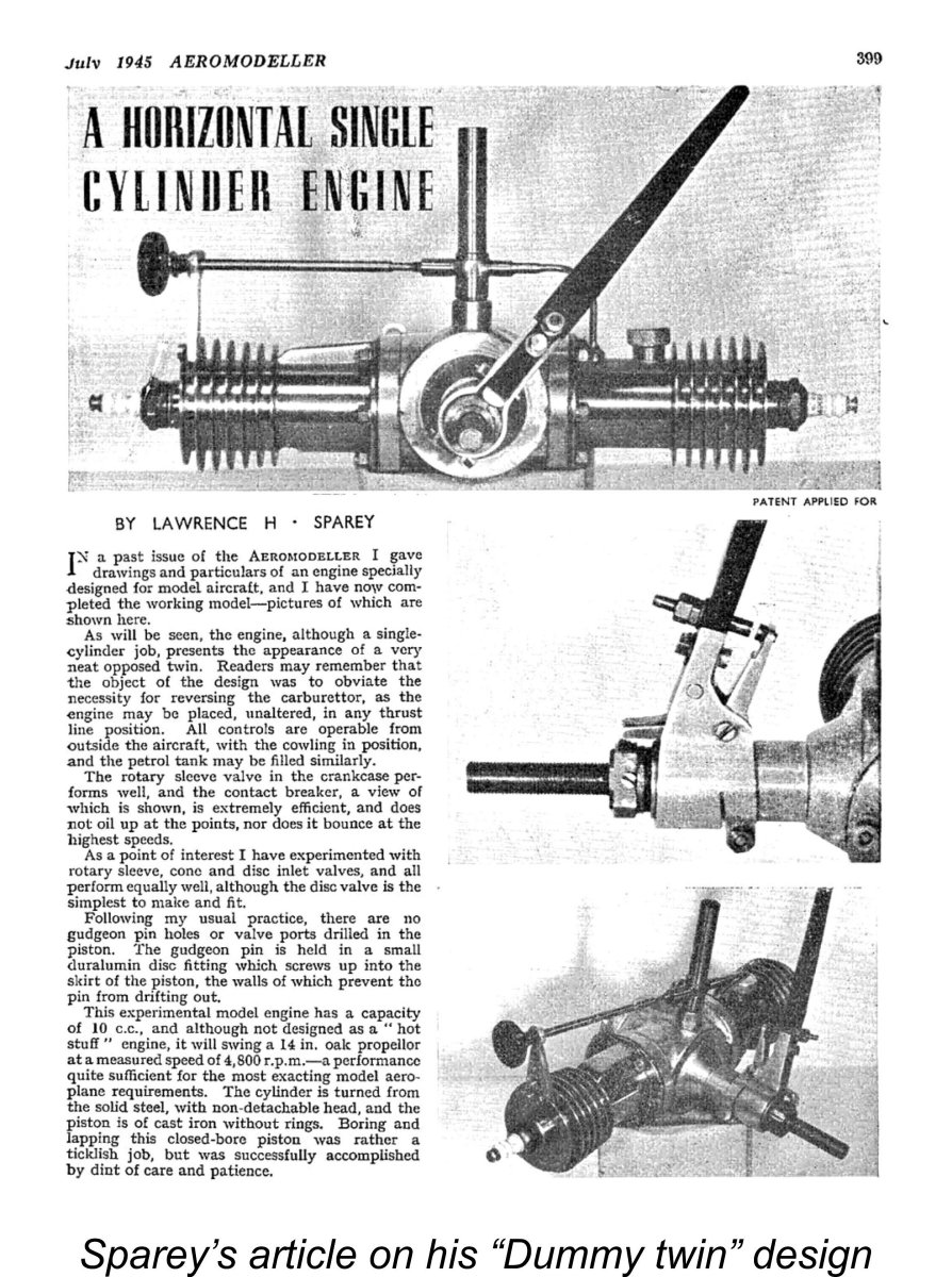
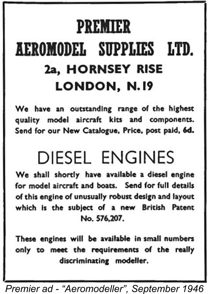 numbers only to meet the requirements of the really discriminating modeller”.
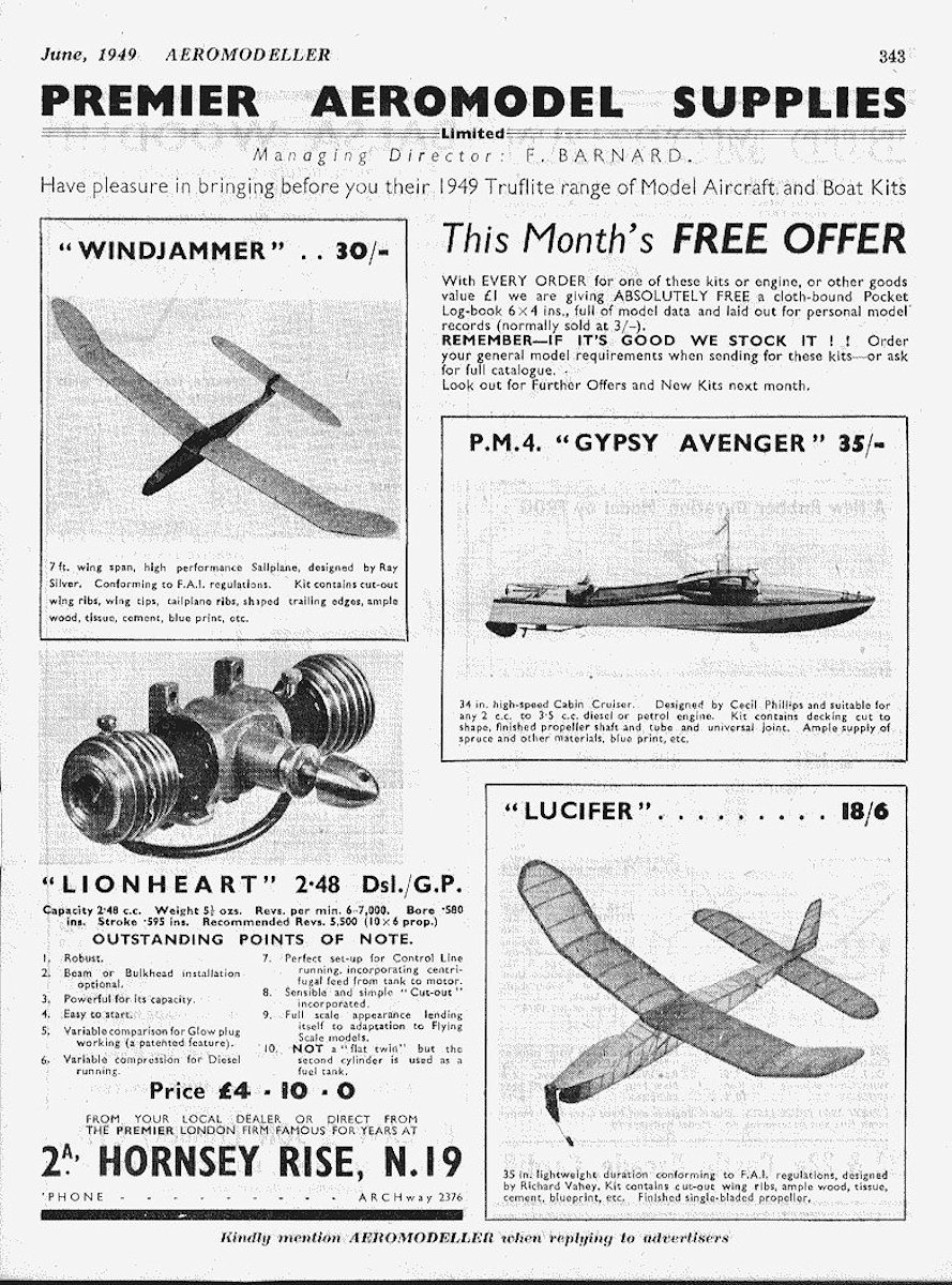
 Many parallels can be drawn between the M.E.C. 1.2 cc diesel and the contemporary
 | |