
|
|
Fun with the K&B Tornado .049
So why single out this particular unit for an in-depth review among all of the other possibilities, you may ask? For a number of reasons - first, because I’ve always been attracted to engine designs that were technically different, and this one certainly fits right into that category! And second, because of my attraction towards engines of comparative rarity. The K&B Tornado .049 seems to be one of the less commonly-encountered mass-produced American ½A engines from the “classic” era, at least in original condition. This is largely because many of them - perhaps the majority - were not sold as hobby engines, instead being used as powerplants in a line of Ready-to-Fly (RTF) models produced by the Aurora Plastics Corporation. When the model broke (as they almost always did eventually), many of the engines simply got thrown out with the planes. The Aurora connection in itself may be another reason why the Tornado .049 has perhaps been less highly regarded and less carefully conserved than it deserves to be. The Tornado’s close association with Aurora and its plastic RTF models as well as the extensive use of plastic in the engine’s construction has imparted something of a “toyshop” image to the Tornado, placing it on the sidelines in the eyes of a sizeable number of collectors who are attracted to “real" hobby engines. A pity, because it’s a far better engine than that! This is another motivation for the preparation of this article - the Tornado is fully deserving of having its reputation greatly enhanced.
This operational neglect is due at least in part to the fact that the special glow-heads produced for the engine are in short supply. Most of those that do get run are fitted with original heads which have been centrally drilled and tapped to accept a standard glow-plug, with an undetermined effect upon performance. New original glow-heads can still be purchased from MECOA, but they’re not cheap - US$21.99 last time I looked in 2024. I’ll suggest a few alternative approaches below. Another factor which seems to discourage both the running of these engines and perhaps even the attention paid to their preservation is the unusual design of the induction valve. This unique system has characteristics all of its own, as we shall learn. Some of those characteristics evidently discourage owners from giving the engine a try, also encouraging unwarranted disturbance of the assembly with generally negative results. I’ll be discussing this highly original set-up in detail in a later section of this article. Having managed to acquire several examples of the Tornado over the years, I decided to take a closer look at what made the engine tick. It turns out that in a number of respects these are highly individualistic units displaying several quite unusual and technically interesting features that set them apart. Let’s take a closer look …………. Origins
The latter provision was most likely in response to the chronic and well-documented spring failures which bedeviled the heavy, bulky and costly Rotomatic starters fitted to the Wen-Mac RTF engines. This had given starters a rather tarnished reputation. Aurora clearly wished to avoid falling into the same trap, perhaps also wanting to save some weight as well as a little cost. That said, a number of examples of the Tornado have shown up with Cox coil spring starters having been retro-fitted by their owners. An example of such a fitting appears in a later illustration below. K&B had amalgamated with Allyn Manufacturing in 1955 and were still trading as K&B-Allyn as of 1959. Oddly enough, the amalgamated company had somehow become owned by Nabisco - I have no idea how or why that came about! However, that relationship didn’t last long.
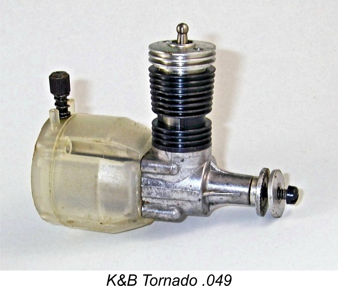
The engine appeared in the spring of 1959, being branded at the outset as the Aurora Tornado .049. This identification was stamped in very finely-formed characters onto the underside of the crankcase - no mention of the engine’s K&B origin. At this stage, the Tornado sported a translucent white Delrin plastic fuel tank and backplate. One assumes that these components were produced by Aurora, since plastics were their business. The name Delrin denotes a high-strength mouldable plastic polymer (Polyoxymethylene, or POM) which had been first discovered in Germany in the 1920’s and further refined by DuPont in America into a commercial product as of the mid 1950’s. It offered high tensile strength; considerable stiffness; high resistance to creep and fatigue; and The combination of these excellent mechanical properties in a single plastic material allowed for thinner, lighter-weight parts and shorter moulding cycles with potential cost reductions. It was also readily amenable to the addition of coloring agents as well as being highly resistant to solvents such as those found in model engine fuels. Following its spring 1959 appearance in production form, the Tornado was sold exclusively to Aurora for use in their RTF models, not being placed on the hobby market at this time. The exclusive use of the Tornado by Aurora continued for a full year until late April 1960. Even so, tens of thousands of these engines were supplied to Aurora during that year. The Tornado was featured in Aurora’s L19 Bird Dog and P-47 models among others.
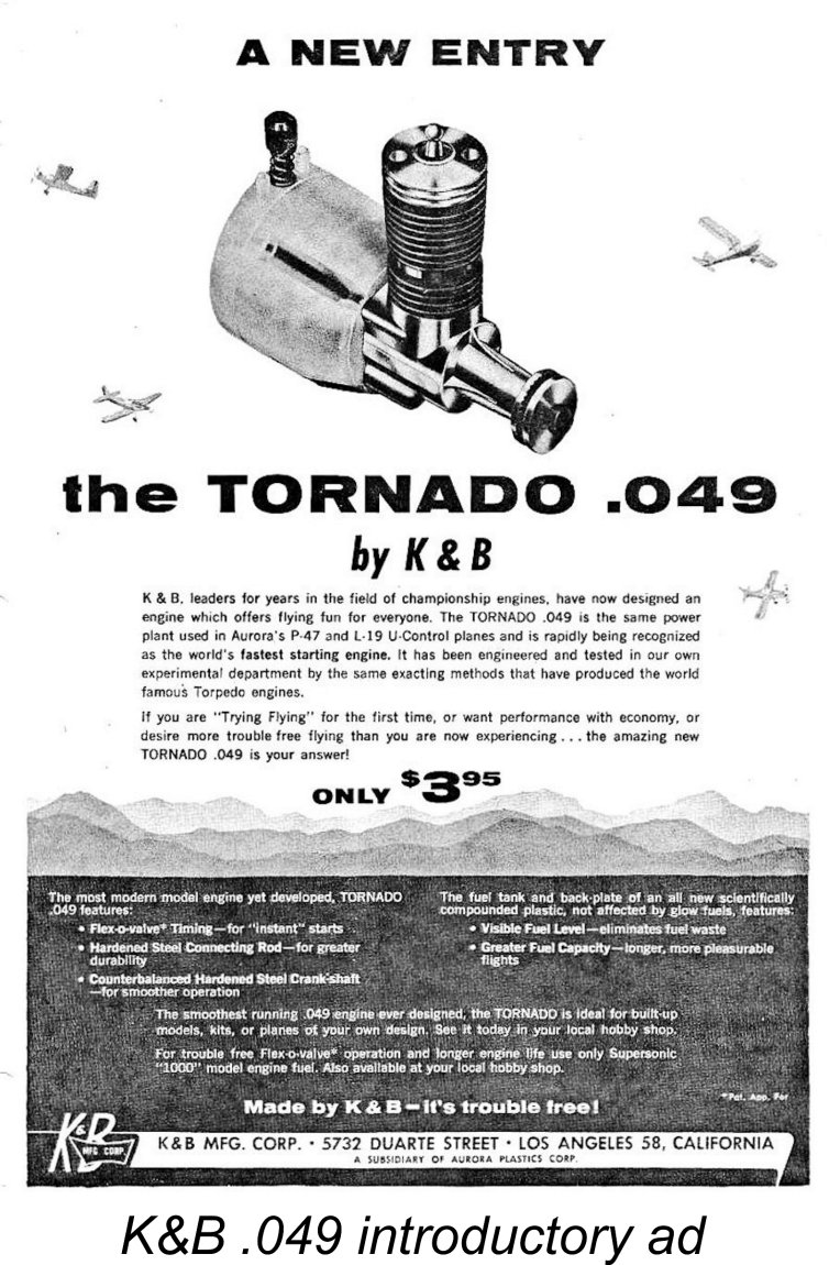
Following the early 1960 acquisition of K&B by Aurora, the Tornado finally became available as a stand-alone hobby engine, being marketed in that form as the K&B Tornado .049. The K&B .049 identification was stamped onto the underside of the crankcase in place of the former Aurora designation. At this stage, the white Delrin plastic tank assemblies were retained. These hobby engines first appeared in the shops in late April 1960, being sold in carded bubble packs as opposed to boxes. The selling price was a very reasonable $3.95.
In developing this variant, the company was doubtless responding to the failure of the .049 model to provide sufficient "urge" to fly the increasingly heavy and aerodynamically-inefficient RTF control-line models of the day. It's interesting to note that Herkimer, who supplied engines to the competing Comet company, had been forced by similar considerations to take a parellel step with the introduction of an .059 cuin. version of their .049A reed valve model of 1960. The .060 variant of the Tornado retained the same stroke as the .049 variant, but used a revised cylinder design featuring a larger bore along with twin transfer flutes as opposed to the single flute provided in the .049. These transfer flutes were necessarily a little shallower than the single flute used in the .049 due to the thinner cylinder wall imposed by the larger bore of the .060. Moreover, the sub-piston induction featured in the .049 model was eliminated in this model. Nevertheless, despite the continued use of the .049 induction system to supply the .060, we might expect a useful performance increase to result from the increased displacement allied to the additional transfer port.
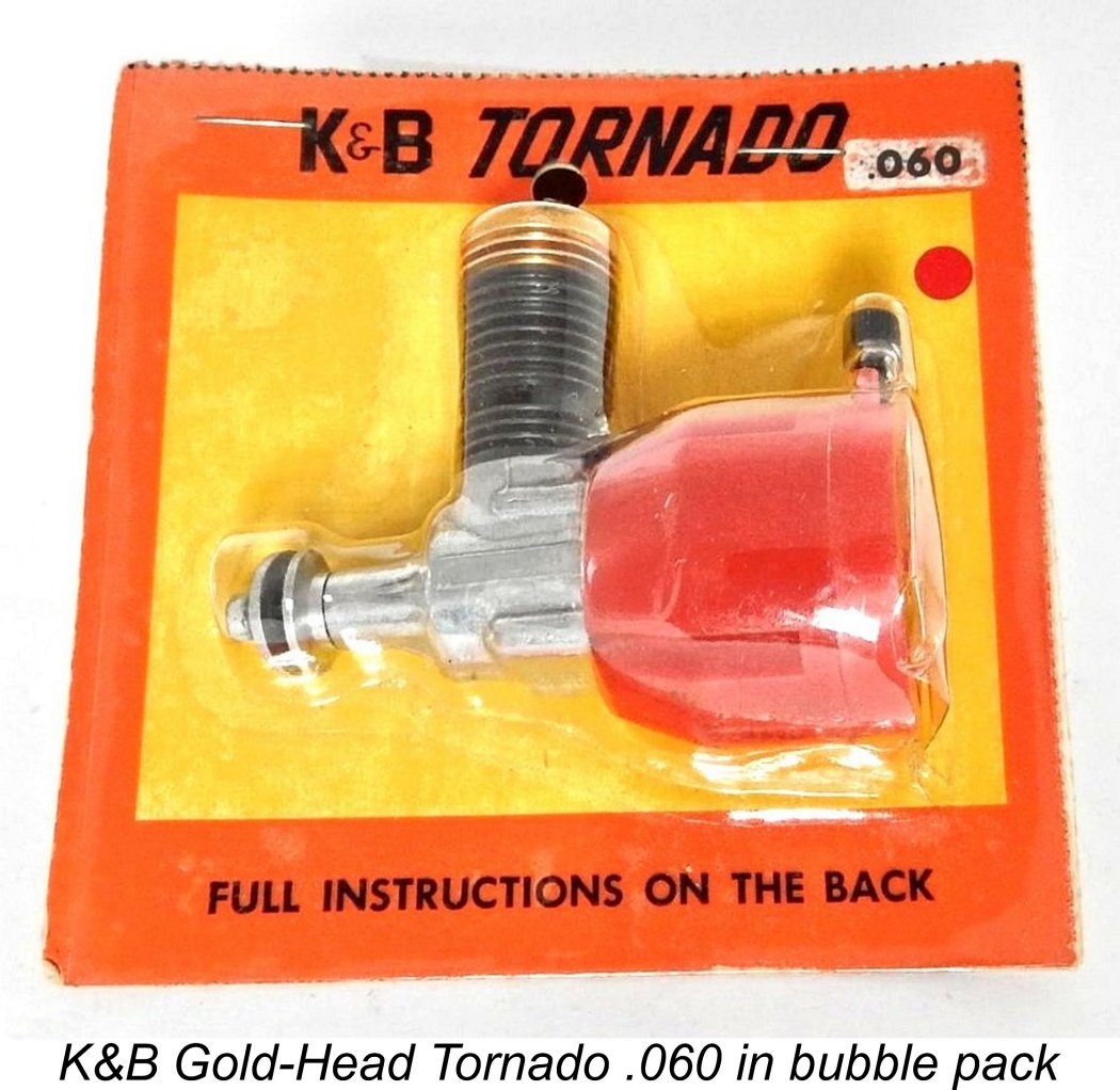
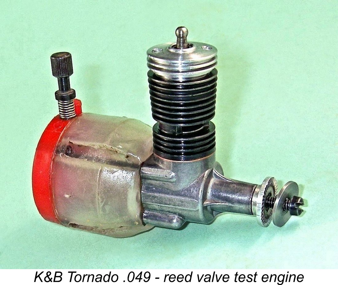
At some point along the way following the Aurora takeover, the induction valve design in both the .049 and .060 models was changed to a more standard Cox-like arrangement with a thin bronze-sheet reed. It appears that either the flex-o-valve component was found wanting in some respect or there was a desire either to cut costs or side-step a supply issue. More of this below in its place. A later variant of the reed valve .060 was introduced in March 1963, still with a red tank but now having a gold-anodized head. This change may in fact have coincided with the switch to conventional reed valve induction. The image at the right shows such an engine still in its bubble pack.
The .060 model is significantly less commonly encountered today than the .049 version, presumably because relatively few of them were sold as hobby engines - the marketing emphasis at the time was very much slanted towards the AMA ½A category, for which the .060 was ineligible. Most of the .060's were used in RTF models and were thrown out with the models when the latter gave up the ghost. It appears that as of early 1963 plans were already well advanced to replace the Tornado with the more powerful crankshaft front rotary valve (FRV) K&B Stallion .049 which appeared in May 1963. Production of the Tornado did continue for a time, both to use up parts already on hand and to maintain a supply of engines for Aurora to use in their ongoing RTF models which had been especially engineered for the Tornado. The supply of white Delrin rear tank covers seems to have run out before the white tanks, because some of the later examples of the .049 have white tanks with red rear tank covers. All Tornado production had seemingly ended by late 1963. Description I won’t spend too much time on this section, since the general mechanical design of the Tornado follows the familiar pattern established earlier by Cox in almost all respects. The main functional difference is the induction control valve, which fully deserves its own later section of this article.
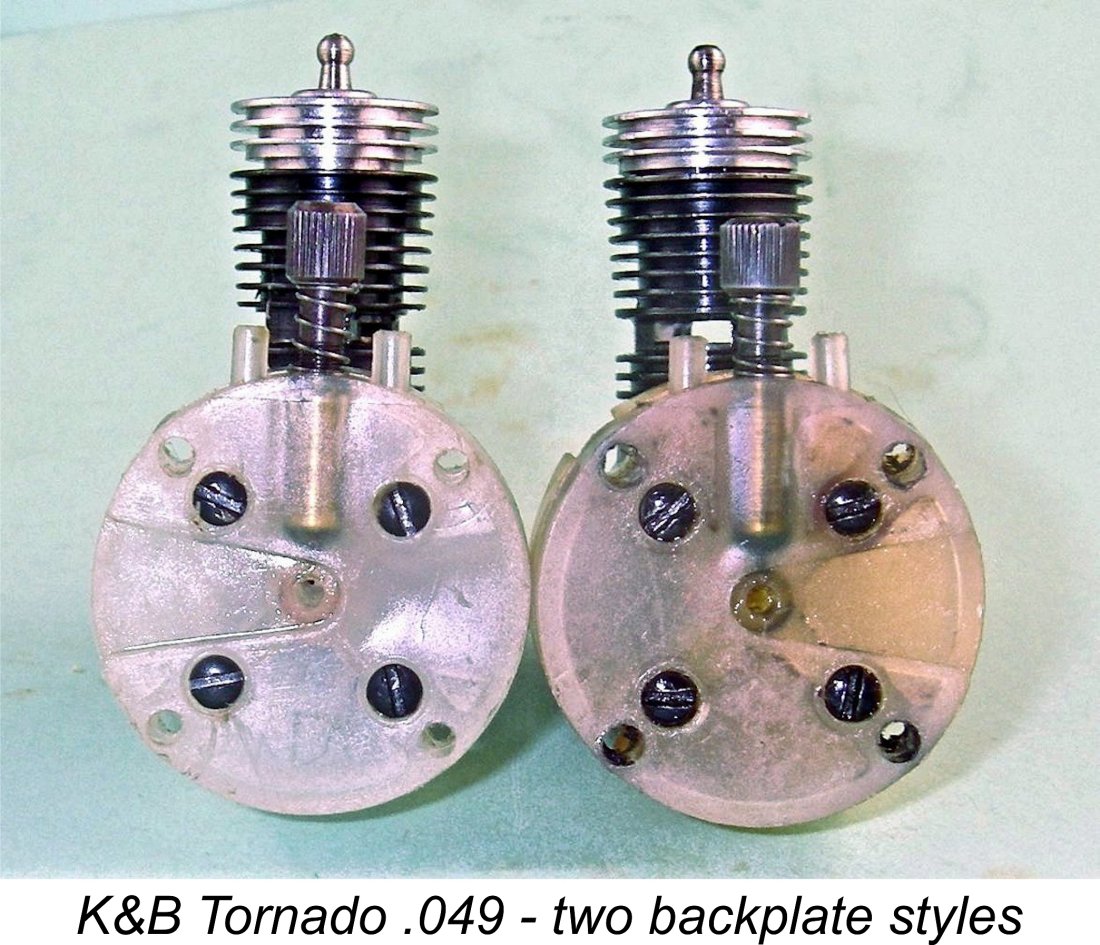
The .060 model used the same stroke, but the bore was increased to 0.430 in. (10.92 mm) to raise the displacement to 0.0572 cuin. (0.94 cc), still with a perfectly reasonable 1.07 to 1 bore/stroke ratio. In all other respects apart from the tank colour, the two engines were identical. The Tornado .049 weighed in at 48.2 gm (1.70 ounces) complete and ready to run with tank. This compares very well with the Cox Babe Bee at 49.6 gm (1.75 ounces) and the Golden Bee at 53.3 gm (1.88 ounces). The Tornado followed the general design pattern established by Cox with their Babe Bee of 1956 and continued with their 1958 Golden Bee. Apart from the cylinder shape, the main change to the actual power unit was the Tornado's use of a pressure die-cast crankcase instead of the Cox’s case machined from extruded bar stock. The cylinder was a screw-in component machined from steel, blued and left unhardened. It was provided with thin integrally-formed cooling fins. Porting followed the Cox Bee pattern exactly, with two opposing exhaust ports The hardened steel piston was joined to the conrod using a swaged ball-and-socket joint, again exactly like the Cox. The hardened steel conrod drove a counterbalanced one-piece crankshaft of the same material. This had a tapped hole at the front to accommodate the prop retaining screw. The prop driver was mounted on a splined length of the crankshaft at the front, with a slot-head screw and light alloy washer used for securing the prop. Again, all of this followed the Cox pattern exactly. Apart from the material used, the Delrin tank too followed the Cox lead very closely, although it had a greater fuel capacity. It incorporated an induction tube along its central axis which was supplied with fuel through a surface jet at the rear. This jet was located inside the tank’s separate Delrin backplate, which included a tapered radial channel running out to the perimeter to supply air to the engine. The externally Fuel reached the needle valve through a length of flexible fuel tubing inside the tank. Oddly enough, two distinct tank backplates were used. Viewing the backplate from the rear with the needle at the top, some examples had an air duct running out to the right side while others sported similar ducts which ran out to the left. One supposes that the choice of backplate depended on the application. The tank and its backplate were secured to the actual powerplant using four long screws, with a fibre gasket being used at the front to ensure a crankcase seal. The heads of these screws were countersunk into the backplate to maintain a flat mounting surface. Since the placement of the tapped holes in the crankcase to accommodate these screws was a perfect square on a common pitch circle around the central axis, the power unit could be mounted in any desired orientation relative to the tank. A word to the wise - don't over-tighten these screws! The tank material is very strong by plastic standards, but it can still distort or crack if excessively stressed. Tight enough and no more is the goal at which to aim. Four additional holes were provided in the tank and backplate to allow the engine to be radially mounted against a bulkhead. One positive change from the Cox design was the abandonment of protruding “mouse ear” radial mount lugs in favour of internally-recessed openings near the perimeter - a far stronger arrangement, especially when using plastic components. So far we’re talking about a slightly re-styled version of the Cox Babe Bee! However, I’ve saved the best for last - the induction control valve. This represented such a radical departure from the standard Cox design that it’s well worth a section all to itself. The Induction Valve
The induction tube which passes through the axial centre of the tank is completely conventional. It terminates in a very large-diameter bell-mouth recess at the front which is contained in the protruding tank installation spigot. The tank installation spigot features a slightly expanded external lip at the very front so that it is a smooth but rather tight plug fit into the rear of the crankcase, effectively “snapping” into place. This explains why considerable resistance will be encountered when removing the tank from the engine - this is completely normal.
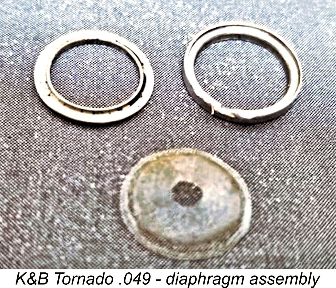
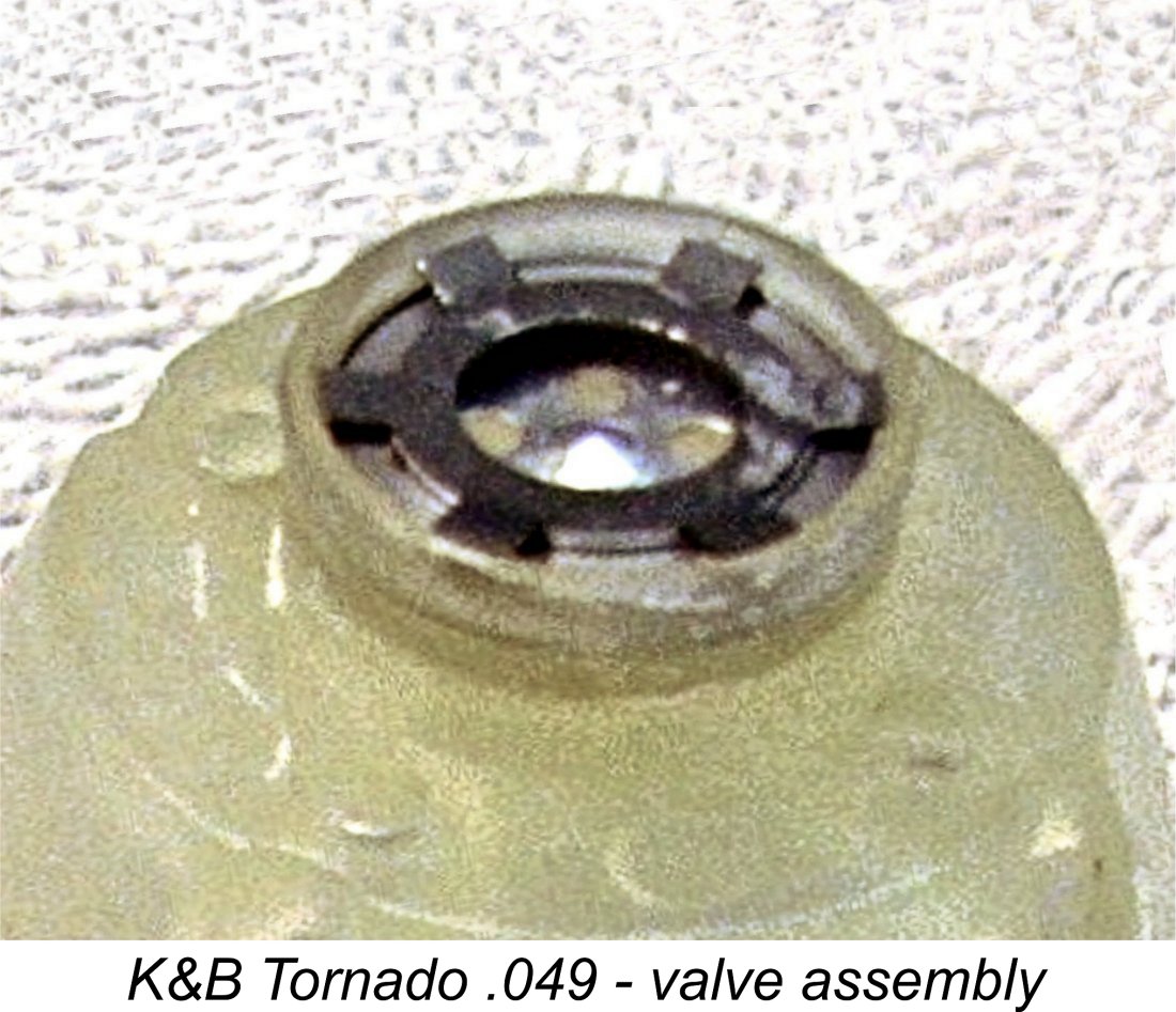
The next component is a composite circular diaphragm formed from 0.003 in. thick Mylar plastic. This diaphragm is permanently Finally, the two components already described are retained in position by a six-armed metal keeper which snaps into place onto a shelf formed at the front of the valve recess. This keeper has a large circular opening at its centre, thus presenting no impediment to the passage of incoming mixture. The external raised lip at the crankcase end of the tank installation spigot clearly has the function of "squeezing" the recess into which the keeper fits, thus increasing its security.
Conversely, when the pressure in the crankcase becomes positive as the piston descends during the power stroke, the Mylar diaphragm is forced back to close both the five holes and the central hole associated with the dome. These actions seal the valve, allowing the build-up of positive crankcase pressure to drive the transfer phase. Considering the geometry of the design, it would appear that the main seal is intended to be created by the central hole in the diaphragm in effect "wrapping" itself around the base of the central dome in the backplate. This is a perfectly logical and readily understandable variation on the reed valve theme. However, John Brodbeck very intelligently took this idea one step further. The Tornado is provided with a short but potentially significant period of sub-piston induction around top dead centre. This is a far more positive feature than might be supposed - indeed, in my personal opinion the use of sub-piston induction in a reed valve or equivalent design is theoretically almost a necessity if maximum performance is to be achieved.
It's a little odd that more manufacturers of such engines didn’t recognize and apply this principle. The German makers of the Taifun reed valve engines certainly did, and to very good effect at that. I’m actually more than a little surprised that Cox missed this one - sub-piston induction has been found to benefit their reed-valve engines to a remarkable degree. The addition of around 25 total degrees of sub-piston induction to a Cox Golden Bee by carefully grinding the bottom of the piston skirt has an astonishingly positive effect on performance - I’ve tried it! Hopefully the above explanation will have clarified the design and operation of John Brodbeck’s very ingenious but somewhat complex “flex-o-valve”. A few points of guidance for owners of these engines are now in order. First, don’t even think about messing with the diaphragm assembly! As previously illustrated, it is possible to pry the two halves of the retaining ring apart to release the diaphragm, but reassembly is almost impossible. Best not to go there! Even removing the diaphragm with its retaining ring left undisturbed can be problematic because any slight distortion of the ring during handling or reassembly can create a crease in the diaphragm, causing it to lose function. Moreover, it would be easy to damage the diaphragm when prying out the components. Best left alone! After running the engine on a fuel ontaining castor oil, it's important to flush any residual castor oil out of the valve if long-term storage of the engine is envisioned. If the diaphragm becomes "glued" to the valve backplate with castor gum, any subsequent unsticking process has a high potential to cause damage to the very delicate diaphragm. The other issue associated with this valve is that it doesn’t seem to function in the same fashion as a conventional reed valve. The usual test for reed valve effectiveness is to alternately suck and blow through the induction tract (most conveniently from the front) to check that air can pass in one direction only. Applying this test to the flex-o-valve can give highly misleading results. The issue seems to be that when at rest, the diaphragm has no sealing force of its own, allowing air to pass in both directions. It appears that in order to function correctly the flex-o-valve requires fairly high gas velocity fluctuations arising from rapid and substantial crankcase pressure variations, both positive and negative. Because of this, most examples of the flex-o-valve fail miserably when subjected to a conventional suck-blow test. This causes their owners to assume that they are non-functional and either to discard the engine, try to repair the flex-o-valve (usually with highly negative results) or attempt a replacement with a more conventional reed valve. However, the failure of a flex-o-valve to show well in a suck-blow test turns out to be no indication whatsoever that it will not function when the engine is in operation. My own test example of the engine (see below) failed miserably in a conventional suck-blow test. And yet it performed on the test bench at a very high level, as I’ll document in a later section of this article. The only way to confirm whether or not one of these valves is functional is to try to run the engine! Neither my "experienced" test engine nor my seemingly unused LN example exhibit the slightest sign of any transfer “pop” when turned over with the head removed. However, if the prop is hit team-race style to really spin the engine with the head removed and a little oil injected into the valve, they pop just fine. The key is to create sufficient speed to promote high fluctuating gas velocities through the valve. Basically, the valve is only functional under dynamic conditions above a certain speed. Once that point is reached, it clearly works very well. The Reed Valve Variant
I might have put these reports down to cases of owner intervention were it not for the fact that my good mate Maris Dislers sent me an incomplete example of the Tornado .049 which was equipped with a Cox-style reed valve. Maris believed this to be a case of owner intervention. However, upon disassembling the unit for inspection it turned out that this tank was specifically modified to accommodate a reed valve installation. Only the factory could have done this. The most obvious change is a significant reduction in the diameter of the bell-mouthed cavity at the delivery end of the induction tract. This change was clearly made to facilitate the use of a reed of reasonable size. Moreover, the reduced cavity was provided with a raised lip around its outer circumference with the clear purpose of providing the reed with a suitable annular seat against which to seal. A narrow shelf was also provided around the perimeter of what was clearly intended to be a base for the reed. All of these features are readily apparent in the accompanying image. Instead of the shelf which accommodated the keeper used to retain the flex-o-valve (see above), the crankcase end of the tank installation spigot now featured an internal groove which was clearly intended to accommodate a circlip or similar - the former keeper would not fit. In fact, the whole set-up is virtually a clone of the Cox design, to the point that a Cox reed and circlip both fit perfectly. Hopefully all of these details will be apparent from a close inspection of the accompanying images.
I fitted new Cox components to the tank on Maris's incomplete engine (which was missing its cylinder and featured a damaged reed as received), finding that the re-assembled reed valve passed its “suck-blow” test with flying colours. I anticipated that this valve would work very well in service. I'll present some actual test results below in their place. There is presently some residual doubt regarding the precise form of the reed valve used by K&B with this tank. As stated above, a Cox four-armed reed and retaining circlip both fit perfectly, but I have also found the accompanying photograph below at the right showing a three-armed reed as opposed to the four-armed Cox component.
The factory switch to reed valve induction probably dates from the final year of production, when the decision had already been taken to replace the Tornado with the crankshaft front rotary valve (FRV) Stallion .049. We saw that the company ran out of the white tank backplates prior to the end of Tornado production - the incomplete reed valve unit supplied by Maris had a red tank backplate, as do many other examples. The same may have been true of the flex-o-valves. Rather than making more of those relatively expensive single-application items for a design on which the sun was already setting, the company may have simply gone the cheap ‘n easy route by switching to a conventional reed valve for the later examples. The required changes to the tank die would have been implemented very easily. The Glow-Head
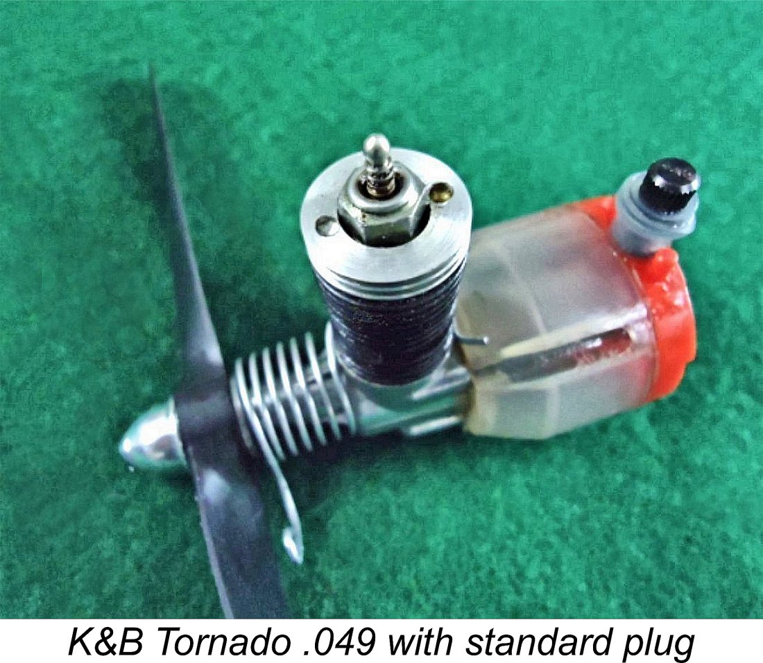
Even if you have the proper tool, a common difficulty with removal of a glow-head of this type is the cylinder unscrewing instead of the head. This is a particular problem if an attempt is made to remove the head from a hot engine. Do not insert a screwdriver blade or equivalent into the exhaust ports to hold it - you’ll ruin the cylinder irreparably if you do. Cox provided a rectangular slot in one end of their head wrenches which just fit over the exhaust ports to prevent the cylinder from turning without marring the cylinder bore while another similar tool was used to turn the head. However, the width of the slot in the Cox wrench is marginally too small to fit over the Tornado exhaust ports. It’s easy to take a spare Cox wrench and widen the gap with a few strokes of a file until it just fits over the Tornado’s ports. End of difficulty ……. You can of course make your own tools from scratch if you don’t have any spare Cox wrenches. The limited availability of original glow-heads is a major disincentive to consider actually using or even just running one of these engines. If a given example has a functional glow-head, the owner will naturally want to conserve it. As I mentioned earlier, new The easiest and most obvious option is simply to centrally drill out a burned-out Tornado head and tap it ¼-32 (not ¼-28 - a common error!) to accept a standard glow-plug. Many examples of the Tornado are encountered with such conversions - a typical example is illustrated here. However, heads modified in this way often perform at a measurably lower level than an original head with integral element. They also alter the engine’s appearance quite significantly. Note the Cox spring starter which has been retro-fitted to this example. Before tackling such a conversion, you have to remove the If you go this route, check frequently when cutting the seat for the plug to ensure that the tip of the installed plug (with washer) exactly matches the surface of the surrounding combustion chamber when fully tightened. If you take care over this, the resulting head should theoretically yield a very similar performance to that achieved with a standard unmodified glow-head, although in practise a small drop in performance is usually experienced. When you re-install the head, don't forget the copper sealing washer!
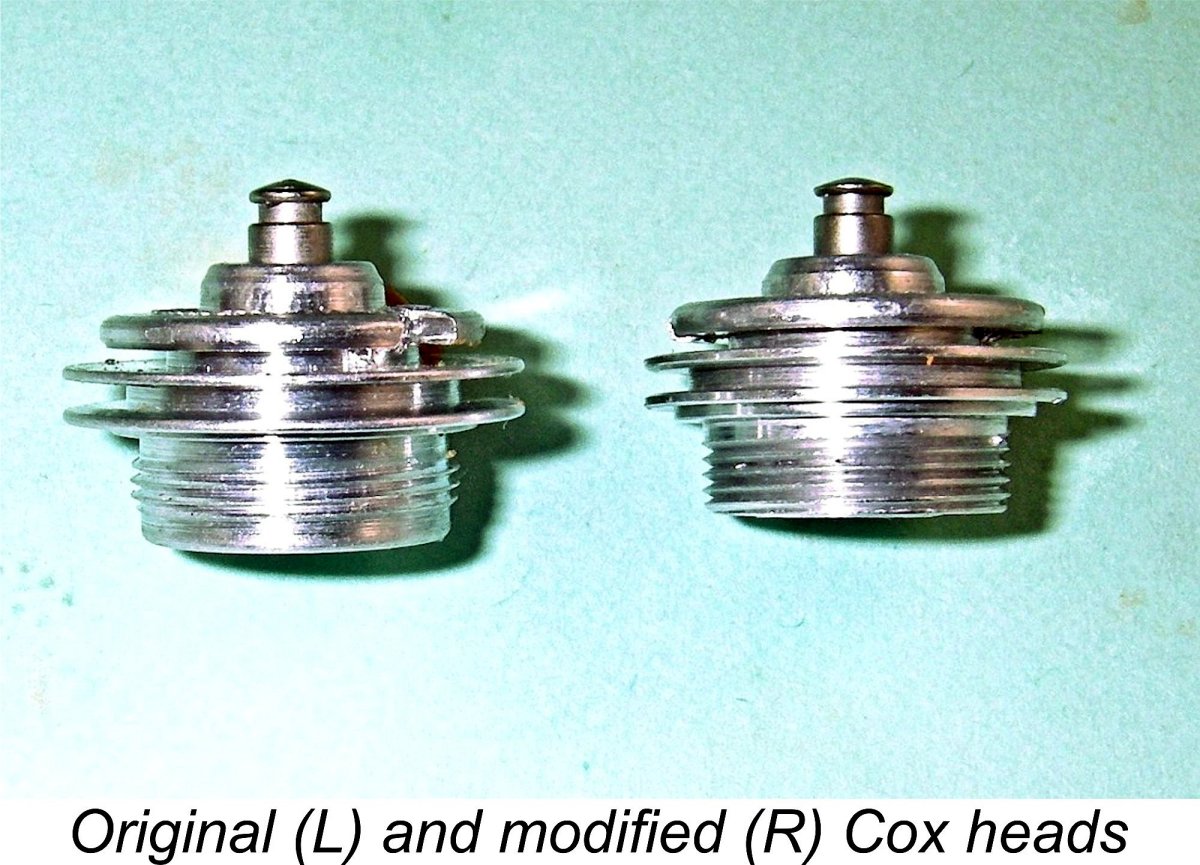
A somewhat more unusual approach offering an enhanced performance potential is the conversion of a Cox .049 glow-head to fit the Tornado. This is surprisingly easy to do if you have access to a lathe. Many of us have a handful of those heads lying around waiting to be used - they’re far more common than the Tornado equivalents. As supplied, the Cox glow-head installation thread is fractionally larger than that used in the Tornado. This is very convenient, since it allows the Cox installation spigot to be re-machined to suit the Tornado. If you're set up for the task, a conversion only takes about 20 minutes.
Whichever head you use, begin by turning the installation spigot down to 0.500 in. diameter, removing the Cox threads in the process. Then cut a new 40 tpi thread onto the reduced sized spigot, which will permit its installation in the Tornado cylinder. This ½-40 thread is a standard UNS thread for which dies are available. However, if like me you don’t have such a die (they’re expensive and have very limited applicability), you can use the lathe’s thread-cutting capability. My little hand-turned Sherline thread-cutting lathe works very well.
The amount of material removed will establish the compression ratio, which is thus within your control. You can also experiment with different combustion chamber shapes. It is these options which give this approach perhaps the greatest performance potential. For cosmetic reasons, I also turn the outside diameter of the head fins down to match that of the Tornado cylinder. Such heads don’t look in the least out of place, also performing very well indeed in actual use, as we shall soon see. They can also be removed and re-installed using a standard Cox wrench - very handy! Tank Substitutions I don’t advocate the unnecessary replacement of original components on any classic engine with parts from a completely different motor. However, the Tornado cannot run without a backplate which incorporates both a reed valve (or equivalent) of some kind and a carburettor. Since many examples have damaged or missing flex-o-valves, while others may have damaged tanks or missing needles, this can be an issue which precludes the actual operation of one of these engines.
The other issue is that the Cox assembly screws have a slightly smaller thread diameter than those used by K&B - you have to use the K&B screws or equivalent. This means that the holes in the cast metal tank backplate used by Cox have to be very slightly enlarged. Regardless, there’s no doubt at all that a functional Tornado power unit can be restored to usefulness very simply through the fitting of a Cox tank assembly. Somewhat strangely, despite the smaller thread size the countersinks for the tank assembly screw heads are larger on the Cox than they are on the Tornado, hence possibly requiring some I’m reliably informed that hybrid engines created in this way run perfectly well. I’ve never tried such a modification myself beyond assembling an untested unit to illustrate this article as seen above. However, I see no reason to doubt the reports which I’ve received. The not-infrequent appearance of such hybrids on eBay confirms that they must work well, since a fair number of owners appear to have tried this approach with some success. There have been a few very constructive approaches to modifying the Tornado for other applications. The lengths to which some people have gone in that regard is an eloquent testimony to the perceived merits of the basic engine as a model powerplant. A notable example is the illustrated beam mount conversion constructed by the very talented Leo Squires. His all-new backplate converted the engine to beam mounting, also eliminating the back tank so as to permit the use of a tank of the modeller's own choosing. I don't have full details, but I assume that this fine-looking hybrid used Cox reed valve components. My only reservation would be the design of the beam mounts - I would expect vibration-related cyclic stresses at the rear end of the beams to be quite substantial, quite possibly leading to an early fatigue failure in service. The Tornado .049 on Test
Although worded slightly differently to reflect their different readerships, the two reports are essentially identical in terms of their findings. Hence they can be summarized as one. Chinn expended a great deal of space extolling the Tornado’s extremely easy starting. He put this down to a combination of an excellent piston fit, appropriate cylinder porting design and the effectiveness of the “flex-o-valve”. He described the latter component in some detail. The manufacturers apparently specified a high nitro content fuel (K&B Supersonic 1000) for use in this engine. Chinn respected this recommendation by using a fuel containing 30% nitromethane. Many American modellers of the day would have done the same. On this fuel, Chinn reported an impressive peak output of 0.065 BHP @ 14,000 rpm. For the “Model Aircraft” test, recognizing the fact that few British modellers of the day would use such a high nitro fuel in an engine of this category, Chinn also reported some data using a more typical British ½A fuel containing only 15% nitro, using which the engine still managed to develop some 0.058 BHP @ 13,800 rpm. Chinn rightly commented that these were above-average figures at the time in question for a non-contest .049 glow-plug motor of modest design pretensions. None of the contemporary British .049 glow-motors could equal these figures. Chinn summed up the Tornado as a well-made and incredibly easy-starting engine with an above-average “sports” performance. The only adverse characteristic that he reported was a certain tendency to start backwards, a common problem with reed valve engines given their inherent ability to run in either direction. Even so, he characterized the Tornado as being “as near to the ideal beginner’s engine as anything yet offered anywhere, and wonderful value at its U.S. price of $3.95”.
My proposed test flex-o-valve unit was a somewhat ratty-looking but complete and original example of the original Aurora-designated variant. Presumably it was a survivor from an Aurora RTF model. It was in excellent mechanical condition but had unfortunately been subjected to the effects of improper long-term storage by a previous owner. The formerly white Delrin tank had become somewhat discoloured as a result, while the entire fuel system was well gummed up. I cleaned this system very carefully, paying particular attention to de-gumming the flex-o-valve without risking any damage to the very delicate diaphragm. I also cleaned the fuel supply line and needle jet very thoroughly. Thankfully, the tank didn't leak despite a few minor stress cracks, again resulting from the engine's unhappy long-term storage history. Unfortunately, as mentioned earlier, even after all this cleaning the flex-o-valve failed its suck-blow test quite comprehensively, although there were indications that it might work OK at operating speeds. In view of this uncertainty, before starting on the main series of tests I needed to confirm that my proposed test engine was indeed a runner. Having made a radial mount from a length of extruded aluminium alloy T-section bar stock, I set the engine up in the stand. To maintain comparability both with Chinn's report and my own results for other contemporary ½A glow-plug motors, I used a fuel containing 15% nitro - my standard brew for such engines. I also fitted one of my modified Cox glow heads, purely to conserve the still functional original. As the images should confirm, this head complements the engine perfectly in a visual sense.
I found that the Tornado liked a small exhaust prime for cold starting. It’s not really possible to choke the intake given its design, but this didn’t seem to represent a problem - the engine picked up immediately on the fuel line. In common with many engines featuring atmospherically-activated induction valves, I also found that response to changes in the needle setting was a bit delayed. It was necessary to make the changes in small increments, waiting for a few seconds between changes to assess the result. The reason for this behaviour is quite simple - with a reed valve or equivalent, induction timing is variable, being controlled by the pressure variations in the crankcase during operation as well as any inertia in the valve itself. The timing of these variations will be significantly affected by engine speed. Unless you’re very close to the optimum setting, a change in the needle setting almost invariably changes the engine speed and hence the induction timing. The engine requires a few seconds to stabilize at the new timing figures. Incidentally, this also explains the frequently-mentioned and not entirely unfounded reputation which reed valve engines have for in-flight inconsistency. The speed naturally picks up considerably in flight, changing the induction timing substantially. So you have to set the needle for the in-flight operating conditions, which will inevitably vary somewhat from those in effect on the ground, also taking some time to become established in flight.
The only problem was a certain tendency to start backwards, just as mentioned by Chinn. When this happened, the best way to proceed was to stop the engine by throwing a small rag into the prop. This stopped the engine immediately with no risk of personal injury or damage either to the working components or the prop and no need to disturb the needle setting. A vigorous flick with the plug re-lit then generally had it going in the right direction immediately. Failing that, flicking in reverse often produced the desired effect. I was actually quite impressed with the prop/rpm figures which I measured on this preliminary test. The Tornado turned a Cox 5½x4 at 12,900 RPM (0.057 BHP), an APC 6x3 at 13,700 RPM (0.060 BHP) and a Kaysun 5½x4 at 13,800 RPM (0.060 BHP). These figures implied an output very close to Peter Chinn’s estimate for 15% nitro fuel. I was encouraged ………. moreover, my modified Cox glow-head clearly worked very well indeed. The fact that the flex-o-valve failed its suck-blow test was clearly no reflection at all of its operational effectiveness. Thus motivated, I returned on another day to run a full set of my standard calibrated test props. This time I planned to obtain comparative figures for both my modified Cox head and an original. I elected to run the main series using the modified Cox, only trying the original head for a few brief runs on props which got the engine to somewhere near its peak. Hopefully it would survive this amount of running. Using the same 15% nitro fuel, the Tornado proved to be just as easy to start as it had been before, also running flawlessly throughout. The following figures were obtained using the Cox head.
As can be seen, the engine repeated its preliminary test performance precisely on the props tested on both occasions. The additional prop/RPM figures allowed the development of a power curve which indicated a peak output of around 0.060 BHP @ 13,800 RPM - very close to Chinn's figures for the same engine on 15% nitro fuel. The curve is relatively flat around the peak - the engine is developing in excess of 0.055 BHP at all speeds between 12,700 RPM and 14,300 RPM. This would afford considerable latitude in terms of prop selection. The very "fast" McCoy 6x4 nylon prop would probably be an excellent choice for most applications. I promised you some fun right at the start of this article, and here it comes! After completing the above series of test runs using the modified Cox head (which survived all the testing unscathed), I switched to the original K&B Tornado head to try a few of the props which had allowed the engine to approach or exceed its peak using the Cox-based component. I was half-hoping that this would throw up a nice discussion point, but I was disappointed - on all of the props tested, the engine turned at more or less precisely the same speeds as those achieved using the modified Cox component. Not as much fun as I'd been hoping for, although I did prove to my own satisfaction that my modified Cox head performed every bit as well as the K&B original. I also tried my previously-illustrated home-made Turbo head using an O.S. RP6 (medium) plug along with the same 15% nitro fuel. The engine started and ran exactly as before, matching its figures with the other two heads almost exactly. Since plugs having different heat ranges can be used with this head, it's possible that further experimentation might produce an even better performance. It was interesting to find that after all this very successful test running, the flex-o-valve still failed its suck-blow test when the tank was removed! It’s very clear that this valve needs high gas velocities under dynamic conditions to function properly. When such a condition is established in operation, it clearly works very well indeed. This is undoubtedly one of those cases where the "suck it and see" principle comes into its own ..............the only way to test this valve is to try the engine!
The result of this switch was a very nice example of the later reed valve version of the Tornado .049, complete with its red tank backplate on a white tank. The fact that the tank supplied by Maris was in far better condition than my test flex-o-valve tank was a bonus in cosmetic terms! For this portion of the testing, I switched back to the modified Cox head, wishing to preserve my still-intact original as well as maintain complete testing consistency. I also stayed with the same fuel containing 15% nitro. The engine proved to be just as easy to start with the reed valve fitted as it had been with the flex-o-valve. Handling characteristics were unchanged, including the need for an exhaust prime and the tendency to start backwards - my stopping rag became quite well chewed by the end! The optimal needle setting continued to be readily established, although the same delayed response to needle changes was still in evidence. The Tornado appeared to have lost nothing by the change in the induction control system - if anything, it actually ran slightly more strongly. Running remained completely smooth and consistent at all speeds tested. The following data tell the story.
The above figures suggest a slightly higher peak output than before - the reed valve engine seems to deliver around 0.062 BHP @ 13,900 RPM. The same peaking speed, but a fraction more torque. I'm happy to be able to report that my modified Cox glow-head survived all of the considerable amount of test running to For me, the most interesting finding arising from this comparative test is the clear indication that the flex-o-valve really didn't represent any great step forward in terms of performance or handling. The Tornado was just as easy to start in reed valve form, also if anything running a little more strongly than with the flex-o-valve. Remember that the actual power unit was the same in both tests. One is forced to wonder if that valve was incorporated "just to be different" or whether Aurora actually specified some form of plastic valve given that plastics were their business. Either way, K&B themselves evidently came to recognize that there was nothing to be gained by continuing to use that valve, hence switching to a conventional reed valve for the later examples with no loss of performance or handling. The reed valve Tornado as tested was in effect simply a basic Tornado with a Cox reed valve and fuel supply system. This being the case, I would expect similar results from one of the previously-described hybrids consisting of a Tornado power unit with a Cox tank. It's evident that this would be a very useable model powerplant. Conclusion As the above review will hopefully have shown, the K&B Tornado .049 was undoubtedly one of the better-performing general-purpose ½A engines of its day. It was a very well-made unit which started extremely easily and ran flawlessly. It undoubtedly represented excellent value for money.
Mind you, the latter application was by no means precluded. A common trick back in the day with such engines was to orient the tank in a control line model with its needle and filler vents pointing inwards towards the centre of the flight circle rather than upright. The centrifugal force generated during flight would keep the fuel well away from the vents, while location of the fuel pickup opposite the vents on what was now the outside wall of the tank would keep it well immersed until very near the end of the run. I tried this myself years ago with a Cox Babe Bee, finding that it worked perfectly well in an aerobatic control-line model. Loss of fuel during starting and warm-up was easily prevented by holding the model's outboard wing-tip down with the vents pointing up until just prior to launch. So dust off that old Tornado and give it a go! You'll find that it's a fine-handling and sweet-running engine that does great credit to its designer John Brodbeck! ____________________________ Article © Adrian C. Duncan, Coquitlam, British Columbia, Canada First published August 2026 |
||
 Here I’ll present an in-depth review of just one of the many .049 cuin. ½A engines produced in the USA during the golden years of that category in the 1950’s and 1960’s - the K&B Tornado .049 glow-plug unit. My good mate Maris Dislers has prepared an excellent article summarizing the overall history of
 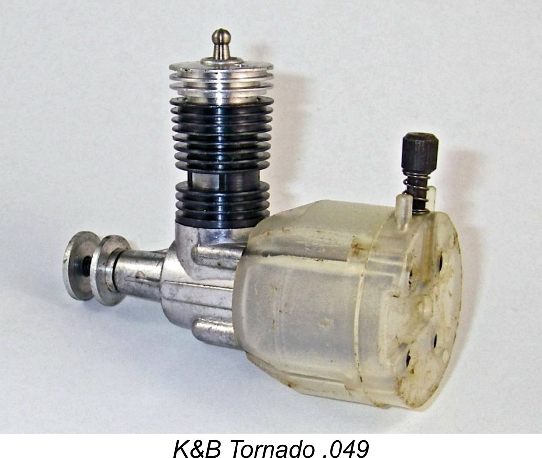 In addition, few of those Tornados that do survive ever get flown or even run these days. I consider this to be a great pity, because the Tornado is actually one of the better non-contest ½A units of its era.
 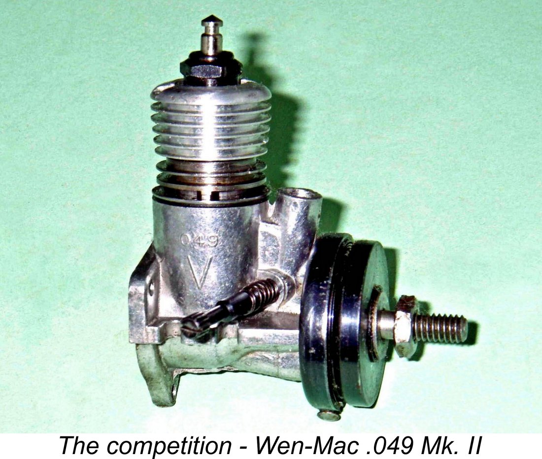 The Tornado has a rather unusual history. It began life as a contract design developed by K&B-Allyn in response to a 1958 request from the Aurora Plastics Corporation, who were then keen to become involved with the already-thriving Ready-to-Fly (RTF) model business using their own engine. They specified a certain level of performance, also stipulating that the engine had to be extremely easy to start without resorting to a spring starter.
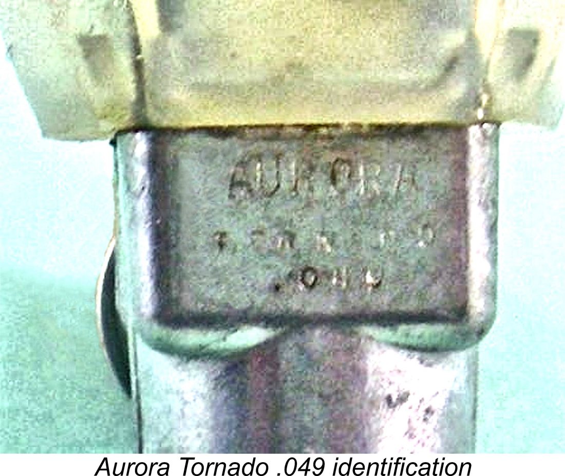 John Brodbeck of K&B-Allyn accepted Aurora’s challenge, designing what was to become the Tornado in fairly short order. The basic power unit was straightforward enough, but Aurora’s requirement for foolproof hand-starting reportedly caused Brodbeck to spend three months working on alternative induction valve designs before finally coming up with what he called the ”flex-o-valve” diaphragm induction control valve - a highly original form of reed valve, of which much more below.
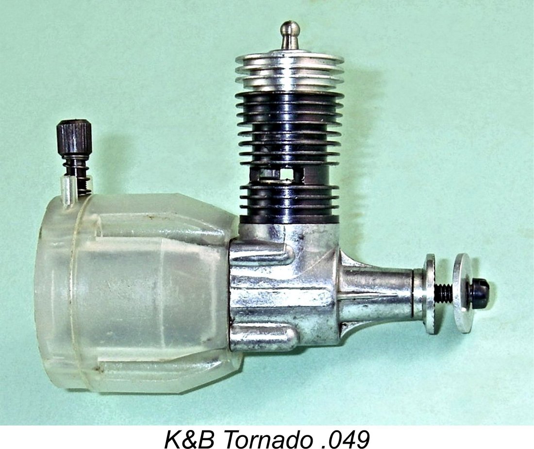
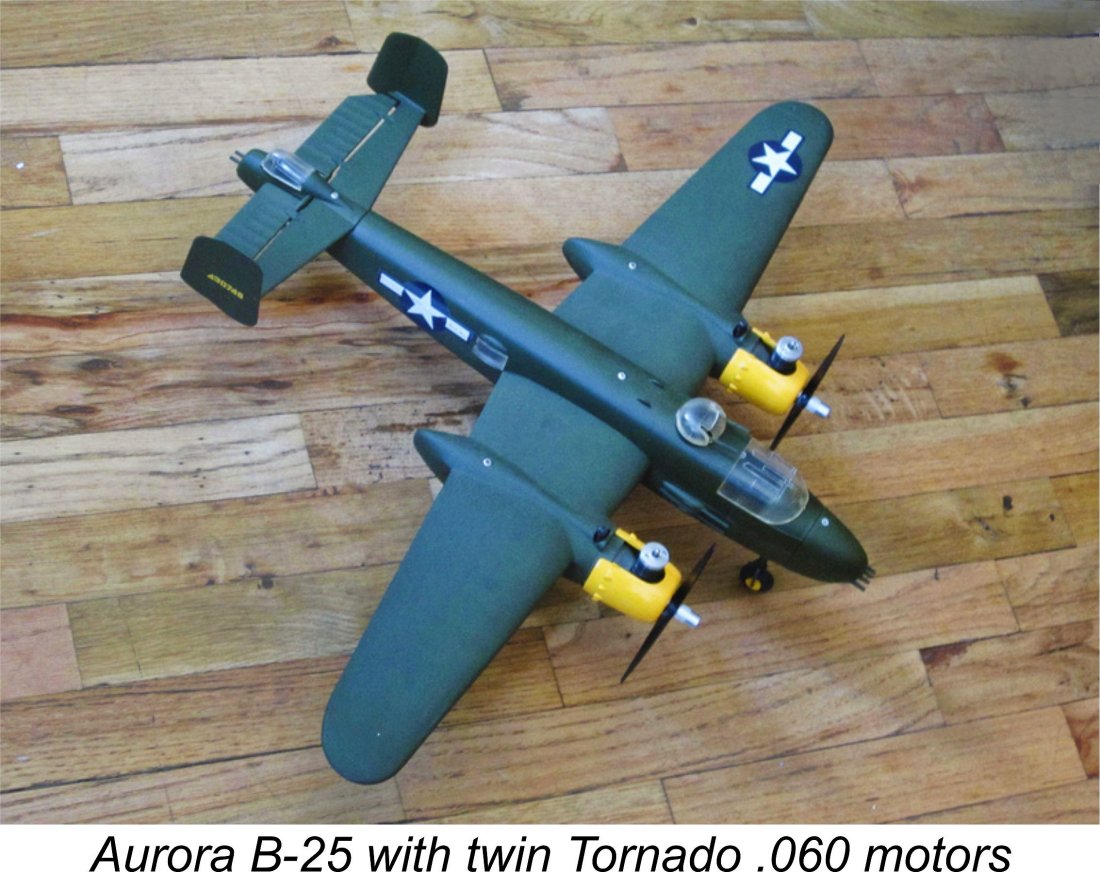
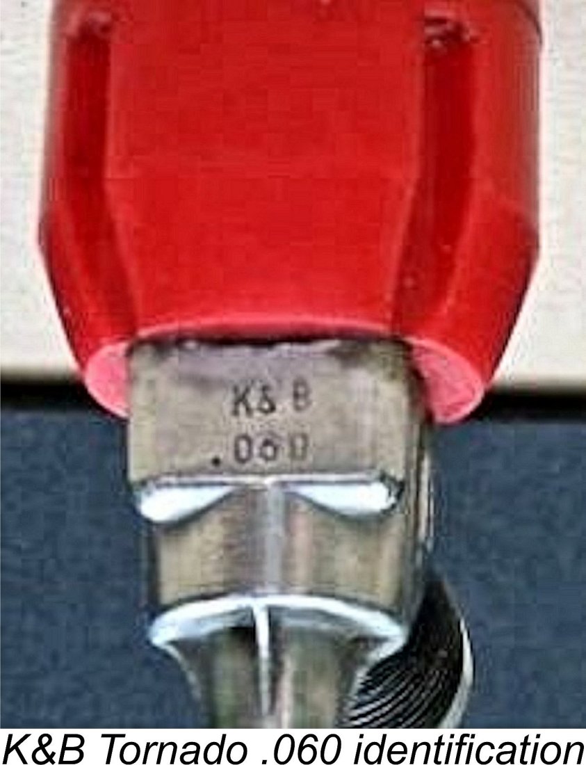 The gold-headed version of the .060 was used in Aurora’s SE-5a and Fokker D-7 RTF models among others, also being sold as a hobby engine. These .060 units were stamped K&B .060 on the
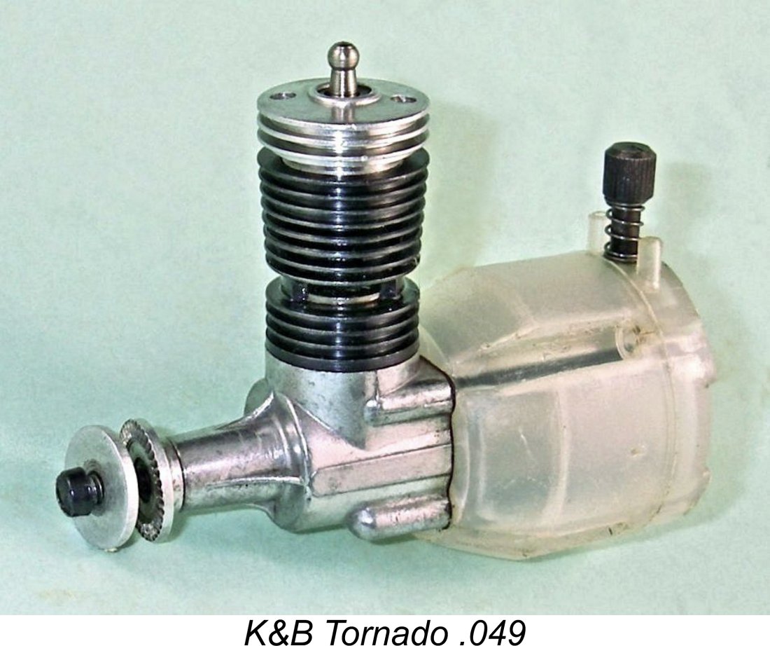
 threaded steel needle was provided with an internally threaded brass insert in which to operate, with a coil spring for tension. The brass insert incorporated the actual jet aperture with which the tapered tip of the needle engaged. The thread used was extremely fine, theoretically promoting very precise control of the mixture. Incidentally, don’t lose or damage the needle valve of one of these engines - the very similar-looking Cox equivalent doesn’t fit!
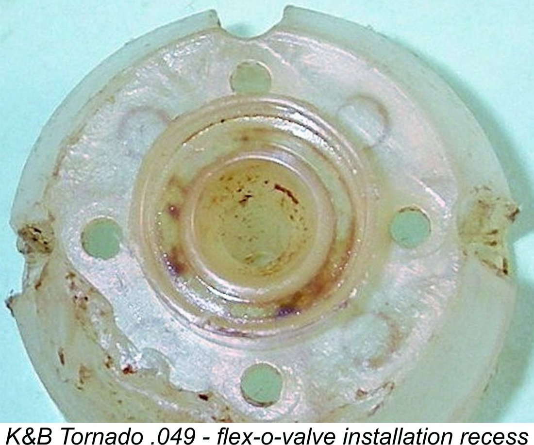
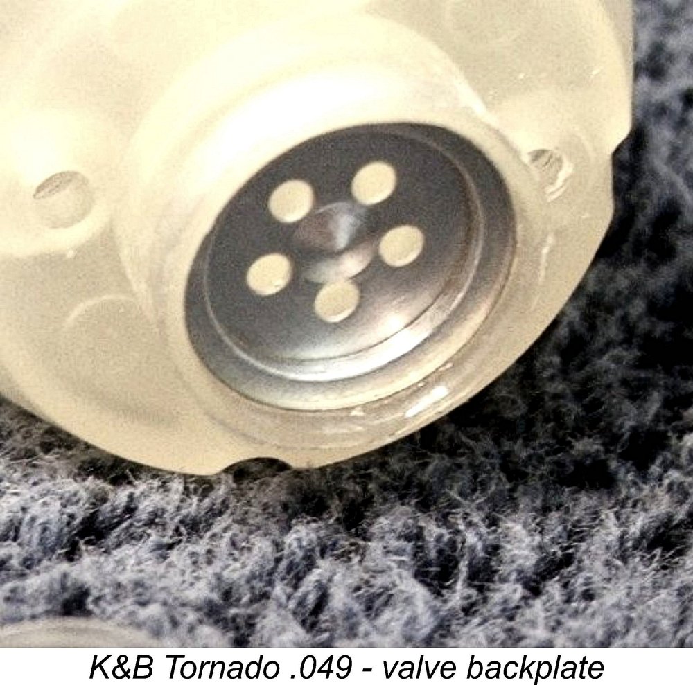
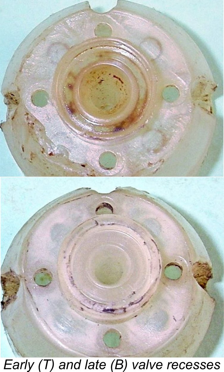
 The way in which this system works is perfectly clear. When the pressure in the crankcase falls below atmospheric as the piston rises during the induction phase, the Mylar diaphragm is drawn away from the five radially-disposed holes in the backplate and also away from the central dome. Incoming mixture is thus free to pass the valve to enter the crankcase by way of the five holes in the dish and the central hole in the diaphragm.
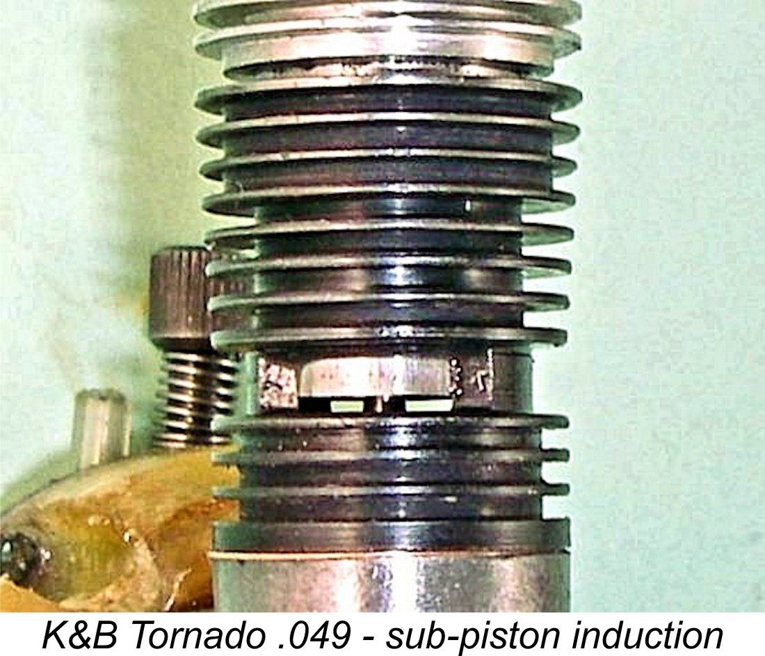
 Although the flex-o-valve evidently worked well in practise, it appears that for one reason or another the manufacturers eventually gave up on that assembly, replacing it with a conventional beryllium-copper reed along the lines of those used in the contemporary Cox reed valve models. I've found a number of references to such a variant while trolling the Internet for information on this engine.
 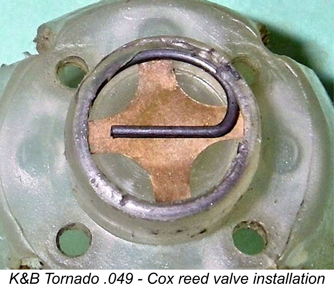 The implication is that at some point in time K&B changed the die slightly to produce Tornado tanks which were better suited to reed valve installation. This change must have been a factory initiative as opposed to an owner modification. Both .049 and .060 variants are encountered with reed valves.
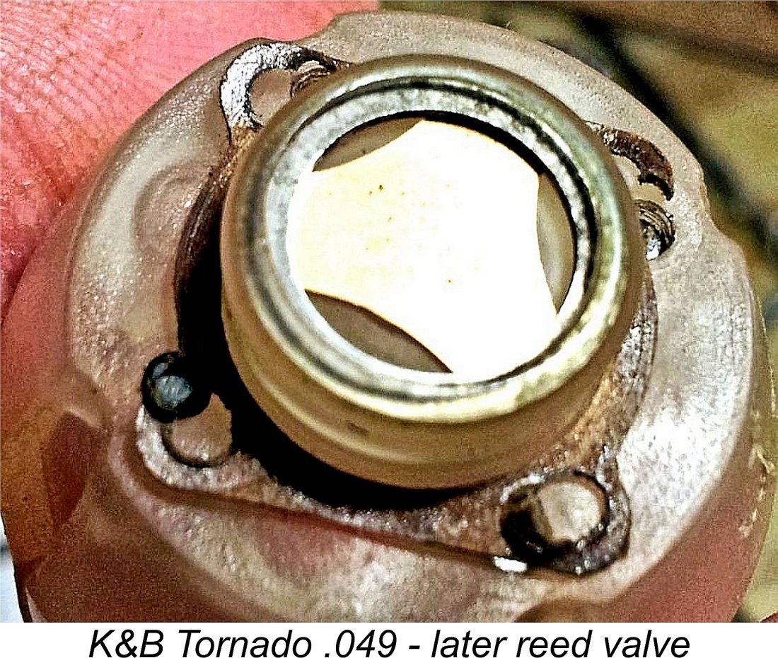
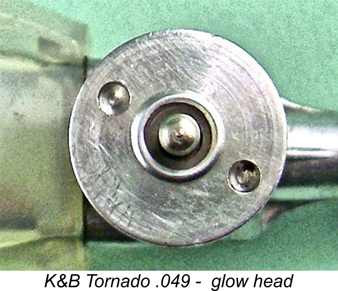 One common affliction observed on far too many examples of the Tornado .049 is a well-graunched glow-head. This component is provided with two holes having a diameter of 0.100 in. and set at a distance of 0.470 in. apart on opposite sides of a pitch circle of that diameter. A special Delrin pin spanner was available for use in removing and replacing the glow-heads. However, most latter-day owners didn't have such a tool, leading far too many of them to resort to the old vice-grip or lathe chuck method of gripping the head. Both of these methods can readily mar the head, particularly the former. If you really must use such an approach, please protect the jaws of the tool - conservation is important!
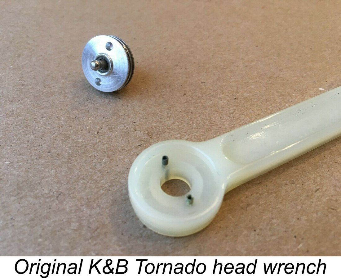 A far better approach if you have the capability is to make your own head wrench for the engine. This takes very little time - all that you need is a drill press and a suitable tap. I made mine from a spare Cox wrench which I shortened at the plug end (not essential, but it made this particular wrench instantly distinguishable from others). I then drilled two holes at a spacing of 0.470 in. with a larger 0.312 in. diameter hole centrally located between them to clear the central electrode. I tapped the two smaller holes 3 mm and took two short 3 mm cap screws which had their tip diameters reduced to
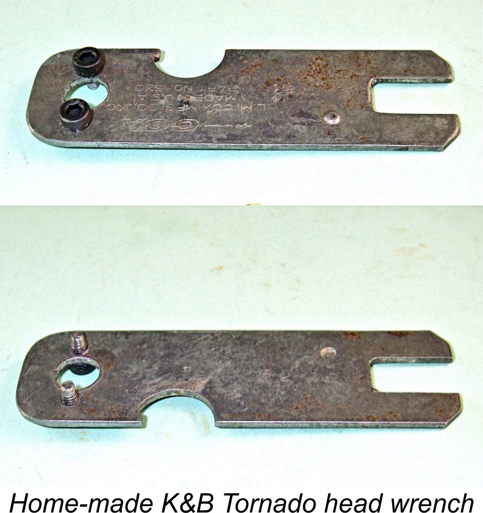
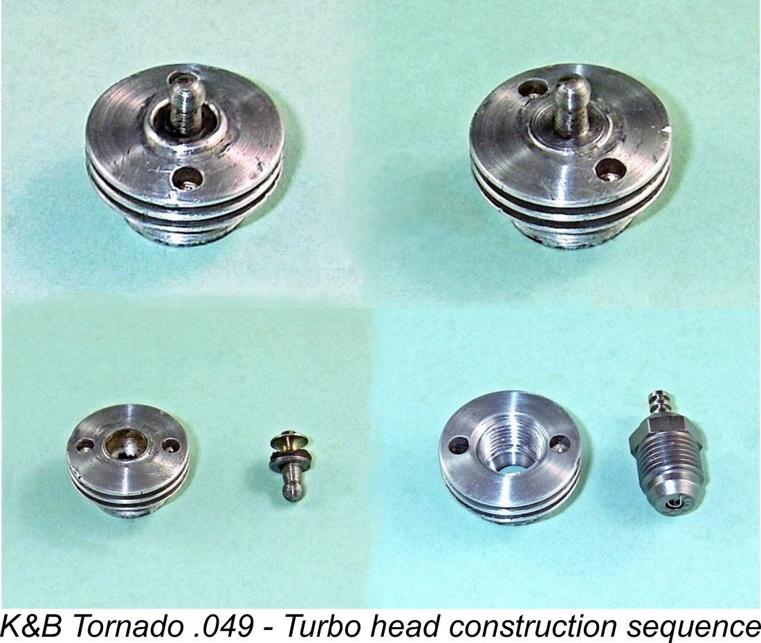
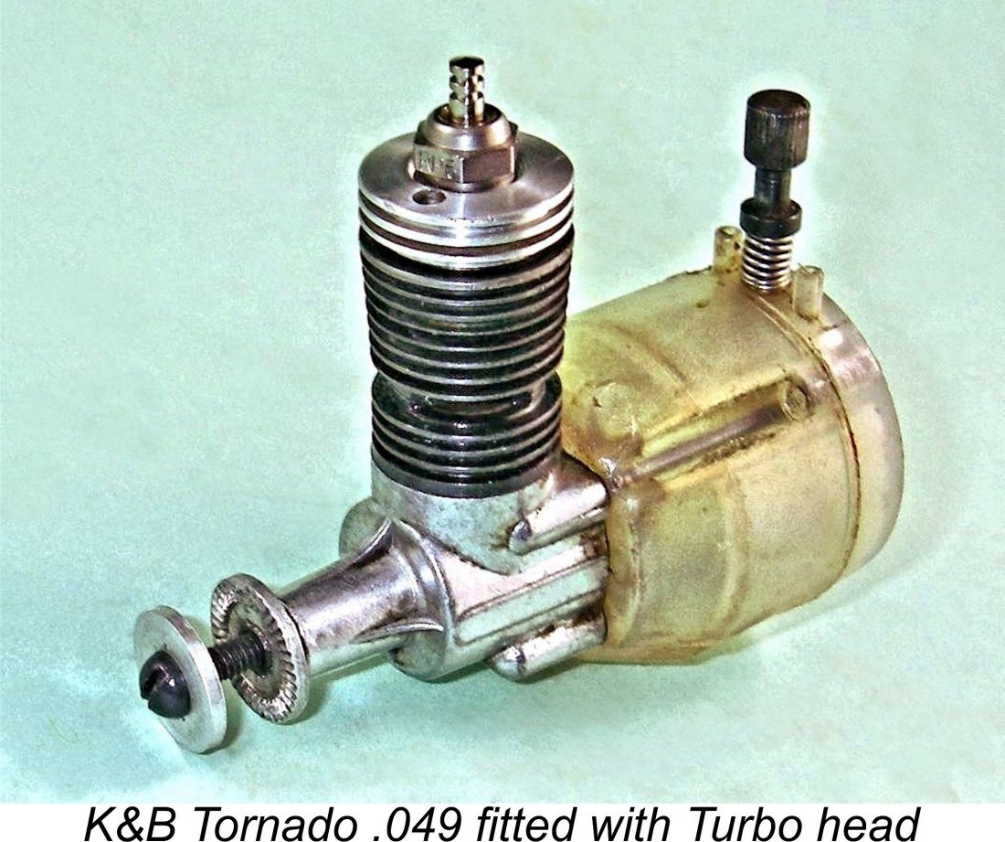 A more elegant and almost certainly more efficient option is to modify the head to accept a Turbo glow-plug. Following removal of the terminal post as described earlier, the required machining operations are straightforward enough but do require considerably more care and precision than the old ¼-32 standby. My good mate Maris Dislers has written a
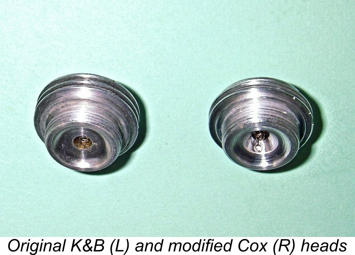
 The re-machined head requires shortening to a spigot depth of only 0.160 in. to match the corresponding dimension on the original Tornado head. Finally, machine material away around the element recess to more or less replicate the combustion chamber in the original Tornado head. Make sure that you leave the spot weld for the element untouched, and also leave a sealing surface of sufficient width around the perimeter.
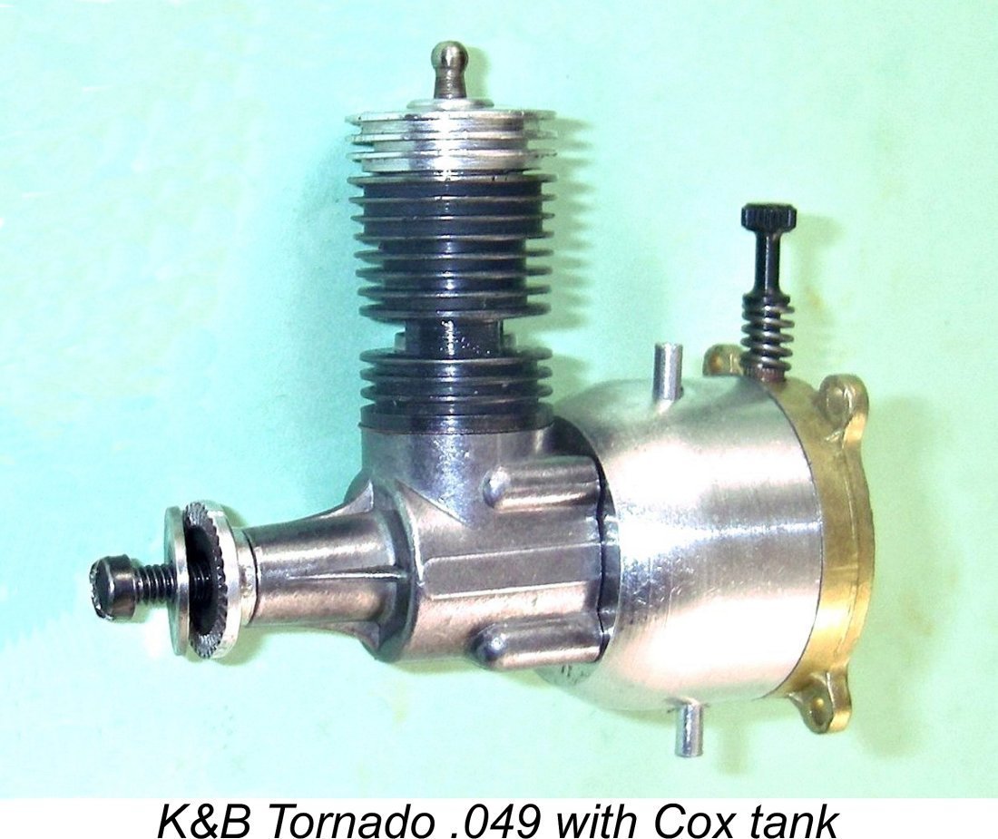 Fortuitously enough, the tank mounting holes at the rear of the Tornado are drilled to a pattern which exactly matches that of the Cox reed valve units. Moreover, the Tornado crankcase accommodates the installation spigot of the Cox reed valve tank quite comfortably. In actual fact, the Cox tank spigot is slightly undersized for the Tornado crankcase, which has to accommodate a slightly longer stroke, but this probably has minimal significance in performance terms. If one really wanted to do so, one could create a thin-walled wrap-around sleeve either by machining or by rolling some suitable shim material into a tube. Either way, the gap would be filled, thus maintaining a minimal crankcase volume.
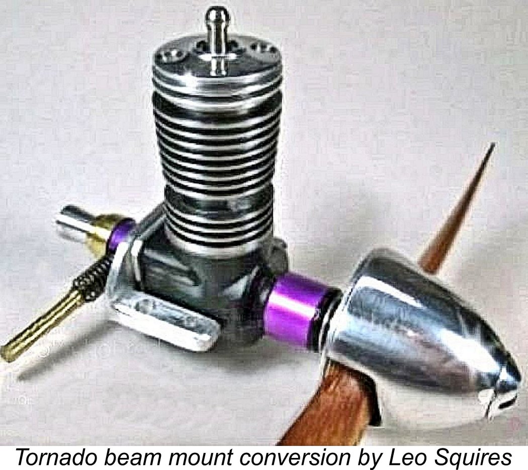
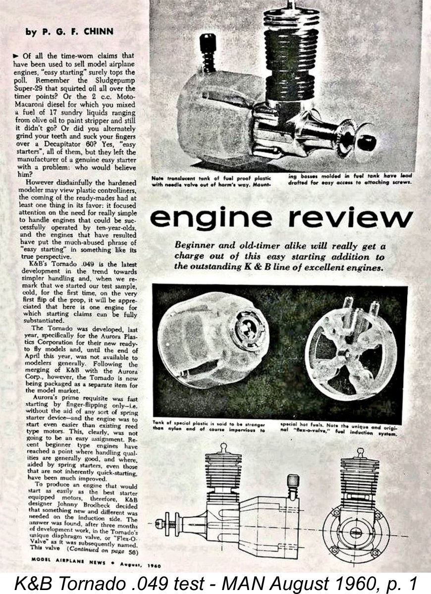 As far as I can determine, the Tornado was the subject of two published test reports. Both of these were carried out by Peter Chinn - in fact, it would appear that the same test series and resulting data were used to support both reports. The first test appeared in the August 1960 issue of “Model Airplane News” (MAN), while the second was published in the March 1961 issue of “
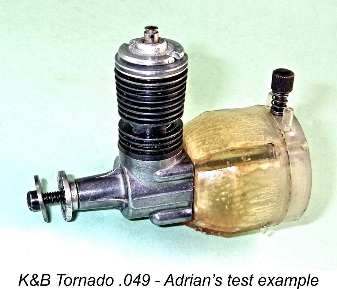 In deciding to undertake my own present-day series of tests on this engine, I had multiple objectives. Firstly, I wanted to discover the extent (if any) to which my flex-o-valve's failure to pass the suck-blow test indicated a lack of operational functionality. Secondly, I wished to compare my engine’s performance with that reported by Chinn back in the day. Thirdly, I was keen to determine whether or not my modified Cox glow-head performed at the same level as the Tornado original. Finally, I wanted to assess the effect on performance of the later switch to reed valve induction. Lots of fun to be had in achieving these objectives!
 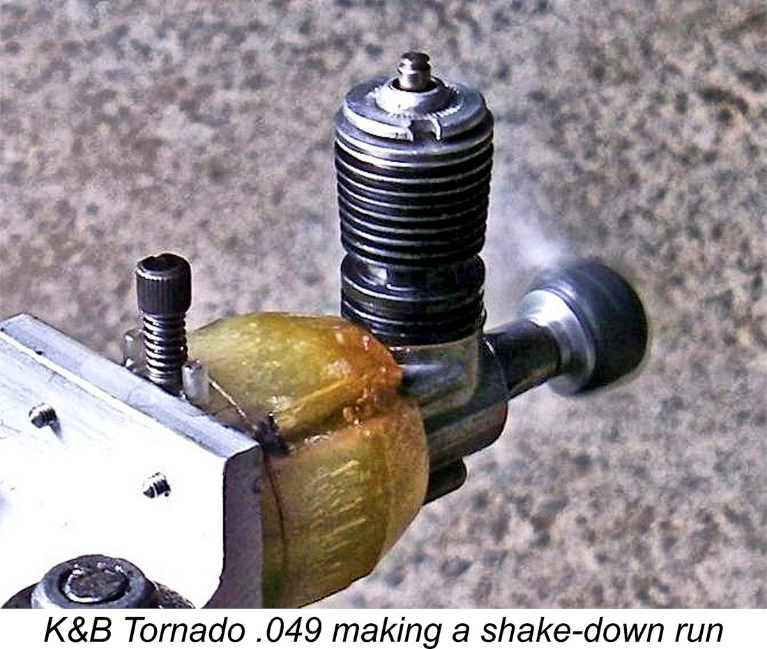 Rather to my surprise, the failure of the flex-o-valve's suck-blow test didn’t seem to have any effect whatsoever on the engine’s willingness to run! It fired up almost immediately, although I found that I had woefully under-estimated the required needle opening, causing it to rev up and then stop. Once the needle was opened sufficiently, the engine started right up again and kept running steadily, waiting for me to set the needle to the optimum position.
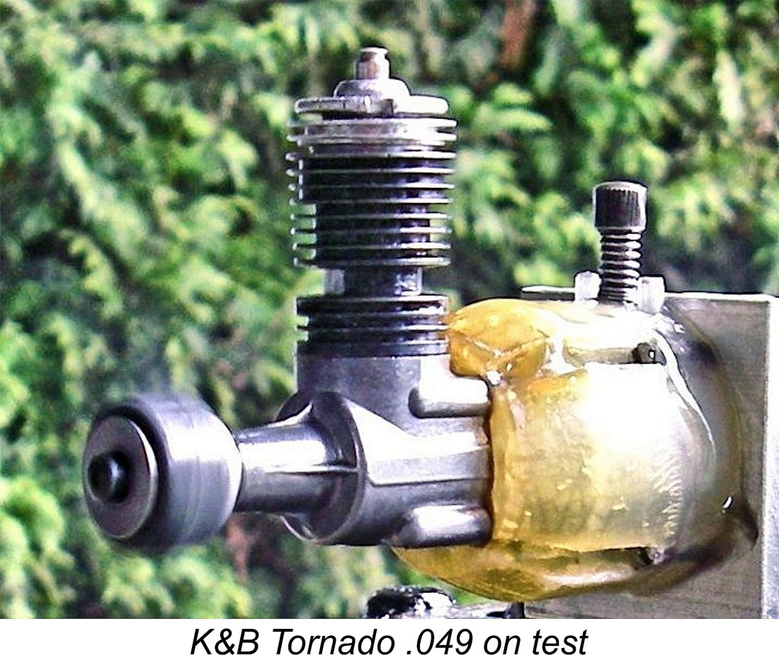 Returning to the test of the Tornado, once its operating characteristics had been recognized, zeroing in on an optimum setting was perfectly straightforward. The very fine thread used for the needle was very helpful in establishing the precise sweet spot - although well-defined, the setting was by no means excessively critical. Once set, running was absolutely smooth and steady, with no trace of a misfire. Moreover, the engine remained extremely easy to start at all times.
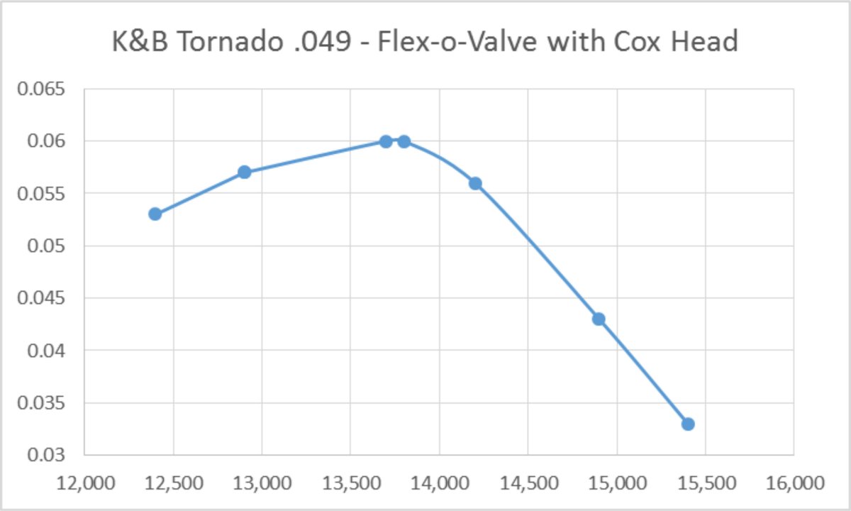
 Still not yet having had anywhere near enough fun, I removed the tank with its flex-o-valve and replaced it with the tank which came with the incomplete unit kindly supplied by Maris Dislers. The reader will recall that this tank was fitted with a Cox reed valve assembly which was a perfect match. I thought that it would be interesting to see how well the Tornado performed with this very different induction valve. Since the actual power unit was the same in both tests, any differences would necessarily be down to the valve.
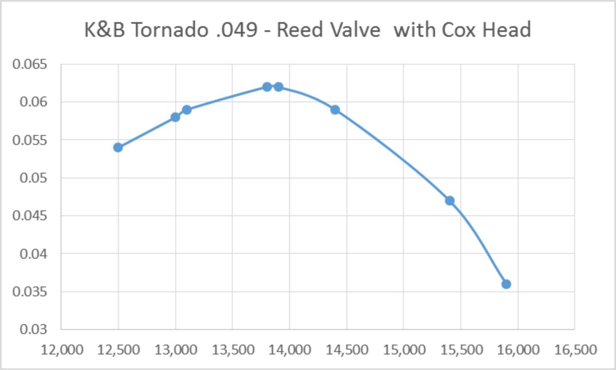
 The main limitation that I can see which would have militated against the engine's widespread use as a hobby powerplant was the tank. The Tornado's construction was such that one was pretty well forced to use the tank as supplied, since it formed an integral component of the mounting and carburetion arrangements. Although it was sufficiently translucent to permit observation of the fuel level prior to launch, the tank was far larger than required for free flight applications. Moveover, it was not appropriately vented for aerobatic control ine use.
 | |