
|
|
California Curiosities - the APEX Engines
Although the APEX engines themselves have been quite well documented in the past, they have never been securely dated, nor has anything of note been recorded about the company that manufactured them. All that seems to be known for sure is that the manufacturers listed themselves as APEX Motors, P.O. Box 443, Berkeley, California. We don’t even know where in Berkeley the manufacturing of the APEX range took place, nor do we know the names of any of the individuals responsible. All that seems to be generally accepted is the fact that production was confined to a relatively short period in the mid 1930’s at a time when commercial model engine manufacture in the USA was just beginning to get into its stride. There's little doubt that this was one of America's pioneering model engine ranges. As always when writing about an American model engine series, my first move was to contact my late and much-missed friend and mentor Tim Dannels, publisher of the “Engine Collector’s Journal” (ECJ) and author of the “American Model Engine Encyclopedia” (AMEE). Most unusually for an American marque, Tim acknowledged the fact that he had very little knowledge of the APEX range beyond the brief descriptions of the various APEX models which appear in Volume 2 of AMEE. A very short write-up appeared in issue 161 of ECJ, but that didn’t yield any information on the company itself.
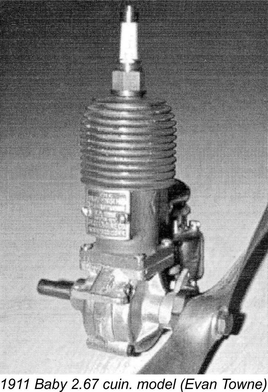
Despite working with the APEX engines for over 40 years now, Don was forced to concede the fact that he has never come across any information on either the history of the company which made the engines or the personalities involved. However, he was able to provide some very useful information about the engines themselves. Another source of information on the APEX range comes from the surviving writings of a now-deceased gentleman name Don Stroot, a long-time collector, model engine builder and MECA member from California who somehow acquired the residue of the APEX project during the 1960's. Fortunately for us, Don wrote up a quite detailed technical description of each APEX model based on the materials which he acquired. He also appears to have been the principal source of the original castings upon which the patterns for later reproductions have been based. Unfortunately, Don was not able to add anything to our knowledge of the APEX Motors company itself, nor was he able to clarify the dating issue. Given the above situation, about all that can be done to shed some light on the genesis of the APEX range is to consider it in the context of its time and place. I’ll attempt to do that in the next two sections of this article. Context By far the best record of which I’m aware which covers the early history of model engine development in the USA is the article by the late Bill Mohrbacher (then MECA President) which appeared in the February 2012 issue of “Model Aviation”. This highly recommended article may be accessed on line through this link. The development of internal combustion engines suitable for models goes back way further than many people realize. Indeed, it closely followed on the heels of the development of full-sized internal combustion engines, which were also still in their relative infancy during the final decade of the 19th century. Not surprisingly, the earliest miniature engines were individually hand-built curiosities as opposed to commercial productions. Some of them represented remarkable model engineering achievements. In contradiction to their “miniature” characterization, these early model engines tended to be massive affairs which were better suited for powering model boats than airplanes. However, during the first decade of the 20th Century a number of During the first decade of the 20th century, development proceeded quite rapidly, to the point that by the end of the decade model engines had begun to appear on a commercial basis in various countries. As early as 1909, the famous Gamages department store in England was advertising a small single-cylinder 2-stroke engine of undefined displacement which was suitable for models. The attached image is copied directly from their 1909 catalogue. This may have been the very first model I/C engine to be offered commercially. It appears to have had a float carburettor. From his location in Manchester, England, the previously-mentioned W. G. Jopson began to market his opposed twin-cylinder four-stroke design in 1910. In 1911 Radiguet & Massiot of France introduced an opposed twin-cylinder two-stroke engine of 16 cc displacement which was specifically intended for model aircraft use. They were soon joined by the Galiment company, who introduced a series of one, two and It appears that the first model engine to be produced commercially in the USA was the Baby two-stroke unit of 1911 which was manufactured initially by the Baby Engine Co. of Stamford, Connecticut and from 1913 onwards by the Weiss Manufacturing Co. of Torrington, Connecticut. In defiance of its name, this was a massive engine having a 2.67 cuin. (43.75 cc) displacement and weighing all of 3¾ pounds (1.7 kg.) with its 18 inch diameter 13 inch pitch aluminum propeller and gas tank. The Baby was also available in inline two and four cylinder configurations. The Weiss Manufacturing Co. continued production of the Baby through to 1929. The engine’s acceptance by the modelling community prompted the development of other competing designs such as the 1.18 cuin. (19.34 cc) Gil Aero Midget of 1922. However, model engine manufacturing had yet to become a major industry. Moreover, so-called "miniature" engines were still pretty big, discouraging their adoption by everyday model fliers given the size of the models required to accommodate them. In 1931, the trend towards downsizing of model engines commenced with the appearance of the Knight 0.451 cuin. (7.39 cc) model from Chicago. During the same year, Weiss designed an even smaller .331 cuin. (5.42 cc) engine to supplant the now discontinued Baby. Weiss sold only plans for the .331, leaving it to Louis Loutrel of New York to sell assembled engines as well as kits including the plans, castings and materials. Walter Hurleman of Philadelphia was another individual who entered the model engine manufacturing field at this time. He did so in 1933 with his .604 cuin. (9.90 cc) "Aristocrat" model, which remained in periodic production in various forms right up to America's entry into WW2. In 1934 Louis Loutrel took over the Weiss engine design outright, redesigning it to eliminate the rear timer and raising the displacement from .331 to .517 cuin. (8.47 cc). He sold the redesigned unit under his own name. As history shows, the highly regarded Loutrel engine was later transformed by others into the infamous G.H.Q., of which much more elsewhere.
The resulting demand for the Brown engines prompted Bill’s dad and another investor to form the Junior Motors company in Philadelphia. In 1934 this company introduced the Brown Junior model B, selling more than 5,000 engines in the first two years. Gas powered models had come of age, and the commercial model engine market was now open for business! This naturally encouraged other gifted model engineers across the country to get to work on competing designs during 1934 and beyond. More new commercial models soon appeared to challenge the Brown design. These included the 1934 Tlush Super Ace .601 cuin. offering, the .99 cuin. Forster Model “A” of 1935, Dan Calkin’s diminutive 1935 Elf “Corncob” .138 cuin. model (for which he had to make his own special miniature spark plugs), the .364 cuin. Baby Cyclone of 1935 and the Ohlsson Miniature .56 cuin. model of 1936. The unknown designers and constructors of the APEX engines which form our main subject were another group which made a relatively early entry into the highly competitive model engine marketplace which was evolving in America at this time. But before we commence our look at the designs with which they challenged the emerging market, we need to address the dating issue. The Dating Question When considering this matter in connection with any American model engine range, my invariable first port of call is AMEE. Volume 2 gives 1936 as the date for all APEX models listed apart from the various reproductions. In response to my request for clarification, author Tim Dannels advised that this date was assigned for no better reason than the fact that it has apparently become enshrined in the folklore of model engine history, having been “handed down” for decades with no supporting evidence of which Tim is aware.
The terms of these advertisements seem to imply that they were then trying to liquidate unsold stocks of the Skylark 53 model (see below) - there’s no mention of any of their other known designs. The fact that they took the classified ad route implies that they weren’t trying very hard - perhaps on the point of giving up! Neither I nor my colleagues have been able to locate any more prominent advertisements for the APEX engines. Interestingly enough, the company described itself in these classified advertisements as APEX Motors, 443 Berkeley, California - the fact that the 443 was their P.O. box number was not specifically clarified. How inquiries were supposed to reach them is anyone’s guess! Perhaps there was a convention at the time that such a number was always interpreted as a P.O. box number. Now let’s consider another important piece of evidence. If the 1936 introductory date is correct for all models, one would surely expect at least one or two of the engines to still be listed as of 1937 unless all four models came and went in less than a year, which seems highly unlikely to me. In fact, they’re not listed - most persuasively, none of the APEX models are included in the otherwise quite comprehensive article by Carl Schmaedig entitled “Design Data for Gas Modellers” which appeared in the July 1937 issue of “Model Craftsman” magazine. This article surveyed the American model engines which were then available, including a few relative obscurities like the Tlush and Aero Precision offerings.
Despite this, the APEX engines are conspicuous by their complete absence. We know from the previously-cited classified advertisement that the company was still in existence as of mid to late 1936. However, if the APEX engines were all actually introduced in that year, I would have expected at least one or two of them to appear in the mid 1937 survey. To me, this implies that they had actually appeared considerably earlier than 1936 and had already disappeared by early to mid 1937.
Based upon my many studies of various model engine manufacturing ventures, I feel quite confident in asserting that the development and testing of four distinct models showing progressive design improvements, together with the creation of the required patterns, jigs and tooling, would take two years at the very least. This suggests that if the APEX engines had already disappeared by early 1937, they must have made their initial appearance in 1934 or early 1935 at the latest. The architecture of the Skylark in particular is completely consistent with such an early date. Even by 1936 standards, it looks retro to the max! In this regard, I believe that some further conclusions may legitimately be drawn from an objective review of the chronological order in which their architecture suggests that the various known APEX models appeared. To me, the Skylark and Marine 53 models with their relatively “primitive” brazed-up cylinders and intake tubes look like the Some support for this view is to be found in Don Stroot's well-informed technical description of the APEX 120. In that write-up, Don clearly stated his opinion that the 120 followed the “earlier” Skylark, citing its “far superior” quality and appearance. Having got this far in following this scenario, we then have to consider the fact that the APEX 120 (which I believe to be the second APEX model to appear) bears a resemblance to the Forster 99 Model “A” of 1935 which is surely more than coincidental. There are certainly some differences, very much including the displacement, but the conclusion that one model directly influenced the overall design of the other is inescapable. The crankcase configuration of the APEX 120 appears to be a clear reflection of the design of what I believe to be the earlier Skylark 53 design as opposed to a copy of any design by others. Apart from its size, it's more or less identical to that of the Skylark. For this reason, I believe that the APEX 120 is far more logically seen as a design progression from the earlier Skylark 53 than as an imitation of the Forster 99. The Forster brothers did not have an earlier design of their own to build upon - APEX Motors did.
The Forster 99 Model “A” was released in 1935. If that design was in fact influenced by the APEX 120, then it follows that the APEX 120 must have been in existence by early 1935 for it to have been available for the Forster brothers to copy. This is entirely consistent with the scenario of a 1934 release of the Skylark 53 and the subsequent development of the APEX 120. OK, so we seem to have established a strong possibility (but by no means a certainty) that the APEX 120 was actually released in early 1935. The APEX 45 is even more advanced than the 120 – while retaining many of the design features of the 120, it now has a one-piece crankcase with no split, suggesting a further progression from the 120 design. This suggests that it followed both the APEX 120 and the Skylark. Assuming a 1934 release date for the Skylark and an early 1935 date for the 120, the 1936 date assigned to the APEX 45 in AMEE thus appears entirely credible as far as I’m concerned.
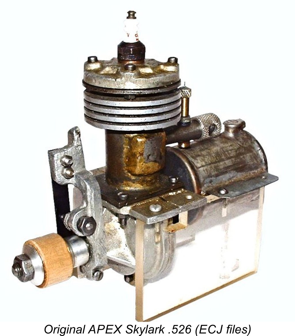
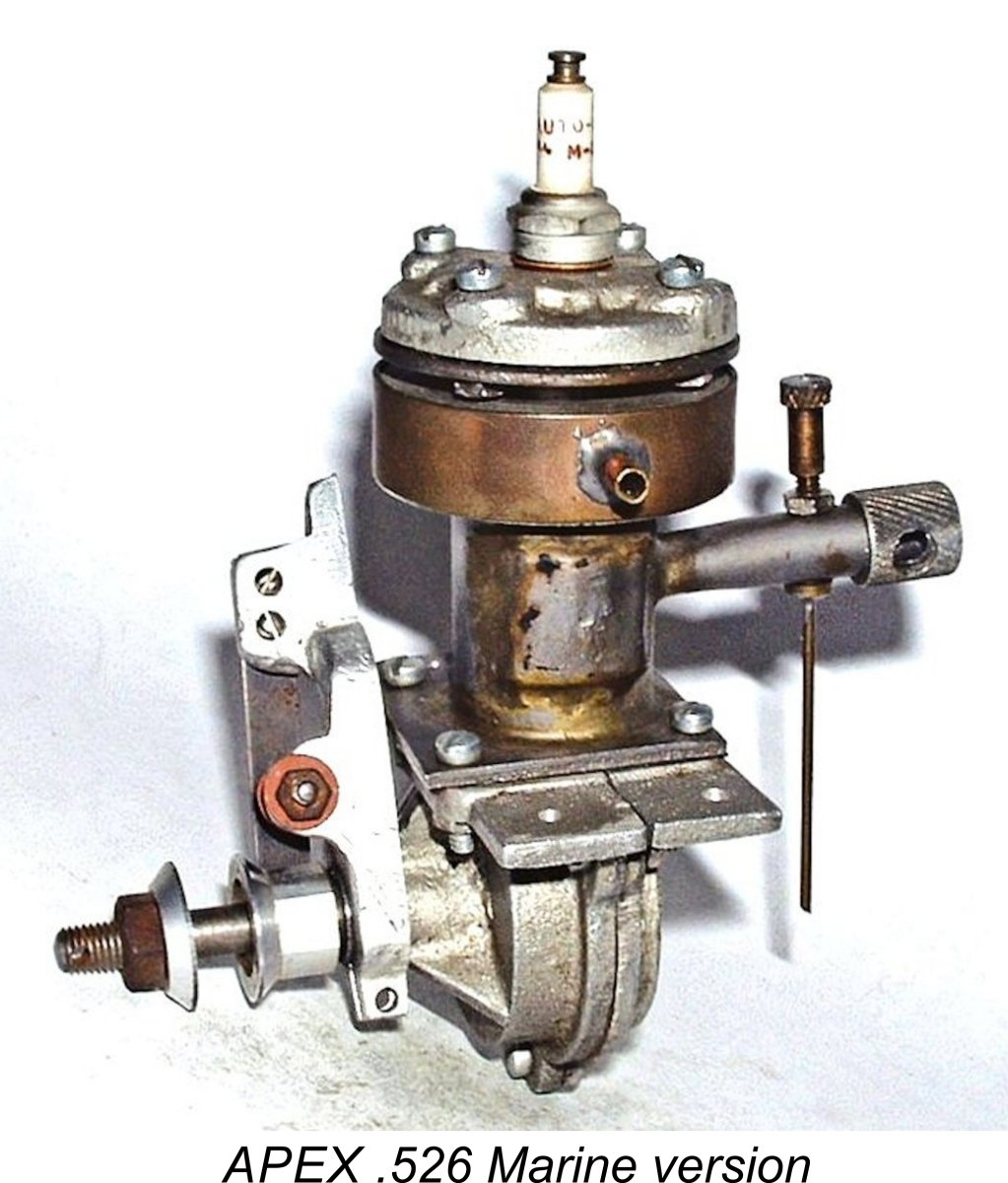
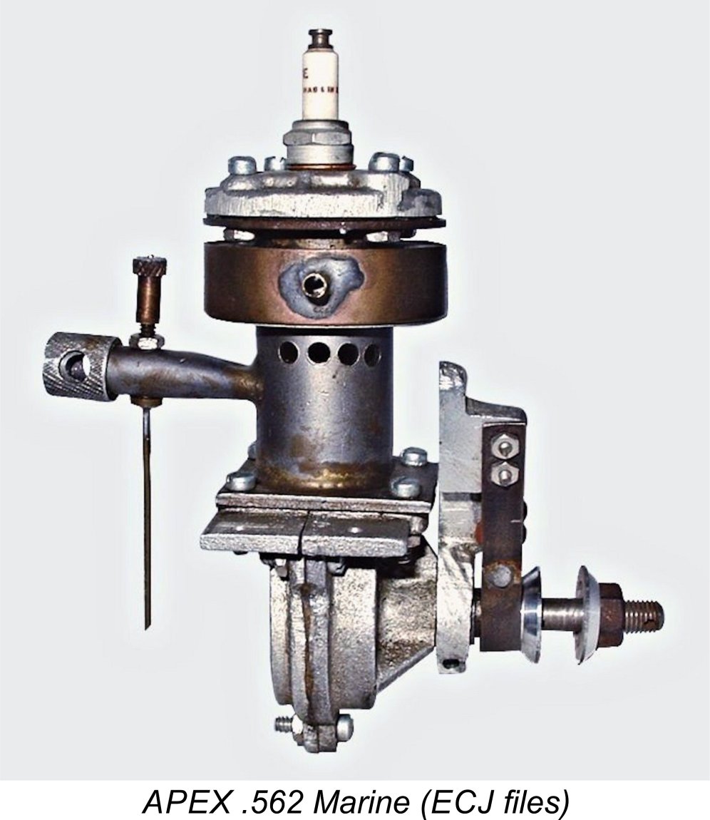
In the end, we have only Don Stroot's comments, the late 1936 classified ads, the engines’ non-appearance in that July 1937 article and their comparative architectural characteristics to go on. Taking that evidence as a whole, I consider it to be more likely than not that the first APEX engines (the 53 Skylark and Marine) were actually released in 1934 and that the marque had already gone out of production by early 1937. Certainly, I can find no evidence of their ongoing existence in any references published beyond that October1936 classified ad in MAN. Pending the rather unlikely appearance of further authoritative information, we’ll have to leave this discussion in this rather unsatisfactory state. Meanwhile, we can step onto firmer ground by taking a look at the various models offered by APEX Motors. I’ll do so in the order in which I believe the successive designs most likely appeared. The APEX 53 ”Skylark” and “Marine” Models As stated earlier, it appears to me to be very likely that the first designs produced by the company were its .526 cuin. “Skylark” aero unit along with its “Marine” model boat counterpart of identical displacement. I also believe that these units most likely appeared in 1934 or just possibly early 1935. I base this opinion on the fact that both the design and construction of these models are considerably more “primitive” than those of what I believe to be the later APEX models. Unless and until someone presents authoritative evidence to the contrary, I will continue to advance this opinion.
The accompanying component view from the instruction manual should clarify the Skylark’s main structural features. The engines were built up around a sand-cast crankcase which was vertically split at right angles to the engine’s axis. Three bolts with nuts were used to secure this assembly. The cylinder was a steel sleeve having both the intake venturi and the bypass brazed on. Gas access to the bypass from the crankcase was secured using two holes through the cylinder wall at the bottom of the bypass which aligned at bottom dead centre with a matching pair of piston skirt ports on the bypass side. The aluminium alloy cooling jacket with its machined cooling fins was pressed or shrunk on prior to the brazing of the topmost cylinder flange. Obviously, final bore finishing had to be carried out after this assembly was complete. Rather a time-consuming production challenge, one would think! The engine used a separate cast alloy cylinder head which was attached with four screws. Somewhat unusually, these screws engaged with four nuts located below the brazed-on top flange, creating a somewhat "fiddly" assembly challenge. The completed cylinder assembly was located on a shelf formed at the top of the crankcase, to which it was attached by four more screw-and-nut combinations. Although the standard model featured a cast light alloy piston with a single cast iron ring, surviving components examined by Don Stroot suggested that the option existed to use a lapped steel piston with brazed-on baffle and wrist pin bosses. The Don Sohn reproduction splits the difference, using a single-ringed cast iron piston with integrally-machined baffle and bosses.
The crankshaft was built up from no fewer than four separate components. The 5/16 in. dia. main journal was of steel, while the counterbalanced crankweb was made from aluminium alloy. The crankweb was secured to the main journal using a pressed-in fine-angled tapered steel pin which acted as a wedge against a suitable channel cut into the main journal surface. Finally, the steel crankpin was pressed into the alloy crankweb. Seems a little dodgy to me, but perhaps it was up to the job in this relatively low-speed engine. Don Sohn used this same composite construction when creating his reproductions. It must be said that this assembly appears to represent a potentially significant design flaw. Unless the tapered pin is an extremely accurate fit in its location hole and bears really tightly against the main journal with absolutely zero play even under stress, the interlocking between the crankweb and main journal is almost guaranteed to work loose over time. Any slight play that may develop needs to be taken up at once by driving the pin further in using a suitable riveting drift and a small hammer. On top of this, the crankweb has to be a super-close interference fit on the main journal if things are to remain tight. In addition, the crankpin has to be a mega-tight press fit if it is to remain secure. Overall, the required level of precision would make the construction of this crankshaft a real challenge for the average home builder. Frankly, I'd rather tackle a conventional one-piece steel shaft! The well-braced but rather short main bearing was cast integrally with the front half of the vertically split crankcase. The 5/16 in. dia. main crankshaft journal was supported by a pressed-in bronze bushing. At The “banjo” style timer used a cast alloy frame which accommodated a flat spring to which the moving point was soldered. The spring has a relatively low tension, implying that the engine was not expected to operate at high speed. The dwell period (the extent of crankshaft angle during which the points are closed and current is flowing to the coil) is very short - only around 25 degrees or so. This is a very marginal figure which again does not create any expectation of high operating speeds The tank was of unmistakably early pattern. It was a completely separate component consisting of a thin tinplate steel cylinder with soldered-on ends and a Gits filler cap at one end. A plain hole at the opposite end provided access for the extended brass fuel pickup line which was soldered to the spraybar. The tank was provided with flanges to allow it to be mounted on the same beam mounting bearers used for the engine itself. The APEX Skylark was clearly aimed at the hands-on home constructor as much as the model flying community. The instruction manual stated that the engine was available in three distinct versions, as follows:
Both kits included a full set of instructions and working drawings together with all necessary materials including nuts, bolts and gaskets. The $5.75 kit included a finished cylinder assembly along with a finished wrist pin, piston ring and timer spring together with ignition components (including the spark plug) and suitable fuel line material. The $5.00 kit was far more of a challenge since one had to complete the brazing of the cylinder assembly and then machine and lap the bore to its final dimensions and finish.
In terms of its operation, the manufacturers recommended a fuel consisting of six parts of gasoline to only one part of SAE 70 oil - an unusually low-lubricant mixture at just over 14% oil. Sounds like a latter-day team race mix! I would be tempted to use a fair bit more oil myself. The suggested points gap was 0.010 in. Rated output was claimed to be 0.200 BHP @ 5,000 rpm. No propeller size was specified, but the engine was said to operate at between 4,000 and 5,000 rpm. These performance figures are certainly suggestive of an early date for the design. As stated previously, I believe it to be more probable than not that this model and its marine counterpart were introduced in 1934. The plain fact is that this rather "agricultural" design would have become out-dated very rapidly by comparison with other emerging designs from 1934 onwards. By 1936 it would have appeared positively prehistoric! Moreover, experience with this unit appears to have revealed some areas in which the basic APEX design could be improved. At the same time, a decision seems to have been taken that a significantly larger and hence more powerful unit would attract more customers. This evidently led to the appearance of the next APEX design to materialize - the massive APEX 120. The APEX 120
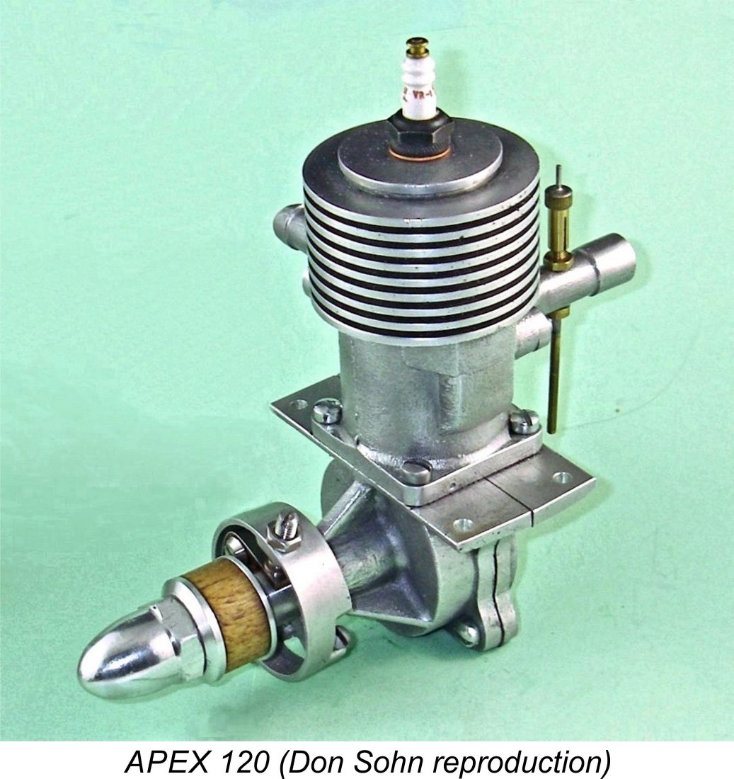
Bore and stroke of the APEX 120 were a nominal 13/16 in. (30.16 mm) and 11/16 in. (26.99 mm) respectively for a nominal displacement of 1.177 cuin. (19.28 cc). My illustrated Don Sohn reproduction of this engine weighs in at a hefty 17.95 ounces (509 gm) with plug but minus tank and ignition support system. Perhaps the most awkward feature of the Skylark 53 from a production standpoint had been the complex composite construction of the cylinder unit. The required brazing would have involved the use of jigs to hold everything together during the brazing process. Moreover, the fitting of the aluminium alloy cooling jacket and the subsequent brazing of the top flange would have been a tricky process to get right. It was presumably for these reasons that when designing the larger APEX 120, the designer elected to replace the brazed-up composite cylinder component with a far more easily The finished casting accommodated a steel cylinder liner which was pressed or shrunk in from below. As with the Skylark, the bypass was supplied with mixture by way of a pair of piston skirt ports which aligned with holes opening into the lower bypass through the cylinder wall. The exhaust stack and intake tube were both secured by two screws apiece. As before, the upper cylinder assembly was secured to the crankcase with four screws. The Skylark's crankcase design was reproduced almost exactly for the 120 apart from the larger size, with the crankcase being vertically split once again at right angles to the engine’s axis. Four screws were now used to hold the two crankcase halves together. Don Stroot commented that the quality of the original 120 castings was noticeably superior to that seen in the earlier Skylark model. Evidently APEX were learning on the job ..........
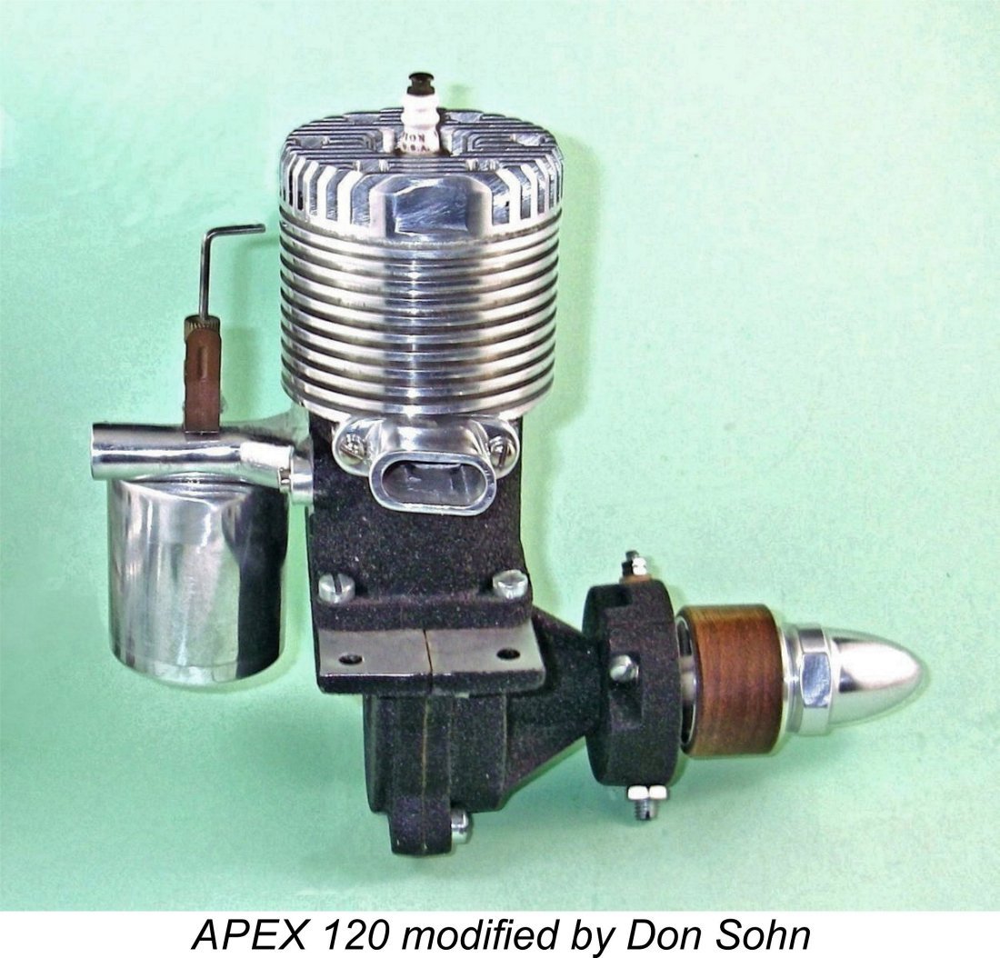
The crankshaft was again of composite construction, but this time using only three components. The crankweb was now of steel and was welded to the steel main journal. The tubular steel crankpin was once again pressed into the crankweb. It appears that the designers may have recognized the inherent weakness of the Skylark's bi-metallic pinned crankshaft design discussed earlier. The shaft ran as before in a bronze bushing. At the front, the timer was now of the semi-enclosed type using automotive-style points inside a cylindrical frame. The cam continued to be made from aluminium alloy, being aligned with the shaft once more using a Woodruff key. The tank supplied with this engine was of identical pattern to that associated with the earlier Skylark, being intended to be mounted on the engine bearers as before. Reportedly a marine version of the 120 was also on offer, although I do not have an image of that variant to share. Both Don Stroot and Don Sohn made reproductions of It’s worth noting at this point that Don Sohn also made 4 examples of the APEX 120 that were modified in a few respects. Don tells me that this modified version was based upon a photo of a far earlier unit which was published back in the day in an early issue of “Model Airplane News”. Among other tweaks, Don’s rendition features a detachable cylinder head and an integral hang tank along with a black crinkle paint finish on the crankcase. Weight of this variant with tank is up significantly to 21.45 ounces (608 gm). As discussed earlier, there seems to be a strong possibility that APEX Motors raised a little working capital by selling the APEX 120 design to the Forster brothers in mid 1935. If so, the number of original examples of this engine that were made by APEX must have been very small. The original engine's extreme present-day rarity certainly supports this notion - most examples encountered today are reproductions. Those made by Don Sohn are of outstanding quality. Regardless of the truth of this matter, it would appear that the development of the APEX 120 soon had the manufacturers thinking about a further addition to the range which would represent yet another step forward in terms of design. The result was what was to prove to be the final model to appear under the APEX name - the APEX 45. The APEX 45 For no good reason that I can discern, this engine has generally been referred to as the APEX 44, although in reality it's undoubtedly a 45! Since there's no evidence whatsoever that the manufacturer ever applied the APEX 44 name to the engine, I've chosen to go with the engine's actual nominal displacement. It's never too late to correct previous inaccuracies! My friend Tim Dannels has expressed some reservations concerning the identification of this model as an APEX product. It does certainly display some key design departures from earlier APEX models, but there are more than enough carried-over features to make the identification seem perfectly credible. Our most persuasive witness is once again the late Don Stroot, who found components of this model in the assemblage of material which represented the residue of the APEX venture. Don's witness plus certain other features suggestive of an APEX origin are good enough for me unless someone can present authoritative evidence to upset the identification.
Until 1934, only large automotive-type spark plugs such as the 5/8 inch Rajah and the 12 mm Bosch plugs were available. These plugs were too large for the smaller displacement model engines, in effect limiting the lower end of the practicable displacement range for model engine designers unless they were willing to follow Dan Calkin’s lead by making their own miniature spark plugs. Look at the size of the Rajah plug installed in the previously-illustrated original Brown .60 of 1931! This situation prompted both Junior Motors and Hurleman to commence the production of their own 3/8 inch spark plugs in 1934, with both Blintliff and M&M quickly following suit. Such plugs were thus becoming more readily available by the time that the APEX Skylark entered production. The APEX engines were all constructed to accommodate 3/8 inch plugs. In 1936, AC began producing 3/8 inch miniature spark plugs for model engines, which thus became even more widely available. Champion quickly joined in as well. At approximately the same time, Hugh Gunter started selling Clipper spark plugs. They were so good that both Ohlsson and Bunch used them as their standard. Later Ohlsson spark plugs were actually made by Clipper. In England, both Lodge and Pacy soon entered the model spark plug business as well, as did K.L.G.
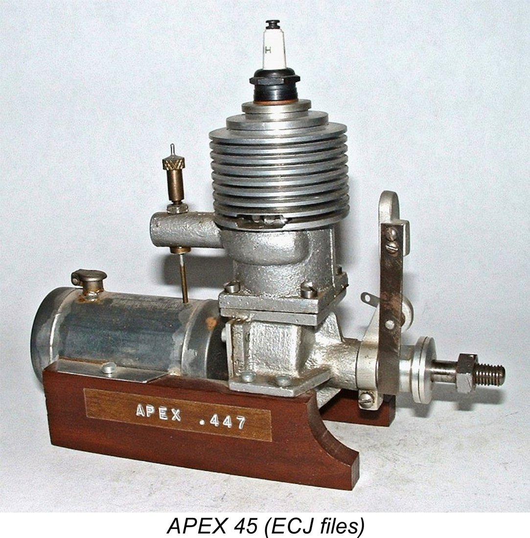
This design may very well have stalled at the prototype stage, in which case it would never have entered series production. Such a possibility is strongly supported by the fact that confirmed original examples are more or less non-existent today - the units that do turn up are invariably later reproductions based upon the materials found by Don Stroot in the residue of the APEX project which he acquired. The new design was another sideport spark ignition unit along the same general lines as the earlier APEX models. Nominal bore and stroke were 7/8 in. (22.22 mm) and ¾ in. (19.05 mm) for a nominal displacement of 0.45 cuin. (7.39 cc) exactly. My Don Sohn reproduction checks out at almost exactly these figures. It weighs in at a very reasonable 218 gm (7.67 ounces) complete with tank and plug. Don made 4 examples of this reproduction. Don Stroot also made a few examples of this model, also sharing the original castings upon which later repros have been based. Like its predecessors, the APEX 45 was built up around a sand-cast crankcase. The major change here was the adoption of a one-piece crankcase which was no longer split. As before, the well-braced but very short main bearing housing was cast in unit, with a bronze bushing being pressed in to serve as the main bearing. At the rear, the revised case was sealed with a conventional backplate retained by four screws. All in all, this was a far more “mainstream” design than its predecessors, clearly reflecting contemporary design trends as of 1936 while still harking back in some respects to the earlier APEX designs. The upper cylinder assembly continued to be a separate sand-casting with an integrally cast bypass passage and cylinder head. The bypass arrangements were unchanged apart from the fact that a single piston skirt port and matching cylinder wall opening now supplied the bypass instead of the former two holes. A significant change was the fact that the intake venturi was now cast integrally with the upper An interesting feature was the arrangement of the inlet tract. The point of entry was at the rear in the conventional location, but the mixture was then led around the cylinder's outer wall through an annular intake manifold to discharge into the case directly beneath the exhaust. The integrally-cast bulge which accommodates this manifold may be seen very clearly in the attached right-side views of the engine. An identical arrangement was later to appear on the Melcraft 29 of late 1945, although in that case a front intake was also employed. The idea may have been to promote cooling of the hotter exhaust side of the cylinder. The crankshaft was a composite component following the pattern of the crank from the 120 apart from its size. The steel crankweb was welded to the steel main journal, while the tubular steel crankpin was pressed in. The alloy cam featured on the previous APEX models was retained. The timer was a slightly modified version of the "banjo"-style component used on the earlier Skylark. A different casting was used to create the frame, but the timer was otherwise pretty much identical to that of the earlier model, complete with low-tension spring and 25 degree dwell period. If Don Stroot was correct in asserting that this model never progressed beyond the prototype stage, it's quite likely that the final production version would have featured a more up-to-date enclosed timer based on that used on the 120 model. The Skylark-style timer was probably used on the 45 prototypes for no better reason than the fact that existing components were there to be used. At the rear, the separate metal tank was identical to that used with the earlier models. It was mounted beneath the intake on the engine bearers in the same way as that of the Skylark and 120. Some examples have been seen with attached hang tanks beneath the intake, but it’s unclear if these tanks are original. The APEX Range - a Summary Having completed the above survey of the APEX engines, it remains to summarize what I believe to be the history of the range. The arguments upon which I base this summary have all been presented in detail in earlier sections of this article. I freely admit that there is no hard evidence to back up my opinions - apart from Don Stroot's stated views, all that I have to go on is a seemingly logical design progression as well as the evident Forster connection and the engines’ apparent disappearance by early 1937. I’d welcome any persuasive evidence that might either refute or correct my unsubstantiated opinions (which is all that they are). That having been said, here’s how I currently see the development of the APEX range:
Several commentators with direct experience of these engines have expressed the view that the APEX motors represented quite good value for money back in their day. The range probably died due to the manufacturer’s inability to compete with the larger-scale producers who were coming to the fore as of 1936 and beyond with more sophisticated designs. Indeed, other more lucrative fields of endeavour may have beckoned, diverting the company's attention. The fact that the APEX range never appears to have been promoted with any energy doubtless contributed to their early disappearance. Original examples are mega-rare today, although a few excellent repros like my own Don Sohn examples are still floating around. Overall, a very worthy pioneering effort by persons unknown! I only wish we knew more about the individuals involved so that their motivations could be more easily understood and their contribution openly recognized! __________________ Article © Adrian C. Duncan Coquitlam, British Columbia, Canada First published |
 In this article I’ll be presenting some information about a seemingly short-lived and extremely obscure range of model spark ignition engines from the early pioneering days of power modelling in the USA. I’ll be looking at the mid 1930’s APEX engines from Berkeley, California.
 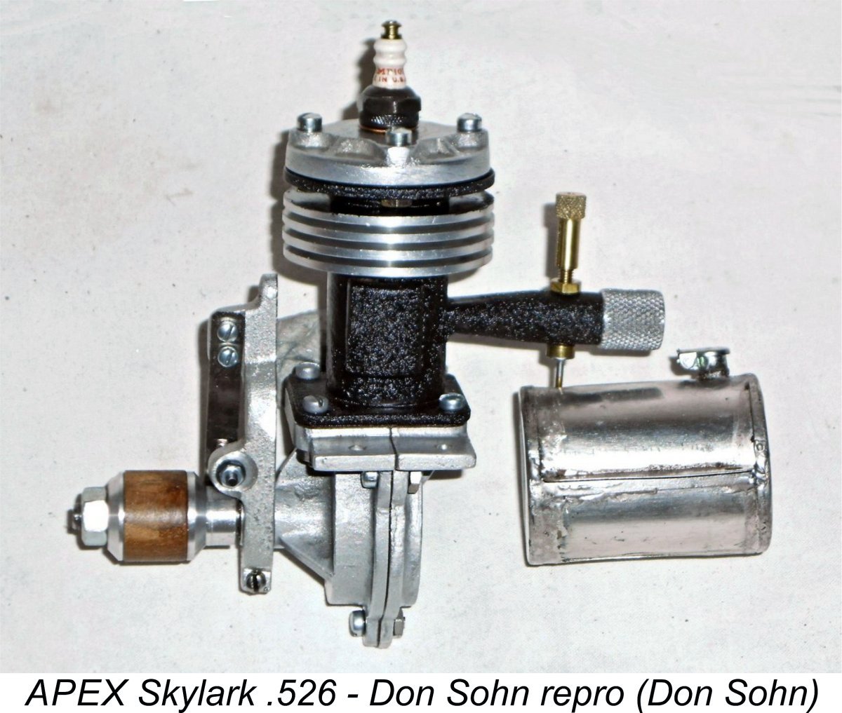 I also contacted my good friend Don Sohn, who is one of America's most respected model engine builders, to see if he had any additional information on the APEX range. I did so because Don had previously constructed a small number of faithful reproductions of the APEX models, examples of which are now in my possession. It's just as well that he did so, because original examples of these engines are rarer than rocking horse droppings - I'd never have got my hands on any examples otherwise! Many of the illustrations which accompany this article show Don’s work, which cannot be praised too highly. Don is indeed a master craftsman, without whose help I could never have written this article.
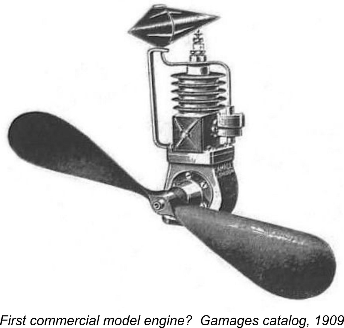
 three-cylinder four-stroke model aero engines in 1912. The Godefroy brothers soon joined in the fun, producing a very fine V-twin four-stroke model of 21 cc displacement in 1912. Unfortunately, the onset of WW1 in 1914 put a stop to these promising European developments.
 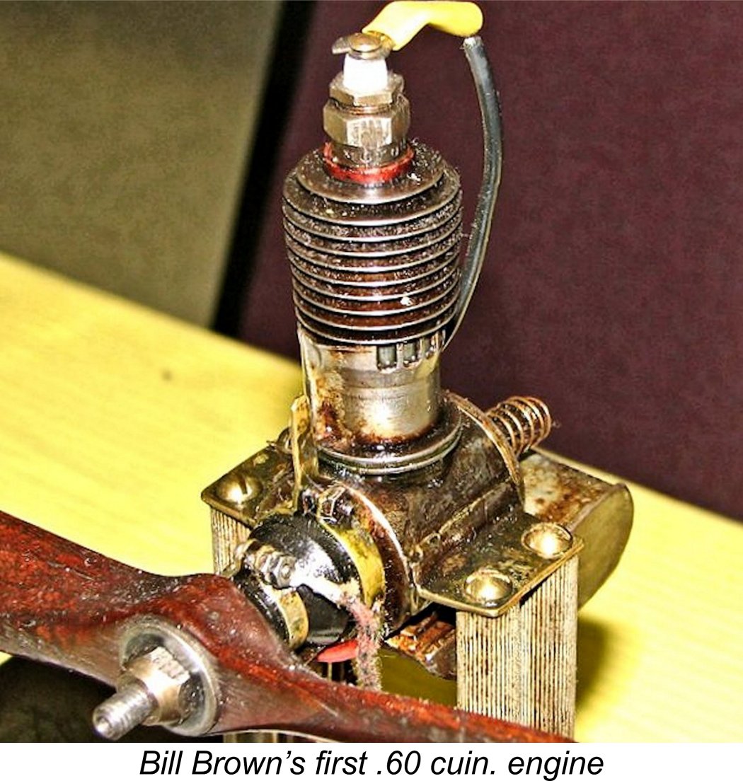 Meanwhile, in 1930 while still in high school, Philadelphian
 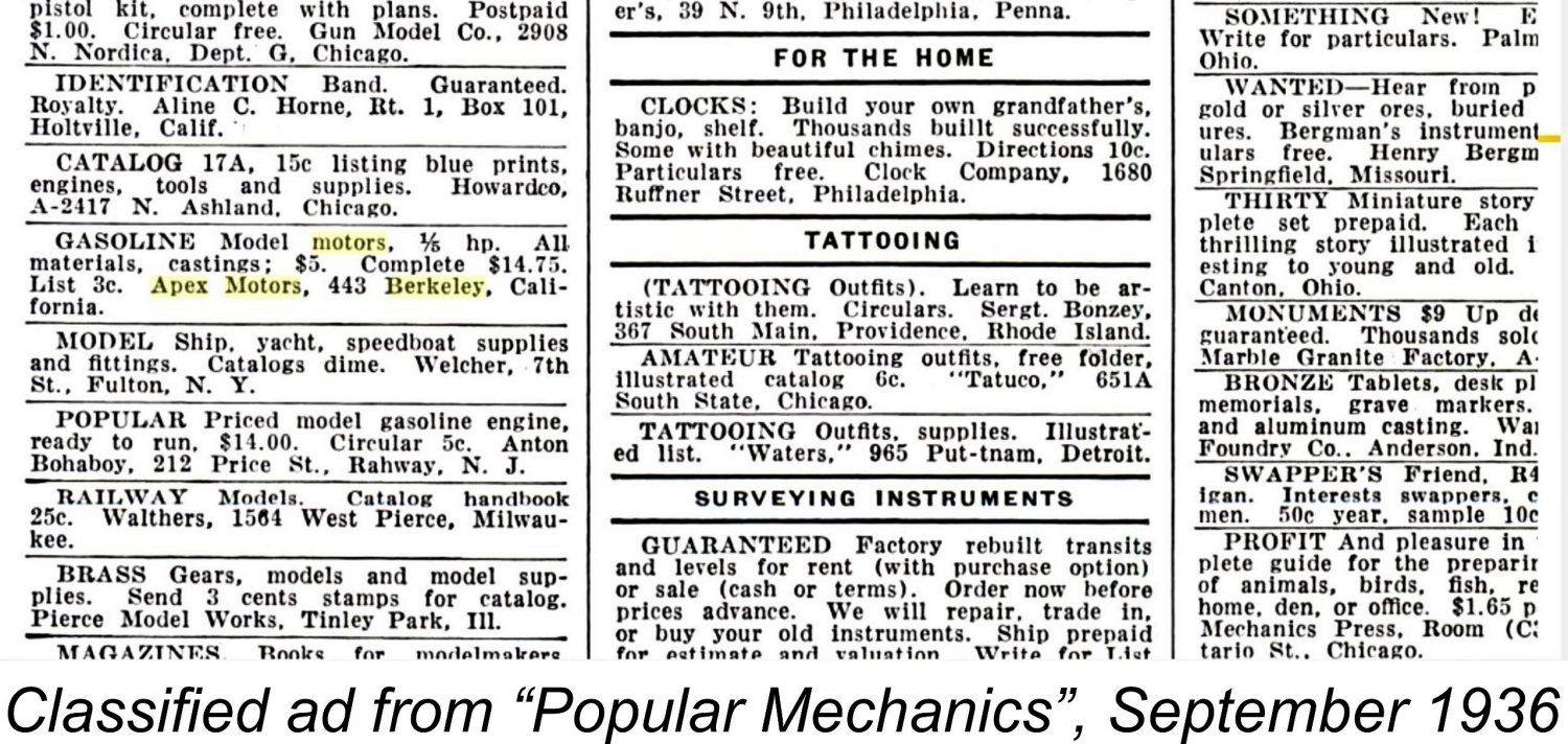 The APEX company was certainly in business as of the latter half of 1936. They placed a small and very inconspicuous advertisement in the Classified Advertisements section of the September 1936 issue of ”Popular Mechanics” magazine. Tim Dannels dug a little deeper and found similar classified ads in the September and October 1936 issues of "Model Airplane News" (MAN).
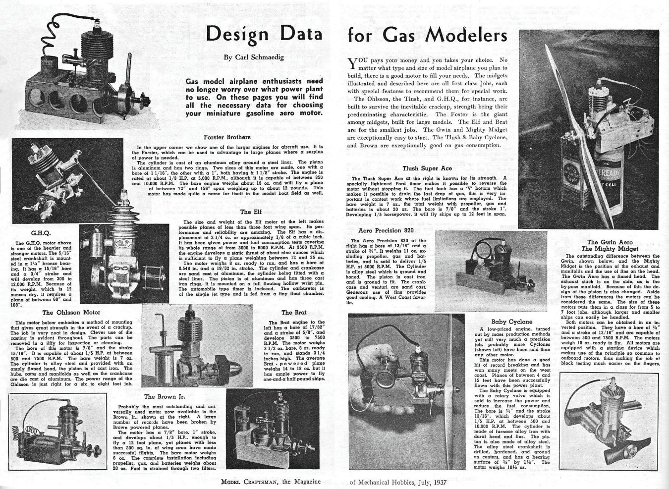
 Looking at the competition as of 1936, the relatively “primitive” structural architecture of the Skylark and Marine 53 models in particular unmistakably implies a considerably earlier introductory date for those models in particular. The suggestion in AMEE that all models appeared more or less simultaneously in 1936 does not appear to me to represent a credible scenario. We’re talking about a seemingly small company which is highly unlikely to have introduced four new models simultaneously, especially given the significant design and structural differences between them. Indeed, an objective review of the various APEX models (see below) suggests a clear design progression. Such progressions take time.
 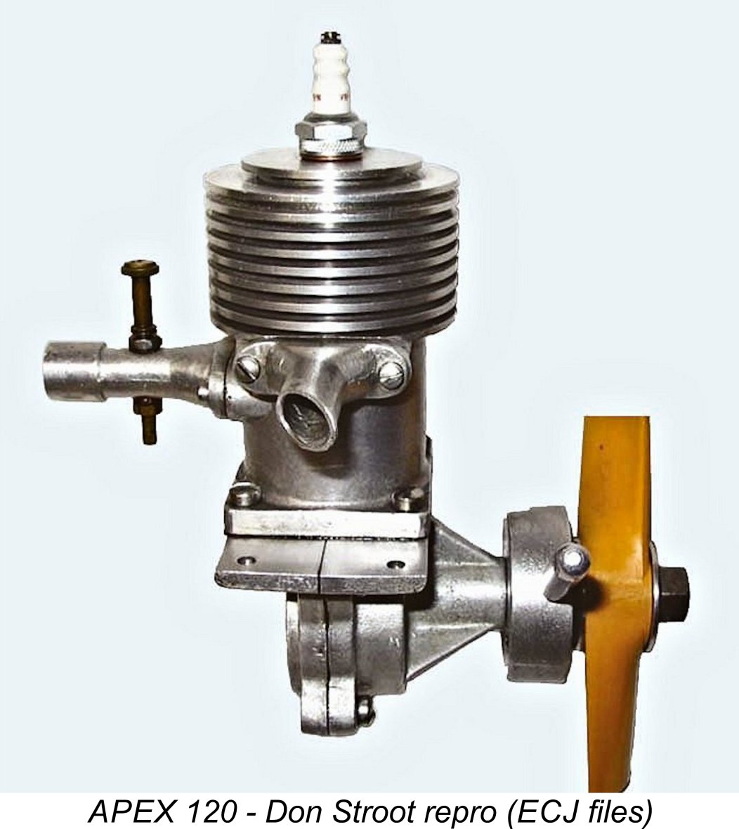 earliest designs, with the far more sophisticated APEX 120 following. The 120 retains the Skylark’s vertically-split case but adds the more elegant and more easily produced cast upper cylinder unit with inserted steel liner and bolt-on intake, eliminating the brazing operations. To me, that looks like a design advance from the Skylark - it’s very hard to envision things going the other way from the cast upper cylinder to the brazed construction.
 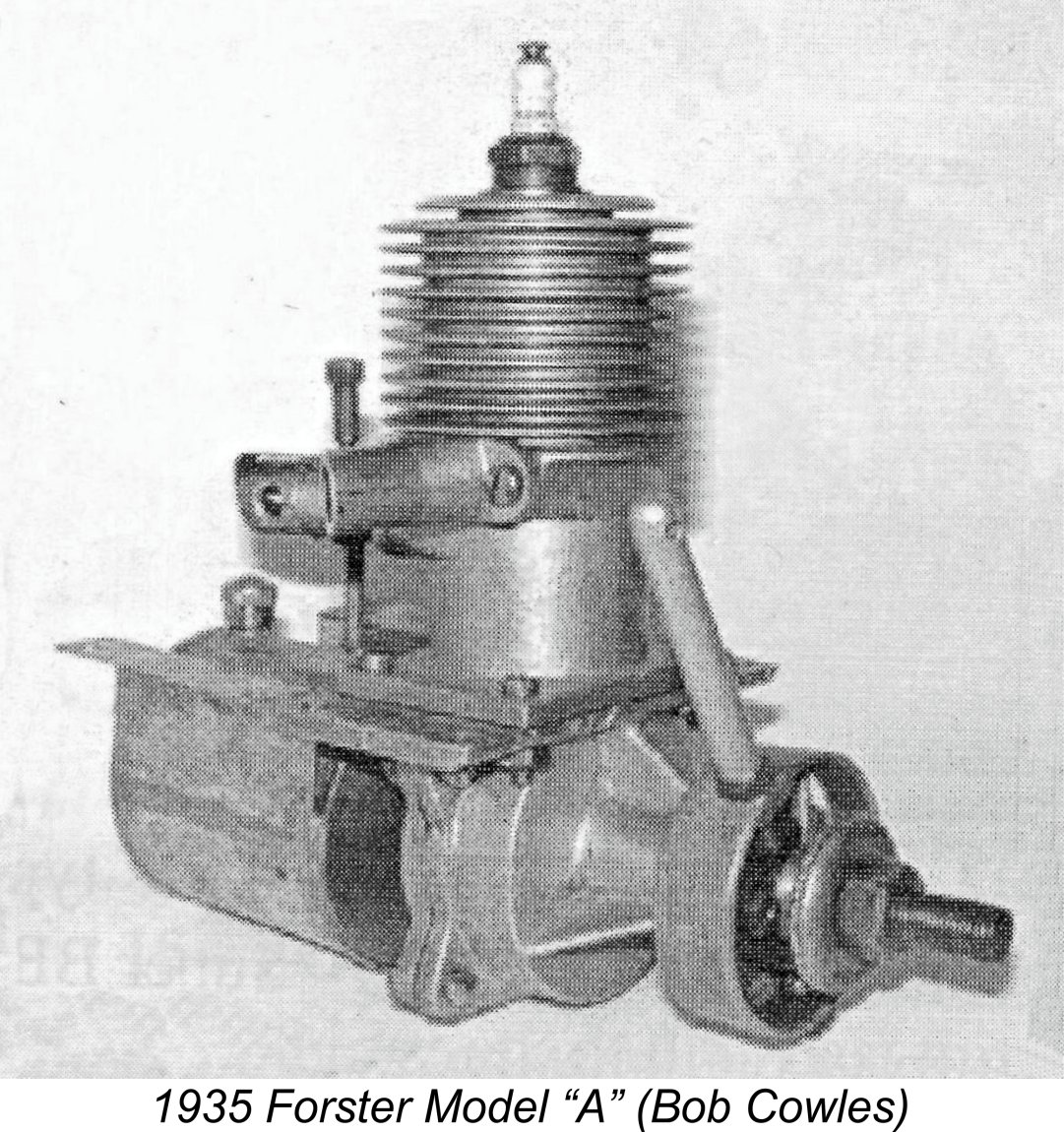 To me personally, it appears entirely possible (albeit completely unsubstantiated) that the Forster brothers looked at an APEX 120, liked what they saw but agreed that a copy having a lesser displacement (resulting in a slightly smaller and lighter engine) would be more saleable. Since they were then just cutting their teeth as engine manufacturers, copying a relatively obscure existing design would be a logical starting point. There are many other examples of this approach. The Forster brothers may well have purchased the rights to the APEX 120 as opposed to merely purloining the design.
 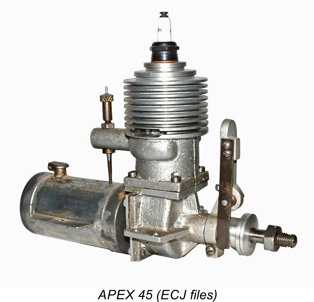 Some further support for the above scenario is to be found in the previously-mentioned technical description of the APEX 45 that was prepared by Don Stroot. The writer openly stated his view that the 45 was the final APEX model and was still under development when the company abandoned the model engine business for reasons unknown. Don's opinion was presumably based upon his considered examination of the residue of the APEX project which was then in his possession. However, he stopped short of suggesting any dates.
 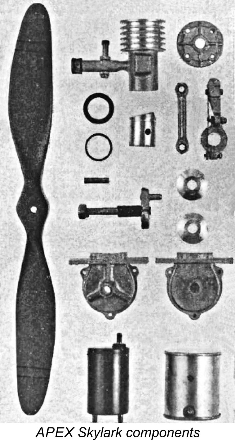 Beginning with the basics, the Skylark and Marine were both sideport spark ignition engines featuring nominal bore and stroke dimensions of
 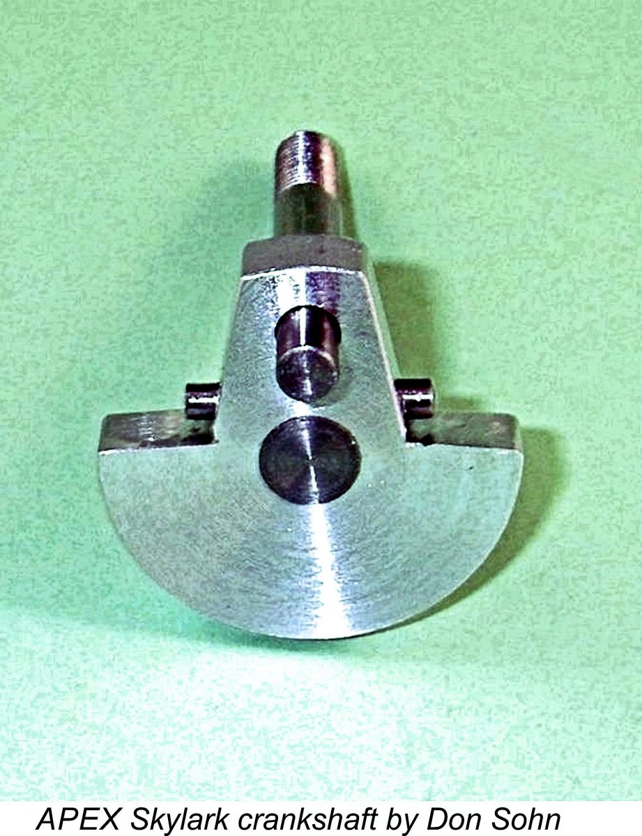 The conrod was an aluminium alloy casting with bronze bushings at both ends. Both bearings were radially drilled for lubrication. The small end engaged with a pressed-in tubular steel wrist pin, while the big end drove a crankshaft of composite construction.
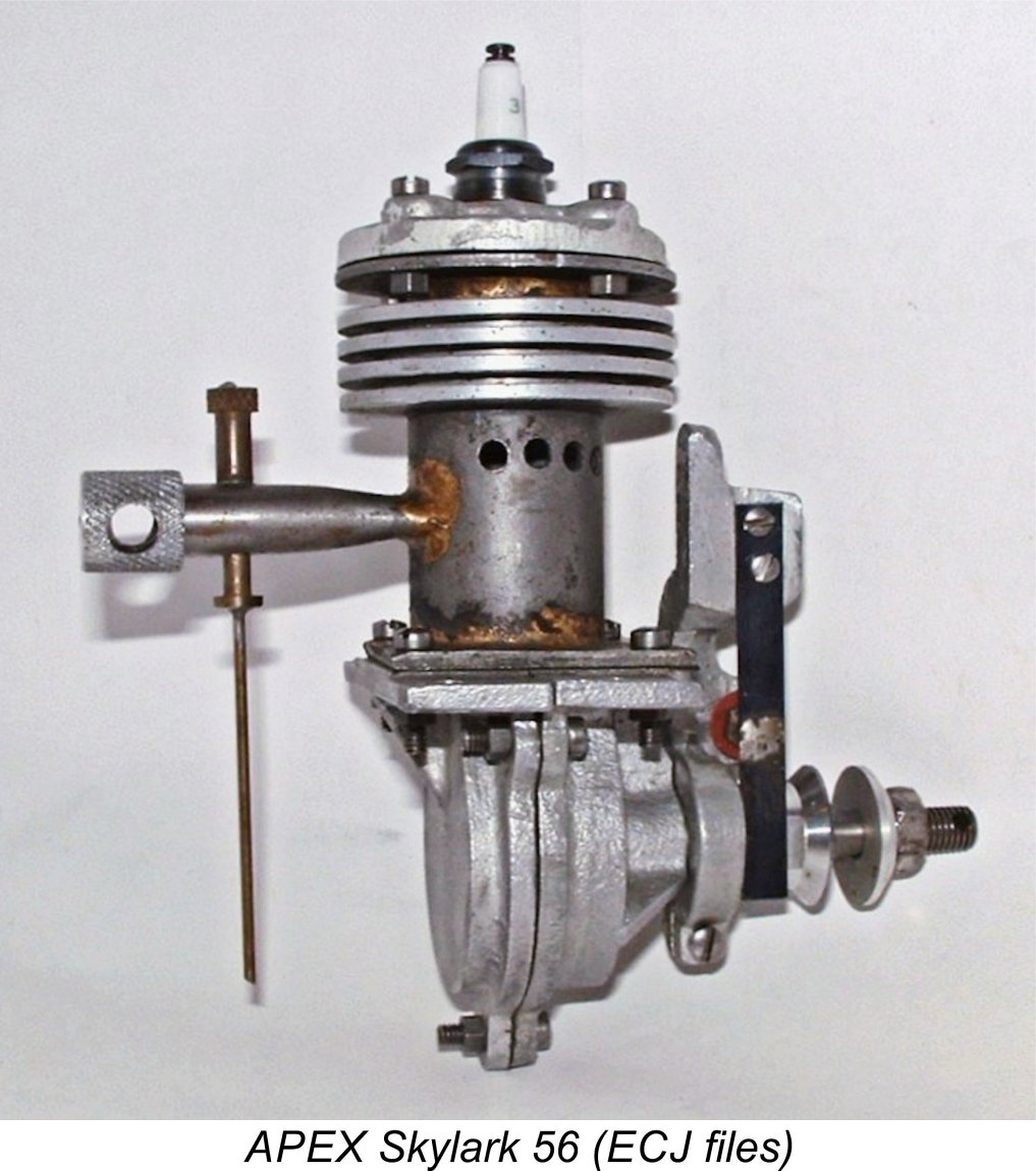
 As with any engine which was sold in kit form, individual constructors frequently incorporated their own ideas when completing the kit. Consequently, detail variations are to be expected when inspecting different examples of this engine. My own example is one of 4 outstanding reproductions made by Don Sohn. It is distinguished by the black crackle paint finish on the cylinder. Don Stroot apparently constructed a few examples in addition.
 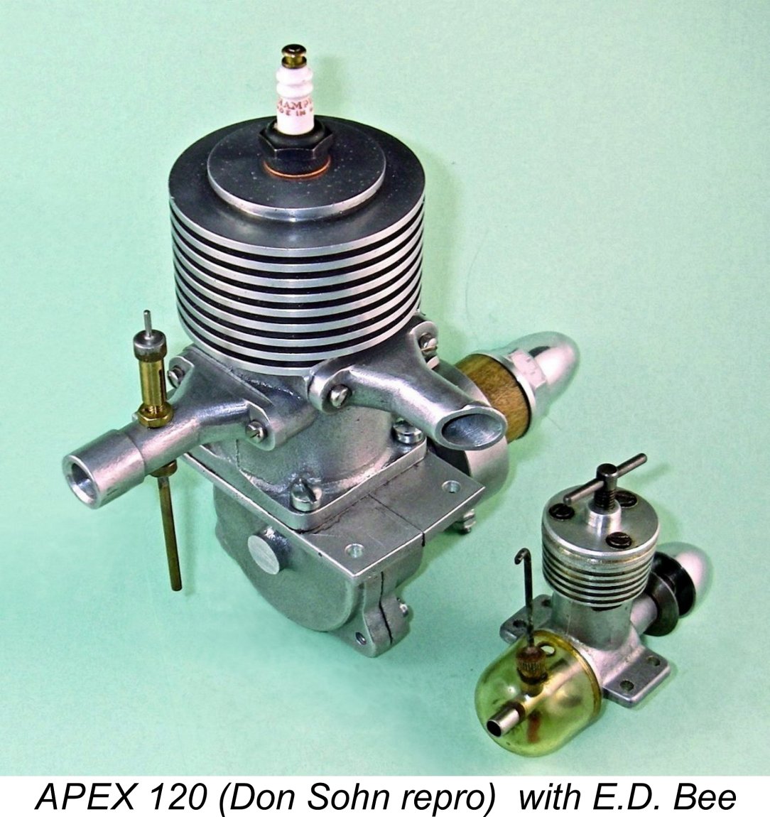 The new model was certainly quite a lump of an engine! The attached image of the 120 sitting beside an
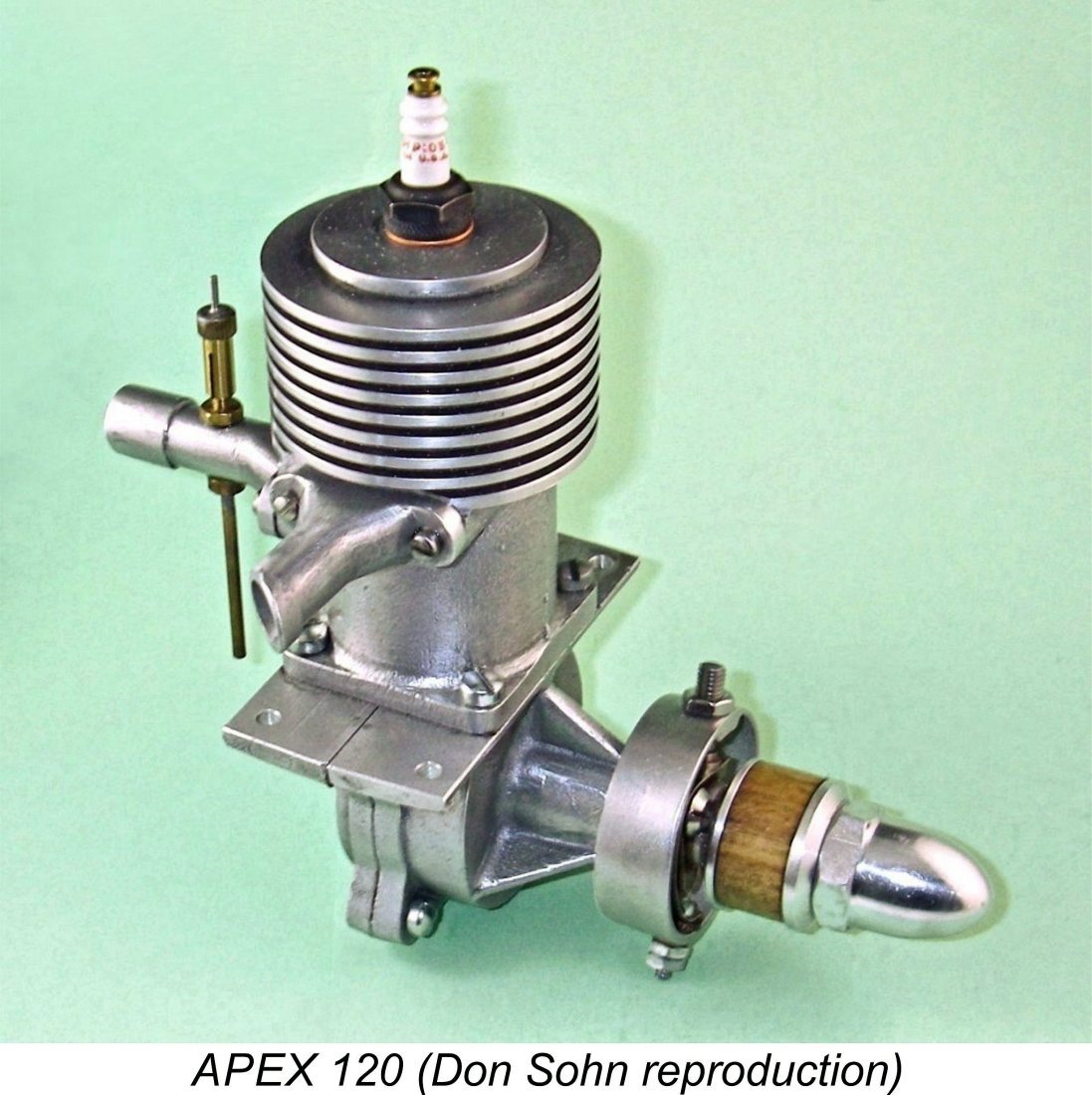
 By 1936
 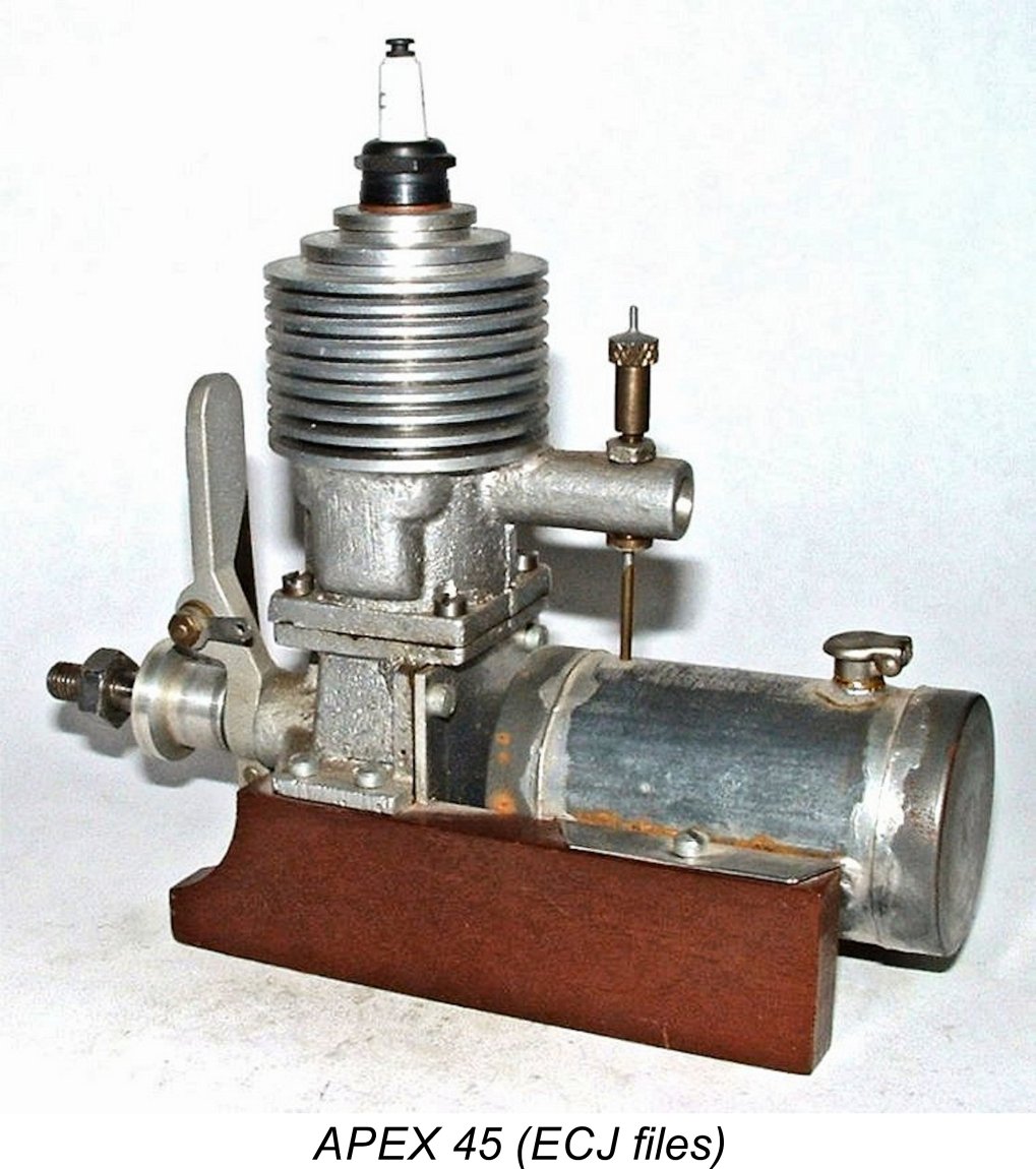 The
The 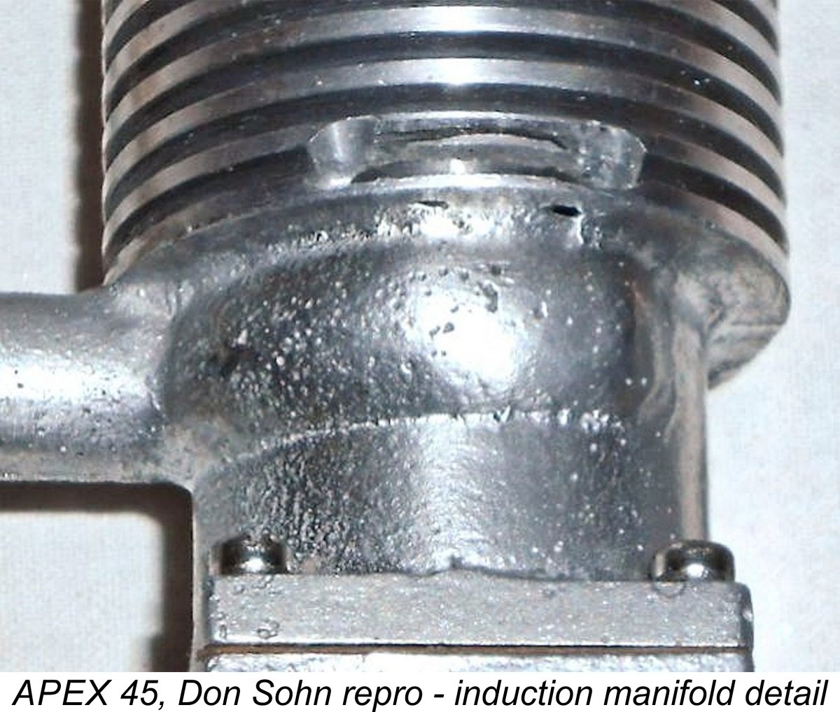 cylinder jacket. The cooling fins were machined directly into the casting. A steel cylinder liner was inserted from the base, just as had been the case with the APEX 120. A single-ringed light alloy piston was once again employed. There was no provision for an exhaust stack - a simple milled slot through the upper cylinder casting sufficed to allow exhaust gases to escape.
 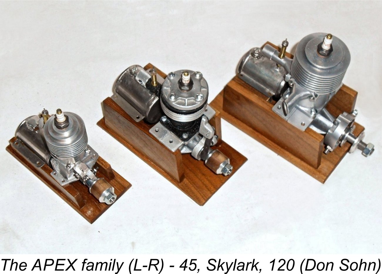 If this is how things went, then as of late 1936 the company would have had only residual stocks of the Skylark on hand. The 120 would have been sold to the Forster brothers in 1935, while full-scale series production of the 45 never really got started. This would explain completely why those late 1936 classified ads mentioned only the then woefully outdated Skylark model - production would have long since ceased and an unsold batch of those engines would have been all that remained. It all hangs together ...........
| |