
|
|
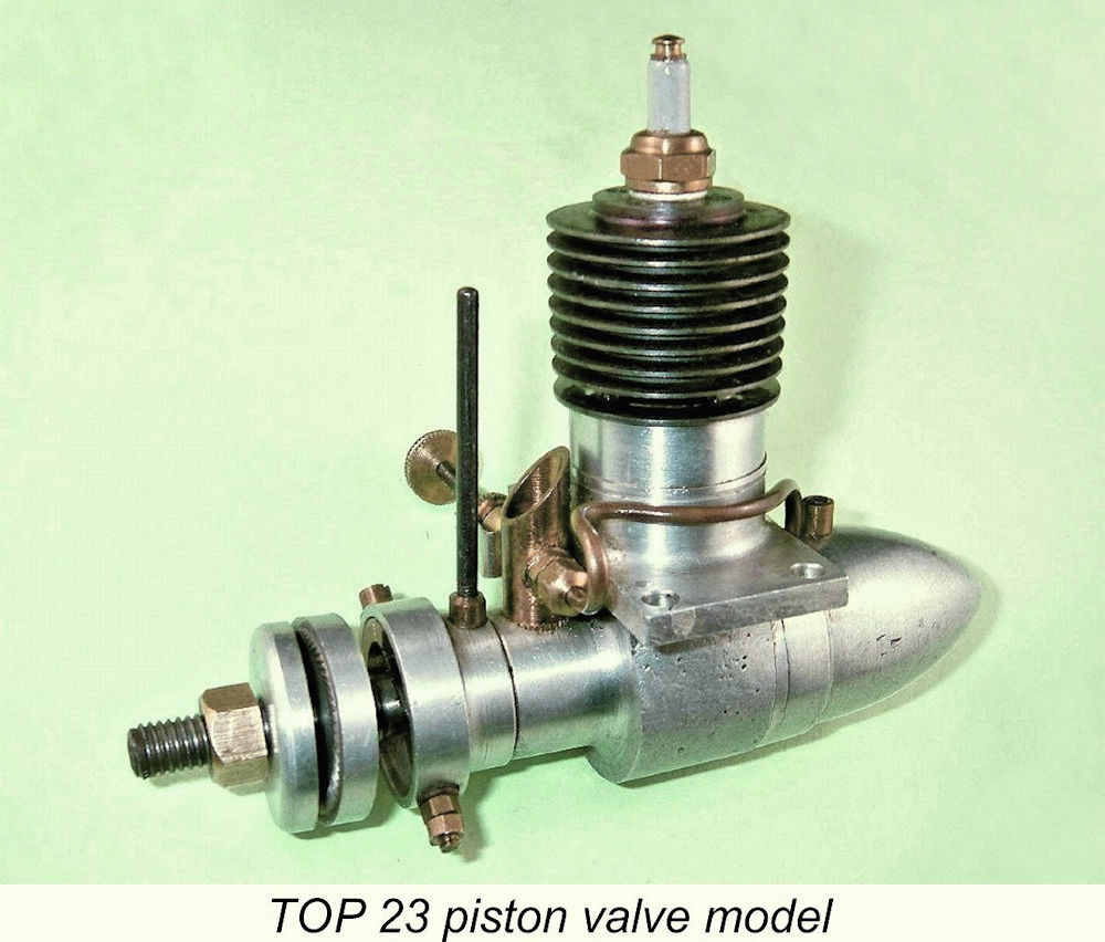
The TOP 23 Piston Valve Model on Test
In this very short article, I do not intend to repeat the bulk of the material to be found in my earlier text. Interested readers are referred to my earlier work, in which all is revealed. All that I will attempt here is to document a bench test of a representative example of one of the more interesting product lines of this manufacturer - the crankshaft front rotary valve (FRV) TOP piston valve models of 1946 in both .19 and .23 cuin. displacements. The use of a piston valve for bypass/transfer purposes is perhaps the most interesting feature of the early TOP models. Indeed, it’s an intriguing system in its own right, and one with which many present-day enthusiasts are by no means familiar. This being the case, I’ll spend a little time here describing it in some detail. The Piston Valve System Described
However, the piston valve principle had been applied to full-sized powerplants as far back as the WW1 era, when it was used in a number of rotary aero engines, albeit with limited success. It’s possible that the TOP designer had somehow become aware of the cited American models or had acquired some knowledge of the WW1 experiments - after all, Japan was an Allied nation in that conflict. Alternatively, this may be a case of independent parallel development - we’ll probably never know. In the piston valve system, the conrod and gudgeon (wrist) pin are carried in a shuttle piston of smaller diameter than the main bore. The main working piston is nothing more than a thin unbroken shell which is finely finished and closely fitted both inside and out. The shuttle piston is accurately fitted to the secondary bore formed within the working piston shell, being free to slide up and down within the working piston. The shuttle piston is retained in the working piston using an internal circlip around the base of the working piston shell. This circlip sets the limit on the axial movement of the shuttle piston relative to the working piston.
The seal is maintained until the exhaust ports open and the gas pressure above the piston is relieved. Even then, the momentum of the now rapidly decelerating piston assembly as the crankpin swings towards the bottom of the stroke would keep the valve closed were it not for the fact that an internal ledge (often cushioned by a fibre washer) is provided at the top of the crankcase casting to limit the downward movement of the working piston. When its lower skirt meets this ledge, the already-decelerating working piston necessarily stops descending. This accounts in part When the working piston stops descending, the internal shuttle piston continues to follow the conrod by descending inside the working piston, thus opening the central hole in the working piston crown. Circumferential venting in the crown of the shuttle piston allows fresh mixture to pass freely through the interior of the shuttle piston around the conical seating area and thence through the central hole in the crown of the working piston into the cylinder. Neat, eh?!?
Complicated though it may sound, this system works surprisingly well despite being mechanically ill-adapted to high speed running as well as creating a somewhat constricted transfer gas pathway along with a limited transfer period. The working piston is free to rotate within the bore, a factor which combines with the impact of repeated valve closures to maintain a good mating fit between the sealing surfaces of the shuttle and working pistons. In addition, the repeated passage of gas through the valve minimizes the build-up of foreign material in the seating area as well as keeping the shuttle piston and upper rod bearing well cooled and lubricated. Finally, the presence of oil in the mixture both protects the valve surfaces against undue wear and improves their sealing qualities. Naturally, I was curious to see for myself just how well the system worked in real life. Only one way to satisfy my curiosity - head for the test bench! The TOP 23 Piston Valve Model on Test
Bore and stroke measurements of the tested unit are a nominal 15.4 mm and 17.4 mm respectively, the resultant displacement being 3.66 cc (0.223 cu. in.). The checked weight with tank and plug is a not-unreasonable 176 gm (6.21 ounces). The engine appears to be very well made, as indeed it has to be for this mechanically-intricate operating system to work effectively. Since I described the TOP 23 in some detail in my earlier article on the TOP range in general, I won’t repeat that description here beyond commenting that the timer is a rather rudimentary design which lacks a moving point. The flat leaf spring which closes the It seemed to me that this timer might possibly represent a limiting factor on this engine’s performance. I therefore paid particular attention to the routine timer function test which I always perform before running a sparker. Happily, the test was completely satisfactory in this instance. Since the original TOP spark plug with which the engine was fitted was also in excellent working condition, I used that plug for the test. Set up in the test stand with an 11x7 Zinger wood prop fitted, the TOP undeniably felt a bit "odd" when flicked over, while the clicking sound of the valve in operation was very detectable. There was clearly some leak-down through the piston valve at flicking speed, but that is to be expected with this system - it takes the elevated sealing pressures created by the engine actually running to achieve a really secure seal. Even so, the engine undoubtedly had more than ample compression for starting when flicked over.
Things got off to a very encouraging start - the engine commenced firing immediately and was running a few flicks later. I’d guessed a little rich on the mixture, but a tweak of the needle and some advance of the ignition timing soon had the engine turning the 11x7 prop at a smooth 4,500 rpm on a slightly rich and retarded setting. I was quite impressed at how smoothly the engine actually ran - although there was a little audible valve clatter, it was far less than I had been expecting.
One positive factor that asserted itself during this initial running was a very definite improvement in the seal provided by the piston valve during starting. After a few runs, the engine now held its compression seal very well when turned over - almost like a normal lapped-piston model, in fact. It appears that the repeated opening and closing of the valve under pressure was having the effect of lapping the sealing faces of the shuttle and working pistons. One could certainly feel the very low compression ratio of around 5.5 to 1, but it was clearly adequate for operation on spark ignition. Since I didn’t want to put too much running time on this pristine example of the engine, I limited subsequent runs to the duration necessary to establish the best stable operating settings for each prop tested. As it happened, it only took a further 3 props to define the engine’s peak. The data obtained were as follows:
The implied output is of the order of 0.100 BHP @ 6,000 rpm. This is actually a perfectly respectable performance for a 3.66 cc sparkie by 1946 standards, beating both the contemporary British Mechanair 5.9 cc and Atlas 3 cc models by some margin, for example. Overall, I’d have to say that I was far more impressed with this engine than I had expected to be at the outset. Apart from its excellent handling and running qualities, it seems to be well able to maintain its performance over the long haul. No mechanical issues of any kind presented themselves during this test, and the timer clearly worked very well indeed up to the maximum speeds tested - no ignition difficulties presented themselves at any time. So hats off to the unknown TOP designer! He seems to have created an engine of considerable utility here! I’ve also acquired a healthy respect for the effectiveness of the piston valve principle within its inherent operating limitations. If you're ever lucky enough to get the chance, have some fun giving one a try - you might be as surprised as I was! ______________________ Article © Adrian C. Duncan, Coquitlam, British Columbia, Canada First published August 2023
|
||
 Elsewhere I’ve written about the rather obscure
  In a model engine context, the piston valve system dates back to 1939 America, when the


 As the rod and attached shuttle piston pass through bottom dead centre and begin to move upwards on the compression stroke, the shuttle moves up within the working piston to first close the piston valve, thus contributing to the "clattery" sound, and then to cause the working piston to rise again with the valve now closed and ready to resist compression and combustion pressures. Thus the cycle is repeated.
 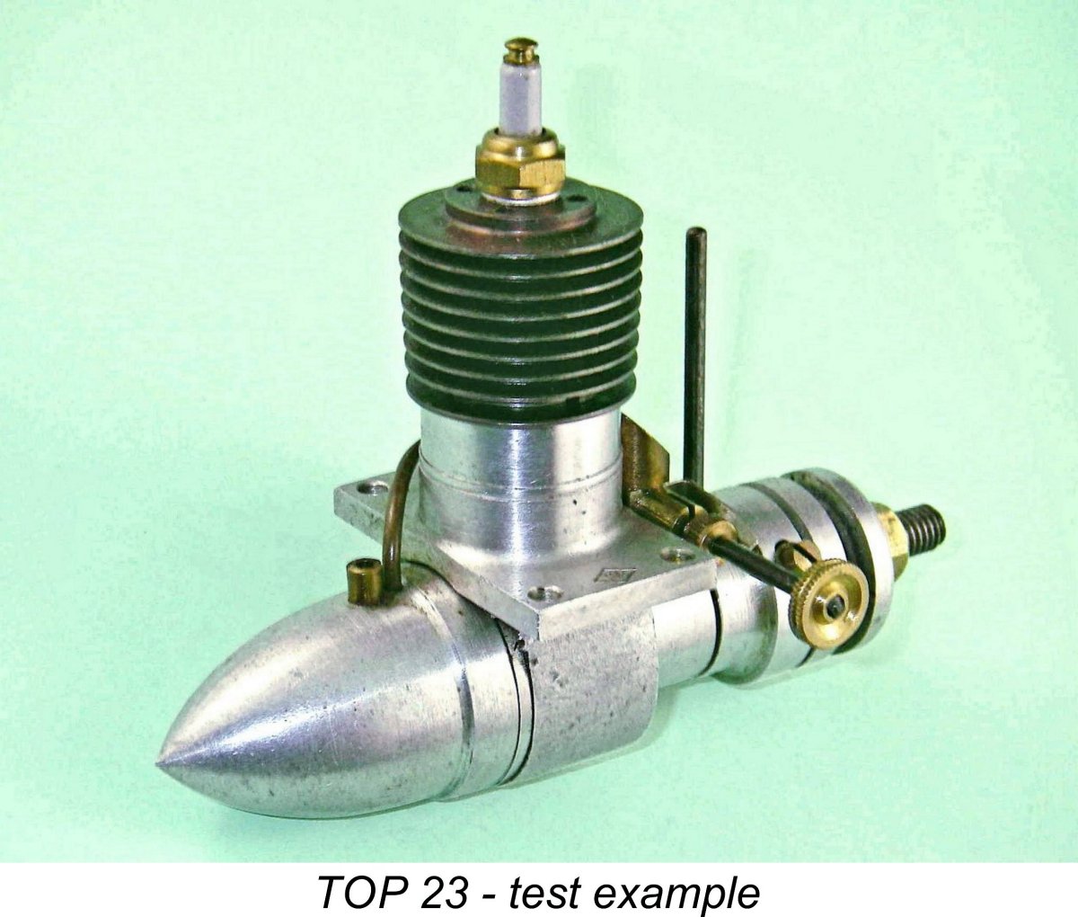 For this test, I used my near-mint example of the TOP 23 FRV spark ignition piston valve model from 1946/47. I’d had this engine for some years but had never got around to running it. In fact, this was the first occasion on which I’d actually tried running a piston valve engine of any make. Needless to say, I was very curious to see how this rather unusual design arrangement would work in practise!
 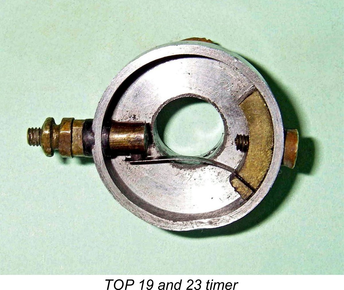 primary circuit does double duty, serving as both the cam follower and the moving point. Provision is made for precise adjustment of the gap. Hopefully the accompanying image will make this arrangement clear. The dwell period is relatively short - around 40 degrees - indicating a design expectation that the engine would not be operated at high speeds.
 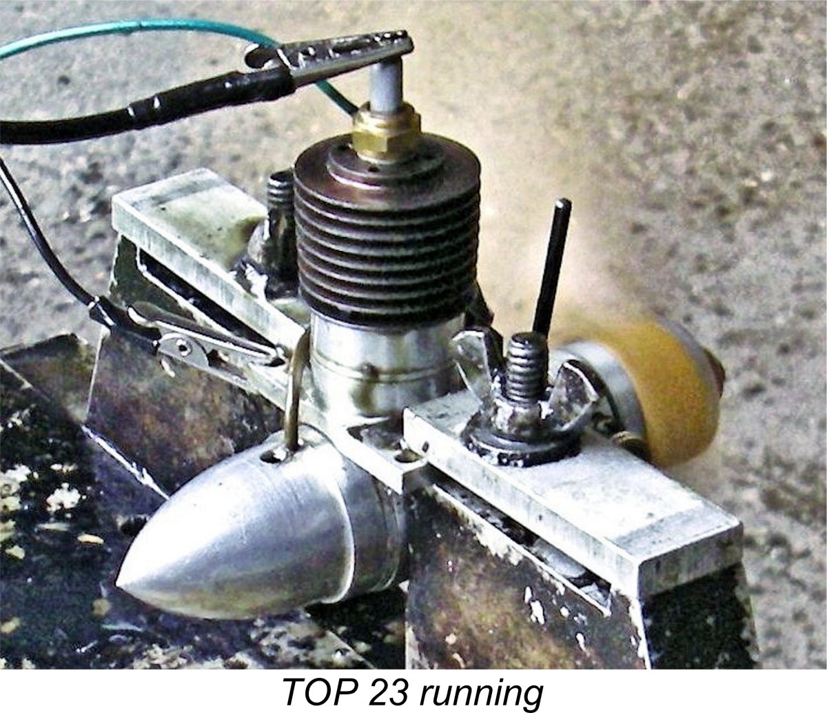 I set the needle by guesswork at 2 turns, set the timer in the starting position determined during the earlier timer check, hooked up the ever-dependable
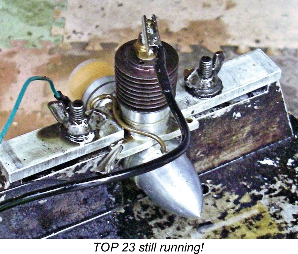

| |