
|
|
Model Engine Plans for Home Construction
This new page will confine itself to plans for engines not captured in any of the above pages. For convenience in locating a particular plan, the entries will appear here in alphabetical order rather than in the order in which they were received. Any reader having access to hi-res (i.e., legible and basically unmarked) plans not included either here or elsewhere on this website is hereby cordially invited to submit them to me for publication along with a clear and representative photograph of a complete example of the engine in question and any construction guidance which may be available. As always, I reserve the right to confirm the suitability for publication of any material submitted and to write my own commentary on the engines represented by the plans. I also remain open to the submission of additional articles on various aspects of the home construction of model engines in general. If accepted for publication, any such submissions will be added to the Technical Topics pages on this website. Once again, I reserve the right to edit any such submissions. The following is an alphabetical listing of the plans which presently appear here. More will be added as additional plans are received. Clanford Clan 0.24 cc diesel DragonFlea diesel - either 0.113 cc or 0.154 cc displacement Holly Buddy 2.5 cc diesel Nalon Viper 2.5 cc diesel Rogstadius 2 cc diesel (Swedish Dyno copy) Sugden Special 2.5 cc diesel VIKHR 2.47 cc diesel Wilsco 79 0.79 cc diesel TOP 20 sparkie Details of each of these engines follow below. Clanford Clan The well-known little 0.24 cc Clanford Clan sideport diesel has been covered in some detail by Maris Dislers in a separate article to be found on this website. Because it uses no castings, this engine makes an attractive home construction project, especially for those who have only small machine tools. The plans for the Clan are included in the “Members Only” plan book developed by Motor Boys International and subsequently organized and shared by Ken Croft. That publication may be found elsewhere on this website, including the plan for the Clan.
I’m therefore most grateful to Ken Croft for setting down his own approach to the construction of one of these neat little diesels. Moreover, at my request Dave Jones was very happy to add his own comments to what Ken has written. There’s no incompatibility here because Ken and Dave corresponded with each other regularly during the course of Ken’s construction efforts. The two constructors agreed to differ on a number of relatively fine details, but both achieved splendid results. So what follows represents an invaluable experience-based guide to the construction of the Clanford Clan by two of the finest model engineers with whom it has been my pleasure to correspond. I’ll present Ken’s notes more or less as received, with comments from Dave inserted in italics as appropriate. As I've said, the two didn’t agree on all points, but results speak for themselves and both guys have produced superb examples of the engine, albeit with a few minor differences. Decide for yourselves! Either way, I’m sure that anyone tackling one of these engines will find these comments to be extremely helpful. Ken Croft writes: I have recently built a Clanford “Clan”, working to the plans in my “Members Only” plan book. It starts easily and turns a KeilKraft 5x3 prop at 10,000 rpm. Videos of the engine running can be seen here and here. The first of these videos documents the initial problems which are always encountered when establishing the settings for the first time. The second video shows the engine after a few runs with settings established.
Dave Jones agrees - he comments that although pressed in crank-pins (as per the drawing) may appear to make manufacture easier, he agrees with Ken that they can be very difficult to get right, especially in smaller engines. Dave used one-piece crankshafts machined from high-tensile steel in his initial batch of five engines. He also deviated from the drawing in that the threaded propeller shaft in his engines is a separate 6 BA mild steel stud, which makes a good crankshaft saver.
Dave Jones comments that if one is following the Motor Boys drawings, the conrod to cylinder/crankcase clearance issues are quite well documented on various internet forums. Dave’s solution was to reduce the conrod shank diameter in one direction from 3 mm to 2.8 mm (about a 7% reduction). He ended up with a conrod shank of 2 mm x 2.8 as opposed to 2 mm x 3 mm. If it’s made from a suitable aluminium alloy (7075-T6), the rod is still quite substantial and well up to the task. Ken and Dave discussed this and Ken felt that the rod should be left as drawn. Dave’s view is that the drawings show no clearance cut into the crankcase and that the rod was possibly measured/drawn slightly incorrectly.
Dave Jones comments that he made the gudgeon pin a press fit into the piston. He admits that this is probably just him, but he hates the thought of the pin end rubbing on the cylinder wall, no matter how lightly, even if there is no port for it to snag. He also reams the piston bosses for longevity.
At the time of writing, Dave Jones was keeping an open mind on whether or not the 9 BA called for on the head bolts was in fact a mistake. A collector was sending Dave an original Clan to be made right (manufactured timing issue) so he was expecting to be able to determine at first hand exactly what thread was used for the original head bolts. Dave notes that the remainder of the engine threads as drawn are BA or imperial TPI. Since he didn’t have any 9 BA tooling at the time, he went with Ken’s suggested M2 for his initial batch, since the size and TPI of both are pretty close, with really just a slightly different thread form. He thinks that 8 BA may be a little large for these bolts. His next batch of Clans may well have 9 BA head bolts, since he has now found a source of reasonably priced 9 BA taps and steel cheese-head machine screws.
Dave Jones confirms that the tanks supplied with his engines are the centrifuge test vial bottoms. The downside is that they are quite a bit larger that the original tanks if anyone cares. The tank tops/venturi fitted to his engines are machined in one piece from aluminium rather than being composite items or being made from molded plastic as per the originals. This of course is a builder’s choice.
Dave Jones comments that of the 5 engines he has built so far, two had leaks from a least one of the head bolt to case holes. Subsequently, all 5 engines had the threads sealed with balsa cement (a tip from Maris Dislers on this website). None of them leaked from the cylinder base, which may be because the sealing edge of the cylinder is chamfered as per the drawing. Dave also added a paper backplate gasket to each engine as one of them leaked in this area.
In Dave Jones’ view, initial piston fits cannot be too tight as the Clan is a very small engine with small components. Dave’s own Clan (no. 01) didn't come close to Ken's rpm figures until it had about 30 minutes total running time. Dave makes the general comment that there is often more than one way to skin a cat and Ken built his lovely Clan as an occasional runner whereas Dave’s examples are intended to be used. Either way, the Clan is a fairly straight-forward build. The difficulties faced by the builder are mainly due to the fact that the engine is quite small. This means that tighter tolerances are required than for a more “normal” sized engine. Well, there you go! I hope that this inspires a few more people to have a go at building their own Clanford Clan! ______________________________ DragonFlea
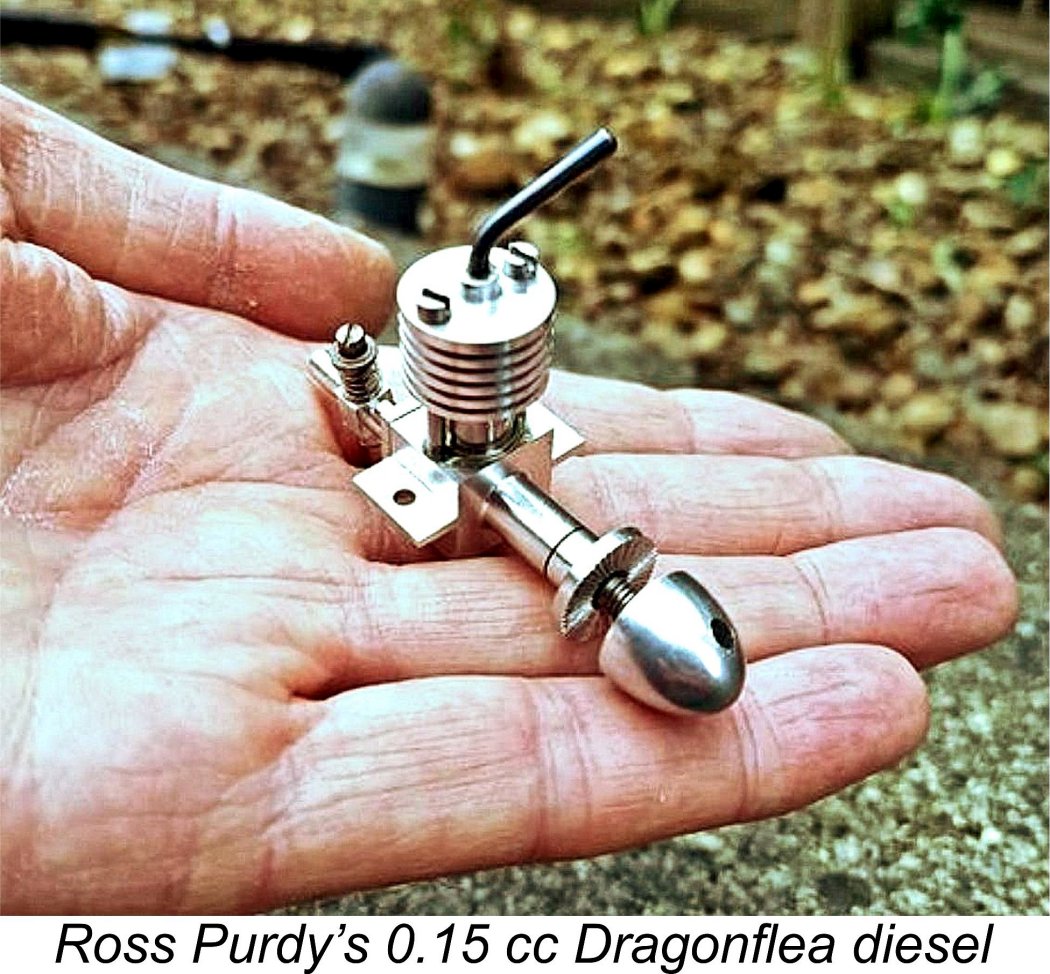
The Dragonfly was individually hand-made by its unknown constructor. No castings were used in its construction. Surviving examples are a bit like hen’s teeth, but they do exist - Mike Clanford illustrated several examples in his “A-Z” book, as did Ted Sladden. The engine was also pictured in several contemporary modelling periodicals. Thankfully for posterity, the well-known model engine constructor and restorer Mike Crompton had one of the very rare original examples through his hands for repair some years ago now. He made a few very rough sketches with some key dimensions, from which the late and much-missed Ron Chernich was able to cobble together a set of CAD drawings for the construction of a credible near-replica. Because he couldn’t guarantee that his drawings accurately reflected all aspects of the original engines’ construction, Ron called his rendition the “DragonFlea”! These plans were long thought to have been lost, but amazingly enough I recently (2020) stumbled upon a set which Ron had sent to me several years prior to his untimely demise in early 2014. I had completely forgotten that I had them! However, now I can make them available to all through this link. Ron’s drawings provide details for making two versions of the engine. Both have a stroke of 0.250 in. (6.35 mm), but the smaller version has a bore of 0.1875 in. (4.76 mm) for a displacement of 0.113 cc while the larger version uses a bore of 0.2187 in. (5.55 mm) for a displacement of 0.154 cc. Take your pick…………… and good luck! Those of you wishing to have a go at one of these units are greatly indebted to the mega-talented model engine builder Ross Purdy of New Zealand for not only taking the plunge himself but for sharing his impressions and experiences with us. As stated above, the drawings show two different engine sizes - 0.1 cc and 0.15 cc. At the start Ross decided to make the 0.15 cc engine, thinking it would be easier to get a bigger engine to run. After struggling to complete his 0.15 cc example, Ross states that if he were to do this again he would definitely tackle the 0.1 cc version. It seems that the carburettor dimensions are set for the smaller version. A 50% larger displacement requires appropriate changes to the carburettor design (jet & inlet size). In addition, the cylinder wall thickness is compromised using the larger bore. Ross lists the changes that he recommends to get one of these engines running as follows.
After all this effort, Ross ended up with a nice-looking example of this engine that runs fine. He hopes that his experiences will help other who wish to have a go at making one of these fascinating miniatures. A video of Ross’s engine running on a 5.5x4.5 prop for extra flywheel effect may be viewed here. Holly Buddy The Holly Buddy is a really nice-looking radially-mounted 2.5 This engine was designed by Ed Holly, who published a photographic essay on its construction on the Home Model Engine Machinist website. That essay remains available online through the link provided. Here I'm making Ed's own pdf commentary available along with the plans for the engine. Hopefully a few of you will have a go at building your own examples! Click here to bring up Ed's commentary along with the plans for the engine. Designer Ed Holly was kind enough to send an example of this engine to my good mate Maris Dislers. A detailed review and test of the engine appeared in issue no. 980 (January 2019) of "AeroModeller" magazine. Maris found that while the Buddy is no powerhouse by present-day standards, its general handling and running qualities were very good indeed. In his view it compared quite favorably with such well-regarded 2.5 cc sport diesels of the early 1950's as the FROG 250 and the David-Andersen "twin stack" 2.46 cc model. As such, it appears to be a very suitable powerplant for use in a re-creation of a retro-classic model. ______________________________ Nalon Viper
The designer's stated intention was to make an engine available that would offer a competitive alternative to the then all-conquering Oliver Tiger Mk. III in the very popular Class A team race event. Peter Chinn's preliminary testing of the prototypes confirmed that the engine would very likely have achieved this goal in performance terms. Each engine was virtually individually hand-made, the standard of construction accordingly being very high. The intent was apparently to make around 100 examples of the Viper, which were to sell for the premium price of £9 - a small fortune in mid 1950's Britain. However, in the event this goal was never achieved - few if any examples of the engine ever reached the hands of practical aeromodellers of the day. Because of its bar-stock design, the Viper is a very suitable candidate for home construction. A plan was produced by the Motor Boys International group, and a number of examples of the engine have been successfully built from these plans, among the builders being Charlie Stone, whose example appears here. Another notable maker was Motor Boy Eric Offen, whose superb reproductions are stamped EJO on the borttom of one mounting lug, thus preventing their being passed off as originals. For the full Viper story, see Ron Chernich's Nalon Viper article which may be found on Ron's "Model Engine News" (MEN) web-site. The Motor Boys plans for the engine may be accessed through this link. _______________________________ Rogstadius 2 cc Diesel Plans Actually, this is not a completely new addition to the range of available plans - rather, it is a supplement to a previously-published set of plans. Most readers will be familiar with the well-known Swiss Dyno 2 cc sideport diesel of 1941. Although it wasn't the first commercial diesel (that honour belongs to the 1938 ETHA series, also from Switzerland), this iconic design was indisputably the first commercial model diesel to achieve widespread popularity. Ron Chernich's plans for the engine are already available as an inclusion in the "Motor Boys Plan Book" which is already published on this site.
The intent all along was to publish the drawings in "Teknik för Alla". Ivan later recalled that he completed the drawings in the winter of 1942/43 without changing any aspects of the original Dyno design. He then built his first engine for the purpose of evaluating its usefulness. Following bench testing, a free flight model fitted with this engine was successfully test-flown at Skarpnäck, a small airfield south of Stockholm. A report of this test flight was published in the magazine "Svensk Flygtidning", issue number 7, July 1943. Ivan's plans were finally published in "Teknik för Alla's" December 1943 and January 1944 issues, together with his construction notes. In effect, they allowed the builder to construct his own Dyno clone. An amazing number of individuals appear to have done just that, particularly in the Scandinavian countries where Ivan's article received wide circulation. As a result, many Dyno's encountered today aren't Dyno's at all - they're replicas or near-replicas constructed by others. Buyer beware!! Of course, there's nothing wrong with this provided the replicas are clearly identified as such. To make both Ron's plans of the original and Ivan's plans for the replica available, Ken Croft has been kind enough to reproduce Ivan's plans in TurboCAD form along with Lars Gustafsson's illustrated translation of Ivan's Swedish-language construction article. This material may be accessed here, with our very sincere thanks to Ken Croft. Ken notes that there are a few differences between the two sets of plans - you choose!! The full Ivan Rogstadius story may be read here on Ron Chernich's "Model Engine News" (MEN) website. __________________________ Sugden Special Next up is a classic from 1950's England - the famous 2.5 cc Sugden Special. Designed by professional dentist and skilled machinist Dave Sugden (who subsequently became a fellow resident of Canada), this engine formed the central subject of a series of construction articles by Dave Sugden which appeared both in the pages of "Aeromodeller" magazine (beginning in December 1954) and later as several chapters in the 1958 "Model Aero Engine Encyclopedia" from the same publisher. The plans for the engine were also published at the same time, with arrangements also being put in place to make sand-cast crankcases available for the use of home constructors. Subsequently, my late and much-missed mate Ron Chernich wrote a most informative article on the More recently, I've had a few inquiries from various readers regarding a source of the plans and castings for this very well-designed and strong-running powerplant. Thanks to the kindness of Ken Croft in supplying a hi-res scan of the plan, I'm now able to make it available here. I've also created a pdf file containing the original construction article for the engine. The construction of this engine requires the builder to somehow obtain an example of the main crankcase casting. Currently I have no information regarding where or even if these castings may be obtained. There is a possibility (and it is no more than that) that my fellow Canadian and former casting supplier Andrew Coholic may be inspired to produce a further batch if there is sufficient interest. The illustrated example of the engine was constructed by Andrew from one of his own castings and was very kindly presented to me. I plan to publish a test in due course. Meanwhile, Andrew's video of this example running may be viewed here. _______________________________ VIKHR 2.47 cc diesel
I think that there may be enough information here to permit the preparation of working drawings from which a reasonably faithful replica could be constructed if anyone was sufficiently interested to put in the effort. Unfortunately the scans (which came from a long-ago Russian source) are incomplete, but I think enough is there to create a pretty close copy. Note that the outside diameter of the screw-on cooling jacket is given in the text as 28 mm, which should help in scaling some of the other dimensions. Major overall external dimensions are also given. We are also given both bore and stroke as well as the timing diagram. Some of the dimensions given on the drawings are barely legible, but a good few of them can be deciphered and others can be scaled or estimated pretty closely. The cylinder is a screw-in design, with three sawn ehaust ports and three internal bypass/transfer flutes between them which appear to have overlapped the exhaust ports to a substantial degree. I would consider changing some aspects of the material specification. The point here is that enough details were provided in the book that I believe that a capable individual having good CAD skills could draw up a workable plan for a pretty faithful reproduction of the engine. After that, construction looks relatively straightforward. That being the case, I’m putting the material up here so that anyone interested in re-creating a long-forgotten Russian classic will have an opportunity to do so. Anyone interested enough to have a go, please let me know! The relevant documentation may be accessed through the following links: Wilsco 79
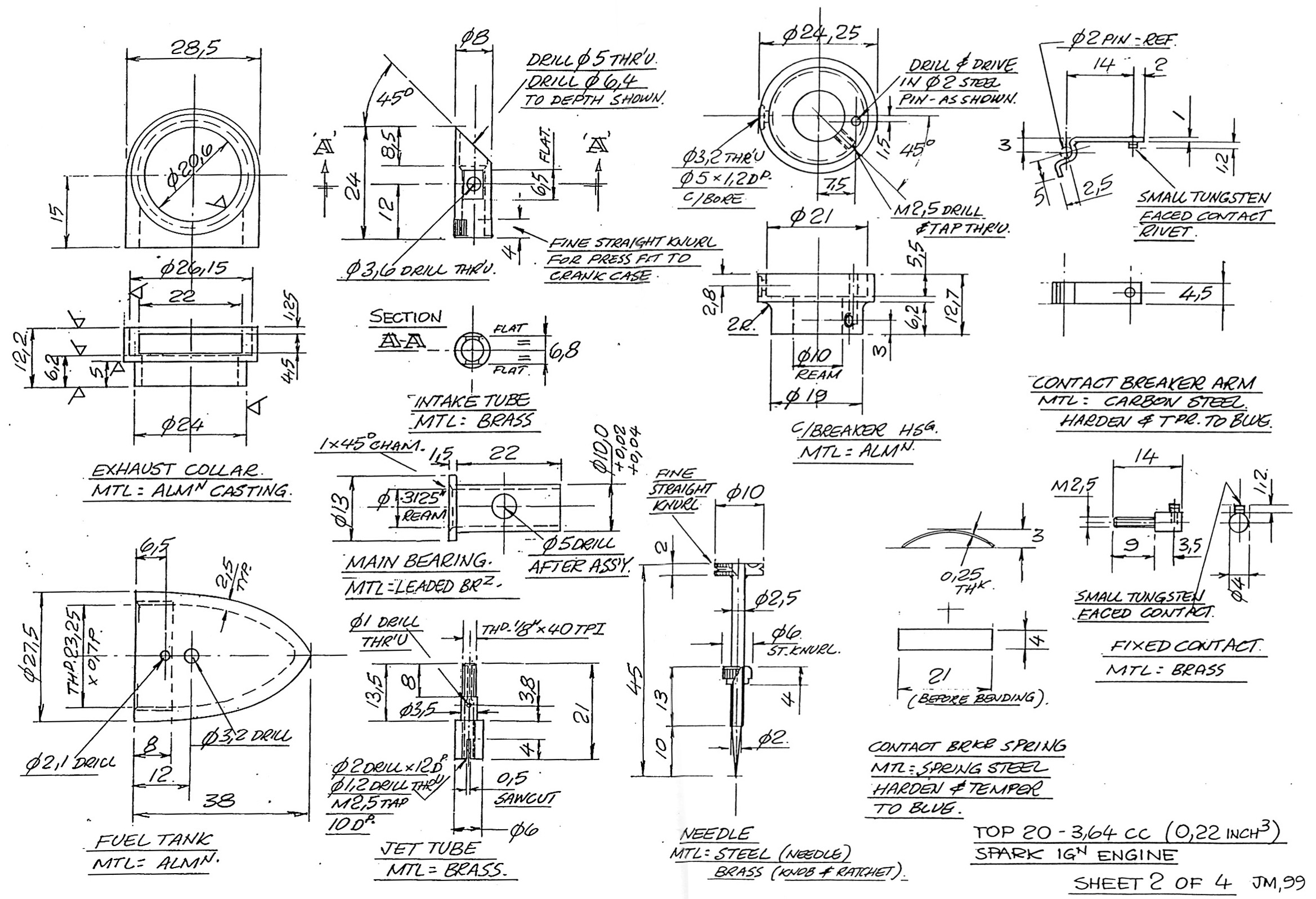
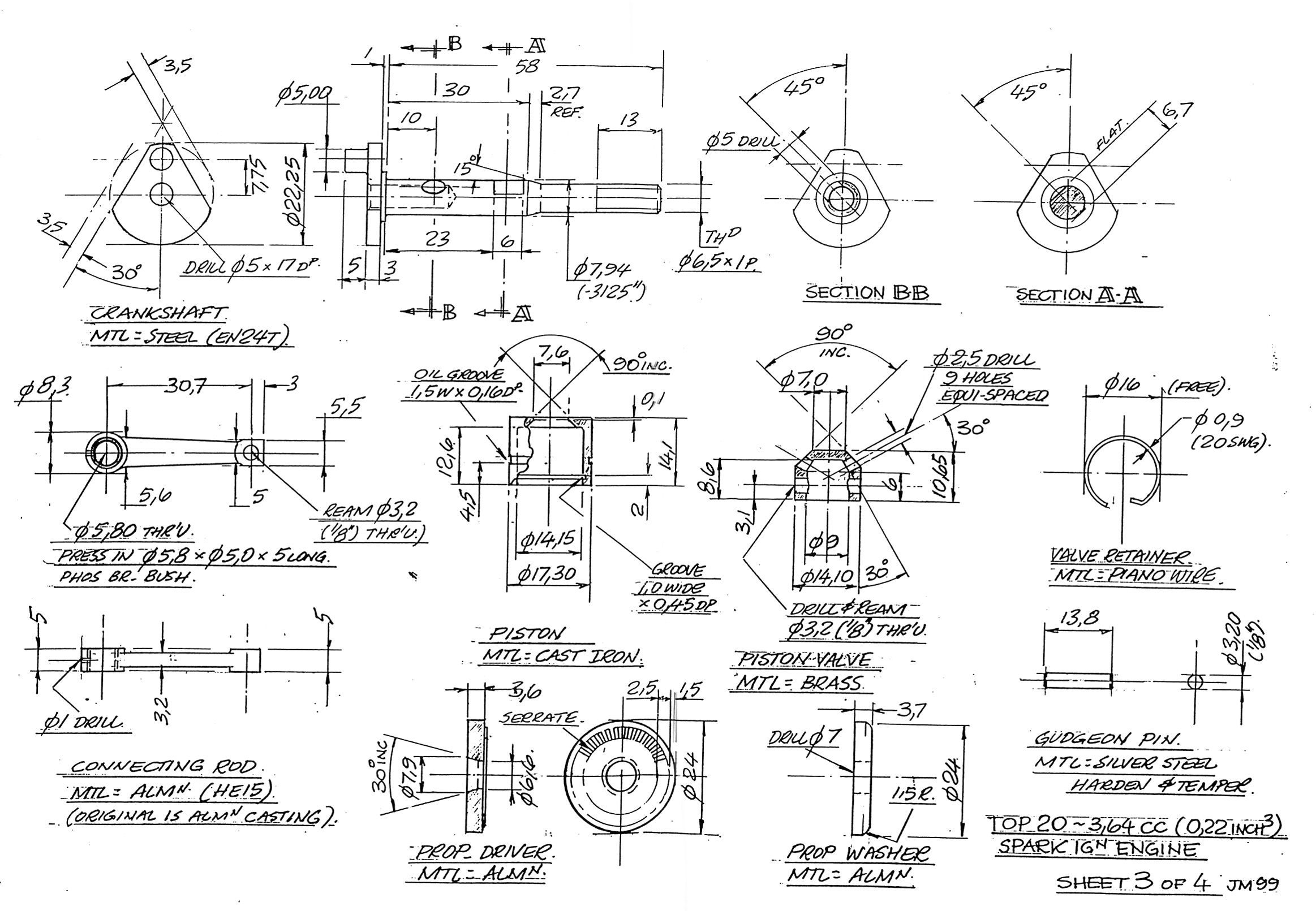
All that is known about this neat and exceptionally well-made little barstock sideport diesel is that it was produced in extremely small numbers by a firm calling themselves Williams & Scott. They worked from an address in Balsall Common, a small rural community lying to the SE of Birmingham about midway between Birmingham and Coventry, England. Production appears to have been confined to the year 1948. The highest serial number confirmed to date is 32, making it appear highly unlikely that production reached anywhere near three figures. Original examples are mega-rare today. Full details of the Wilso 79, inccluding a full test, may be found in the Wilsco 79 article which appears elsewhere on this web-site. Noting the suitability of this barstock engine for home construction, Motor Boy Ken Croft has very kindly prepared a set of TurboCad drawings of the engine and its components. These may be accessed through this link. My very sincere thanks to Ken for his efforts, which I hope will lead to a few more examples being constructed. _________________________________ TOP 20 Sparkie The TOP range from early post-WW2 Japan is the subject of detailed historical article which may be found elsewhere on this website. Amobg the most interesting designs from this manufacturere were their piston-valve models in both .19 (or.20) and .23 cuin. displacements. My valued friend and colleague Ken Croft of Somerset, England drew my attention to the fact that the late John Maddaford, a supremely skilled model engineer, had constructed at least one reproduction example of the TOP 20 piston port model. Not only that, but he had drawn up plans for the engine. These plans are attached below.
If any reader is interested in tackling the construction of one of these engines, it would be very worthwhile to consult the series of articles by Roger Howe on the construction of one of these interesting engines. That series began in the February 2000 issue of the now-defunct "Model Engine World" magazine and continued for a few issues theafter. Scans of these articles can be made available if anyone cares to ask. ____________________________
More plans will be added to this page as and when they are received. ___________________________________ Except where otherwise attributed, all content © Adrian C. Duncan Coquitlam, British Columbia, Canada Page established December 2018 |
 With this thread, I'm creating an area on this website where plans for model engines which can be constructed at home may be found. With the invaluable assistance of my good friend Ken Croft, a resident of Southern France, I've already been privileged to make the
  In late 2019 and early 2020, superb examples of the Clan were completed from these plans both by Ken Croft and Dave Jones of Queensland, Australia. I have engine no. 04 of the series produced by Dave. Although the step-by-step
 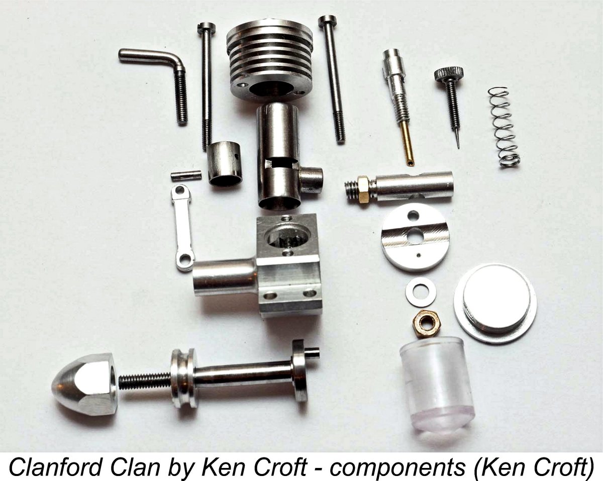 I have some comments that may help anyone planning to build their own example.
 Dave Jones states that he had no issues with the needle as drawn, in either dimension or taper. His engines seem to run well as drawn.
 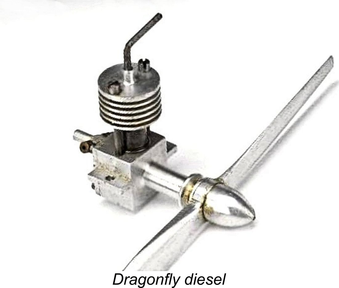 The
The 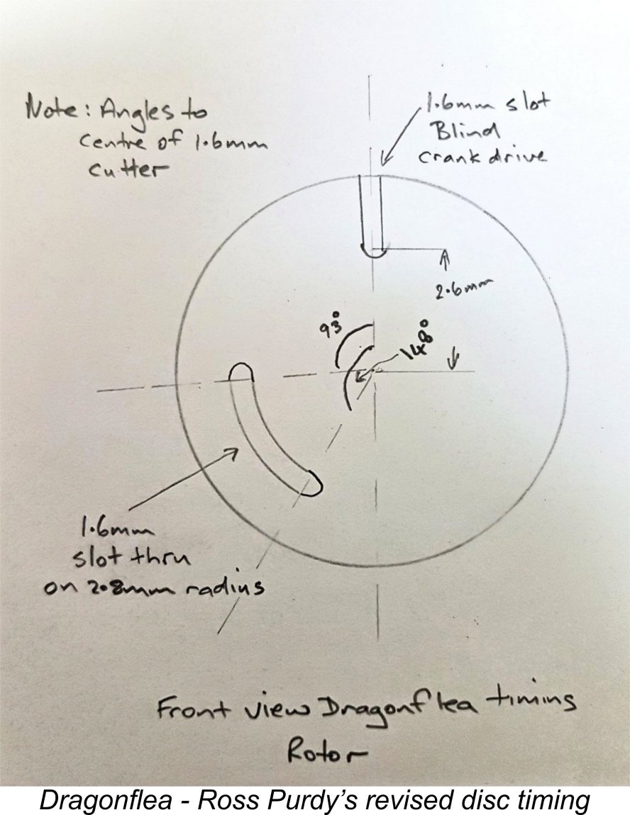

 The Nalon Viper diesel was the final model engine design to come from the drawing board of former
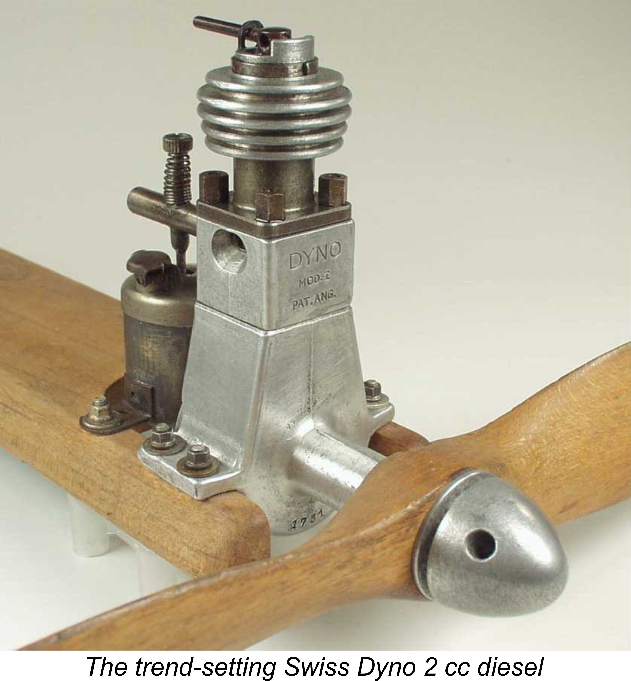
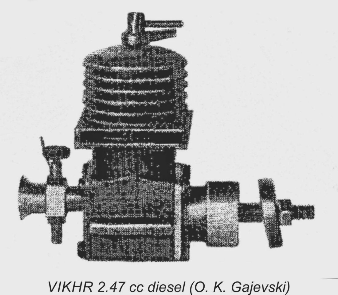 In putting the details of this next engine up in this area of my website, I will admit to taking a bit of a flier! While engaged to the translation of a few Russian-language books from the pioneering and classic eras, I came across some details of a 2.5 cc twin ball race barstock diesel from Kiev in the Ukraine dating from 1954. The engine is called the VIKHR (Vortex). It was designed by E. Sukhov and was entered in a 1954 competition for model engines, finishing second in the 2.5 cc category. Claimed output as demonstrated at the competition was over 0.36 BHP, although I have to say that I’m a bit skeptical! The engine apparently saw limited series production following its competition success.
 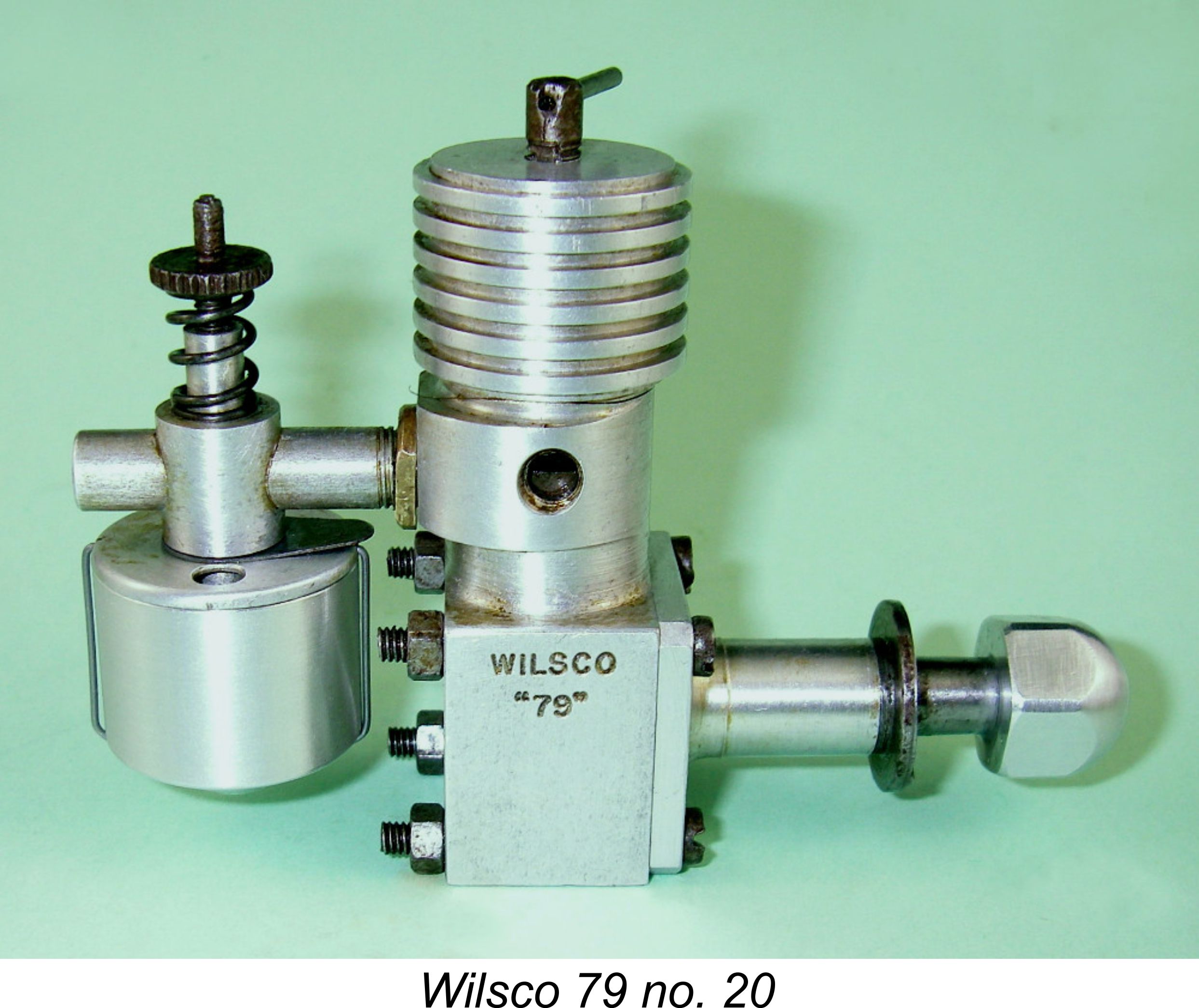 The Wilsco 79 sideport diesel of 0.79 cc displacement is arguably one of the least-known products of the early post-war British model engine manufacturing industry. It even managed to escape the attention of the usually-vigilant Peter Chinn, who encountered an example in 1956 and was reduced to polling his "Model Aircraft" readers to see if anyone could enlighten him regarding the engine's origins. No-one could ...........

.jpg)
| |